

Page 1
Contents
Parameter Guide
Additional Explanation
Panel Descriptions
Patch Mode
Performance Mode
Key Touch
Sample Import
Editing a Patch/Drum Kit
Editing a Performance
Pattern Sequencer
Turning the Display Backlight On/O
Demo Songs
Patch Mode
Patch/Drum Kit Edit
Eects Edit
.......................................... 2
........................................... 2
Realtime Erase
Saving a Pattern As a “Performance” (SAVE AS PERFORM)
......................................... 3
........................................... 4
Procedure
About the Parameters
Patch Parameters
Drum Kit Parameters
......................................... 4
.......................................... 17
Signal Flow
Procedure
Eects Parameters
......................................... 17
Performance Mode
Performance Edit
Procedure
Performance Parameters
Part Edit
Procedure
Performance Parameters
Eects Edit
Signal Flow
Procedure
Eects Parameters
......................................... 19
............................................. 21
......................................... 21
.......................................... 23
......................................... 23
................................ 2
.................................... 2
. . . . . . . . . . . . . . . . . . . . . . . . . . . . . . . . . . . . 2
....................................... 2
................................ 2
.................................. 2
..................................... 3
..................................... 3
...................... 3
.................................... 4
................................ 4
................................... 4
................................. 14
........................................ 17
................................... 18
.................................... 19
..................................... 19
.............................. 19
.............................. 21
........................................ 23
................................... 24
. . . . . . . 3
Creating an Original Scale (USER SCALE)
Setting a User Scale
Recalling a User Scale
System Settings
Procedure
System Parameters
.................................... 31
.................................. 31
....................................... 32
........................................... 32
.................................... 32
Connecting to a Computer via USB
Installing the USB Driver
Making USB Driver Settings
. . . . . . . . . . . . . . . . . . . . . . . . . . . . . . . . 35
............................. 35
Using the JUNO-DS with DAW Software
Using the JUNO-DS As a DAW Controller
Using the JUNO-DS to Control DAW Software
Assigning Functions to Knobs and Sliders
Using the JUNO-DS As a MIDI Keyboard
Playing the JUNO-DS’s Sound Generator from DAW Software
Using the JUNO-DS As an Audio Interface
Saving the DAW CONTROL Settings
Error Messages
........................................ 39
MFX/Chorus/Reverb Parameters
MFX Parameters (MFX, MFX1–3)
Chorus Parameters
Reverb Parameters
Waveform List
Patch List
............................................. 66
Performance List
Drum Kit List
Drum Kit Assign List
.................................... 58
.................................... 58
......................................... 59
...................................... 76
.......................................... 76
................................... 77
....................... 38
....................... 40
.......................... 40
............... 31
..................... 35
................ 36
................... 36
............... 36
.................. 37
.................... 37
.................. 38
... 37
Sample Edit
Procedure
Sample Parameters
Editing Arpeggios
Selecting Ascending/Descending Variations (Motif)
........................................... 25
........................................... 25
.................................... 25
..................................... 29
Editing the Vocoder/Auto Pitch
Saving the Vocoder/Auto Pitch Settings (Write)
© 2015 ROLAND CORPORATION
........... 29
........................ 30
.............. 30
Rhythm Pattern List
Pattern List
............................................ 86
Arpeggio Style List
Vocoder/Auto Pitch List
................................... 85
.................................... 86
................................ 86
Placing This Unit on a Stand
........................... 87
01
Page 2
Additional Explanation
Panel Descriptions
When this button is on (lit), you can use the [0]–[9] buttons to enter
[NUMERIC] button
numeric values.
* You can use this button only in the PATCH screen and PERFORM
screen.
Used to execute an operation.
List display
You can move the cursor to a parameter and press the [ENTER] button
[ENTER] button
to see a list of that parameter’s values.
You can select a value from the list that’s shown.
(Example)
In the PATCH screen, move the cursor to the patch number and press
the [ENTER] button to see the patch list.
Press the [EXIT] button to return to the previous screen.
Patch Mode
5If you press the same category button in succession, the patch changes as follows
each time you press the button.
Each time you press the button, the rst patch of the two subcategories is selected.
If a user patch is saved
Each time you press the button, the rst patch of sub-category
1 0 sub-category 2 0 user 0 sub-category 1 … is selected.
Key Touch
5Depending on the KEY TOUCH setting, the [KEY TOUCH] button is lit or unlit.
Lit When the Velocity setting is “REAL”
Unlit When the Velocity setting is “1–127”
Sample Import
5When importing a sample, the OPTIMIZE window might appear depending on the
user memory usage status.
OK Memory is optimized, and then the sample import is executed.
CANCEL Sample import is cancelled.
Editing a Patch/Drum Kit
PATCH EDIT
5In the PATCH EDIT screen when editing each tone, you can use pads [1]–[8] to
perform the following operations.
Pads [5]–[8]
Pads [1]–[4]
5In the PATCH EDIT screen, press the [MENU] button to open the INIT MENU window.
Select “PATCH” or “TONE” and then press the [ENTER] button to initialize the selected
patch or tone.
Turn each tone on (pad lit) or o.
When a tone is on, a “(” symbol appears.
Make the pad(s) light to specify the tone(s) that you want to edit.
You can also make multiple pads light to select multiple tones.
If a user patch is saved
Each time you press the button, the rst patch of
preset 0 user 0 preset … is selected.
Performance Mode
5You can use pads [1]–[8] to select the applicable part (current part).
5Pressing a pad [1]–[8] selects part 1–8.
5Hold down the [SHIFT] button and press pad [1]–[8] to select part 9–16.
16-part mode
5Within Performance mode, the state in which neither split, dual, nor super layer is
selected is called “16-part mode.”
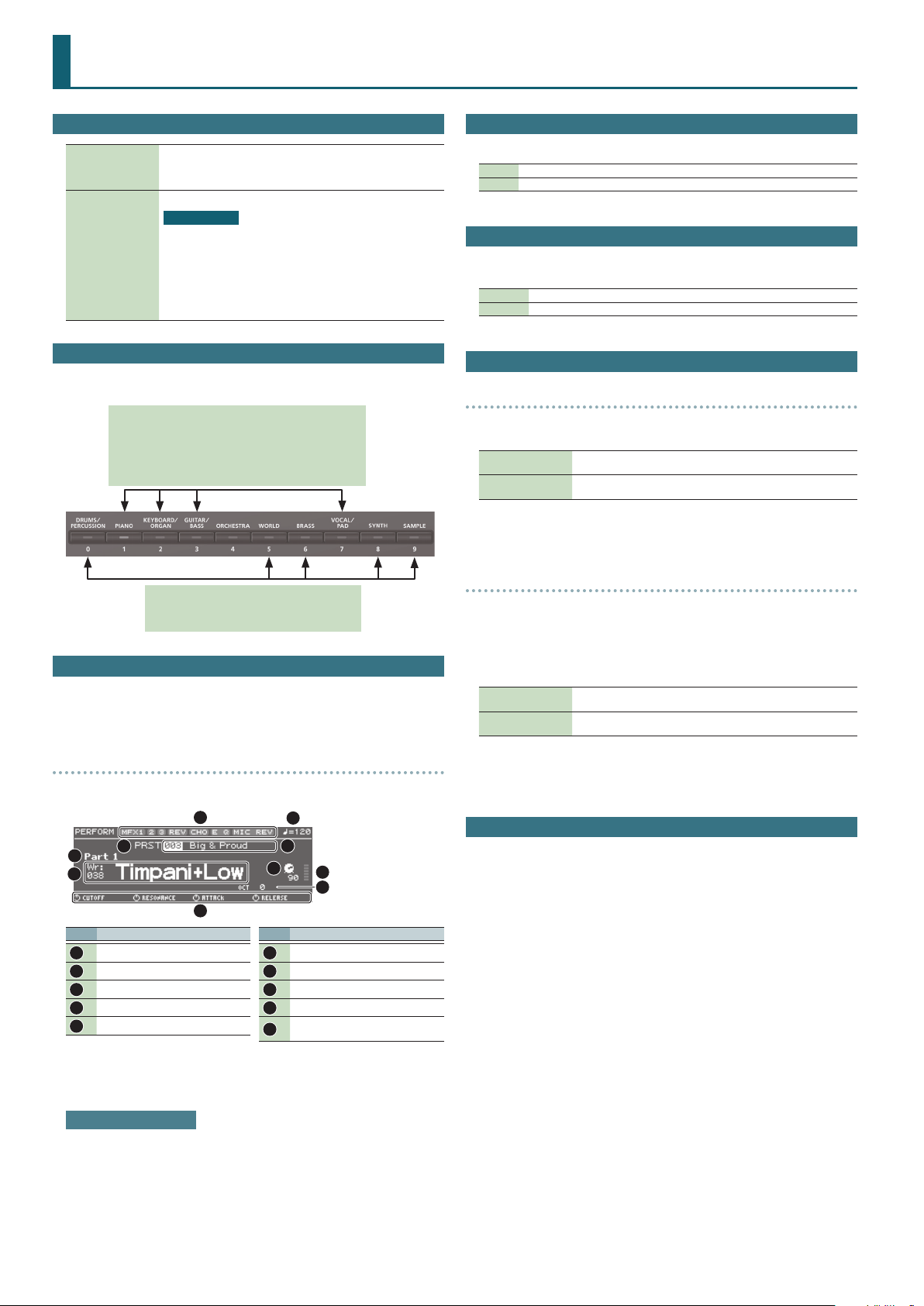
5
6
No. Explanation
1
2
3
4
5
3
Eect on (lit)/o (unlit)
Tempo
Performance bank
Performance number/name
Current part
1
10
2
4
7
8
9
No. Explanation
Category number/Patch name
6
Level of the current part
7
Level meter
8
Octave Shift setting
9
Parameters that can currently be
10
adjusted by the control knobs
DRUM KIT EDIT
5A drum kit consists of a percussion instrument sound (tone) assigned to each key.
The tone that’s assigned to each key consists of a combination of up to four waves.
Drum Kit Edit lets you edit the settings of the tone that’s assigned to each key.
5In the DRUM KIT EDIT screen, when editing the four waves that make up the tone
assigned to the selected key, you can use pads [1]–[8] to perform the following
operations.
Pads [5]–[8]
Pads [1]–[4]
Turn each wave on (pad lit) or o.
When a wave is on, a “(” symbol appears.
Make the pad(s) light to specify the wave(s) that you want to edit.
You can also make multiple pads light to select multiple waves.
5In the DRUM KIT EDIT screen, press the [MENU] button to open the INIT MENU
window. Select “DRUM” or “TONE” and then press the [ENTER] button to initialize the
selected drum kit or the tone of the selected key.
Editing a Performance
5“PERFORMMANCE EDIT” lets you edit while viewing a list of the settings of all parts,
and “PART EDIT” lets you edit each part of the performance individually.
* PERFORMANCE EDIT and PART EDIT have the same parameters in common.
5In the PERFORM EDIT or PART EDIT screen, you can use pads [1]–[8] to select the
part that you want to edit. If you hold down the [SHIFT] button and press a pad [1]–
[8], a part 9–16 is selected.
5In the PERFORM EDIT screen, press the [MENU] button to open the INIT MENU
window. Select “PERFORM” or “PART” and press the [ENTER] button to initialize the
selected performance or part.
When you play the keyboard, you’ll hear the current part and the parts whose
keyboard switch (p. 19, p. 20, p. 22) is on.
Adjusting the volume
You can use the [UPPER] LEVEL slider and [LOWER] LEVEL slider to adjust the part 1
and part 2 volume (LEVEL).
2
Page 3
Pattern Sequencer
5In the PATTERN SEQUENCER screen, you can long-press the [LOOP] button to open
the LOOP window, where you can make loop-related settings. Press the [EXIT]
button to close the LOOP window.
Parameter Explanation
Species whether playback will loop (ON) or not loop (OFF).
Loop Switch
Loop Rec
* You can also switch this by pressing the [LOOP] button.
OFF, ON
Species whether to loop-record (ON) or not loop-record (OFF).
* You can also switch this by pressing the [LOOP] button while holding
down the [SHIFT] button.
OFF, ON
Additional Explanation
Move the cursor to “SAVE AS PERFORM,” and press the [ENTER] button.
4.
The SAVE AS PERFORM screen appears.
Use the value dial to select the write destination performance, and press
5.
the [ENTER] button.
A conrmation message appears.
If you decide to cancel, press the [EXIT] button.
Move the cursor to “OK,” and press the [ENTER] button.
6.
Writing is complete when the screen indicates “Completed!”
NOTE
Never turn o the power while the screen indicates “Writing....”
5Use the [UPPER] slider to adjust the level of track 1, and the [LOWER] slider to adjust
the level of track 2.
5Use the [PHRASE PAD] slider to increase or decrease the level that’s specied for
tracks 3–8 while maintaining the balance between these tracks.
5Press the [MIXER] button to open the MIXER screen. Here you can set the pan and
level of each track.
You can use pads [1]–[8] to select a track to edit.
Use the [UPPER]/[LOWER]/[PHRASE PAD] sliders to adjust the level.
MEMO
Tracks 1–7 are assigned to parts 1–7, and track 8 is assigned to part 10.
Realtime Erase
Erasing only specied notes during recording or playback
(REALTIME NOTE ERASE)
During recording or playback, hold down the [RHYTHM PATTERN] button
1.
and press the [ERASE] button.
The REALTIME NOTE ERASE window appears.
Press a key on the keyboard to specify the note that you want to erase.
2.
Press the [ERASE] button.
3.
While you continue holding down the key, only the note you specify is erased from
the selected track.
Turning the Display Backlight On/O
To reduce battery consumption, you can turn o the display backlight when it’s not
required.
Hold down the [SHIFT] button and press the [EXIT] button.
1.
The display backlight will turn o.
Turning the display backlight on
Hold down the [SHIFT] button and press the [ENTER] button.
1.
The display backlight will turn on.
Demo Songs
1 Wonder
2 There There There
Copyright © 2015 Roland Corporation
Erasing only movements of knobs or the bender/modulation lever
during recording or playback
During recording or playback, hold down the [MUTE] button and press the
1.
[ERASE] button.
Only while you continue holding down these buttons, movements of the knobs and
the bender/modulation lever are erased from the selected track.
Saving a Pattern As a “Performance” (SAVE AS PERFORM)
Settings related to the sound of the pattern (preset/user) used in the pattern
sequencer can be saved as a performance.
For example, if you want to export a pattern to SMF, use your DAW to edit it into a
complete song, and then use the JUNO-DS to play this song data, the performance
saved by the “SAVE AS PERFORM” function can be recalled to play the data using the
original sound.
In the PATTERN SEQUENCER screen, select a pattern.
1.
Press the [MENU] button.
2.
The MENU screen appears.
Move the cursor to “PATTERN UTILITY,” and press the [ENTER] button.
3.
3
Page 4
Patch Mode
Patch/Drum Kit Edit
Procedure
Select a patch or drum kit that you want to edit.
1.
Press the [SAMPLE IMPORT] button and [DAW CONTROL] button
2.
simultaneously.
The EDIT MENU screen appears.
Move the cursor to “PATCH EDIT” or “DRUM KIT EDIT,” and press the [ENTER]
3.
button.
The PATCH EDIT or DRUM KIT EDIT screen appears.
MEMO
5In the PATCH EDIT screen when editing each tone, you can use pads [1]–[8] to
perform the following operations.
Pads [5]–[8]
Pads [1]–[4]
5In the PATCH EDIT screen, press the [MENU] button to open the INIT MENU
window. Select “PATCH” or “TONE” and then press the [ENTER] button to
initialize the selected patch or tone.
Turn each tone on (pad lit) or o.
When a tone is on, a “(” symbol appears.
Make the pad(s) light to specify the tone(s) that you want to edit.
You can also make multiple pads light to select multiple tones.
MEMO
5In the DRUM KIT EDIT screen, when editing the four waves that make up the
tone assigned to the selected key, you can use pads [1]–[8] to perform the
following operations.
Pads [5]–[8]
Pads [1]–[4]
5In the DRUM KIT EDIT screen, press the [MENU] button to open the INIT MENU
window. Select “DRUM” or “TONE” and then press the [ENTER] button to
initialize the selected drum kit or the tone of the selected key.
Move the cursor to tab, and use the [K] [J] buttons to switch the pages.
4.
Move the cursor to the parameter that you want to edit, and use the value
5.
dial to change the value.
To save the edited settings, perform the operation “Saving Your Settings
6.
(Write)” (refer to owner’s manual).
Turn each wave on (pad lit) or o.
When a wave is on, a “(” symbol appears.
Make the pad(s) light to specify the wave(s) that you want to edit.
You can also make multiple pads light to select multiple waves.
About the Parameters
5Parameters marked with a “2” can be controlled using Matrix control (p. 12).
5Some parameters (such as Rate or Delay Time) can be set in terms of a note value.
Sixty-fourthnote triplet
Sixteenth-note
triplet
Dotted
sixteenth note
Quarter note Half-note triplet
Whole-note
triplet
Dotted whole
note
Sixty-fourth
note
Dotted thirtysecond note
Eighth note
Dotted half note Whole note
Double note
Thirty-secondnote triplet
Sixteenth note
Quarter-note
triplet
Dotted quarter
note
Thirty-second
note
Eighth-note
triplet
Dotted eighth
note
Half note
Double-note
triplet
NOTE
If you specify the delay time as a note value, slowing down the tempo will not
change the delay time beyond a certain length.
This is because there is an upper limit for the delay time; if the delay time is
specied as a note value and you slow down the tempo until this upper limit
is reached, the delay time cannot change any further. This upper limit is the
maximum value that can be specied when setting the delay time as a numerical
value.
Patch Parameters
COMMON
Parameter Value/Explanation
Species the type (category) of the patch.
Patch Category
Patch Level
Patch Pan
Patch Priority
Octave Shift
Patch Coarse Tune
Patch Fine Tune
Stretch Tune
Depth
Analog Feel
Cuto Oset
Resonance Oset
Attack Time Oset
Release Time
Oset
* If you select “NO ASSIGN” as the category, it won’t be possible to select
the patch on the JUNO-DS itself.
Refer to “Category List” (p. 5).
Species the volume of the patch.
0–127
Species the pan of the patch.
“L64” is far left, “0” is center, and “63R” is far right.
L64–0–63R
This determines how notes will be managed when the maximum
polyphony is exceeded (128 voices).
LAST
LOUDEST
Adjusts the pitch of the patch’s sound up or down in units of an octave (±3
octaves).
-3–3
Adjusts the pitch of the patch’s sound up or down in semitone steps (±4
octaves).
-48–48
Adjusts the pitch of the patch’s sound up or down in 1-cent steps (±50
cents).
-50–50
Stretched tuning (a system by which acoustic pianos are normally tuned,
causing the lower range to be lower and the higher range to be higher
than the mathematical tuning ratios would otherwise dictate)
OFF Equal temperament
1–3
Species the depth of 1/f modulation that is to be applied to the patch.
By adding this “1/f modulation,” you can simulate the natural instability
characteristic of an analog synthesizer.
0–127
Cuto Frequency Oset alters the cuto frequency of the overall patch,
while preserving the relative dierences between the cuto frequency
values set for each tone in the Cuto Frequency (p. 8).
* This value is added to the cuto frequency value of a tone, so if the
cuto frequency value of any tone is already set to “127” (maximum),
positive “+” settings here will not produce any change.
-63–+63
Resonance Oset alters the resonance of the overall patch, while
preserving the relative dierences between the resonance values set for
each tone in the Resonance (p. 8).
* This value is added to the resonance value of a tone, so if the resonance
value of any tone is already set to “127” (maximum), positive “+” settings
here will not produce any change.
-63–+63
Attack Time Oset alters the attack time of the overall patch, while
preserving the relative dierences between the attack time values set for
each tone in the TVA-Env Time 1 (p. 10), TVF-Env Time 1 (p. 9).
* This value is added to the attack time value of a tone, so if the attack
time value of any tone is already set to “127” (maximum), positive “+”
settings here will not produce any change.
-63–+63
Release Time Oset alters the release time of the overall patch, while
preserving the relative dierences between the release time values set for
each tone in the TVA-Env Time 4 (p. 10), TVF-Env Time 4 (p. 9).
* This value is added to the release time value of a tone, so if the release
time value of any tone is already set to “127” (maximum), positive “+”
settings here will not produce any change.
-63–+63
The last-played voices will be given priority, and currently
sounding notes will be turned o in order, beginning with
the rst-played note.
The voices with the loudest volume will be given priority,
and currently sounding notes will be turned o, beginning
with the lowest-volume voice.
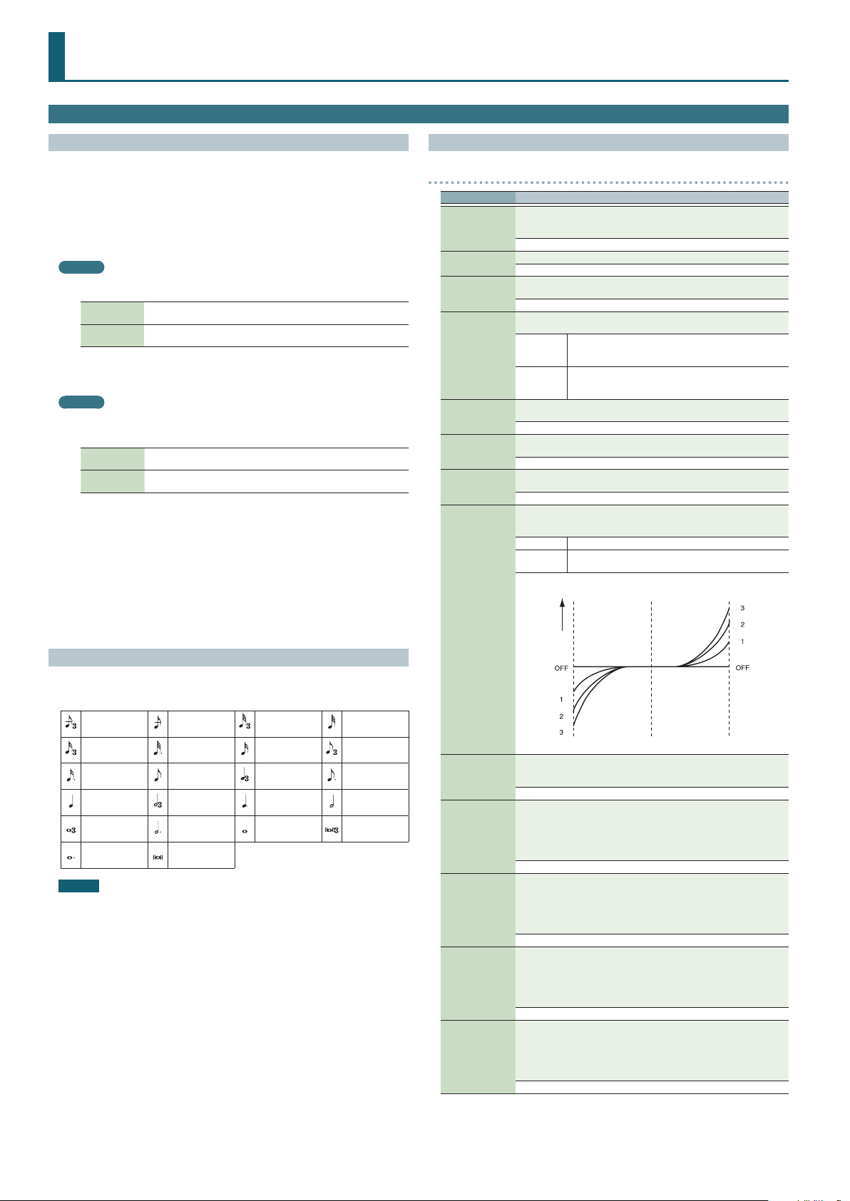
Higher settings will produce the greater dierence in the
pitch of the low and high ranges.
Pitch dierence from
equal temperament
Low note range High note range
Parameter value
4
Page 5
Patch Mode
Parameter Value/Explanation
Velocity Sens Oset alters the Velocity Sensitivity of the overall patch while
preserving the relative dierences between the Velocity Sensitivity values
set for each tone in the parameters below.
Velocity Sens
Oset
Mono/Poly
Legato Switch
Legato Retrigger
MEMO
Let’s say you have the Legato Switch set to “ON,” and the Legato Retrigger set to “OFF.” When
you try to sound a legato (by pressing a higher key while a lower key is held down), the pitch
may sometimes not be able to rise all the way to the intended pitch (stopping instead at an
intermediate pitch). This can occur because the limit of pitch rise, as determined at the wave
level, has been exceeded. Additionally, if diering upper pitch limits are used for the waves of
a Patch that uses multiple tones, it may stop being heard in MONO. When making large pitch
changes, set the Legato Retrigger to “ON.”
Portamento
Switch
Portamento Mode
Portamento Type
Cuto V-Sens (p. 9)
Level V-Sens (p. 10)
* This value is added to the velocity sensitivity value of a tone, so if the
velocity sensitivity value of any tone is already set to “+63” (maximum),
positive “+” settings here will not produce any change.
-63–+63
Species whether the patch will play polyphonically (POLY) or
monophonically (MONO).
The “MONO” setting is eective when playing a solo instrument patch such
as sax or ute.
MONO Only the last-played note will sound.
POLY Two or more notes can be played simultaneously.
Species whether the Legato Switch will be used (ON) or not (OFF).
With the Legato Switch parameter “ON,” pressing a key while continuing
to press a previous key causes the note to change pitch to the pitch of the
most recently pressed key, sounding all the while. This creates a smooth
transition between notes, which is eective when you wish to simulate the
hammering-on and pulling-o techniques used by a guitarist.
* Legato Switch is valid when the Mono/Poly is set to “MONO.”
OFF, ON
The setting determines whether sounds are replayed (ON) or not (OFF)
when performing legato. Normally you will leave this parameter “ON.”
When “OFF,” when one key is held down and another key is then pressed,
only the pitch changes, without the attack of the latter key being played.
Set this to “OFF” when performing wind and string phrases or when using
modulation with the mono synth keyboard sound.
* Legato Retrigger is valid when the Mono/Poly is set to “MONO” and the
Legato Switch is set to “ON.”
OFF, ON
Species whether the portamento eect will be applied (ON) or not (OFF).
OFF, ON
Species the performance conditions for which portamento will be
applied.
NORMAL Portamento will always be applied.
LEGATO
Species the type of portamento eect.
RAT E
TIME
When another key is pressed during a pitch change produced by
portamento, a new pitch change will begin. This setting species the pitch
at which the change will begin.
PITCH
Portamento will be applied only when you play legato (i.e.,
when you press the next key before releasing the previous
key).
The time it takes will depend on the distance between the
two pitches.
The time it takes will be constant, regardless of how far
apart in pitch the notes are.
Starts a new portamento when another key is pressed while
the pitch is changing.
Pitch
Parameter Value/Explanation
When portamento is used, this species the time over which the pitch will
Portamento Time
change. Higher settings will cause the pitch change to the next note to
take more time.
0–127
Category List
Category Contents
- - - No assign No assign
PNO AC. Piano Acoustic Piano
EP EL. Piano Electric Piano
KEY Keyboards Other Keyboards (Clav, Harpsichord etc.)
BEL Bell Bell, Bell Pad
MLT Mallet Mallet
ORG Organ lectric and Church Organ
ACD Accordion Accordion
HRM Harmonica Harmonica, Blues Harp
AGT AC.Guitar Acoustic Guitar
EGT EL.Guitar Electric Guitar
DGT DIST. Guitar Distortion Guitar
BS Bass Acoustic & Electric Bass
SBS Synth Bass Synth Bass
STR Strings Strings
ORC Orchestra Orchestra Ensemble
HIT Hit&Stab Orchestra Hit, Hit
WND Wind Winds (Oboe, Clarinet etc.)
FLT Flute Flute, Piccolo
BRS AC. Brass Acoustic Brass
SBR Synth Brass Synth Brass
SAX Sax S ax
HLD Hard Lead Hard Synth Lead
SLD Soft Lead Soft Synth Lead
TEK Techno Synth Techno Synth
PLS Pulsating Pulsating Synth
FX Synth FX Synth FX (Noise etc.)
SYN Other Synth Poly Synth
BPD Bright Pad Bright Pad Synth
SPD Soft Pad Soft Pad Synth
VOX Vox Vox, Choir
PLK Plucked Plucked (Harp etc.)
ETH Ethnic Other Ethnic
FRT Fretted Fretted Inst (Mandolin etc.)
PRC Percussion Percussion
SFX Sound FX Sound FX
BTS Beat&Groove Beat and Groove
DRM Drums Drum Set
CMB Combination Other patches which use Split and Layer
Portamento Start
NOTE
press D4 key
press C4 key
Portamento will begin anew from the pitch where the
current change would end.
Pitch
press C4 key
press C5 key
press C5 key
press D4 key
Time
Time
5
Page 6

Patch Mode
WAVE
Parameter Value/Explanation
1– *4
*
Wave Group
Wave No. L (Mono)
Wave No. R
Wave Gain
Wave Tempo Sync
Wave FXM Switch
Wave FXM Color
Wave FXM Depth
2
Specify the on/o status of tones 1–4. If a tone is on, a “(” mark is shown.
OFF, ON
Selects the group for the waveform that is to be the basis of the tone.
INTA, B Waveforms stored in internal
EXP Waveforms for expansion sounds
Selects the basic waveform for a tone. Along with the Wave number, the
Wave name appears at the lower part of the display.
When in mono, only the left side (L) is specied. When in stereo, the right
side (R) is also specied.
OFF, 1–2402 (The upper limit will depend on the wave group.)
Sets the gain (amplication) of the waveform. The value changes in 6 dB
(decibel) steps—an increase of 6 dB doubles the waveform’s gain.
If you intend to use the Booster to distort the waveform’s sound, set this
parameter to its maximum value (p. 7).
-6, 0, +6, +12
When you wish to synchronize a Phrase Loop to the clock (tempo), set this
to “ON.”
OFF, ON
MEMO
Phrase loop refers to the repeated playback of a phrase that’s been pulled
out of a song (e.g., by using a sampler).
Sets whether FXM will be used (ON) or not (OFF).
OFF, ON
MEMO
FXM (Frequency Cross Modulation) uses a specied waveform to apply
frequency modulation to the currently selected waveform, creating
complex overtones. This is useful for creating dramatic sounds or sound
eects.
Species how FXM will perform frequency modulation. Higher settings
result in a grainier sound, while lower settings result in a more metallic
sound.
1–4
Species the depth of the modulation produced by FXM.
0–16
Selects the type of tone delay.
NORM
The tone begins to play after the time specied in the Tone
Delay Time has elapsed.
No Tone Delay
Parameter Value/Explanation
OFF-D
MEMO
If you have selected a waveform that is a decay-type sound (i.e., a sound that fades away
naturally even if the key is not released), selecting “OFF-N” or “OFF-D” may result in no sound
being heard.
Species the time from when the key is pressed (or if the Delay Mode is set
Tone Delay Time
to “OFF-N” or “OFF-D,” the time from when the key is released) until when
the tone will sound.
0–127, note
Rather than being played while the key is pressed, the tone
begins to play once the period of time specied in the
Tone Delay Time has elapsed after release of the key. Here,
however, changes in the TVA Envelope begin while the key
is pressed, which in many cases means that only the sound
from the release portion of the envelope is heard.
Delay time
Note on Note o
TMT
Parameter Value/Explanation
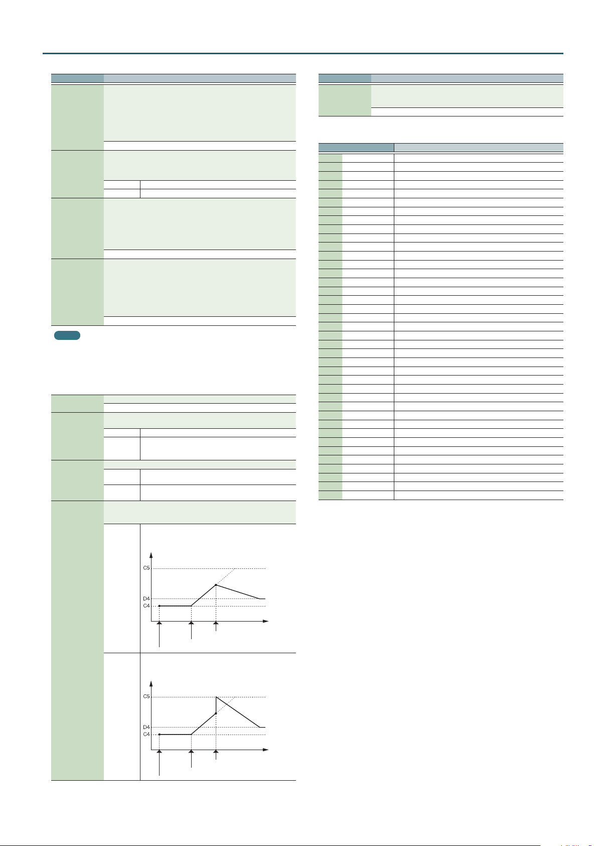
Determines how tone 1 and 2, or tone 3 and 4 are connected.
The following 10 dierent Types of combination are available.
1
2
With this type, tones 1 and 2 (or 3 and 4) are independent.
Use this type when you want to preserve PCM sounds or
create and combine sounds for each tone.
This type stacks the two lters together to intensify the
characteristics of the lters. The TVA for tone 1 (or 3) controls
the volume balance between the two tones.
Tone Delay Mode
Delay time
Note on
HOLD Although the tone begins to play after the time specied
OFF-N
in the Tone Delay Time has elapsed, if the key is released
before the time specied in the Tone Delay Time has
elapsed, the tone is not played.
Note on Note o
Rather than being played while the key is pressed, the tone
begins to play once the period of time specied in the
Tone Delay Time has elapsed after release of the key. This is
eective in situations such as when simulating noises from
guitars and other instruments.
Note o
No sound played
Delay time
Structure Type
1 & 2, 3 & 4
3 This type mixes the sound of tone 1 (3) and tone 2 (4),
4
5
6
applies a lter, and then applies a booster to distort the
waveform.
This type applies a booster to distort the waveform, and
then combines the two lters. The TVA for tone 1 (or 3)
controls the volume balance between the two tones and
adjusts booster level.
This type uses a ring modulator to create new overtones,
and combines the two lters. The tone 1 (3) TVA will control
the volume balance of the two tones, adjusting the depth of
ring modulator.
This type uses a ring modulator to create new overtones,
and in addition mixes in the sound of tone 2 (4) and stacks
the two lters. Since the ring-modulated sound can be
mixed with tone 2 (4), tone 1 (3) TVA can adjust the amount
of the ring-modulated sound.
Note on Note o
6
Page 7
Patch Mode
Parameter Value/Explanation
7
8
9
10 This type passes the ltered sound of each tone through a
MEMO
5When type 2–10 is selected and one tone of a pair is turned o, the other tone will be
sounded as type 1 regardless of the displayed setting.
5If you limit the keyboard area in which a tone will sound (Key Range Upper, Lower) or limit
the range of velocities for which it will sound (Velo Range Upper, Lower), the result in areas
or ranges where the tone does not sound is just as if the tone had been turned o. This
means that if type 2–10 is selected and you create a keyboard area or velocity range in which
one tone of a pair does not sound, notes played in that area or range will be sounded by the
other tone as TYPE 1 regardless of the displayed setting.
When a Structure Type of 3 or 4 is selected, you can adjust the depth of
Booster
1 & 2, 3 & 4
Key Fade Upper,
Lower
Key Range
Upper, Lower
TMT Velocity
Control
Velo Fade Upper,
Lower
the booster. The booster increases the input signal in order to distort
the sound. This creates the distortion eect frequently used with electric
guitars. Higher settings will produce more distortion.
0, +6, +12, +18
This determines what will happen to the tone’s level when a note that’s
higher/lower than the tone’s specied keyboard range is played.
Higher settings produce a more gradual change in volume. If you don’t
want the tone to sound at all when a note below the keyboard range is
played, set this parameter to “0.”
0–127
Species the highest/lowest note that the tone will sound for each tone.
* If you attempt to raise the lower key higher than the upper key, or
(Upper) LOWER–G9, (Lower) C-1–UPPER
Level
Fade Lower
Range Lower Range Upper
TMT Velocity Control determines whether a dierent tone is played or not
depending on the force with which the key is played (velocity).
* Instead of using Velocity, you can also have tones substituted using the
OFF Tones are not velocity-switched.
ON
RANDOM
CYCLE
This determines what will happen to the tone’s level when the tone is
played at a velocity Upper/lower than its specied velocity range. Higher
settings produce a more gradual change in volume. If you want notes
played outside the specied key velocity range to not be sounded at all,
set this to “0.”
0–127
This type applies a lter to tone 1 (3) and ring-modulates it
with tone 2 (4) to create new overtones.
This type sends the ltered tone 1 (3) and tone 2 (4) through
a ring modulator, and then mixes in the sound of tone 2 (4)
and applies a lter to the result.
This type passes the ltered sound of each tone through a
ring modulator to create new overtones. The tone 1 (3) TVA
will control the volume balance of the two tones, adjusting
the depth of ring modulator.
ring modulator to create new overtones, and also mixes in
the sound of tone 2 (4). Since the ring-modulated sound
can be mixed with tone 2 (4), tone 1 (3) TVA can adjust the
amount of the ring-modulated sound.
to lower the upper key below the lower key, the other value will be
automatically modied to the same setting.
Pitch
Fade Upper
Matrix control (p. 12). However, the keyboard velocity and the Matrix
control cannot be used simultaneously to make dierent tones to
sound. When using the Matrix control to switch tones, set the Velocity
Control to “OFF.”
Tones are switched according to the keyboard playing
velocity.
The patch’s constituent tones will sound randomly,
regardless of the velocity.
The patch’s constituent tones will sound consecutively,
regardless of the velocity.
Parameter Value/Explanation
Sets the highest/lowest velocity at which the tone will sound.
Velo Range
Upper, Lower
MEMO
When using the Matrix Control to have dierent tones played, set the lowest value (Lower) and
highest value (Upper) of the value of the MIDI message used.
TMT Control
Switch
* If you attempt to set the Lower velocity limit above the Upper, or the
Upper below the Lower, the other value will automatically be adjusted
to the same setting.
(Upper) LOWER–127, (Lower) 1–UPPER
Level
Fade Lower
Range Lower Range Upper
Use the Matrix control to enable (ON), or disable (OFF) sounding of
dierent tones.
* You can also cause dierent tones to sound in response to notes
played at dierent strengths (velocity) on the keyboard (p. 7).
However, the Matrix control and the keyboard velocity cannot be used
simultaneously to make dierent tones to sound. When you want to
make the dierent tones to sound, set the TMT Velocity Control (p. 7)
to “OFF.”
OFF, ON
Fade Upper
Velocity
PITCH
Parameter Value/Explanation
Adjusts the pitch of the tone’s sound up or down in semitone steps (±4
Tone Coarse Tune
Tone Fine Tune
Random Pitch
Depth
Pitch Keyfollow
Pitch Bend Range
Up, Down
octaves).
-48–+48
Adjusts the pitch of the tone’s sound up or down in 1-cent steps (±50
cents).
-50–+50
Species the width of random pitch deviation that will occur each time a
key is pressed. If you do not want the pitch to change randomly, set this to
“0.” These values are in units of cents (1/100th of a semitone).
0–1200
Species the amount of pitch change that will occur when you play a key
one octave higher (i.e., 12 keys upward on the keyboard).
If you want the pitch to rise one octave as on a conventional keyboard, set
this to “+100.” If you want the pitch to rise two octaves, set this to “+200.”
Conversely, set this to a negative value if you want the pitch to fall. With a
setting of “0,” all keys will produce the same pitch.
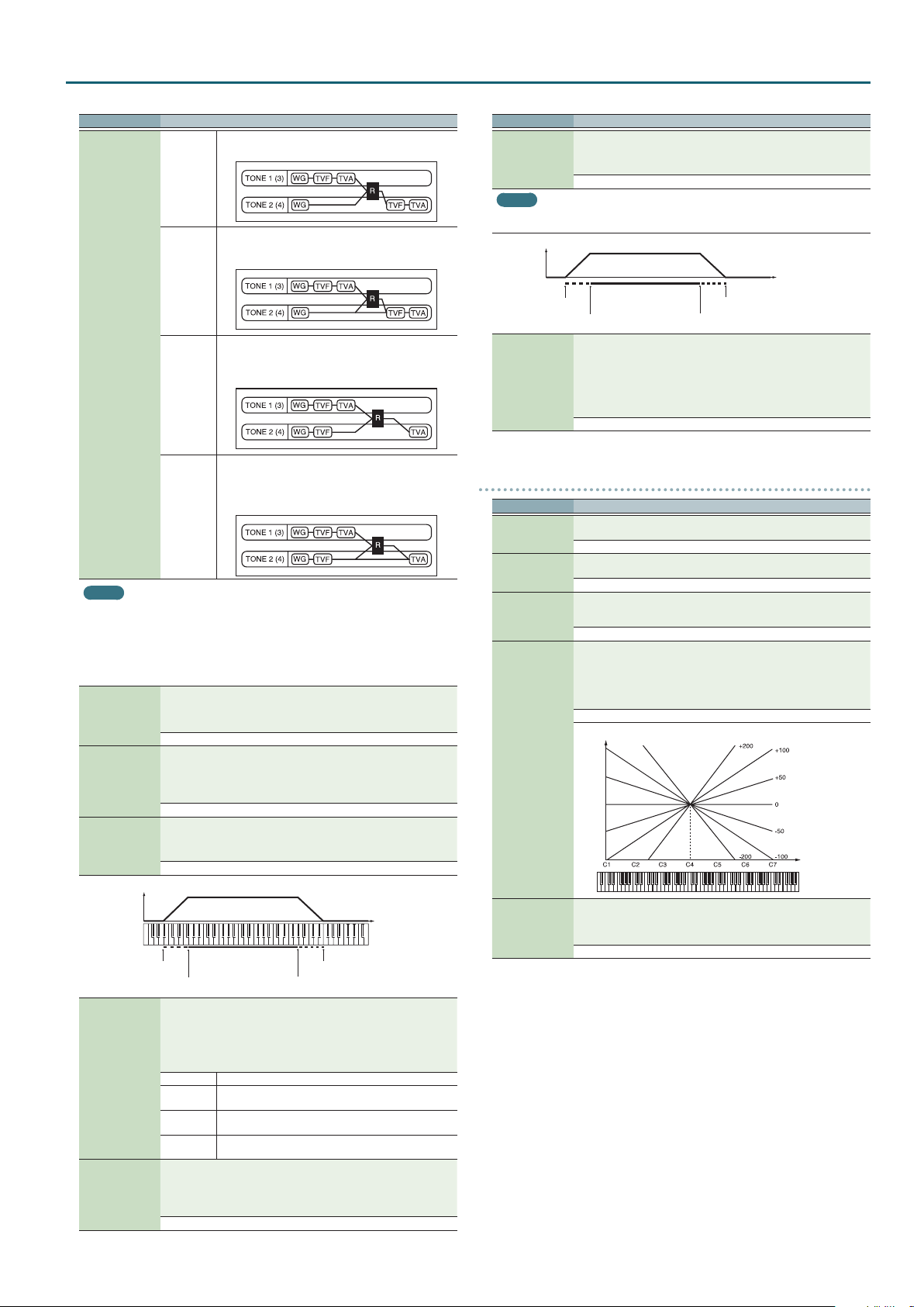
-200–+200
Pitch
Key
Species the degree of pitch change in semitones when the Pitch Bend
lever is all the way right (left).
For example if this is set to “+48 (-48)” and you move the pitch bend lever
all the way to the right (left), the pitch will rise (fall) 4 octaves.
(Up) 0–+48, (Down) 0– -48
7
Page 8
Patch Mode
PITCH ENV
Parameter Value/Explanation
Adjusts the eect of the Pitch Envelope. Higher settings will cause the
Pitch Env Depth
Pitch Env V-Sens
Pitch Env T1
V-Sens
Pitch Env T4
V-Sens
Pitch Env Time KF
pitch envelope to produce greater change. Negative (-) settings will invert
the shape of the envelope.
-12–+12
Keyboard playing dynamics can be used to control the depth of the pitch
envelope. If you want the pitch envelope to have more eect for strongly
played notes, set this parameter to a positive (+) value. If you want the
pitch envelope to have less eect for strongly played notes, set this to a
negative (-) value.
-63–+63
This allows keyboard dynamics to aect the Time 1 of the Pitch envelope.
If you want Time 1 to be speeded up for strongly played notes, set this
parameter to a positive (+) value. If you want it to be slowed down, set this
to a negative (-) value.
-63–+63
Use this parameter when you want key release speed to aect the Time
4 value of the pitch envelope. If you want Time 4 to be speeded up for
quickly released notes, set this parameter to a positive (+) value. If you
want it to be slowed down, set this to a negative (-) value.
-63–+63
Use this setting if you want the pitch envelope times (Time 2–Time 4) to
be aected by the keyboard location. Based on the pitch envelope times
for the C4 key, positive (+) settings will cause notes higher than C4 to
have increasingly shorter times, and negative (-) settings will cause them
to have increasingly longer times. Larger settings will produce greater
change.
-100–+100
Time
TVF
Parameter Value/Explanation
Selects the type of lter. A lter cuts or boosts a specic frequency region
to change a sound’s brightness, thickness, or other qualities.
* If you set “LPF2” or “LPF3,” the setting for the Resonance (p. 8) will be
ignored .
OFF No lter is used.
LPF
BPF
HPF
PKG
LPF2
Filter Type
LPF3
Low Pass Filter. This reduces the volume of all frequencies above
the cuto frequency in order to round o, or un-brighten the
sound. This is the most common lter used in synthesizers.
Band Pass Filter. This leaves only the frequencies in the region of
the cuto frequency, and cuts the rest. This can be useful when
creating distinctive sounds.
High Pass Filter. This cuts the frequencies in the region below the
cuto frequency. This is suitable for creating percussive sounds
emphasizing their higher tones.
Peaking Filter. This emphasizes the frequencies in the region of
the cuto frequency. You can use this to create wah-wah eects
by employing an LFO to change the cuto frequency cyclically.
Low Pass Filter 2. Although frequency components above the
cuto frequency are cut, the sensitivity of this lter is half that of
the LPF. This makes it a comparatively warmer low pass lter. This
lter is good for use with simulated instrument sounds such as
the acoustic piano.
Low Pass Filter 3. Although frequency components above the
cuto frequency are cut, the sensitivity of this lter changes
according to the cuto frequency. While this lter is also good
for use with simulated acoustic instrument sounds, the nuance
it exhibits diers from that of the LPF2, even with the same TVF
Envelope settings.
Pitch Env Time 1–4
2
Pitch Env Level
0–4
Key
Specify the pitch envelope times (Time 1–Time 4).
Higher settings will result in a longer time until the next pitch is reached.
(For example, Time 2 is the time over which the pitch changes from Level 1
to Level 2.)
0–127
Specify the pitch envelope levels (Level 0–Level 4).
It determines how much the pitch changes from the reference pitch (the
value set with Coarse Tune or Fine Tune on the Pitch screen) at each point.
Positive (+) settings will cause the pitch to be higher than the standard
pitch, and negative (-) settings will cause it to be lower.
-63–+63
Pitch
Note on
T: Time L: Level
Note o
Time
Cuto Frequency
2
Resonance
2
Cuto Keyfollow
Selects the frequency at which the lter begins to have an eect on the
waveform’s frequency components.
“LPF/LPF2/LPF3” selected for the Filter Type
Lower cuto frequency settings reduce a tone’s upper harmonics for a
more rounded, warmer sound. Higher settings make it sound brighter.
“BPF” selected for the Filter Type
Harmonic components will change depending on the TVF Cuto
Frequency setting. This can be useful when creating distinctive sounds.
“HPF” selected for the Filter Type
Higher Cuto Frequency settings will reduce lower harmonics to
emphasize just the brighter components of the sound.
“PKG” selected for the Filter Type
The harmonics to be emphasized will vary depending on Cuto Frequency
setting.
MEMO
To edit the overall patch while preserving the relative dierences in the
Cuto Frequency values set for each tone, set the Cuto Oset (p. 4).
0–127
Emphasizes the portion of the sound in the region of the cuto frequency,
adding character to the sound. Excessively high settings can produce
oscillation, causing the sound to distort.
0–127
Use this parameter if you want the cuto frequency to change according
to the key that is pressed. Relative to the cuto frequency at the C4 key
(center C), positive (+) settings will cause the cuto frequency to rise
for notes higher than C4, and negative (-) settings will cause the cuto
frequency to fall for notes higher than C4.
Larger settings will produce greater change.
-200–+200
Cuto frequency
(Octave)
Key
8
Page 9
Patch Mode
Parameter Value/Explanation
Selects one of the following seven curves that determine how keyboard
playing dynamics (velocity) inuence the cuto frequency.
Set this to “FIXED” if you don’t want the Cuto frequency to be aected by
the keyboard velocity.
Cuto V-Curve
Cuto V-Sens
Resonance V-Sens
FIXED, 1–7
Use this parameter when changing the cuto frequency to be applied as a
result of changes in playing velocity. If you want strongly played notes to
raise the cuto frequency, set this parameter to positive (+) settings. If you
want strongly played notes to lower the cuto frequency, use negative (-)
settings.
MEMO
To edit the overall patch while preserving the relative dierences in the
Cuto V-Sens values set for each tone, set the Velocity Sens Oset (p. 5).
However, this setting is shared by the Level V-Sens (p. 10).
-63–+63
This allows keyboard velocity to modify the amount of Resonance. If you
want strongly played notes to have a greater Resonance eect, set this
parameter to positive (+) settings. If you want strongly played notes to
have less Resonance, use negative (-) settings.
-63–+63
TVF ENV
Parameter Value/Explanation
Species the depth of the TVF envelope. Higher settings will cause the TVF
TVF Env Depth
TVF Env V-Curve
TVF Env V-Sens
TVF Env T1 V-Sens
TVF Env T4 V-Sens
envelope to produce greater change. Negative (-) settings will invert the
shape of the envelope.
-63–+63
Selects one of the following 7 curves that will determine how keyboard
playing dynamics will aect the TVF envelope. Set this to “FIXED” if you
don’t want the TVF Envelope to be aected by the keyboard velocity.
FIXED, 1–7
Species how keyboard playing dynamics will aect the depth of the
TVF envelope. Positive (+) settings will cause the TVF envelope to have a
greater eect for strongly played notes, and negative (-) settings will cause
the eect to be less.
-63–+63
This allows keyboard dynamics to aect the Time 1 of the TVF envelope.
If you want Time 1 to be speeded up for strongly played notes, set this
parameter to a positive (+) value. If you want it to be slowed down, set this
to a negative (-) value.
-63–+63
The parameter to use when you want key release speed to control the
Time 4 value of the TVF envelope. If you want Time 4 to be speeded up
for quickly released notes, set this parameter to a positive (+) value. If you
want it to be slowed down, set this to a negative (-) value.
-63–+63
Use this setting if you want the TVA envelope times (Time 2–Time 4) to
be aected by the keyboard location. Based on the TVF envelope times
for the C4 key (center C), positive (+) settings will cause notes higher
than C4 to have increasingly shorter times, and negative (-) settings will
cause them to have increasingly longer times. Larger settings will produce
greater change.
-100–+100
Time
TVF Env Time
Keyfollow
TVF Env Time 1–4
2
TVF Env Level 0–4
Specify the TVF envelope times (Time 1–Time 4). Higher settings will
lengthen the time until the next cuto frequency level is reached. (For
example, Time 2 is the time over which Level 1 will change to Level 2.)
0–127
Specify the TVF envelope levels (Level 0–Level 4). These settings specify
how the cuto frequency will change at each point, relative to the
standard cuto frequency (the cuto frequency value specied in the TVF
screen).
0–127
Cuto
Frequency
Note on
T: Time L: Level
Note o
Key
Time
9
Page 10
Patch Mode
TVA
Parameter Value/Explanation
Sets the volume of the tone. This setting is useful primarily for adjusting
Tone Level
2
Level V-Curve
Level V-Sens
Bias Level
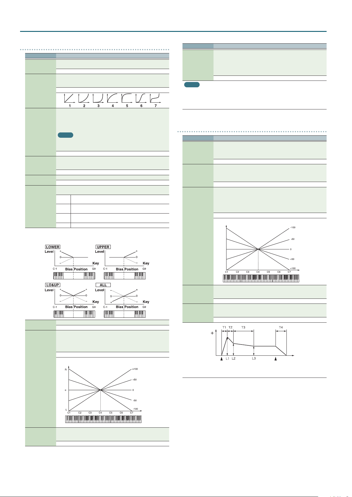
Bias Position
Bias Direction
Bias
Bias causes the volume to be aected by the keyboard position. This is useful for changing
volume through keyboard position (pitch) when playing acoustic instruments.
the volume balance between tones.
0–127
You can select from seven curves that determine how keyboard playing
strength will aect the volume. If you do not want the volume of the tone
to be aected by the force with which you play the key, set this to “FIXED.”
FIXED, 1–7
Set this when you want the volume of the tone to change depending on
the force with which you press the keys. Set this to a positive (+) value to
have the changes in tone volume increase the more forcefully the keys are
played; to make the tone play more softly as you play harder, set this to a
negative (-) value.
MEMO
If you wish to make adjustments to the entire patch while maintaining the
relative values of Level V-Sens among tones, adjust the Velocity Sens Oset
(p. 5). However, this setting is shared by the Cuto V-Sens (p. 9).
-63–+63
Adjusts the angle of the volume change that will occur in the selected Bias
Direction. Larger settings will produce greater change. Negative (-) values
will invert the change direction.
-100–+100
Species the key relative to which the volume will be modied.
C- –G9
Selects the direction in which change will occur starting from the Bias
Position.
The volume will be modied for the keyboard area below the
LWR
Bias Point.
The volume will be modied for the keyboard area above the
UPR
Bias Point.
The volume will be modied symmetrically toward the left and
L&U
right of the Bias Point.
ALL The volume changes linearly with the bias point at the center.
Parameter Value/Explanation
This setting causes panning to be alternated between left and right each
time a key is pressed. Higher settings will produce a greater amount
Alternate Pan
Depth
MEMO
When any value from Type “2”–”10” is selected for the Structure Type (p. 6) in the Pan
Keyfollow, Random Pan Depth, Alternate Pan Depth settings, the output of tones 1 and 2 are
joined in tone 2, and the output of tones 3 and 4 are joined in tone 4.
For this reason, tone 1 will follow the settings of tone 2, and tone 3 will follow the settings of
tone 4.
of change. “L” or “R” settings will reverse the order in which the pan will
alternate between left and right. For example if two tones are set to “L” and
“R” respectively, the panning of the two tones will alternate each time they
are played.
L63–0–63R
TVA ENV
Parameter Value/Explanation
This allows keyboard dynamics to aect the Time 1 of the TVA envelope.
If you want Time 1 to be speeded up for strongly played notes, set this
TVA-Env T1 V-Sens
TVA-Env T4 V-Sens
TVA-Env Time KF
parameter to a positive (+) value. If you want it to be slowed down, set this
to a negative (-) value.
-63–+63
The parameter to use when you want key release speed to control the
Time 4 value of the TVA envelope. If you want Time 4 to be speeded up
for quickly released notes, set this parameter to a positive (+) value. If you
want it to be slowed down, set this to a negative (-) value.
-63–+63
Use this setting if you want the TVA envelope times (Time 2–Time 4) to
be aected by the keyboard location. Based on the TVA envelope times
for the C4 key (center C), positive (+) settings will cause notes higher
than C4 to have increasingly shorter times, and negative (-) settings will
cause them to have increasingly longer times. Larger settings will produce
greater change.
-100–+100
Time
Tone Pan
2
Pan Keyfollow
Random Pan
Depth
Sets the pan of the tone. “L64” is far left, “0” is center, and “63R” is far right.
L64–0–63R
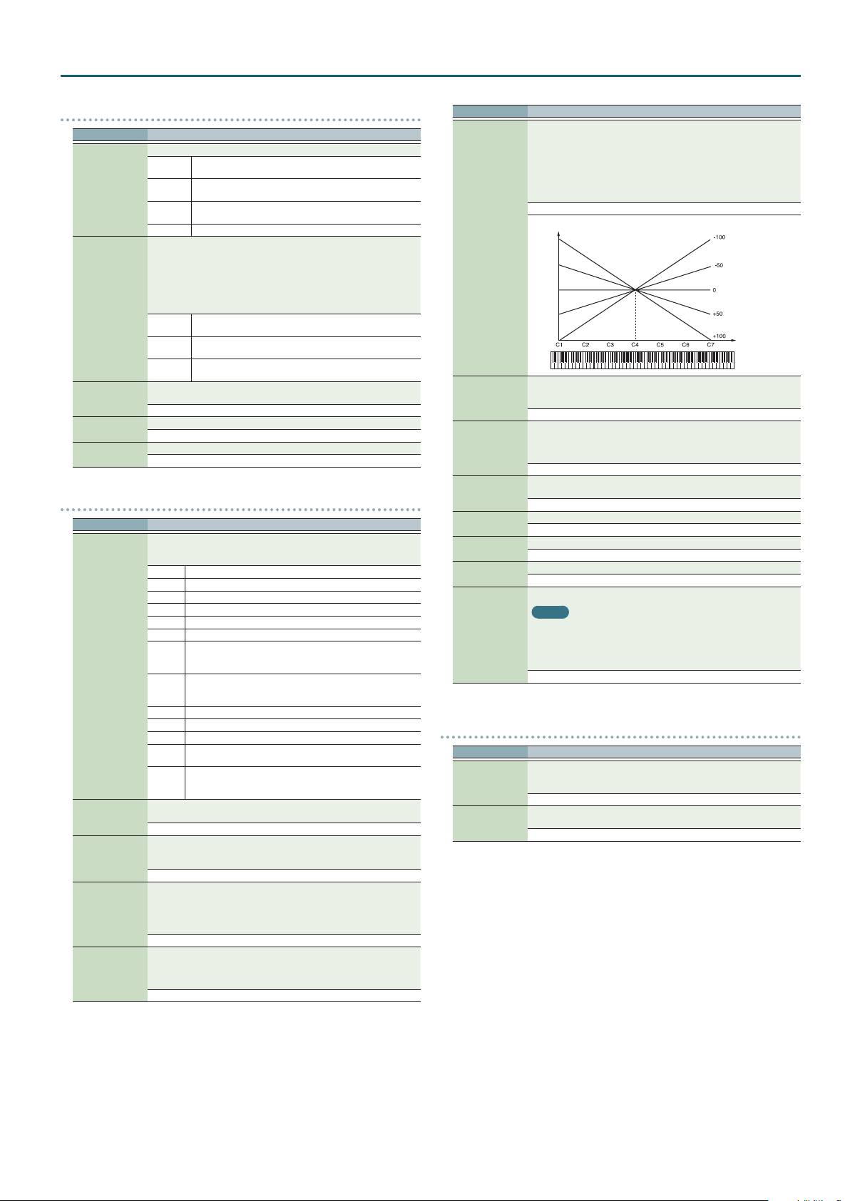
Use this parameter if you want key position to aect panning.
Positive (+) settings will cause notes higher than C4 key (center C) to be
panned increasingly further toward the right, and negative (-) settings will
cause notes higher than C4 key (center C) to be panned toward the left.
Larger settings will produce greater change.
-100–+100
Pan
Key
Use this parameter when you want the stereo location to change randomly
each time you press a key. Higher settings will produce a greater amount
of change.
0–63
TVA-Env Time 1–4
2
TVA-Env Level 1–3
Key
Specify the TVA envelope times (Time 1–Time 4). Higher settings will
lengthen the time until the next volume level is reached. (For example,
Time 2 is the time over which Level 1 will change to Level 2.)
0–127
Specify the TVA envelope levels (Level 1–Level 3). These settings specify
how the volume will change at each point, relative to the standard volume
(the Tone Level value specied in the TVA screen).
0–127
Level
Note on
T: Time L: Level
Note o
Time
10
Page 11
Patch Mode
OUTPUT
Parameter Value/Explanation
Species how the direct sound of each patch will be output.
MFX
Patch Output
Assign
Tone Output
Assign
Tone Output Level
Tone Chorus Send
Tone Reverb Send
L+R
L, R
TONE Outputs according to the settings for each tone.
Species how the direct sound of each tone will be output.
* If the Patch Output Assign is set to anything other than “TONE,” these
settings will be ignored.
* When the Structure Type (p. 6) has a setting of “2”–”10,” the outputs
of tones 1 and 2 will be combined with tone 2, and the outputs of tones
3 and 4 will be combined with tone 4. For this reason, tone 1 will follow
the settings of tone 2, and tone 3 will follow the settings of tone 4.
* Chorus and reverb are output in mono at all times.
MFX
L+R
L, R
Set the level of the signal that is sent to the output destination specied
by Patch Output Assign or Tone Output Assign.
0–127
Species the level of the signal sent to the chorus for each tone.
0–127
Species the level of the signal sent to the reverb for each tone.
0–127
LFO1, 2
Parameter Value/Explanation
Selects the waveform of the LFO.
* If you set this to “BD-U” or “BD-D,” you must turn the Key Trigger
parameter to “ON.” If this is “OFF,” it will have no eect.
SIN Sine wave
TRI Triangle wave
SAWU Sawtooth wave
SAWD Sawtooth wave (negative polarity)
SQR Square wave
RND Random wave
Waveform
Rate
2
Rate Detune
Oset
Delay Time
BD-U
BD-D
TRP Trapezoidal wave
S&H Sample & Hold wave (one time per cycle, LFO value is changed)
CHS Chaos wave
VSIN
STEP
Adjusts the modulation rate, or speed, of the LFO.
* This setting will be ignored if the Waveform parameter is set to “CHS.”
0–127, note
LFO Rate Detune makes subtle changes in the LFO cycle rate (Rate) each
time a key is pressed. Higher settings will cause greater change.
* This parameter is invalid when Rate is set to “note.”
0–127
Raises or lowers the LFO waveform relative to the central value (pitch or
cuto frequency). Positive (+) settings will move the waveform so that
modulation will occur from the central value upward. Negative (-) settings
will move the waveform so that modulation will occur from the central
value downward.
-100, -50, 0, +50, +100
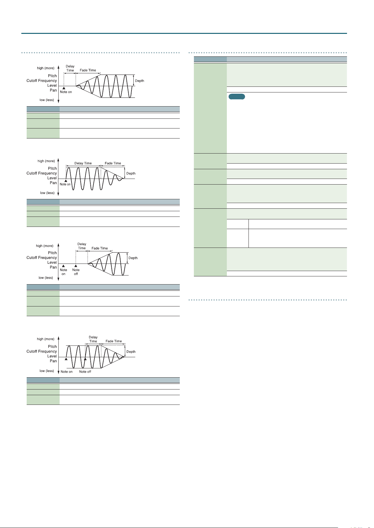
Delay Time (LFO Delay Time) species the time elapsed before the LFO
eect is applied (the eect continues) after the key is pressed (or released).
* After referring to “How to Apply the LFO” (p. 12), change the setting
until the desired eect is achieved.
0–127
Output in stereo through MFX. You can also apply chorus or
reverb to the sound that passes through MFX.
Output to the OUTPUT L (MONO) jack and OUTPUT R jack in
stereo without passing through MFX.
Output to the OUTPUT L (MONO) jack or OUTPUT R jack in
mono without passing through MFX.
Output in stereo through MFX. You can also apply chorus or
reverb to the sound that passes through MFX.
Output to the OUTPUT L (MONO) jack and OUTPUT R jack in
stereo without passing through MFX.
Output to the OUTPUT L (MONO) jack or OUTPUT R jack in
mono without passing through MFX.
Once the attack of the waveform output by the LFO is allowed
to develop in standard fashion, the waveform then continues
without further change.
Once the decay of the waveform output by the LFO is allowed
to develop in standard fashion, the waveform then continues
without further change.
Modied sine wave. The amplitude of a sine wave is randomly
varied once each cycle.
A waveform generated by the data specied by LFO Step 1–16.
This produces stepped change with a xed pattern similar to a
step modulator.
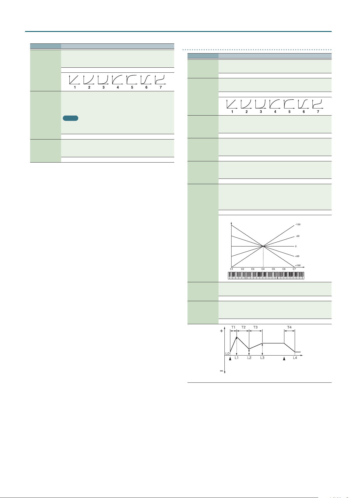
Parameter Value/Explanation
Adjusts the value for the Delay Time depending on the key position,
relative to the C4 key (center C). To decrease the time that elapses before
the LFO eect is applied (the eect is continuous) with each higher key
that is pressed in the upper registers, select a positive value; to increase
the elapsed time, select a negative value.
Larger settings will produce greater change. If you do not want the
elapsed time before the LFO eect is applied (the eect is continuous) to
change according to the key pressed, set this to “0.”
-100–+100
Time
Delay Time KF
Species how the LFO will be applied.
Fade Mode
Fade Time
Key Trigger
Pitch Depth
2
TVF Depth
2
TVA Depth
2
Pan Depth
2
* After referring to “How to Apply the LFO” (p. 12), change the setting
until the desired eect is achieved.
ON <, ON >, OFF <, OFF >
Species the time over which the LFO amplitude will reach the maximum
(minimum).
* After referring to “How to Apply the LFO” (p. 12), change the setting
until the desired eect is achieved.
0–127
Species whether the LFO cycle will be synchronized to begin when the
key is pressed (ON) or not (OFF).
OFF, ON
Species how deeply the LFO will aect pitch.
-63–+63
Species how deeply the LFO will aect the cuto frequency.
-63–+63
Species how deeply the LFO will aect the volume.
-63–+63
Species how deeply the LFO will aect the pan.
MEMO
When the Structure Type (p. 6) is set to any value from “2” through “10,”
the output of tones 1 and 2 will be combined into tone 2, and the output
of tones 3 and 4 will be combined into tone 4. This applies to the Pan
Depth settings. For this reason, tone 1 will follow the settings of tone 2,
and tone 3 will follow the settings of tone 4.
-63–+63
STEP LFO
Parameter Value/Explanation
When generating an LFO waveform from the data specied in LFO
Step Type
LFO Step 1–16
Step1–16, specify whether the level will change abruptly at each step
(TYP1) or will be connected linearly ( TYP2).
TYP1, TYP2
Species the data for the Step LFO. If the LFO Pitch Depth is +63, each +1
unit of the step data corresponds to a pitch of +50 cents.
-36–+36
Key
11
Page 12
Patch Mode
How to Apply the LFO
Apply the LFO gradually after the key is pressed
Parameter Value/Explanation
Fade Mode ON <
Delay Time
Fade Time
Apply the LFO immediately when the key is pressed, and then gradually begin to
decrease the eect
Parameter Value/Explanation
Fade Mode ON >
Delay Time The time that the LFO will continue after the keyboard is played.
Fade Time
Apply the LFO gradually after the key is released
The time from when the keyboard is played until the LFO begins to be
applied.
The time over which the LFO amplitude will reach the maximum after the
Delay Time has elapsed.
The time over which the LFO amplitude will reach the minimum after the
Delay Time has elapsed.
CTRL
Parameter Value/Explanation
When a loop waveform is selected, the sound will normally continue as
long as the key is pressed. If you want the sound to decay naturally even if
the key remains pressed, set this to “NOSUS.”
* If a one-shot type waveform is selected, it will not sustain even if this
parameter is set to “SUST.”
NOSUS, SUST
MEMO
5One-shot: These waveforms contain sounds that have short decays. A
Env Mode
Rx Bender
Rx Expression
Rx Hold-1
Rx Pan Mode
Redamper Sw
one-shot waveform records the initial rise and fall of the sound. Some
of the JUNO-DS’s one-shot waveforms are sounds that are complete
in themselves, such as percussive instrument sounds. The JUNO-DS
also contains many other one-shot waveforms that are elements of
other sounds. These include attack components such as piano-hammer
sounds and guitar fret noises.
5Looped: These waveforms include sounds with long decays as well
as sustained sounds. Loop waveforms repeatedly play back (loop) the
portion of the waveform after the sound has reached a relatively steady
state. The JUNO-DS’s looped waveforms also include components of
other sounds, such as piano-string resonant vibrations and the hollow
sounds of brass instruments.
For each tone, specify whether MIDI Pitch Bend messages will be received
(ON), or not (OFF).
OFF, ON
For each tone, specify whether MIDI Expression messages will be received
(ON), or not (OFF).
OFF, ON
For each tone, specify whether MIDI Hold-1 messages will be received (ON),
or not (OFF).
* If “NOSUS” is selected for Env Mode parameter, this setting will have no
eect.
OFF, ON
For each tone, specify how pan messages will be received.
* The channels cannot be set so as not to receive Pan messages.
CONT
K-ON
You can specify, on an individual tone basis, whether or not the sound
will be held when a Hold 1 message is received after a key is released, but
before the sound has decayed to silence. If you want to sustain the sound,
set this “ON.” When using this function, also set the Rx Hold-1 “ON.” This
function is eective for piano sounds.
OFF, ON
Whenever Pan messages are received, the stereo position of
the tone will be changed.
The pan of the tone will be changed only when the next
note is played. If a pan message is received while a note is
sounding, the panning will not change until the next key is
pressed.
Parameter Value/Explanation
Fade Mode OFF <
Delay Time
Fade Time
Apply the LFO from when the key is pressed until it is released, and gradually begin
to decrease the eect when the key is released
Parameter Value/Explanation
Fade Mode OFF >
Delay Time The time that the LFO will continue after the keyboard is released.
Fade Time
The time from when the keyboard is released until the LFO begins to be
applied.
The time over which the LFO amplitude will reach the maximum after the
Delay Time has elapsed.
The time over which the LFO amplitude will reach the minimum after the
Delay Time has elapsed.
Matrix control
Ordinarily, if you wanted to change tone parameters using an external MIDI device,
you would need to send System Exclusive messages—MIDI messages designed
exclusively for the JUNO-DS. However, System Exclusive messages tend to be
complicated, and the amount of data that needs to be transmitted can get quite
large.
For that reason, a number of the more typical of the JUNO-DS’s tone parameters
have been designed so they accept the use of Control Change (or other) MIDI
messages for the purpose of making changes in their values. This provides you with
a variety of means of changing the way patches are played. For example, you can
use the Pitch Bend lever to change the LFO cycle rate, or use the keyboard’s touch
to open and close a lter.
The function which allows you use MIDI messages to make these changes in
realtime to the tone parameters is called the Matrix control. Up to four Matrix
Controls can be used in a single patch.
To use the Matrix control, specify which MIDI message (Source) will be used to
control which parameter (Dest), and how greatly (Sens), and the tone to which the
eect is applied (Switch).
12
Page 13
Patch Mode
MTRX CTRL1–4
Parameter Value/Explanation
Sets the MIDI message used to change the tone parameter with the Matrix
Control.
OFF Matrix control will not be used.
CC01–32, 33–95 Controller numbers 1–32, 33–95
PITCH BEND Pitch Bend
AFTERTOUCH After touch
SYS CTRL1–SYS
Control 1–4
Source
5Although there are no MIDI messages for LFO 1 through TVA Envelope, they can be used as
Matrix Control. In this case, you can change the tone settings in realtime by playing patches.
5If you want to use common controllers for the entire JUNO-DS, select “SYS CTRL1”–”SYS
CTRL4.” MIDI messages used as System Control 1–4 are set with the System Ctrl 1–4 Source
(p. 34).
MEMO
5There are parameters that determine whether or not Pitch bend, Controller number 11
(Expression) and Controller number 64 (Hold 1) are received (p. 12). When these settings
are “ON,” and the MIDI messages are received, then when any change is made in the settings
of the desired parameter, the Pitch bend, Expression, and Hold 1 settings also change
simultaneously. If you want to change the targeted parameters only, then set these to “OFF.”
5There are parameters that let you specify whether specic MIDI messages will be received
for each channel in a performance (p. 20). When a patch with Matrix control settings
is assigned to a part, conrm that any MIDI messages used for the Matrix control will be
received. If the JUNO-DS is set up such that reception of MIDI messages is disabled, then the
Matrix control will not function.
Control Dest1–4
CTRL4
VELOCITY Velocity (pressure you press a key with)
KEY FOLLOW Key follow (keyboard position with C4 as 0)
* Velocity and Key follow correspond to Note messages.
TEMPO
LFO1, 2 LFO1, 2
PITCH ENV Pitch envelope
TVF ENV T VF envelope
TVA ENV T VA envelope
Matrix control destination selects the tone parameter that is to be
controlled when using the Matrix control. The following parameters can
be controlled. When not controlling parameters with the Matrix Control,
set this to “OFF.” Up to four parameters can be specied for each Matrix
Control, and controlled simultaneously.
OFF Matrix control will not be used.
Changing the pitch
PCH Changes the pitch.
Opening and closing the lter
CUT Changes the cuto frequency.
RES
Changing the volume and pan
LEV Changes the volume level.
PAN Changes the pan.
Changing how the eects are applied
DRY Changes the volume of the original sound.
CHO Changes the amount of chorus.
REV Changes the amount of reverb.
Applying LFO to modulate sounds
PIT-LFO1, 2 Changes the vibrato depth.
TVF-LFO1, 2 Changes the wah depth.
TVA-LFO1, 2 Changes the tremolo depth.
PAN-LFO1, 2 Changes the eect that the LFO will have on pan.
LFO-RATE
Changing the Pitch Envelope
PIT-ATK Changes the Env Time 1of the pitch envelope.
PIT-DCY
PIT-REL Changes the Env Time 4 of the pitch envelope.
Changing the TVF Envelope
TVF-ATK Changes the Env Time 1 of the TVF envelope.
TVF-DCY
TVF-REL Changes the Env Time 4 of the TVF envelope.
Changing the TVA Envelope
T VA-AT K Changes the Env Time 1 of the TVA envelope.
TVA-DCY
TVA-REL Changes the Env Time 4 of the TVA envelope.
Splitting tones that are played
TMT
MIDI messages used as common matrix controls.
The specied tempo (sequencer tempo) or the tempo
of an external MIDI sequencer.
Emphasizes the overtones in the region of the cuto
frequency, adding character to the sound.
Changes the speed of the LFO cycles.
The speed will not change if LFO Rate is set to “note.”
Changes the Env Time 2 and Env Time 3 of the pitch
envelope.
Changes the Env Time 2 and Env Time 3 of the TVF
envelope.
Changes the Env Time 2 and Env Time 3 of the TVA
envelope.
5If the Matrix control is used to split tones, set the
TMT Velocity Control to “OFF,” and the TMT Control
Switch to “ON” (p. 7).
5If the Matrix control is used to split tones, we
recommend setting the Matrix control Sens to “+63.”
Selecting a lower value may prevent switching of
the tones. Furthermore, if you want to reverse the
eect, set the value to “-63.”
5If you want to use matrix control to switch smoothly
between tones, use the Velo Fade Lower and Velo
Fade Upper (p. 7). The higher the values set, the
smoother the switch is between the tones.
Parameter Value/Explanation
Changing the depth of frequency modulation for FXM
FXM
Changing specic MFX parameters
MFX1–4
Sets the amount of the Matrix Control’s eect that is applied.
If you wish to modify the selected parameter in a positive (+) direction—i.e.,
a higher value, toward the right, or faster etc. —from its current setting,
select a positive (+) value. If you wish to modify the selected parameter in
Control Sens1–4
Control Switch1–4
a negative (-) direction—i.e., a lower value, toward the left, or slower etc.
—from its current setting, select a negative (-) value.
For either positive or negative settings, greater absolute values will allow
greater amounts of change. Set this to “0” if you don’t want to apply the
eect.
-63–+63
Selects the tone to which the eect is applied when using the Matrix
Control.
OFF The eect will not be applied.
ON The eect will be applied.
REVS The eect will be applied in reverse.
Change the parameter that was specied by MFX
Control 1–4 Assign.
* If you have not made the necessary settings for
using the MFX, the MFX will not be applied even
if you attempt to control it as a Matrix control
destination.
13
Page 14
Patch Mode
Drum Kit Parameters
MEMO
A drum kit consists of a percussion instrument sound (tone) assigned to each key. The tone that’s assigned to each key consists of a combination of up to four waves. Drum Kit
Edit lets you edit the settings of the tone that’s assigned to each key.
COMMON
Parameter Value/Explanation
A0–C8
(Tone name)
Drum Kit Level
Tone Name
Assign Type
Mute Group
Tone Env Mode
Tone Pitch Bend
Range
Tone Rx
Expression
Tone Rx Hold-1
Rx Pan Mode
One Shot Mode
Species the key to which the tone you want to edit is assigned.
* You can also press a key to select this.
Sets the volume of the drum kit.
0–127
Changes the name (tone name) of the tone that’s assigned to the specied
key.
Refer to “Editing the tone name” (p. 14).
Sets the way sounds are played when the same key is pressed a number of
times.
Layer the sound of the same keys. Even with continuous
sounds where the sound plays for an extended time, such as
MULTI
with crash cymbals, the sounds are layered, without previously
played sounds being eliminated.
Only one sound can be played at a time when the same key is
pressed. With continuous sounds where the sound plays for
SINGLE
an extended time, the previous sound is stopped when the
following sound is played.
On an actual acoustic drum set, an open hi-hat and a closed hi-hat sound
can never occur simultaneously. To reproduce the reality of this situation,
you can set up a Mute Group.
The Mute Group function allows you to designate two or more tones that
are not allowed to sound simultaneously. Up to 31 Mute Groups can be
used. Tones that are not belong to any such group should be set to “OFF.”
OFF, 1–31
When a loop waveform (p. 12) is selected, the sound will normally
continue as long as the key is pressed. If you want the sound to decay
naturally even if the key remains pressed, set this to “NO-SUS.”
* If a one-shot type waveform (p. 12) is selected, it will not sustain even
if this parameter is set to “SUSTAIN.”
NO-SUS, SUSTAIN
Species the amount of pitch change in semitones (4 octaves) that will
occur when the pitch bend lever is moved. The amount of change when
the lever is tilted is set to the same value for both left and right sides.
0–48
For each tone, specify whether MIDI Expression messages will be received
(ON), or not (OFF).
OFF, ON
For each tone, specify whether MIDI Hold-1 messages will be received (ON),
or not (OFF).
* If “NO-SUS” is selected for Tone Env Mode (p. 14), this setting will have
no eect.
OFF, ON
For each tone, specify how pan messages will be received.
* The channels cannot be set so as not to receive Pan messages.
Whenever Pan messages are received, the stereo position of
CONT
the tone will be changed.
The pan of the tone will be changed only when the next note
K-ON
is played. If a pan message is received while a note is sounding,
the panning will not change until the next key is pressed.
The sound will play back until the end of the waveform (or the end of the
envelope, whichever comes rst). The result will be the same as when the
envelope’s Tone Env Mode (p. 14) is set to “NO-SUS.”
OFF, ON
Editing the tone name
Move the cursor to “Tone Name,” and press the [ENTER] button.
1.
The DRUM KIT TONE NAME screen appears.
Assign a tone name
2.
Operation Explanation
[K] [J] buttons Move the cursor.
Value dial, [–] [+] buttons Select the character.
[I] [H] buttons Switch between uppercase and lowercase.
Inserting/ Deleting Characters
While entering a name, press the [MENU] button.
1.
The NAME MENU window appears. The window closes if you press the button
once again.
Move the cursor to “INSERT” or “DELETE,” and press the [ENTER] button.
2.
Function Explanation
INSERT Press the [ENTER] button to insert a space (blank) at the cursor location.
DELETE
Press the [ENTER] button to delete the character at the cursor location;
subsequent characters will be moved forward to ll the gap.
WAVE
Parameter Value/Explanation
1– *4
*
Wave Group
Wave No. L (Mono)
Wave No. R
Wave Gain
Wave Tempo Sync
Wave FXM Switch
Wave FXM Color
Wave FXM Depth
Wave Coarse Tune
Wave Fine Tune
Wave Level
Wave Pan
Wave Random Pan
Sw
Wave Alter Pan Sw
Specify the on/o status of tones 1–4. If a tone is on, a “(” mark is shown.
OFF, ON
Select the groups containing the Waves comprising the tone.
INTA, B Waveforms stored in internal
EXP Waveforms for expansion sounds
Selects the Waves comprising the tone. Along with the Wave number, the
Wave name appears at the lower part of the display.
When in mono, only the left side (L) is specied. When in stereo, the right
side (R) is also specied.
OFF, 1–2402 (The upper limit will depend on the wave group.)
Sets the gain (amplication) of the waveform. The value changes in 6 dB
(decibel) steps—an increase of 6 dB doubles the waveform’s gain.
-6, 0, +6, +12
When you wish to synchronize a Phrase Loop to the clock (tempo), set this
to “ON.”
OFF, ON
Sets whether FXM will be used (ON) or not (OFF).
OFF, ON
Species how FXM will perform frequency modulation. Higher settings
result in a grainier sound, while lower settings result in a more metallic
sound.
1–4
Species the depth of the modulation produced by FXM.
0–16
Adjusts the pitch of the waveform’s sound up or down in semitone steps (±4
octaves).
-48–+48
Adjusts the pitch of the waveform’s sound up or down in 1-cent steps (±50
cents).
-50–+50
Sets the volume of the waveform.
0–127
Species the pan of the waveform. “L64” is far left, “0” is center, and “63R” is
far right.
L64–0–63R
Use this setting to cause the waveform’s panning to change randomly
each time a key is pressed (ON) or not (OFF).
* The range of the panning change is set by the Random Pan Depth
(p. 16).
OFF, ON
This setting causes panning of the waveform to be alternated between left
and right each time a key is pressed.
OFF Pan does not change.
ON
REVS The waveform is panned in reverse.
WMT
Parameter Value/Explanation
WMT Velocity Control determines whether a dierent tone is played or not
depending on the force with which the key is played (velocity).
WMT Velocity
Control
Velo Fade Upper,
Lower
Velo Range
Upper, Lower
OFF Waveforms are not velocity-switched.
ON
RANDOM
This determines what will happen to the tone’s level when the tone is
played at a velocity Upper/lower than its specied velocity range. Higher
settings produce a more gradual change in volume. If you want notes
played outside the specied key velocity range to not be sounded at all,
set this to “0.”
0–127
This sets the highest/lowest velocity at which the waveform will sound.
Make these settings when you want dierent waveforms to sound in
response to notes played at dierent strengths.
* If you attempt to set the Lower velocity limit above the Upper, or the
Upper below the Lower, the other value will automatically be adjusted
to the same setting.
(Upper) LOWER–127, (Lower) 1–UPPER
The waveform is panned according to the Alternate Pan Depth
(p. 16) setting.
Waveforms are switched according to the keyboard playing
velocity.
The waveform’s constituent tones will sound randomly,
regardless of the velocity.
When you’ve specied the name, press the [ENTER] button.
3.
14
Page 15

Patch Mode
Parameter Value/Explanation
Level
Fade Lower
Range Lower Range Upper
PITCH
Parameter Value/Explanation
Tone Coarse Tune
Tone Fine Tune
Tone Random
Pitch Depth
Selects the pitch at which a tone sounds.
C- –G9
Adjusts the pitch of the tone’s sound up or down in 1-cent steps (±50
cents).
-50–+50
Species the width of random pitch deviation that will occur each time a
key is pressed. If you do not want the pitch to change randomly, set this to
“0.” These values are in units of cents (1/100th of a semitone).
0–1200
PITCH ENV
Parameter Value/Explanation
Adjusts the eect of the Pitch Envelope. Higher settings will cause the
Pitch Env Depth
Pitch Env V-Sens
Pitch Env T1
V-Sens
Pitch Env T4
V-Sens
Pitch Env Time 1–4
Pitch Env Level
0–4
pitch envelope to produce greater change. Negative (-) settings will invert
the shape of the envelope.
-12–+12
Keyboard playing dynamics can be used to control the depth of the pitch
envelope. If you want the pitch envelope to have more eect for strongly
played notes, set this parameter to a positive (+) value. If you want the
pitch envelope to have less eect for strongly played notes, set this to a
negative (-) value.
-63–+63
This allows keyboard dynamics to aect the Time 1 of the Pitch envelope.
If you want Time 1 to be speeded up for strongly played notes, set this
parameter to a positive (+) value. If you want it to be slowed down, set this
to a negative (-) value.
-63–+63
Use this parameter when you want key release speed to aect the Time
4 value of the pitch envelope. If you want Time 4 to be speeded up for
quickly released notes, set this parameter to a positive (+) value. If you
want it to be slowed down, set this to a negative (-) value.
-63–+63
Specify the pitch envelope times (Time 1–Time 4). Higher settings will
result in a longer time until the next pitch is reached. (For example, Time 2
is the time over which the pitch changes from Level 1 to Level 2.)
0–127
Specify the pitch envelope levels (Level 0–Level 4).
It determines how much the pitch changes from the reference pitch (the
value set with Coarse Tune or Fine Tune on the Pitch screen) at each point.
Positive (+) settings will cause the pitch to be higher than the standard
pitch, and negative (-) settings will cause it to be lower.
-63–+63
Pitch
Note on
Fade Upper
Note o
Velocity
Time
TVF
Parameter Value/Explanation
Selects the type of lter. A lter cuts or boosts a specic frequency region
to change a sound’s brightness, thickness, or other qualities.
* If you set “LPF2” or “LPF3,” the setting for the Resonance will be ignored
(p. 15).
OFF No lter is used.
LPF
BPF
HPF
PKG
LPF2
Filter Type
LPF3
Selects the frequency at which the lter begins to have an eect on the
waveform’s frequency components.
“LPF/LPF2/LPF3” selected for the Filter Type
Lower cuto frequency settings reduce a tone’s upper harmonics for a
more rounded, warmer sound. Higher settings make it sound brighter.
“BPF” selected for the Filter Type
Harmonic components will change depending on the TVF Cuto
Cuto Frequency
Resonance
Cuto V-Curve
Frequency setting. This can be useful when creating distinctive sounds.
“HPF” selected for the Filter Type
Higher Cuto Frequency settings will reduce lower harmonics to
emphasize just the brighter components of the sound.
“PKG” selected for the Filter Type
The harmonics to be emphasized will vary depending on Cuto Frequency
setting.
0–127
Emphasizes the portion of the sound in the region of the cuto frequency,
adding character to the sound. Excessively high settings can produce
oscillation, causing the sound to distort.
0–127
Selects one of the following seven curves that determine how keyboard
playing dynamics (velocity) inuence the cuto frequency.
Set this to “FIXED” if you don’t want the Cuto frequency to be aected by
the keyboard velocity.
FIXED, 1–7
Low Pass Filter. This reduces the volume of all frequencies above
the cuto frequency in order to round o, or un-brighten the
sound. This is the most common lter used in synthesizers.
Band Pass Filter. This leaves only the frequencies in the region of
the cuto frequency, and cuts the rest. This can be useful when
creating distinctive sounds.
High Pass Filter. This cuts the frequencies in the region below the
cuto frequency. This is suitable for creating percussive sounds
emphasizing their higher tones.
Peaking Filter. This emphasizes the frequencies in the region of
the cuto frequency. You can use this to create wah-wah eects
by employing an LFO to change the cuto frequency cyclically.
Low Pass Filter 2. Although frequency components above the
cuto frequency are cut, the sensitivity of this lter is half that of
the LPF. This makes it a comparatively warmer low pass lter. This
lter is good for use with simulated instrument sounds such as
the acoustic piano.
Low Pass Filter 3. Although frequency components above the
cuto frequency are cut, the sensitivity of this lter changes
according to the cuto frequency. While this lter is also good
for use with simulated acoustic instrument sounds, the nuance
it exhibits diers from that of the LPF2, even with the same TVF
Envelope settings.
T: Time L: Level
Cuto V-Sens
Resonance V-Sens
Use this parameter when changing the cuto frequency to be applied as a
result of changes in playing velocity. If you want strongly played notes to
raise the cuto frequency, set this parameter to positive (+) settings. If you
want strongly played notes to lower the cuto frequency, use negative (-)
settings.
-63–+63
This allows keyboard velocity to modify the amount of Resonance. If you
want strongly played notes to have a greater Resonance eect, set this
parameter to positive (+) settings. If you want strongly played notes to
have less Resonance, use negative (-) settings.
-63–+63
15
Page 16
Patch Mode
TVF ENV
Parameter Value/Explanation
Species the depth of the TVF envelope. Higher settings will cause the TVF
TVF Env Depth
TVF Env V-Curve
TVF Env V-Sens
TVF Env T1 V-Sens
TVF Env T4 V-Sens
TVF Env Time 1–4
TVF Env Level 0–4
envelope to produce greater change. Negative (-) settings will invert the
shape of the envelope.
-63–+63
Selects one of the following 7 curves that will determine how keyboard
playing dynamics will aect the TVF envelope. Set this to “FIXED” if you
don’t want the TVF Envelope to be aected by the keyboard velocity.
FIXED, 1–7
Species how keyboard playing dynamics will aect the depth of the
TVF envelope. Positive (+) settings will cause the TVF envelope to have a
greater eect for strongly played notes, and negative (-) settings will cause
the eect to be less.
-63–+63
This allows keyboard dynamics to aect the Time 1 of the TVF envelope.
If you want Time 1 to be speeded up for strongly played notes, set this
parameter to a positive (+) value. If you want it to be slowed down, set this
to a negative (-) value.
-63–+63
The parameter to use when you want key release speed to control the
Time 4 value of the TVF envelope. If you want Time 4 to be speeded up
for quickly released notes, set this parameter to a positive (+) value. If you
want it to be slowed down, set this to a negative (-) value.
-63–+63
Specify the TVF envelope times (Time 1–Time 4). Higher settings will
lengthen the time until the next cuto frequency level is reached. (For
example, Time 2 is the time over which Level 1 will change to Level 2.)
0–127
Specify the TVF envelope levels (Level 0–Level 4). These settings specify
how the cuto frequency will change at each point, relative to the
standard cuto frequency (the cuto frequency value specied in the TVF
screen).
0–127
Cuto
Frequency
Note on
T: Time L: Level
TVA
Parameter Value/Explanation
Sets the volume of the tone. Use this parameter to adjust the volume
Tone Level
Level V-Curve
Level V-Sens
Tone Pan
Random Pan
Depth
Alternate Pan
Depth
balance between tones.
0–127
You can select from seven curves that determine how keyboard playing
strength will aect the volume. If you do not want the volume of the tone
to be aected by the force with which you press the key, select “FIXED.”
FIXED, 1–7
Set this when you want the volume of the tone to change depending on
the force with which you press the keys. Set this to a positive (+) value to
have the changes in tone volume increase the more forcefully the keys are
played; to make the tone play more softly as you play harder, set this to a
negative (-) value.
-63–+63
Sets the pan for the tone. “L64” is far left, “0” is center, and “63R” is far right.
L64–0–63R
Use this parameter when you want the stereo location to change randomly
each time you press a key.
Higher settings will produce a greater amount of change.
* This will aect only waves whose Wave Random Pan Sw (p. 14) is “ON.”
0–63
This setting causes panning to be alternated between left and right each
time a key is pressed. Higher settings will produce a greater amount
of change. “L” or “R” settings will reverse the order in which the pan will
alternate between left and right. For example if two tones are set to “L” and
“R” respectively, the panning of the two tones will alternate each time they
are played.
* This will aect only waves whose Wave Alter Pan Sw (p. 14) is “ON” or
“REVS.”
L63–0–63R
Note o
Time
Parameter Value/Explanation
Corrects for the volume of the tone.
This parameter is set by the key-based controller system exclusive
Relative Level
message. Normally, you should leave it set to 0.
* If the Tone Level is set to 127, the volume will not increase beyond that
point.
-64–+63
TVA-ENV
Parameter Value/Explanation
This allows keyboard dynamics to aect the Time 1 of the TVA envelope.
If you want Time 1 to be speeded up for strongly played notes, set this
TVA-Env T1 V-Sens
TVA-Env T4 V-Sens
TVA-Env Time 1–4
TVA-Env Level 1–3
parameter to a positive (+) value. If you want it to be slowed down, set this
to a negative (-) value.
-63–+63
The parameter to use when you want key release speed to control the
Time 4 value of the TVA envelope. If you want Time 4 to be speeded up
for quickly released notes, set this parameter to a positive (+) value. If you
want it to be slowed down, set this to a negative (-) value.
-63–+63
Specify the TVA envelope times (Time 1–Time 4). Higher settings will
lengthen the time until the next volume level is reached. (For example,
Time 2 is the time over which Level 1 will change to Level 2.)
0–127
Specify the TVA envelope levels (Level 1–Level 3). These settings specify
how the volume will change at each point, relative to the standard volume
(the Tone Level value specied in the TVA screen).
0–127
Level
Note on
T: Time L: Level
OUTPUT
Parameter Value/Explanation
Species for each drum kit how the direct sound will be output.
MFX
Rhythm Output
Assign
Tone Output
Assign
Tone Output Level
Tone Chorus Send
Tone Reverb Send
L+R
L, R
TONE Outputs according to the settings for each tone.
Species how the direct sound of each tone will be output.
* If the Rhythm Output Assign is set to anything other than “TONE,” these
settings will be ignored.
* Chorus and reverb are output in mono at all times.
MFX
L+R
L, R
Set the level of the signal that is sent to the output destination specied
by Patch Output Assign or Tone Output Assign.
0–127
Species the level of the signal sent to the chorus for each tone.
0–127
Species the level of the signal sent to the reverb for each tone.
0–127
Time
Note o
Output in stereo through MFX. You can also apply chorus or
reverb to the sound that passes through MFX.
Output to the OUTPUT L (MONO) jack and OUTPUT R jack in
stereo without passing through MFX.
Output to the OUTPUT L (MONO) jack or OUTPUT R jack in mono
without passing through MFX.
Output in stereo through MFX. You can also apply chorus or
reverb to the sound that passes through MFX.
Output to the OUTPUT L (MONO) jack and OUTPUT R jack in
stereo without passing through MFX.
Output to the OUTPUT L (MONO) jack or OUTPUT R jack in mono
without passing through MFX.
16
Page 17
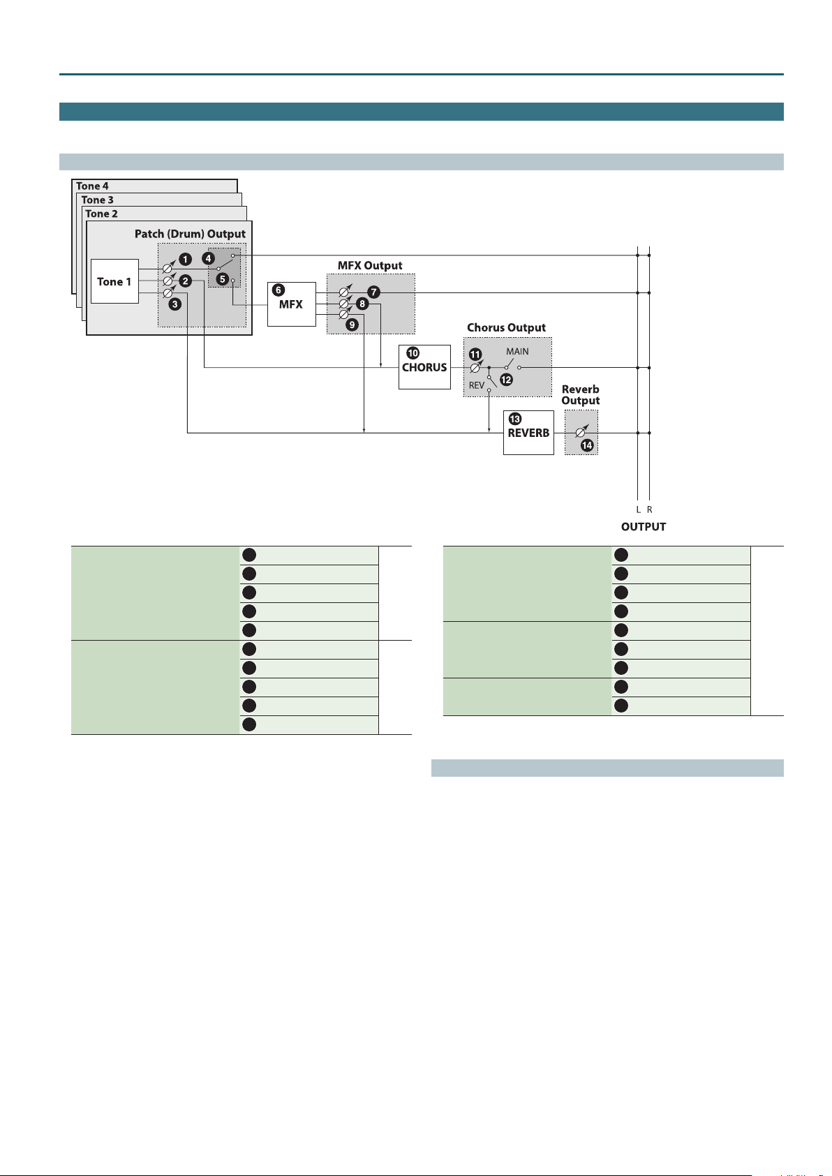
Eects Edit
In Patch mode you can use multi eects (MFX), chorus, and reverb.
Signal Flow
Patch Mode
When a patch is selected
Make these settings in the “OUTPUT” tab of
the PATCH EDIT screen.
When a drum kit is selected
Make these settings in the “OUTPUT” tab of
the DRUM KIT EDIT screen.
Tone Output Level
1
Tone Chorus Send
2
Tone Reverb Send
3
Patch Output Assign
4
Tone Output Assign
5
Tone Output Level
1
Tone Chorus Send
2
Tone Reverb Send
3
Rhythm Output Assign
4
Tone Output Assign
5
p. 11
p. 16
MFX Type
6
Output Level
Make these settings in the “MFX” tab of the
EFFECTS EDIT screen.
Make these settings in the “CHORUS” tab of
the EFFECTS EDIT screen.
Make these settings in the “REVERB” tab of the
EFFECTS EDIT screen.
7
Chorus Send Level
8
Reverb Send Level
9
Chorus Type
10
Chorus Level
11
Output Select
12
Reverb Type
13
Reverb Level
14
Procedure
Press the [SAMPLE IMPORT] button and [DAW CONTROL] button
1.
simultaneously.
The EDIT MENU screen appears.
Move the cursor to “EFFECTS EDIT,” and press the [ENTER] button.
2.
The EFFECTS EDIT screen appears.
Move the cursor to tab, and use the [K] [J] buttons to switch the pages.
3.
Move the cursor to the parameter that you want to edit, and use the value
4.
dial to change the value.
To save the edited settings, perform the operation “Saving Your Settings
5.
(Write)” (refer to owner’s manual).
p. 18
17
Page 18
Patch Mode
Eects Parameters
MFX
Parameter Value/Explanation
Turns MFX on/o, and species the type of MFX that is used. If MFX is on,
shows a “(” mark.
MFX Type
Parameters for
each MFX type
Output Level
Chorus Send Level
Reverb Send Level
8
* For details on MFX, refer to “MFX Parameters (MFX, MFX1–3)” (p. 40).
00: THRU–80: BIT CRUSHER
Edit the parameters of the MFX type you’ve selected.
* Refer to “MFX Parameters (MFX, MFX1–3)” (p. 40).
Adjusts the volume of the sound that has passed through the MFX.
If you’re applying a MFX, this species the depth of the MFX. If you’re not
applying a MFX, this species the volume of the original sound.
0–127
Species the level of the signal sent to the chorus.
0–127
Species the level of the signal sent to the reverb.
0–127
MFX control
If you wanted to change the volume of MFX sounds, the delay time of Delay, and
the like, using an external MIDI device, you would need to send System Exclusive
messages-MIDI messages designed exclusively for the JUNO-DS. However, System
Exclusive messages tend to be complicated, and the amount of data that needs to
be transmitted can get quite large.
For that reason, a number of the more typical of the JUNO-DS’s MFX parameters
have been designed so they accept the use of Control Change (or other) MIDI
messages for the purpose of making changes in their values. For example, you can
use the Pitch Bend lever to change the amount of distortion, or use the keyboard’s
touch to change the delay time of Delay.
The parameters that can be changed are predetermined for each type of MFX;
among the parameters described in “MFX parameters” (p. 40), these are indicated
by a “#.”
The function that allows you use MIDI messages to make these changes in realtime
to the MFX parameters is called the MFX control. Up to four MFX controls can be
used in a single patch/drum kit/performance.
When the MFX control is used, you can select the amount of control (Sens) applied,
the parameter selected (Destination), and the MIDI message used (Source).
MEMO
By using the Matrix control instead of the MFX control, you can also change the
parameters of some popular MFX in realtime (p. 12).
CHORUS
Parameter Value/Explanation
Turns Chorus on/o, and species the type of chorus that is used. If Chorus
is on,
8
Chorus Type
Parameters for
each chorus type
Output Select
Chorus Level
00: OFF Neither chorus or delay is used.
01: CHORUS Chorus is used.
02: DELAY Delay is used.
03: GM2 CHORUS GM2 chorus
Set the parameters of the selected chorus type.
* Refer to “Chorus Parameters” (p. 58).
Species how the sound routed through chorus will be output.
MAIN Output to the OUTPUT jacks in stereo.
REV Output to reverb in mono.
M+R
Adjusts the volume of the sound that has passed through chorus.
0–127
REVERB
Parameter Value/Explanation
Turns Reverb on/o, and species the type of reverb that is used. If Reverb
is on,
8
00: OFF Reverb is not used.
01: REVERB Normal reverb
Reverb Type
Parameters for
each reverb type
Reverb Level
02: SRV ROOM
03: SRV HALL
04: SRV PLATE
05: GM2 REVERB GM2 reverb
Set the parameters of the selected reverb type.
* Refer to “Reverb Parameters” (p. 58).
Adjusts the volume of the sound that has passed through reverb.
0–127
shows a “(” mark.
shows a “(” mark.
Output to the OUTPUT jacks in stereo, and to
reverb in mono.
This reverb simulates typical room acoustic
reections.
This reverb simulates typical concert hall acoustic
reections.
This reverb simulates a reverb plate, a popular
type of articial reverb unit that derives its sound
from the vibration of a metallic plate.
MFX CTRL
Parameter Value/Explanation
Sets the MIDI message used to change the MFX parameter with the MFX
control.
OFF MFX control will not be used.
Source 1–4
Destination 1–4
Sens 1–4
CC01–31, 33–95 Controller numbers 1–31, 33–95
PITCH BEND Pitch bend
AFTERTOUCH After touch
SYS CTRL1–4 Use the System Control 1–4 Source setting (p. 34).
Sets the MFX parameters to be controlled with the Source 1–4. The MFX
parameters available for control will depend on the MFX Type.
* Refer to “MFX Parameters (MFX, MFX1–3)” (p. 40).
Species the depth of MFX control.
Specify a positive (+) value if you want to change the value of the assigned
destination in a positive direction (larger, toward the right, faster, etc.), or
specify a negative value (-) if you want to change the value in a negative
direction (smaller, toward the left, slower, etc.).
Larger values will allow a greater amount of control.
-63–+63
18
Page 19
Performance Mode
Performance Edit
MEMO
PERFORMANCE EDIT and PART EDIT have the same parameters in common.
Procedure
Press the [PATCH/PERFORM] button to make it light.
1.
Select a performance that you want to edit.
2.
Press the [SAMPLE IMPORT] button and [DAW CONTROL] button
3.
simultaneously.
The EDIT MENU screen appears.
Move the cursor to “PERFORMANCE EDIT,” and press the [ENTER] button.
4.
The PERFORM EDIT screen appears.
MEMO
5In the PERFORM EDIT screen, you can use pads [1]–[8] to select the part that
you want to edit. If you hold down the [SHIFT] button and press a pad [1]–[8], a
part 9–16 is selected.
5In the PERFORM EDIT screen, press the [MENU] button to open the INIT MENU
window. Select “PERFORM” or “PART” and press the [ENTER] button to initialize
the selected performance or part.
Performance Parameters
Move the cursor to tab, and use the [K] [J] buttons to switch the pages.
5.
Move the cursor to the parameter that you want to edit, and use the value
6.
dial to change the value.
To save the edited settings, perform the operation “Saving Your Settings
7.
(Write)” (refer to owner’s manual).
PATC H
Parameter Value/Explanation
Type
Bank
Number
Kbd
Sets the assignment of a patch (Pat) or drum kit (Drm) to each of the parts.
Pat, Drm
Selects the group to which the desired patch or drum kit belongs.
DS (DS tone), PRST (Preset), GM (GM2 tone), EXP (expansion sounds), USER
Selects the desired patch or drum kit by its number.
0001–
Species, for each part, whether or not the keyboard controller section will
be connected to the internal sound generator.
OFF, ON
LEVEL/CH
Parameter Value/Explanation
Turns on the part that you want to solo. Parts other than the soloed part
Solo
Mute
Level
Pan
RxCh
RxSw
are not heard.
OFF, ON
Species whether each part’s performance is temporarily muted (ON) or
not muted (OFF).
* The Mute parameter does not turn the part o; it mutes the sound by
minimizing the volume. Therefore, the part still receives MIDI messages.
OFF, ON
Adjust the volume of each part. This setting’s main purpose is to adjust the
volume balance between parts.
0–127
Adjust the pan of each part. “L64” is far left, “0” is center, and “63R” is far
right.
L64–0–63R
Species the MIDI receive channel for each part.
1–16
For each part, specify whether MIDI messages will be received (ON), or not
(OFF).
If this is “OFF,” the part will not respond. Normally, you should leave this
“ON,” but you can turn it “OFF” when you do not want a specic part to be
playing during song playback.
OFF, ON
OUTPUT
Parameter Value/Explanation
Species for each part how the direct sound will be output.
MFX
Out
Sel
Lev
Cho
L+R
L, R
PATC H Outputs according to the settings for patch.
Of the three types of MFX that can be used simultaneously, specify which
MFX will be used.
1–3 (MFX1–MFX3)
Set the level of the signal that is sent to the output destination specied
by Part Output Assign.
0–127
Sets the level of the signal sent to chorus for each part.
0–127
Output in stereo through MFX. You can also apply chorus or
reverb to the sound that passes through MFX.
Output to the OUTPUT L (MONO) jack and OUTPUT R jack in
stereo without passing through MFX.
Output to the OUTPUT L (MONO) jack or OUTPUT R jack in
mono without passing through MFX.
Parameter Value/Explanation
Rev
1–3
C
R
Sets the level of the signal sent to reverb for each part.
0–127
Turn MFX 1–3 on/o for each part. If turned on, a “(” mark appears.
O (–), On (
Turn Chorus on/o for each part. If turned on, a “(” mark appears.
O (–), On (
Turn Reverb on/o for each part. If turned on, a “(” mark appears.
O (–), On (
PITCH
Parameter Value/Explanation
Adjusts the pitch of the part’s sound up or down in units of an octave (±3
Oct
Crs
Fine
Mono
Legt
Bend
Port
Time
octaves).
* Note that when a rhythm set is assigned to a part, you cannot modify
the Octave Shift.
-3–+3
Adjusts the pitch of the part’s sound up or down in semitone steps (±4
octaves).
-48–+48
Adjusts the pitch of the part’s sound up or down in 1-cent steps (±50
cents).
-50–+50
Set this parameter to “MONO” when the patch assigned to the part is to
be played monophonically, or to “POLY” when the patch is to be played
polyphonically. If you want to use the Mono/Poly setting of the patch
assigned to the part (p. 5), set this to “PAT.”
* This setting is ignored for parts to which a drum kit is assigned.
MONO, POLY, PAT
Turn this parameter “ON” when you want to use the Legato feature and
“OFF” when you don’t. If you want to use the Legato Switch setting of the
patch assigned to the part (p. 5), set this to “PAT.”
* This setting is ignored for parts to which a drum kit is assigned.
OFF, ON, PAT
Species the amount of pitch change in semitones (2 octaves) that will
occur when the Pitch Bend Lever is moved. The amount of change when
the lever is tilted is set to the same value for both left and right sides. If you
want to use the Pitch Bend Range setting of the patch assigned to the part
(p. 7), set this to “PAT.”
0–24, PAT
Turn this parameter “ON” when you want to apply Portamento and “OFF”
when you don’t. If you want to use the Portamento Switch setting of the
patch assigned to the part (p. 5), set this to “PAT.”
OFF, ON, PAT
When portamento is used, this species the time over which the pitch
will change. Higher settings will cause the pitch change to the next note
to take more time. If you want to use the Portamento Time setting of the
patch assigned to the part (p. 5), set this to “PAT.”
* This setting is ignored for parts to which a drum kit is assigned.
0–127, PAT
(
)
(
)
(
)
19
Page 20
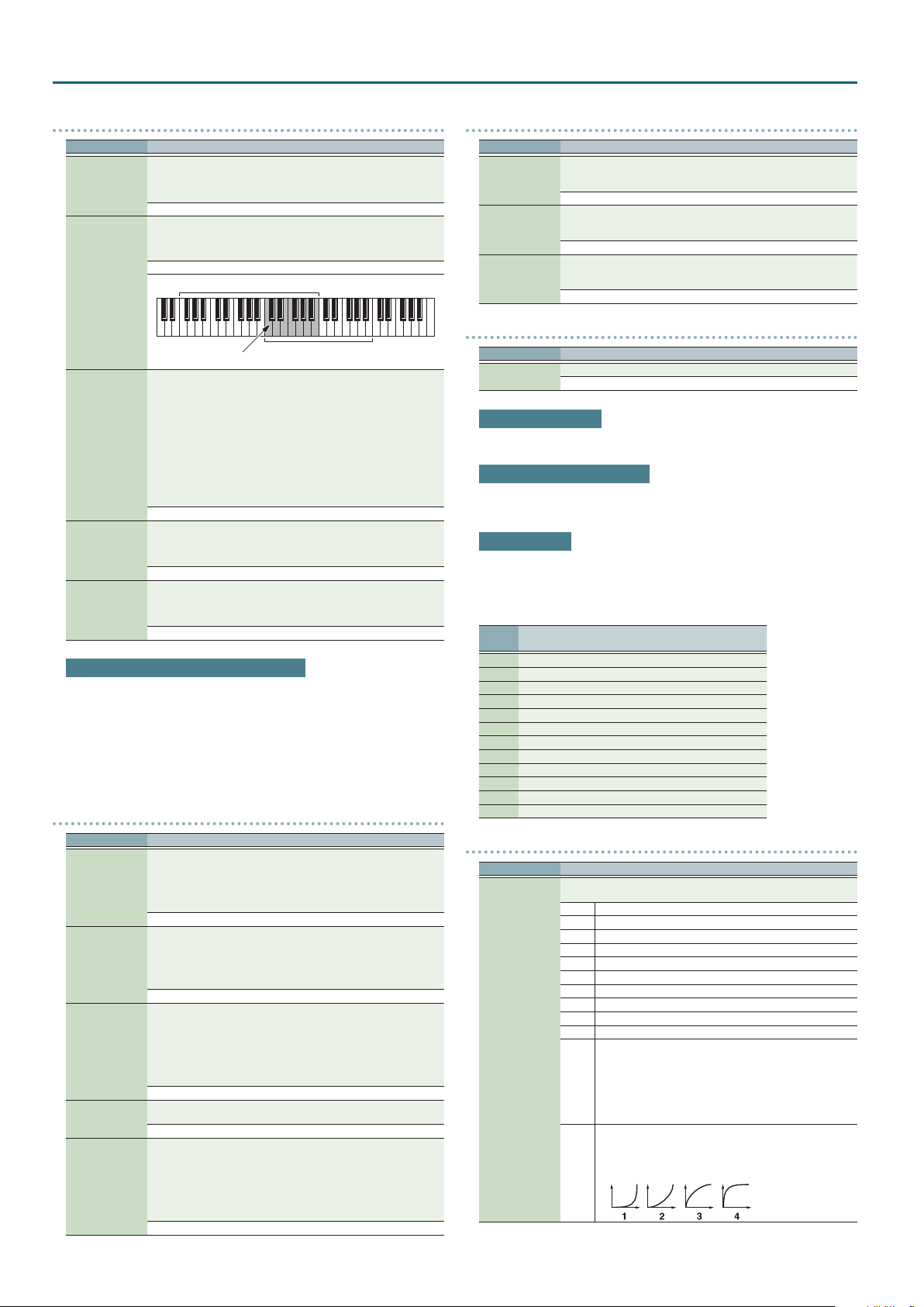
Performance Mode
KBD
Parameter Value/Explanation
Species, for each part, whether or not the keyboard controller section will
be connected to the internal sound generator and MIDI OUT.
Kbd
RngLo, RngUp
V-Sens
(Velocity
Sensitivity Oset)
V-Rsv
Oct
Normally you will leave this o; you can turn it on if you want to layer
sounds.
OFF, ON
Species the lowest/highest note that the tone will sound for each part.
* When the Key Range (p. 7) is set for each individual tone in a patch,
sounds are produced in the range where the Key Range of each tone
and the Key Range for the part overlap.
C- –G9
Key range specied for Performance
The range in which
notes will play
This changes the volume and cuto frequency for each part according to
the velocity with which the keys are pressed. If you want strongly played
notes to raise the volume/cuto frequency, set this parameter to positive
(+) settings. If you want strongly played notes to lower the volume/cuto
frequency, use negative (-) settings. Set Velocity Sensitivity to “0” when you
want sounds played at a xed volume and cuto frequency, regardless of
the force with which the keys are played.
* Patches also contain a Velocity Sensitivity Oset setting (p. 5). The
ultimate Velocity Sensitivity Oset value is the sum of the part’s and the
patch’s Velocity Sensitivity Osets. Accordingly, if the patch’s Velocity
Sensitivity Oset is set to “127” (maximum), there will be no change in
the part’s Velocity Sensitivity Oset, even when this is set to a positive
value.
-63–+63
Species the number of voices that will be reserved for each part when
more than 128 voices are played simultaneously.
* It is not possible for the settings of all parts to total an amount greater
than 128.
0–63, FULL
Adjusts the pitch of the part’s sound up or down in units of an octave (±3
octaves).
* Note that when a drum kit is assigned to a part, you cannot modify the
Octave Shift.
-3–+3
Key range specied for Patch
Calculating the number of voices being used
The JUNO-DS is able to play up to 128 notes simultaneously.
The polyphony, or the number of voices (sounds) does not refer only to the number
of sounds actually being played, but changes according to the number of tones
used in the patches, and the number of Waves used in the tones. The following
method is used to calculate the number of sounds used for one patch being played.
(number of sounds being played) x (number of tones used by patches being played)
x (number of waves used in the tones) Realtime Stretch requires twice the normal
polyphony.
OFFSET
Parameter Value/Explanation
Adjusts the cuto frequency for the patch or drum kit assigned to a part.
* Patches also have a Cuto Oset setting (p. 4). The nal cuto
Cuto
(Cuto Oset)
Reso
(Resonance Oset)
Attack
(Attack Time
Oset)
Decay
Release
(Release Time
Oset)
frequency value is the sum of the tone Cuto Frequency value and the
patch and part Cuto Oset values. If the tone’s cuto frequency is
already set to “127” (maximum), there will be no change produced by
setting the Cuto Oset to a positive value.
-64–+63
Adjusts the Resonance for the patch or rhythm set assigned to a part.
* Patches also have a Resonance Oset setting (p. 4). The nal
Resonance value is the sum of the tone Resonance value and the patch
and part Resonance Oset values. If the tone’s resonance is already set
to “127” (maximum), there will be no change produced by setting the
resonance oset to a positive value.
-64–+63
Adjusts the TVA/TVF Envelope Attack Time for the patch or drum kit
assigned to a part.
* Patches also contain the Attack Time Oset setting (p. 4). The nal
TVA Envelope attack time value is therefore the sum of the tone’s TVA
Envelope Time 1 setting, the patch’s Attack Time Oset, and the part’s
Attack Time Oset. If the tone’s Time 1 is already set to “127” (maximum),
there will be no change produced by setting the Attack Time Oset to a
positive value. The same applies to the TVF envelope.
-64–+63
Adjusts the TVA/TVF Envelope Decay Time for the patch or drum kit
assigned to a part.
-64–+63
Adjusts the TVA/TVF Envelope Release Time for the patch or drum kit
assigned to a part.
* Patches also contain a Release Time Oset setting (p. 4). The nal
TVA Envelope release time value is therefore the sum of the tone’s TVA
Envelope Time 4 setting, the patch’s Release Time Oset, and the part’s
Release Time Oset. If the tone’s Time 4 is set to “127” (maximum), there
will be no change in the Release Time Oset, even when this is set to a
positive value. The same applies to the TVF envelope.
-64–+63
VIBRATO
Parameter Value/Explanation
For each part, adjust the vibrato speed (the rate at which the pitch is
Rate
Depth
Delay
modulated). The pitch will be modulated more rapidly for higher settings,
and more slowly with lower settings.
-64–+63
For each part, this adjusts the depth of the vibrato eect (the depth at
which the pitch is modulated). The pitch will be modulated more greatly
for higher settings, and less with lower settings.
-64–+63
For each part, this adjusts the time delay until the vibrato (pitch
modulation) eect begins. Higher settings will produce a longer delay
time before vibrato begins, while lower settings produce a shorter time.
-64–+63
SCALE
Parameter Value/Explanation
C–B
Make scale tune settings for each part.
-64–+63
Equal Temperament
This tuning divides the octave into 12 equal parts, and is the most widely used
method of temperament used in Western music.
Just Temperament (Tonic of C)
Compared with equal temperament, the principle triads sound pure in this
tuning. However, this eect is achieved only in one key, and the triads will become
ambiguous if you transpose.
Arabian Scale
In this scale, E and B are a quarter note lower and C
higher compared to equal temperament. The intervals between G and B, C and E, F
¾
, B² and C¾, and E² and F¾ have a natural third—the interval between a major
and G
third and a minor third. On the JUNO-DS, you can use Arabian temperament in the
¾
, F¾ and G¾ are a quarter-note
three keys of G, C and F.
Note
name
C 0 0 -6
¾
C
D 0 +4 -2
²
E
E 0 -14 -51
F 0 -2 -8
¾
F
G 0 +2 -4
¾
G
A 0 -16 0
²
B
B 0 -12 -49
Equal
temperament
Just Temperament
(tonic C)
0 -8 +45
0 +16 -12
0 -10 +43
0 +14 +47
0 +14 -10
Arabian Scale
MIDI
Parameter Value/Explanation
For each MIDI channel, specify whether MIDI messages will be received
(ON), or not (OFF). Assigning a check mark (() will enable reception.
PC Program Change
BS Bank Selec t
PB Pitch Bend
PA Polyphonic Aftertouch
CA Channel Aftertouch
MD Modulation
VO Volume
PN Pan
EX Expression
HD Hold 1
PC–VC
Set PL (phase lock) to “(” (ON) when you want to suppress
discrepancies in timing of parts played on the same MIDI channel.
* When the PL (phase lock) is set to “ON,” parts on the same MIDI
channel are put in a condition in which their timing is matched,
PL
enabling them to be played at the same time. Accordingly, a
certain amount of time may elapse between reception of the
Note messages and playing of the sounds. Turn this setting to
“ON” only as needed.
Selects Velocity Curve for each MIDI channel one of the four
following Velocity Curve types that best matches the touch of the
connected MIDI keyboard.
Set this to “–” (OFF) if you are using the MIDI keyboard’s own
VC
velocity curve.
20
Page 21

Part Edit
MEMO
5PART EDIT and PERFORMANCE EDIT have the same parameters in common.
5If you’re using the pattern sequencer, the part edit settings are saved as a “pattern.”
Procedure
Press the [PATCH/PERFORM] button to make it light.
1.
Select a performance that you want to edit.
2.
Press the [SAMPLE IMPORT] button and [DAW CONTROL] button
3.
simultaneously.
The EDIT MENU screen appears.
Move the cursor to “PART EDIT,” and press the [ENTER] button.
4.
The PART EDIT screen appears.
MEMO
5In the PART EDIT screen, you can use pads [1]–[8] to select the part that you
want to edit. If you hold down the [SHIFT] button and press a pad [1]–[8], a part
9–16 is selected.
Performance Parameters
Performance Mode
Move the cursor to tab, and use the [K] [J] buttons to switch the pages.
5.
Move the cursor to the parameter that you want to edit, and use the value
6.
dial to change the value.
To save the edited settings, perform the operation “Saving Your Settings
7.
(Write)” (refer to owner’s manual).
PATC H
Parameter Value/Explanation
Sets the assignment of a patch (Patch) or drum kit (Drum) to each of the
TYPE
BANK
Category number
parts.
Patch, Drum
Selects the group to which the desired patch or drum kit belongs.
DS (DS tone), PRST (Preset), GM (GM2 tone), EXP (expansion sounds), USER
Selects the desired patch or drum kit by its number.
0001–
LEVEL/CH
Parameter Value/Explanation
Turns on the part that you want to solo. Parts other than the soloed part
Solo Switch
Mute Switch
Level
Pan
Rx Switch
Rx Channel
are not heard.
OFF, ON
Species whether each part’s performance is temporarily muted (ON) or
not muted (OFF).
* The Mute parameter does not turn the part o; it mutes the sound by
minimizing the volume. Therefore, the part still receives MIDI messages.
OFF, ON
Adjust the volume of each part. This setting’s main purpose is to adjust the
volume balance between parts.
0–127
Adjust the pan of each part. “L64” is far left, “0” is center, and “63R” is far
right.
L64–0–63R
For each part, specify whether MIDI messages will be received (ON), or not
(OFF).
If this is “OFF,” the part will not respond. Normally, you should leave this
“ON,” but you can turn it “OFF” when you do not want a specic part to be
playing during song playback.
OFF, ON
Species the MIDI receive channel for each part.
* You can’t edit this parameter if the [PATTERN SEQUENCER] button is lit.
1–16
OUTPUT
Parameter Value/Explanation
Species for each part how the direct sound will be output.
MFX
Output Assign
Output MFX Sel
Output Level
Cho Send Level
Rev Send level
L+R
L, R
PAT Outputs according to the settings for patch.
Of the three types of MFX that can be used simultaneously, specify which
MFX will be used.
1–3 (MFX1–MFX3)
Set the level of the signal that is sent to the output destination specied
by Part Output Assign.
0–127
Sets the level of the signal sent to chorus for each part.
0–127
Sets the level of the signal sent to reverb for each part.
0–127
Output in stereo through MFX. You can also apply chorus or
reverb to the sound that passes through MFX.
Output to the OUTPUT L (MONO) jack and OUTPUT R jack in
stereo without passing through MFX.
Output to the OUTPUT L (MONO) jack or OUTPUT R jack in
mono without passing through MFX.
PITCH
Parameter Value/Explanation
Adjusts the pitch of the part’s sound up or down in units of an octave (±3
Octave Shift
Coarse Tune
Fine Tune
Mono/Poly
Legato Switch
Bend Range
Porta Switch
Porta Time
octaves).
* Note that when a rhythm set is assigned to a part, you cannot modify
the Octave Shift.
-3–+3
Adjusts the pitch of the part’s sound up or down in semitone steps (±4
octaves).
-48–+48
Adjusts the pitch of the part’s sound up or down in 1-cent steps (±50
cents).
-50–+50
Set this parameter to “MONO” when the patch assigned to the part is to
be played monophonically, or to “POLY” when the patch is to be played
polyphonically. If you want to use the Mono/Poly setting of the patch
assigned to the part (p. 5), set this to “PAT.”
* This setting is ignored for parts to which a drum kit is assigned.
MONO, POLY, PAT
Turn this parameter “ON” when you want to use the Legato feature and
“OFF” when you don’t. If you want to use the Legato Switch setting of the
patch assigned to the part (p. 5), set this to “PAT.”
* This setting is ignored for parts to which a drum kit is assigned.
OFF, ON, PAT
Species the amount of pitch change in semitones (2 octaves) that will
occur when the Pitch Bend Lever is moved. The amount of change when
the lever is tilted is set to the same value for both left and right sides. If you
want to use the Pitch Bend Range setting of the patch assigned to the part
(p. 7), set this to “PAT.”
0–24, PAT
Turn this parameter “ON” when you want to apply Portamento and “OFF”
when you don’t. If you want to use the Portamento Switch setting of the
patch assigned to the part (p. 5), set this to “PAT.”
OFF, ON, PAT
When portamento is used, this species the time over which the pitch
will change. Higher settings will cause the pitch change to the next note
to take more time. If you want to use the Portamento Time setting of the
patch assigned to the part (p. 5), set this to “PAT.”
* This setting is ignored for parts to which a drum kit is assigned.
0–127, PAT
21
Page 22
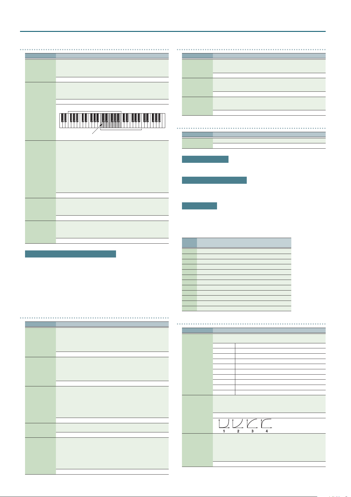
Performance Mode
KBD
Parameter Value/Explanation
Species, for each part, whether or not the keyboard controller section will
be connected to the internal sound generator and MIDI OUT.
Kbd Switch
Key Range Lower,
Upper
Velo Sens Oset
(Velocity
Sensitivity Oset)
Voice Reserve
Octave Shift
Normally you will leave this o; you can turn it on if you want to layer
sounds.
OFF, ON
Species the lowest/highest note that the tone will sound for each part.
* When the Key Range (p. 7) is set for each individual tone in a patch,
sounds are produced in the range where the Key Range of each tone
and the Key Range for the part overlap.
1–16
Key range specied for Performance
The range in which
notes will play
This changes the volume and cuto frequency for each part according to
the velocity with which the keys are pressed. If you want strongly played
notes to raise the volume/cuto frequency, set this parameter to positive
(+) settings. If you want strongly played notes to lower the volume/cuto
frequency, use negative (-) settings. Set Velocity Sensitivity to “0” when you
want sounds played at a xed volume and cuto frequency, regardless of
the force with which the keys are played.
* Patches also contain a Velocity Sensitivity Oset setting (p. 5). The
ultimate Velocity Sensitivity Oset value is the sum of the part’s and the
patch’s Velocity Sensitivity Osets. Accordingly, if the patch’s Velocity
Sensitivity Oset is set to “127” (maximum), there will be no change in
the part’s Velocity Sensitivity Oset, even when this is set to a positive
value.
-63–+63
Species the number of voices that will be reserved for each part when
more than 128 voices are played simultaneously.
* It is not possible for the settings of all parts to total an amount greater
than 128.
0–63, FULL
Adjusts the pitch of the part’s sound up or down in units of an octave (±3
octaves).
* Note that when a rhythm set is assigned to a part, you cannot modify
the Octave Shift.
-3–+3
Key range specied for Patch
Calculating the number of voices being used
The JUNO-DS is able to play up to 128 notes simultaneously.
The polyphony, or the number of voices (sounds) does not refer only to the number
of sounds actually being played, but changes according to the number of tones
used in the patches,
and the number of Waves used in the tones. The following method is used to
calculate the number of sounds used for one patch being played.
(number of sounds being Played) x (number of tones used by patches being played)
x (number of waves used in the tones) Realtime Stretch requires twice the normal
polyphony.
OFFSET
Parameter Value/Explanation
Adjusts the cuto frequency for the patch or rhythm set assigned to a part.
* Patches also have a Cuto Oset setting (p. 4). The nal Cuto
frequency value is the sum of the tone Cuto Frequency value and the
Cuto Oset
Reso Oset
(Resonance Oset)
Attack Oset
(Attack Time
Oset)
Decay Oset
Release Oset
(Release Time
Oset)
patch and part Cuto Oset values. If the tone’s cuto frequency is
already set to “127” (maximum), there will be no change produced by
setting the Cuto Oset to a positive value.
-64–+63
Adjusts the Resonance for the patch or rhythm set assigned to a part.
* Patches also have a Resonance Oset setting (p. 4). The nal
Resonance value is the sum of the tone Resonance value and the patch
and part Resonance Oset values. If the tone’s resonance is already set
to “127” (maximum), there will be no change produced by setting the
resonance oset to a positive value.
-64–+63
Adjusts the TVA/TVF Envelope Attack Time for the patch or drum kit
assigned to a part.
* Patches also contain the Attack Time Oset setting (p. 4). The nal
TVA Envelope attack time value is therefore the sum of the tone’s TVA
Envelope Time 1 setting, the patch’s Attack Time Oset, and the part’s
Attack Time Oset. If the tone’s Time 1 is already set to “127” (maximum),
there will be no change produced by setting the Attack Time Oset to a
positive value. The same applies to the TVF envelope.
-64–+63
Adjusts the TVA/TVF Envelope Decay Time for the patch or drum kit
assigned to a part.
-64–+63
Adjusts the TVA/TVF Envelope Release Time for the patch or drum kit
assigned to a part.
* Patches also contain a Release Time Oset setting (p. 4). The nal
TVA Envelope release time value is therefore the sum of the tone’s TVA
Envelope Time 4 setting, the patch’s Release Time Oset, and the part’s
Release Time Oset. If the tone’s Time 4 is set to “127” (maximum), there
will be no change in the Release Time Oset, even when this is set to a
positive value. The same applies to the TVF envelope.
-64–+63
VIBRATO
Parameter Value/Explanation
For each part, adjust the vibrato speed (the rate at which the pitch is
Vibrato Rate
Vibrato Depth
Vibrato Delay
modulated). The pitch will be modulated more rapidly for higher settings,
and more slowly with lower settings.
-64–+63
For each part, this adjusts the depth of the vibrato eect (the depth at
which the pitch is modulated). The pitch will be modulated more greatly
for higher settings, and less with lower settings.
-64–+63
For each part, this adjusts the time delay until the vibrato (pitch
modulation) eect begins. Higher settings will produce a longer delay
time before vibrato begins, while lower settings produce a shorter time.
-64–+63
SCALE
Parameter Value/Explanation
C–B
Make scale tune settings for each part.
-64–+63
Equal Temperament
This tuning divides the octave into 12 equal parts, and is the most widely used
method of temperament used in Western music.
Just Temperament (Tonic of C)
Compared with equal temperament, the principle triads sound pure in this
tuning. However, this eect is achieved only in one key, and the triads will become
ambiguous if you transpose.
Arabian Scale
In this scale, E and B are a quarter note lower and C
higher compared to equal temperament. The intervals between G and B, C and E, F
¾
, B² and C¾, and E² and F¾ have a natural third—the interval between a major
and G
third and a minor third. On the JUNO-DS, you can use Arabian temperament in the
¾
, F¾ and G¾ are a quarter-note
three keys of G, C and F.
Note
name
C 0 0 -6
¾
C
D 0 +4 -2
²
E
E 0 -14 -51
F 0 -2 -8
¾
F
G 0 +2 -4
¾
G
A 0 -16 0
²
B
B 0 -12 -49
Equal
temperament
Just Temperament
(tonic C)
0 -8 +45
0 +16 -12
0 -10 +43
0 +14 +47
0 +14 -10
Arabian Scale
MIDI
Parameter Value/Explanation
For each MIDI channel, specify whether MIDI messages will be received
(ON), or not (OFF). Assigning a check mark (() will enable reception.
PC Program Change
BS Bank Selec t
BEND Pitch Bend
PC–HOLD
VERO CRV
PHASELOCK
PAFT Polyphonic Aftertouch
CAFT Channel Aftertouch
MOD Modulation
VOL Volume
PAN Pan
EXP Expression
HOLD Hold 1
Selects Velocity Curve for each MIDI channel one of the four following
Velocity Curve types that best matches the touch of the connected MIDI
keyboard.
Set this to “OFF” if you are using the MIDI keyboard’s own velocity curve.
OFF, 1–4
Set PHASELOCK to “ON” when you want to suppress discrepancies in
timing of parts played on the same MIDI channel.
* When the PHASELOCK is set to “ON,” parts on the same MIDI channel
are put in a condition in which their timing is matched, enabling them
to be played at the same time. Accordingly, a certain amount of time
may elapse between reception of the Note messages and playing of the
sounds. Turn this setting to “ON” only as needed.
OFF, ON
22
Page 23
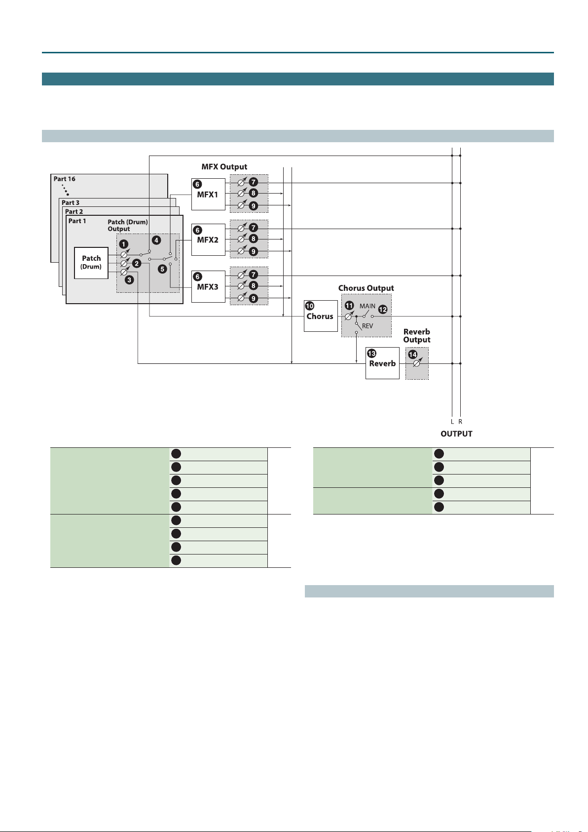
Performance Mode
Eects Edit
In Performance mode you can use three multi eects (MFX1–3), one chorus, and one reverb. For each of the three MFX, the chorus, and the reverb, you can specify whether it
will operate according to the eect settings of the performance, or according to the eect settings of the patch or drum kit assigned to the part you specify.
The three MFX can be used independently, or you can connect two or three of them in series.
Signal Flow
Make these settings in the “OUTPUT” tab of
the PART EDIT screen.
Make these settings in the “MFX1–3” tab of the
EFFECTS EDIT screen.
Output Level
1
Cho Send Level
2
Rev Send Send
3
Output Assign
4
Output MFX Sel
5
MFX Type
6
Output Level
7
Chorus Send Level
8
Reverb Send level
9
p. 21
p. 24
Chorus Type
10
Make these settings in the “CHORUS” tab of
the EFFECTS EDIT screen.
Make these settings in the “REVERB” tab of the
EFFECTS EDIT screen.
11
12
13
14
Chorus Level
Output Select
Reverb Type
Reverb Level
Procedure
Press the [SAMPLE IMPORT] button and [DAW CONTROL] button
1.
simultaneously.
The EDIT MENU screen appears.
Move the cursor to “EFFECTS EDIT,” and press the [ENTER] button.
2.
The EFFECTS EDIT screen appears.
Move the cursor to tab, and use the [K] [J] buttons to switch the pages.
3.
Move the cursor to the parameter that you want to edit, and use the value
4.
dial to change the value.
To save the edited settings, perform the operation “Saving Your Settings
5.
(Write)” (refer to owner’s manual).
p. 24
23
Page 24
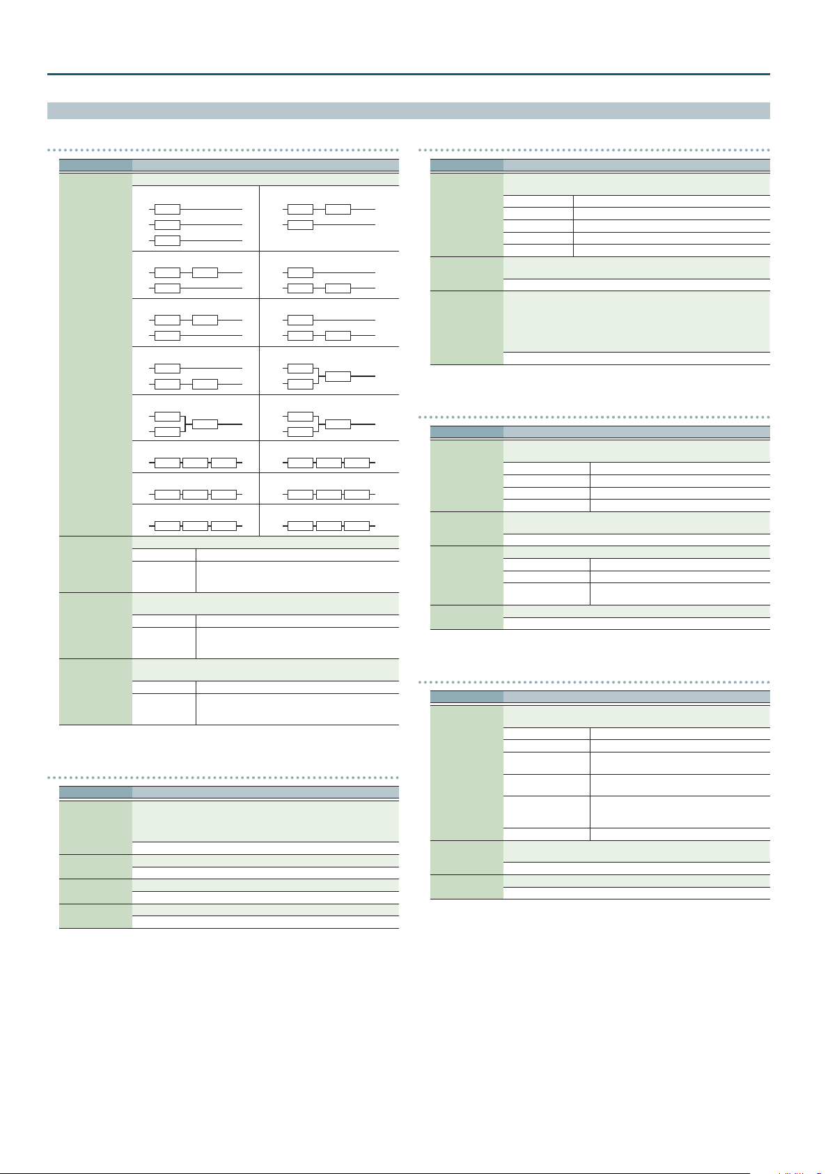
Performance Mode
Eects Parameters
COMMON
Parameter Value/Explanation
Specify how MFX1–3 will be connected.
TYPE01
MFX1
MFX2
MFX3
TYPE03
MFX1
MFX2
TYPE05
MFX2
MFX3
MFX Structure
MFX1–3 Source
Chorus Source
Reverb Source
TYPE07
MFX1
MFX3 MFX2
TYPE09
MFX2
MFX3
TYPE11
MFX1 MFX2 MFX3
TYPE13
MFX2 MFX3 MFX1
TYPE15
MFX3 MFX1 MFX2
Selects the MFX parameter settings that will be used by the performance.
PERFORM Use the MFX settings of the performance
UPPER (PART1),
LOWER (PART2),
PART3–16
Selects the chorus parameter settings that will be used by the
performance.
PERFORM Use the chorus settings of the performance
UPPER (PART1),
LOWER (PART2),
PART3–16
Selects the reverb parameter settings that will be used by the
performance.
PERFORM Use the reverb settings of the performance
UPPER (PART1),
LOWER (PART2),
PART3–16
MFX1–3
Parameter Value/Explanation
Turns MFX on/o, and species the type of MFX that is used. If MFX is on,
shows a “(” mark.
MFX Type
Parameters for
each MFX type
Chorus Send Level
Reverb Send Level
8
* For details on MFX parameters, refer to “MFX Parameters (MFX,
MFX1–3)” (p. 40).
00: THRU–80: BIT CRUSHER
Edit the parameters of the MFX type you’ve selected.
* Refer to “MFX Parameters (MFX, MFX1–3)” (p. 40).
Species the level of the signal sent to the chorus.
0–127
Species the level of the signal sent to the reverb.
0–127
TYPE02
MFX1
MFX2
MFX3
TYPE04
MFX3
MFX1
MFX1
Use the MFX settings of the patch or drum kit assigned
to the specied part
Use the chorus settings of the patch or drum kit
assigned to the specied part
Use the reverb settings of the patch or drum kit
assigned to the specied part
MFX1
MFX2 MFX3
TYPE06
MFX2
MFX3 MFX1
TYPE08
MFX1
MFX2
TYPE10
MFX1
MFX3
TYPE12
MFX1 MFX3 MFX2
TYPE14
MFX2 MFX1 MFX3
TYPE16
MFX3 MFX2 MFX1
MFX3
MFX2
MFX1–3 CTRL
Parameter Value/Explanation
Sets the MIDI message used to change the MFX parameter with the MFX
control.
OFF MFX control will not be used.
Source 1–4
Destination 1–4
Sens 1–4
CC01–31, 33–95 Controller numbers 1–31, 33–95
PITCH BEND Pitch bend
AFTERTOUCH After touch
SYS CTRL1–4 Use the System Control 1–4 Source setting (p. 34).
Sets the MFX parameters to be controlled with the Source1–4. The MFX
parameters available for control will depend on the MFX Type.
* Refer to “MFX Parameters (MFX, MFX1–3)” (p. 40).
Species the depth of MFX control.
Specify a positive (+) value if you want to change the value of the assigned
destination in a positive direction (larger, toward the right, faster, etc.), or
specify a negative value (-) if you want to change the value in a negative
direction (smaller, toward the left, slower, etc.).
Larger values will allow a greater amount of control.
-63–+63
CHORUS
Parameter Value/Explanation
Turns Chorus on/o, and species the type of chorus that is used. If Chorus
is on,
8
Chorus Type
Parameters for
each chorus type
Output Select
Chorus Level
00: OFF Neither chorus or delay is used.
01: CHORUS Chorus is used.
02: DELAY Delay is used.
03: GM2 CHORUS GM2 chorus
Set the parameters of the selected chorus type. The chorus parameters
available for control will depend on the Chorus Type.
* Refer to “Chorus Parameters” (p. 58).
Species how the sound routed through chorus will be output.
MAIN Output to the OUTPUT jacks in stereo.
REV Output to reverb in mono.
M+R
Adjusts the volume of the sound that has passed through chorus.
0–127
REVERB
Parameter Value/Explanation
Turns Reverb on/o, and species the type of reverb that is used. If Reverb
is on,
8
00: OFF Reverb is not used.
01: REVERB Normal reverb
Reverb Type
Parameters for
each reverb type
Reverb Level
02: SRV ROOM
03: SRV HALL
04: SRV PLATE
05: GM2 REVERB GM2 reverb
Set the parameters of the selected reverb type. The reverb parameters
available for control will depend on the Reverb Type.
* Refer to “Reverb Parameters” (p. 58).
Adjusts the volume of the sound that has passed through reverb.
0–127
shows a “(” mark.
shows a “(” mark.
Output to the OUTPUT jacks in stereo, and to
reverb in mono.
This reverb simulates typical room acoustic
reections.
This reverb simulates typical concert hall acoustic
reections.
This reverb simulates a reverb plate, a popular
type of articial reverb unit that derives its sound
from the vibration of a metallic plate.
24
Page 25
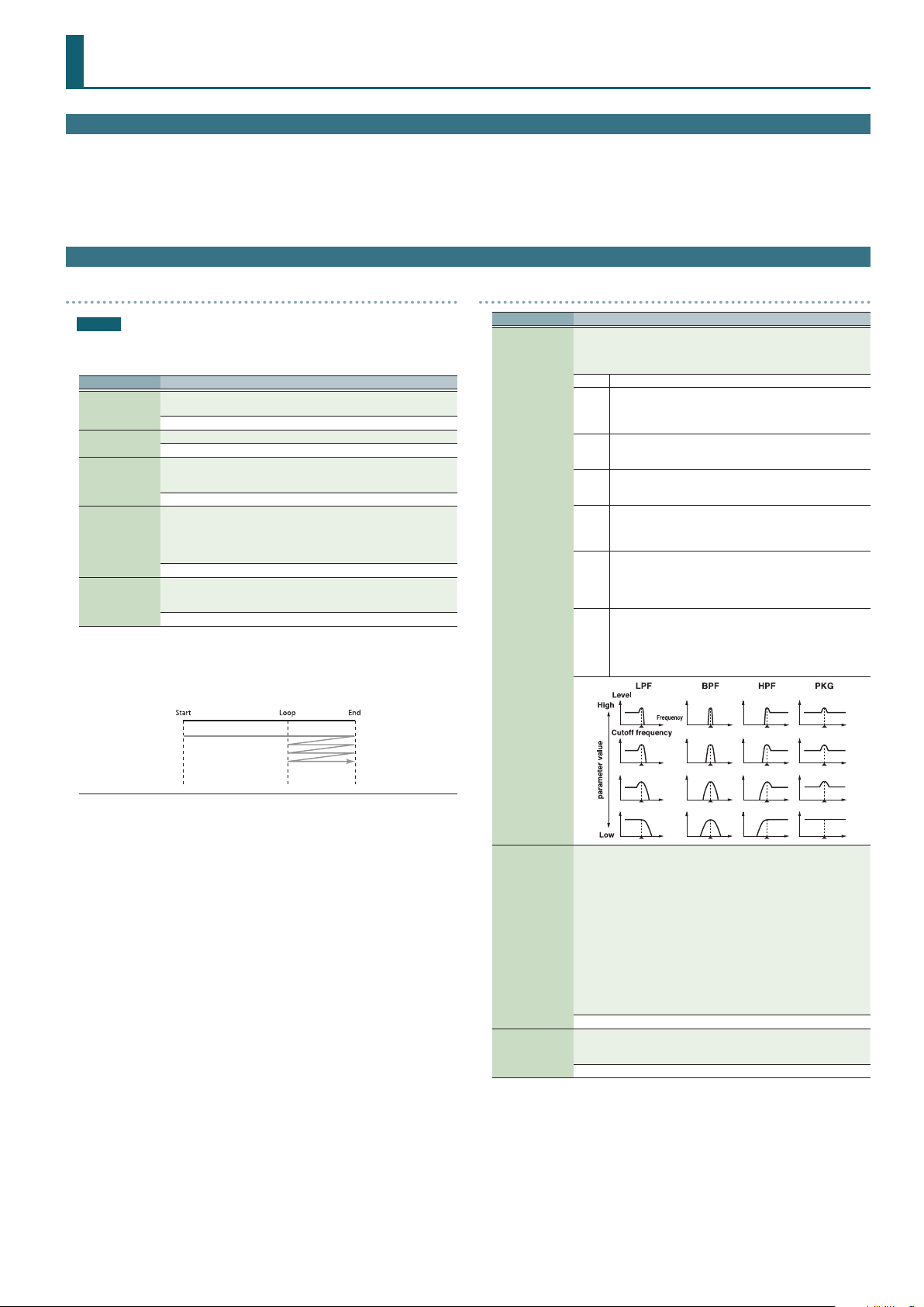
Sample Edit
Procedure
Press the [SAMPLE IMPORT] button.
1.
The SAMPLE MENU screen appears.
Move the cursor to “SAMPLE EDIT” and press the [ENTER] button.
2.
The SAMPLE EDIT screen appears.
Move the cursor to tab, and use the [K] [J] buttons to switch the pages.
3.
Sample Parameters
SAMPLE
NOTE
The following parameters cannot be edited for samples Sp:001–006 in the PRST
bank.
Parameter Value/Explanation
Species the note number that plays the sample at the pitch at which it
Original Key
Loop Switch
Start
Loop
End
(*1)
The length of the imported sample is calculated, and the position of each point is shown as a
time (units: milliseconds).
The displayed value (time) is the value when the sample is played at the key specied by
Original Key. The playback time is shorter than displayed if you play a key that is higher than the
Original Key, and longer than displayed if you play a key that is lower.
was imported.
C-1–G9
Turns loop playback on/o.
OFF, ON
Playback start point (Start Point) (*1)
This lets you skip an unwanted portion of the waveform at the beginning
of the sample so that the sample plays with the desired timing.
0–
Point at which the repeated portion starts on the second and subsequent
plays (Loop Point) (*1)
Specify this if you want to loop from a location other than Start After the
Sample played back from Start to End, it will then be repeatedly played
back in the forward direction, from the Loop to End.
0–
Playback end point (End Point) (*1)
This lets you omit an unwanted portion of the waveform at the end of the
sample.
0–
Move the cursor to the parameter that you want to edit, and use the value
4.
dial to change the value.
To save the edited settings, perform the operation “Saving Your Settings
5.
(Write)” (refer to owner’s manual).
TVF
Parameter Value/Explanation
Selects the type of lter. A lter cuts or boosts a specic frequency region
to change a sound’s brightness, thickness, or other qualities.
* If you set “LPF2” or “LPF3,” the setting for the Resonance will be ignored
(p. 25).
OFF No lter is used.
Low Pass Filter. This reduces the volume of all frequencies above
the cuto frequency (Cuto Freq) in order to round o, or un-
LPF
brighten the sound.
This is the most common lter used in synthesizers.
Band Pass Filter. This leaves only the frequencies in the region of
BPF
the cuto frequency (Cuto Freq), and cuts the rest. This can be
useful when creating distinctive sounds.
High Pass Filter. This cuts the frequencies in the region below
HPF
the cuto frequency (Cuto Freq). This is suitable for creating
percussive sounds emphasizing their higher tones.
Peaking Filter. This emphasizes the frequencies in the region of
the cuto frequency (Cuto Freq). You can use this to create wah-
PKG
wah eects by employing an LFO to change the cuto frequency
cyclically.
Low Pass Filter 2. Although frequency components above the
Cuto frequency (Cuto Freq) are cut, the sensitivity of this lter
LPF2
Filter Type
is half that of the LPF. This makes it a comparatively warmer low
pass lter. This lter is good for use with simulated instrument
sounds such as the acoustic piano.
Low Pass Filter 3. Although frequency components above the
Cuto frequency (Cuto Freq) are cut, the sensitivity of this lter
changes according to the Cuto frequency. While this lter is
LPF3
also good for use with simulated acoustic instrument sounds,
the nuance it exhibits diers from that of the LPF2, even with the
same TVF Envelope settings.
Cuto Frequency
Resonance
Selects the frequency at which the lter begins to have an eect on the
waveform’s frequency components.
“LPF/LPF2/LPF3” selected for the Filter Type
Lower cuto frequency settings reduce a tone’s upper harmonics for a
more rounded, warmer sound. Higher settings make it sound brighter.
“BPF” selected for the Filter Type
Harmonic components will change depending on the TVF Cuto
Frequency setting. This can be useful when creating distinctive sounds.
“HPF” selected for the Filter Type
Higher Cuto Frequency settings will reduce lower harmonics to
emphasize just the brighter components of the sound.
“PKG” selected for the Filter Type
The harmonics to be emphasized will vary depending on Cuto Frequency
setting.
0–127
Emphasizes the portion of the sound in the region of the cuto frequency,
adding character to the sound. Excessively high settings can produce
oscillation, causing the sound to distort.
0–127
25
Page 26
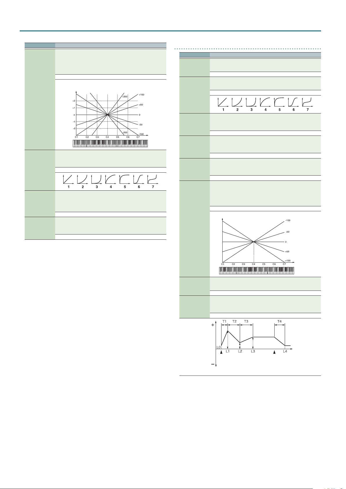
Sample Edit
Parameter Value/Explanation
Use this parameter if you want the cuto frequency to change according
to the key that is pressed. Relative to the cuto frequency at the C4 key
(center C), positive (+) settings will cause the cuto frequency to rise
for notes higher than C4, and negative (-) settings will cause the cuto
frequency to fall for notes higher than C4.
Larger settings will produce greater change.
-200–+200
Cuto frequency
(Octave)
Cuto Keyfollow
Selects one of the following seven curves that determine how keyboard
playing dynamics (velocity) inuence the cuto frequency.
Set this to “FIXED” if you don’t want the Cuto frequency to be aected by
the keyboard velocity.
Cuto V-Curve
Cuto V-Sens
Resonance V-Sens
FIXED, 1–7
Use this parameter when changing the cuto frequency to be applied as a
result of changes in playing velocity. If you want strongly played notes to
raise the cuto frequency, set this parameter to positive (+) settings. If you
want strongly played notes to lower the cuto frequency, use negative (-)
settings.
-63–+63
This allows keyboard velocity to modify the amount of Resonance. If you
want strongly played notes to have a greater Resonance eect, set this
parameter to positive (+) settings. If you want strongly played notes to
have less Resonance, use negative (-) settings.
-63–+63
Key
TVF ENV
Parameter Value/Explanation
Species the depth of the TVF envelope. Higher settings will cause the TVF
TVF Env Depth
TVF Env V-Curve
TVF Env V-Sens
TVF Env T1 V-Sens
TVF Env T4 V-Sens
TVF Env Time
Keyfollow
envelope to produce greater change. Negative (-) settings will invert the
shape of the envelope.
-63–+63
Selects one of the following 7 curves that will determine how keyboard
playing dynamics will aect the TVF envelope. Set this to “FIXED” if you
don’t want the TVF Envelope to be aected by the keyboard velocity.
FIXED, 1–7
Species how keyboard playing dynamics will aect the depth of the
TVF envelope. Positive (+) settings will cause the TVF envelope to have a
greater eect for strongly played notes, and negative (-) settings will cause
the eect to be less.
-63–+63
This allows keyboard dynamics to aect the Time 1 of the TVF envelope.
If you want Time 1 to be speeded up for strongly played notes, set this
parameter to a positive (+) value. If you want it to be slowed down, set this
to a negative (-) value.
-63–+63
The parameter to use when you want key release speed to control the
Time 4 value of the TVF envelope. If you want Time 4 to be speeded up
for quickly released notes, set this parameter to a positive (+) value. If you
want it to be slowed down, set this to a negative (-) value.
-63–+63
Use this setting if you want the TVF envelope times (Time 2–Time 4) to be
aected by the keyboard location. Based on the TVF envelope times for
the C4 key (center C), positive (+) settings will cause notes higher than
C4 to have increasingly shorter times, and negative (-) settings will cause
them to have increasingly longer times. Larger settings will produce
greater change.
-100–+100
Time
TVF Env Time 1–4
TVF Env Level 0–4
Frequency
Key
Specify the TVF envelope times (Time 1–Time 4). Higher settings will
lengthen the time until the next cuto frequency level is reached. (For
example, Time 2 is the time over which Level 1 will change to Level 2.)
0–127
Specify the TVF envelope levels (Level 0–Level 4). These settings specify
how the cuto frequency will change at each point, relative to the
standard cuto frequency (the cuto frequency value specied in the TVF
screen).
0–127
Cuto
Time
Note on
T: Time L: Level
Note o
26
Page 27
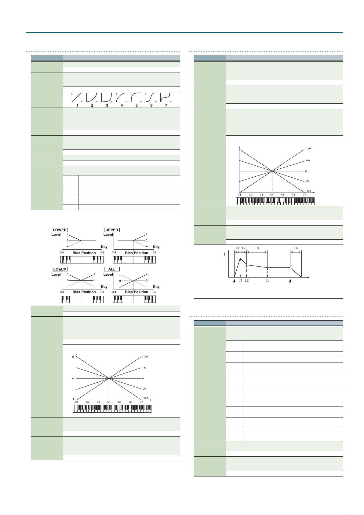
Sample Edit
TVA
Parameter Value/Explanation
Tone Level
Level V-Curve
Level V-Sens
Bias Level
Bias Position
Bias Direction
Bias
Bias causes the volume to be aected by the keyboard position. This is useful for changing
volume through keyboard position (pitch) when playing acoustic instruments.
Sets the volume of the tone.
0–127
You can select from seven curves that determine how keyboard playing
strength will aect the volume. If you do not want the volume of the tone
to be aected by the force with which you play the key, set this to “FIXED.”
FIXED, 1–7
Set this when you want the volume of the tone to change depending on
the force with which you press the keys. Set this to a positive (+) value to
have the changes in tone volume increase the more forcefully the keys are
played; to make the tone play more softly as you play harder, set this to a
negative (-) value.
-63–+63
Adjusts the angle of the volume change that will occur in the selected Bias
Direction. Larger settings will produce greater change. Negative (-) values
will invert the change direction.
-100–+100
Species the key relative to which the volume will be modied.
C-1–G9
Selects the direction in which change will occur starting from the Bias
Position.
The volume will be modied for the keyboard area below the
LWR
Bias Position.
The volume will be modied for the keyboard area above the
UPR
Bias Position.
The volume will be modied symmetrically toward the left and
L&U
right of the Bias Position.
ALL The volume changes linearly with the Bias Position at the center.
TVA ENV
Parameter Value/Explanation
This allows keyboard dynamics to aect the Time 1 of the TVA envelope.
If you want Time 1 to be speeded up for strongly played notes, set this
TVA-Env T1 V-Sens
TVA-Env T4 V-Sens
TVA-Env Time KF
TVA-Env Time 1–4
TVA-Env Level 1–3
parameter to a positive (+) value. If you want it to be slowed down, set this
to a negative (-) value.
-63–+63
The parameter to use when you want key release speed to control the
Time 4 value of the TVA envelope. If you want Time 4 to be speeded up
for quickly released notes, set this parameter to a positive (+) value. If you
want it to be slowed down, set this to a negative (-) value.
-63–+63
Use this setting if you want the TVA envelope times (Time 2–Time 4) to
be aected by the keyboard location. Based on the TVA envelope times
for the C4 key (center C), positive (+) settings will cause notes higher
than C4 to have increasingly shorter times, and negative (-) settings will
cause them to have increasingly longer times. Larger settings will produce
greater change.
-100–+100
Time
Specify the TVA envelope times (Time 1–Time 4). Higher settings will
lengthen the time until the next volume level is reached. (For example,
Time 2 is the time over which Level 1 will change to Level 2.)
0–127
Specify the TVA envelope levels (Level 1–Level 3). These settings specify
how the volume will change at each point, relative to the standard volume
(the Tone Level value specied in the TVA screen).
0–127
Key
Tone Pan
Pan Keyfollow
Random Pan
Depth
Alternate Pan
Depth
Sets the pan of the tone. “L64” is far left, “0” is center, and “63R” is far right.
L64–0–63R
Use this parameter if you want key position to aect panning.
Positive (+) settings will cause notes higher than C4 key (center C) to be
panned increasingly further toward the right, and negative (-) settings will
cause notes higher than C4 key (center C) to be panned toward the left.
Larger settings will produce greater change.
-100–+100
Pan
Key
Use this parameter when you want the stereo location to change randomly
each time you press a key. Higher settings will produce a greater amount
of change.
0–63
This setting causes panning to be alternated between left and right each
time a key is pressed. Higher settings will produce a greater amount
of change. “L” or “R” settings will reverse the order in which the pan will
alternate between left and right.
L63–0–63R
Level
Note on
T: Time L: Level
LFO1
Parameter Value/Explanation
Selects the waveform of the LFO.
* If you set this to “BD-U” or “BD-D,” you must turn the Key Trigger
parameter to “ON.” If this is “OFF,” it will have no eect.
SIN Sine wave
TRI Triangle wave
SAWU Sawtooth wave
SAWD Sawtooth wave (negative polarity)
SQR Square wave
RND Random wave
Waveform
Rate
Rate Detune
BD-U
BD-D
TRP Trapezoidal wave
S&H Sample & Hold wave (one time per cycle, LFO value is changed)
CHS Chaos wave
VSIN
STEP
Adjusts the modulation rate, or speed, of the LFO.
* This setting will be ignored if the Waveform is set to “CHS.”
0–127, note
LFO Rate Detune makes subtle changes in the LFO cycle rate (Rate) each
time a key is pressed. Higher settings will cause greater change.
* This parameter is invalid when Rate is set to “note.”
0–127
Time
Note o
Once the attack of the waveform output by the LFO is allowed
to develop in standard fashion, the waveform then continues
without further change.
Once the decay of the waveform output by the LFO is allowed
to develop in standard fashion, the waveform then continues
without further change.
Modied sine wave. The amplitude of a sine wave is randomly
varied once each cycle.
A waveform generated by the data specied by LFO Step 1–16.
This produces stepped change with a xed pattern similar to a
step modulator.
27
Page 28

Sample Edit
Parameter Value/Explanation
Raises or lowers the LFO waveform relative to the central value (pitch or
cuto frequency). Positive (+) settings will move the waveform so that
Oset
Delay Time
Delay Time KF
Fade Mode
Fade Time
Key Trigger
Pitch Depth
TVF Depth
TVA Depth
Pan Depth
modulation will occur from the central value upward. Negative (-) settings
will move the waveform so that modulation will occur from the central
value downward.
-100, -50, 0, +50, +100
Delay Time (LFO Delay Time) species the time elapsed before the LFO
eect is applied (the eect continues) after the key is pressed (or released).
* After referring to “How to Apply the LFO” (p. 28), change the setting
until the desired eect is achieved.
0–127
Adjusts the value for the Delay Time depending on the key position,
relative to the C4 key (center C). To decrease the time that elapses before
the LFO eect is applied (the eect is continuous) with each higher key
that is pressed in the upper registers, select a positive value; to increase
the elapsed time, select a negative value.
Larger settings will produce greater change. If you do not want the
elapsed time before the LFO eect is applied (the eect is continuous) to
change according to the key pressed, set this to “0.”
-100–+100
Time
Species how the LFO will be applied.
* After referring to “How to Apply the LFO” (p. 28), change the setting
until the desired eect is achieved.
ON <, ON >, OFF <, OFF >
Species the time over which the LFO amplitude will reach the maximum
(minimum).
* After referring to “How to Apply the LFO” (p. 28), change the setting
until the desired eect is achieved.
0–127
Species whether the LFO cycle will be synchronized to begin when the
key is pressed (ON) or not (OFF).
OFF, ON
Species how deeply the LFO will aect pitch.
-63–+63
Species how deeply the LFO will aect the cuto frequency.
-63–+63
Species how deeply the LFO will aect the volume.
-63–+63
Species how deeply the LFO will aect the pan.
-63–+63
STEP LFO
Parameter Value/Explanation
When generating an LFO waveform from the data specied in LFO
Step Type
LFO Step 1–16
Step1–16, specify whether the level will change abruptly at each step
(TYPE 1) or will be connected linearly ( TYPE 2).
TYPE 1, TYPE 2
Species the data for the Step LFO. If the LFO Pitch Depth is +63, each +1
unit of the step data corresponds to a pitch of +50 cents.
-36–+36
Key
How to Apply the LFO
Apply the LFO gradually after the key is pressed
Parameter Value/Explanation
Fade Mode ON <
Delay Time
Fade Time
Apply the LFO immediately when the key is pressed, and then gradually begin to
decrease the eect
Parameter Value/Explanation
Fade Mode ON >
Delay Time The time that the LFO will continue after the keyboard is played.
Fade Time
Apply the LFO gradually after the key is released
Parameter Value/Explanation
Fade Mode OFF <
Delay Time
Fade Time
Apply the LFO from when the key is pressed until it is released, and gradually begin
to decrease the eect when the key is released
Parameter Value/Explanation
Fade Mode OFF >
Delay Time The time that the LFO will continue after the keyboard is released.
Fade Time
The time from when the keyboard is played until the LFO begins to be
applied.
The time over which the LFO amplitude will reach the maximum after the
Delay Time has elapsed.
The time over which the LFO amplitude will reach the minimum after the
Delay Time has elapsed.
The time from when the keyboard is released until the LFO begins to be
applied.
The time over which the LFO amplitude will reach the maximum after the
Delay Time has elapsed.
The time over which the LFO amplitude will reach the minimum after the
Delay Time has elapsed.
28
OUTPUT
Parameter Value/Explanation
Tone Chorus Send
Tone Reverb Send
Species the level of the signal sent to the chorus.
0–127
Species the level of the signal sent to the reverb.
0–127
Page 29

Editing Arpeggios
Press the [ARPEGGIO] button to make it light.
1.
The ARPEGGIO screen appears.
Move the cursor to the item that you want to edit, and use the value dial to edit the setting.
2.
Press the [EXIT] button to exit the ARPEGGIO screen.
3.
Parameter Value/Explanation
STYLE
Part
Arp Hold
Grid
Duration
Motif Refer to “Selecting Ascending/Descending Variations (Motif)” (p. 29).
Velocity
Oct Range
Accent
Selects the arpeggio’s basic performance style.
001–128
In performance mode, this selects the part (only one part) that will be
played by the arpeggio. If a drum kit is assigned to a part, you can play a
drum kit along with the arpeggios.
* This parameter is not shown if the patch mode is selected or the [SUPER
LAYER] button is on.
Part1 (Upper), Part2 (Lower), Part3–16
You can produce arpeggios even without continuing to press the
keyboard.
OFF, ON
Sets the particular note division and resolution in a “single grid” used in
creating the arpeggio in an Arpeggio Style, and how much of a “shue”
syncopation is to be to applied (none/weak/strong) to it (grid type).
* Grid settings are shared with the rhythm pattern.
1/4 (¸) Quar ter note (one grid section = one beat)
1/8 (˙) Eighth note (two grid sections = one beat)
1/8 (˙) L
1/8 (˙) H
1/12 (¯) Eighth note triplet (three grid sections = one beat)
1/16 (˜) Sixteenth note (four grid sections = one beat)
1/16 (˜) L
1/16 (˜) H
1/24 (´) Sixteenth note triplet (six grid sections = one beat)
This determines whether the sounds are played staccato (short and
clipped), or tenuto (fully drawn out).
30–120%
Full
Species the loudness of the notes that you play.
REAL
1–127
Adds an eect that shifts arpeggios one cycle at a time in octave units
(octave range). You can set the shift range upwards or downwards (up to
three octaves up or down).
-3–+3
Adjust the amount (“spread”) of this dynamic variation.
With a setting of “100,” the arpeggiated notes will have the velocities that
are programmed by the arpeggio style. With a setting of “0,” all arpeggiated
notes will be sounded at a xed velocity.
0–100
Eighth note shue Light (two grid sections = one beat, with a
light shue)
Eighth note shue Heavy (two grid sections = one beat, with
a heavy shue)
Sixteenth note shue Light (four grid sections = one beat,
with a light shue)
Sixteenth note shue Heavy (four grid sections = one beat,
with a heavy shue)
* Duration settings are shared with the rhythm pattern.
For example, when set to “30%,” the length of the note in a
grid (or when a series of grids is connected with ties, the nal
grid) is 30% of the full length of the note set in the grid type.
Even if the linked grid is not connected with a tie, the same
note continues to sound until the point at which the next new
sound is specied.
The velocity will change according to how strongly you strike
the key.
The notes will be sounded with the velocity you specify here,
regardless of how strongly you strike the key.
Selecting Ascending/Descending Variations (Motif)
Selects the method used to play sounds (motif) when you have a greater number of
notes than programmed for the Arpeggio Style.
* When the number of keys played is less than the number of notes in the Style,
the highest-pitched of the pressed keys is played by default.
Value Explanation
Up (L)
Up (L&H)
Up (_)
Down (L)
Down (L&H)
Down (_)
U/D (L)
U/D (L&H)
U/D (_)
Rand (L)
Rand (_)
Phrase
Only the lowest of the keys pressed is sounded each time, and the notes play in
order from the lowest of the pressed keys.
Notes from both the lowest and highest pressed keys are sounded each time,
and the notes play in order from the lowest of the pressed keys.
The notes play in order from the lowest of the pressed keys.
No note is played every time.
Only the lowest of the keys pressed is sounded each time, and the notes play in
order from the highest of the pressed keys.
Notes from both the lowest and highest pressed keys are sounded each time,
and the notes play in order from the highest of the pressed keys.
The notes play in order from the highest of the pressed keys.
No note is played every time.
Notes will be sounded from the lowest to the highest key you press and then
back down to the lowest key, with only the lowest key sounded each time.
Notes from both the lowest and highest pressed keys are sounded each time,
and the notes play in order from the lowest of the pressed keys and then back
again in the reverse order.
The notes play in order from the lowest of the pressed keys, and then back
again in the reverse order. No note is played every time.
Notes will be sounded randomly for the keys you press, with only the lowest
key sounded each time.
Only the lowest of the keys pressed is sounded each time, the notes you press
will be sounded randomly. No note is played every time.
Pressing just one key will play a phrase based on the pitch of that key. If you
press more than one key, the key you press last will be used.
29
Page 30

Editing the Vocoder/Auto Pitch
Press the [VOCODER/AUTO PITCH] button to make it light.
1.
The VOCODER/AUTO-PITCH screen appears.
Move the cursor to the parameter that you want to edit, and use the value dial to change the value.
2.
To save the edited settings, perform the operation “Saving the Vocoder/Auto Pitch Settings (Write).”
3.
Parameter Value/Explanation
Mode
Bank, Number
Mode: Vocoder
Carrier Selects the sound that will be the basic waveform of the vocoder sound.
Level
Pan
Mic Sens
Envelope
Synth Level
Mic Mix Level
Mic HPF
Mode: Auto-Pitch
Keyboard Part Selects the sound that is played on the keyboard when using Auto-Pitch.
Type
Level
Pan
Scale
Key
Selects the vocoder or auto-pitch.
Vocoder, Auto-Pitch
Selects the vocoder or auto-pitch setting.
PRST 001–010 Vocoder settings
PRST 011–020 Auto-pitch settings
USER 501–520 User settings
Adjusts the output level of the sound that passes through the vocoder.
0–127
Adjusts the stereo position of the sound that passes through the vocoder.
L64–63R
Species the input sensitivity of the mic.
0–127
Selects the character of the sound.
SHARP Emphasizes the human voice.
SOFT Emphasizes the sound of the instrument.
LONG Produces a vintage sound with a long decay.
Species the input level of the instrumental sound.
0–127
Species the amount of the mic audio passing through the Mic HPF (Mic
High Pass Filter) that is added to the output of the vocoder.
0–127
Species the frequency at which the high pass lter (HPF) applied to the
mic audio starts to take eect. If this is set to “BYPASS,” no lter is applied.
BYPASS, 1000–16000Hz
Selects how Auto-Pitch correction is performed.
SOFT Corrects the pitch smoothly.
HARD Corrects the pitch quickly.
ELECTRIC1 Corrects the pitch in a stepwise manner.
ELECTRIC2
ROBOT Corrects the pitch to the specied note.
Adjusts the output level of the sound that passes through the auto-pitch.
0–127
Adjusts the stereo position of the sound that passes through auto-pitch.
L64–63R
Selects the scale to which Auto-Pitch corrects the pitch.
CHROMATIC Corrects the pitch in semitone steps.
Maj (Min)
If the Scale parameter is set to “Maj (Min),” specify the key of the song
you’re singing. For example if the song is in C major, specify “C”; if the song
is in A minor, specify “Am.”
C–Bm
Relationship between the key of the song and the key signature (and) of
the score
Major keys
Minor keys
Major keys
Corrects the pitch more strongly than ELECTRIC1.
This reproduces the mechanical, step-wise pitch
correction used in pop music.
Corrects the pitch to the notes of the scale (Key)
you specify.
Saving the Vocoder/Auto Pitch Settings (Write)
Press the [WRITE] button to make it light.
1.
The VOCODER/AUTO-PITCH NAME screen appears.
Assign a name to the data that you’re saving.
2.
Operation Explanation
[K] [J] buttons Move the cursor.
Value dial, [–] [+] buttons Select the character.
[I] [H] buttons Switch between uppercase and lowercase.
Inserting/ Deleting Characters
While entering a name, press the [MENU] button.
1.
The NAME MENU window appears. The window closes if you press the button
once again.
Move the cursor to “INSERT” or “DELETE,” and press the [ENTER] button.
2.
Function Explanation
INSERT Press the [ENTER] button to insert a space (blank) at the cursor location.
DELETE
When you’ve specied the name, press the [ENTER] button.
3.
Use the value dial to specify the save-destination.
4.
Press the [ENTER] button.
5.
A conrmation message appears.
If you decide to cancel, press the [EXIT] button.
Move the cursor to “OK,” and press the [ENTER] button.
6.
Saving is complete when the screen indicates “Completed!”
NOTE
Never turn o the power while the screen indicates “Writing....”
Press the [ENTER] button to delete the character at the cursor location;
subsequent characters will be moved forward to ll the gap.
30
Octave
Gender
Balance
Note
Minor keys
Makes the pitch one octave higher/lower.
-1, 0, +1
Settings in the “-” direction give the voice an increasingly masculine
character; settings in the “+” direction give the voice an increasingly
feminine character.
-10–+10
Species the volume balance between the direct sound (D) and the eect
sound (W).
D100:0W–D0:100W
Fixes the pitch.
* Available if Type is set to “Robot.”
C–B
Page 31

Creating an Original Scale (USER SCALE)
You can adjust the pitch of each note from C through B in units of one cent.
The pitch you specify for each note is applied to that note for all octaves.
You can create and save nine dierent “user scales” for later recall.
Setting a User Scale
Press [MENU] button.
1.
The MENU screen appears.
Move the cursor to “USER SCALE,” and press the [ENTER] button.
2.
The USER SCALE screen appears.
Select each of the 12 notes from C to B, and use the value dial to edit their
3.
pitch.
* You can also use the keyboard to select a note to edit.
Value -64–+63
Quarter Tone settings
In the USER SCALE screen, hold down the OCTAVE [DOWN] button and
1.
play a note on the keyboard.
The pitch of the note you played is attened by 1/4 semitone (-50 cents).
Once again hold down the OCTAVE [DOWN] button and play the same note to
restore it to its original pitch.
In the SCALE EDIT screen, hold down the OCTAVE [UP] button and play a note
2.
on the keyboard.
The pitch of the note you played is sharpened by 1/4 semitone (+50 cents).
Once again hold down the OCTAVE [UP] button and play the same note to
restore it to its original pitch.
Recalling a User Scale
Press [MENU] button.
1.
The MENU screen appears.
Move the cursor to “USER SCALE,” and press the [ENTER] button.
2.
The USER SCALE screen appears.
The currently selected user scale number is shown.
When the instrument starts up, this always indicates “OFF.”
Press the [1]–[9] button to select a user scale.
3.
To return to the normal state (OFF), press the [0] button.
MEMO
5If a user scale is selected, the user scale does not change even if you switch
patches or performances.
5User scale returns to OFF when you turn o the power.
5If no user scale is registered to the button that you press, equal temperament is
selected.
5If you use the shortcut ([KEY TOUCH]+[TRANSPOSE]) to access the USER SCALE
screen, you can press a [0]–[9] button to select a user scale and immediately
exit the USER SCALE screen. This is convenient when you want to recall a user
scale while performing.
When you’ve nished making settings, press the [WRITE] button.
4.
The USER SCALE WRITE screen appears.
* If you press the [EXIT] button to exit the USER SCALE screen without performing
the Write operation, the unsaved settings revert to their previous state.
Select the write destination number (USER 1–9), and press the [ENTER]
5.
button.
A conrmation message appears.
If you decide to cancel, press the [EXIT] button.
Move the cursor to “OK,” and press the [ENTER] button.
6.
Writing is complete when the screen indicates “User Scale Write Completed.”
31
Page 32

System Settings
Procedure
Press the [MENU] button.
1.
The MENU screen appears.
Move the cursor to “SYSTEM,” and press the [ENTER] button.
2.
Move the cursor to tab, and use the [K] [J] buttons to switch the pages.
3.
Move the cursor to the parameter that you want to edit, and use the value
4.
dial to change the value.
Press the [EXIT] button to exit the screen.
5.
System Parameters
MEMO
The parameters you edit are saved when you press the [WRITE] button in the
SYSTEM screen, or when you exit the SYSTEM screen.
GENERAL
Parameter Value/Explanation
LCD Contrast
LCD Brightness
Auto O
Power Save Time
Illumination
Adjusting the display contrast.
1–20
Adjusting the display brightness.
1–20
Species whether the unit will turn o automatically after a certain time
has elapsed.
If you don’t want the unit to turn o automatically, choose “OFF” setting.
OFF, 30, 240[min]
Amount of idle time that is to pass before the JUNO-DS enters power-save
mode.
When the JUNO-DS enters power-save mode, it will reduce its power
consumption by turning o the display backlight and minimizing button
illumination.
OFF, 1, 3, 5, 10, 15, 20, 30, 60[min]
Species whether the buttons illuminate when they are waiting for an
operation.
OFF, ON
PAD COLOR
Parameter Value/Explanation
Pad Brightness
COLOR The illumination color of pads [1]–[8] can be specied for each function.
Back Ground
Level Meter
Part Select
Track Select
Track Data
Track Mute
Rhythm Pattern
Audio Player
Tone Switch
Tone Select
Adjusts the brightness of pads [1]–[8].
1–127
OFF, 1–13
1–13
Species the basic illumination color of the pads.
Species the illumination color of the level meter that
indicates the volume when you play the keyboard.
Species the pad illumination color that indicates the
selected part when you use the pads to select a part.
Species the pad illumination color that indicates
the selected track when you use the pads to select a
track.
Species the pad illumination color that indicates a
track already containing performance data.
Species the pad illumination color that indicates a
muted track.
Species the pad illumination color when the
RHYTHM PATTERN screen is displayed.
Species the pad illumination color when the AUDIO
PLAYER screen is displayed.
Species the pad illumination color for pads [5]–
[8] that indicate tones turned on in the PATCH EDIT
screen.
Species the pad illumination color for the pad that
indicates the selected tone in the PATCH EDIT screen.
SOUND
Parameter Value/Explanation
Adjusts the overall tuning of the JUNO-DS.
Master Tune
Master Key Shift
Master Level
Output Gain
Audio Level
The display shows the frequency of the A4 note (center A).
415.3–466.2[Hz]
Shifts the JUNO-DS’s overall pitch range in semitone steps.
-24–+24
Sets the JUNO-DS’s overall volume.
0–127
Adjusts the output gain from the JUNO-DS’s output.
-12–+12[dB]
Species the volume when playing audio le from the Audio Player.
0–127
MASTER EQ
Parameter Value/Explanation
Turn the master EQ (this is an equalizer that is applied to the overall sound
Master EQ Switch
EQ Low Freq
EQ Low Gain
EQ Mid Freq
EQ Mid Gain
EQ Mid Q
EQ High Freq
EQ High Gain
EQ Total Gain
of the entire JUNO-DS) on/o.
OFF, ON
Frequency of the low range.
200, 400[Hz]
Gain of the low frequency range.
-15–+15[dB]
Frequency of the middle range.
200–8000[Hz]
Gain of the middle frequency range.
-15–+15[dB]
Width of the middle frequency range.
Set a higher value for Q to narrow the range to be aected.
0.5, 1.0, 2.0, 4.0, 8.0
Frequency of the high range.
2000, 4000, 8000[Hz]
Gain of the high frequency range.
-15–+15[dB]
Gain of the overall Master EQ.
-15–+15[dB]
KEY TOUCH
Parameter Value/Explanation
Velo Curve
Curve Oset
Velocity
Sets the keyboard’s touch.
LIGHT, MEDIUM, HEAVY
Adjusts the Velo Curve.
Lower values make the keyboard feel lighter.
Higher values make the keyboard feel heavier.
-10–+9
Species the velocity transmitted when a key is played.
REAL
1–127
32
The transmitted velocity value will correspond to the
force with which you strike the key.
The transmitted velocity value will be xed,
regardless of the force with which you strike the key.
Page 33

System Settings
MIC IN SETTINGS
Parameter Value/Explanation
Mic In Level
Mic In Reverb
Switch
Mic In Reverb
Level
Mic In Reverb Type
Mic In Reverb
Time
Noise Suppressor
Switch
Noise Suppressor
Threshold
Noise Suppressor
Release
Mic Mode
Adjusts the input level of the MIC INPUT jack.
0–127
Species whether reverb is applied (ON) to the mic input or not applied
(OFF).
OFF, ON
Adjust the amount of reverb that is applied to the sound of the
microphone.
0–127
Select the type of reverb/delay that is applied to the sound of the
microphone.
ROOM1, ROOM2, STAGE1, STAGE2, HALL1, HALL2, DELAY, PAN-DELAY
Adjusts the length of the reverberation (when Reverb Type is ROOM1–
HALL2) or the delay time of the delay (when Reverb Type is DELAY or PANDELAY).
0–127
Switches the noise suppressor on/o. The noise suppressor is a function
that suppresses noise during periods of silence.
OFF, ON
Adjusts the volume at which noise suppression starts to be applied.
0–127
Adjusts the time from when noise suppression starts until the volume
reaches 0.
0–127
Species the mic input mode.
ALL Sound is input from the mic at all times.
VOCAL FX
PEDAL
Parameter Value/Explanation
Control Pedal
Control Pedal
Assign
Control Pedal
Polarity
Hold Pedal
Continuous Hold
Pedal
Hold Pedal
Polarity
Species the function of the pedal that is connected to the PEDAL
CONTROL jack. The number in parentheses (
of the control change message produced by the pedal when the
corresponding function is assigned.
MODULATION (CC01) Vibrato
PORTA-TIME (CC05) Portamento time
VOLUME (CC07) Level
PAN (CC10) Pan
EXPRESSION (CC11) Level
HOLD
PORTAMENTO (CC65) Portamento switch
SOSTENUTO
RESONANCE (CC71) Resonance
RELEAS-TIME (CC72) Release time
ATTACK-TIME (CC73) Attack time
CUTOFF (CC74) Cuto
DECAY-TIME (CC75) Decay time
VIB-RATE (CC76) Vibrato speed
VIB-DEPTH (CC77) Vibrato depth
VIB-DELAY (CC78) Vibrato delay time
CHORUS-SEND (CC93) The amount of the chorus
REVERB-SEND (CC91) The amount of the reverb
AFTERTOUCH Channel aftertouch
* In Patch mode, the eect of the above functions applies to the currently
selected sound. In Performance mode, the eect applies to the current
part or to parts whose keyboard switch (p. 19, p. 20, p. 22) is on.
START/STOP
TAP-TEMPO
PROG-UP
PROG-DOWN
FAV-UP The favorite of the next number or bank will be selected.
FAV-DOWN
Selects the polarity of the pedal connected to the PEDAL CONTROL jack.
STANDARD, REVERSE
If this is ON, the PEDAL HOLD jack will support half-pedaling.
OFF, ON
Selects the polarity of the pedal connected to the PEDAL HOLD jack.
STANDARD, REVERSE
Sound is input from the mic only when the
[VOCODER/ AUTO PITCH] button is lit, or when the
eect type is set to “79: Di VOCODER” (p. 57).
) is the controller number
(CC64) The sound will be sustained for keys that are
played or were already held down while holding down
the pedal.
(CC66) The sound will be sustained only for keys that
were already pressed when you pressed the pedal.
Pressing the pedal will start/stop the rhythm pattern,
audio player, or pattern sequencer.
The tempo will be set to the interval at which you press
the pedal (Tap Tempo).
If you’re in the patch mode, this selects the next sound.
If you’re in the performance mode, this selects the nextnumbered performance.
If you’re in the patch mode, this selects the previous
sound. If you’re in the performance mode, this selects
the previous-numbered performance.
The favorite of the previous number or bank will be
selected.
KNOB
Parameter Value/Explanation
Species the function that is assigned to each knob when the parameter
controlled by the control knobs is set to ASSIGN 1–4.
OFF No function is assigned.
CC01–31, 32 (OFF),
33–95
Pitch Bend The same eect as moving the pitch bend.
Aftertouch After touch
* In Patch mode, the eect of the above functions applies to the currently
Knob 1–4 Assign
selected sound. In Performance mode, the eect applies to the selected
part.
EQ Low Freq Frequency of the low range.
EQ Low Gain Gain of the low frequency range.
EQ Mid Freq Frequency of the middle range.
EQ Mid Gain Gain of the middle frequency range.
EQ Mid Q Width of the middle frequency range.
EQ High Freq Frequency of the high range.
EQ High Gain Gain of the high frequency range.
SYNC/TEMPO
Parameter Value/Explanation
Species the synchronization message that the JUNO-DS will use for
operation.
Sync Mode
Clock Source
Startup Tempo
Tempo Lock
MASTER
SLAVE
When the Sync Mode is “SLAVE,” this setting species whether the
JUNO-DS will synchronize to synchronization messages from the MIDI IN
connector or from the USB COMPUTER port.
MIDI, USB
Species the tempo when the JUNO-DS starts.
20–250
When you switch performances or patterns, this species whether the
tempo of the newly selected performance/pattern is used, or the current
tempo is maintained.
OFF, ON (maintain)
METRONOME
Parameter Value/Explanation
Species how the metronome will be sounded.
OFF No metronome is sounded.
PLAY-ONLY
Metronome Mode
Metronome Level
Metronome
Sound
Metronome
Accent Switch
REC-ONLY
PLAY&REC
ALW AYS The metronome sounds at all times.
Adjusts the metronome volume.
0–10
Selects the metronome sound.
TYPE1 Conventional metronome sound (rst beat is a bell)
TYPE2 Click sound
TYPE3 Beep sound
TYPE4 Cowbell sound
Adds an accent to the metronome sound.
OFF, ON
Controller number 1–31, 32, 33–95
The JUNO-DS will be the master. Choose this
setting when using the JUNO-DS by itself without
synchronizing to another device.
The JUNO-DS will be the slave. Choose this setting
when you want the JUNO-DS to synchronize to MIDI
Clock messages received from another MIDI device.
The metronome sounds when a pattern is playing.
The metronome sounds when a pattern is being
recorded.
The metronome sounds when a pattern is playing or
being recorded.
33
Page 34

System Settings
MIDI
Parameter Value/Explanation
Determines whether the internal sound generator is disconnected (OFF)
from the controller section (keyboard, pitch bend/modulation lever,
Local Switch
Patch Rx/Tx Ch
Performance
Control Channel
Transmit
Program Change,
Bank Select, Active
Sensing
Transmit
Edit Data
Receive
Program Change,
Bank Select
Soft Through
USB Driver
*1: Download the Driver
In order to use the JUNO-DS with the “VENDOR” setting, you must download the driver
from the following URL and install it on your computer.
For details on installation, refer to the following URL.
&
http://www.roland.com/support/
buttons, sliders, pedal, and so on); or not disconnected (ON). Normally
you’ll leave this “ON.” Choose the “OFF” setting if you want operations on
the JUNO-DS to only control DAW software on your computer.
OFF, ON
In patch mode, species the MIDI message transmit/receive channel for
the keyboard part.
1–16
Species the MIDI receive channel on which MIDI messages (program
change/bank select) from an external MIDI device will be received by the
JUNO-DS to switch performances. Choose “OFF” setting if you don’t want
performances to be switched from a connected MIDI device.
1–16, OFF
Species whether program change messages/bank select messages/active
sensing messages will be transmitted (ON) or not be transmitted (OFF).
OFF, ON
Species whether changes you make in the settings of a patch or
performance will be transmitted as system exclusive messages (ON), or will
not be transmitted (OFF).
OFF, ON
Species whether program change messages/bank select messages will
be received (ON) or not be received (OFF).
OFF, ON
If this is “ON,” incoming MIDI messages from the MIDI IN connector will be
re-transmitted without change from the MIDI OUT connector.
OFF, ON
Sets the USB driver.
* This setting will take eect when you turn the power o, then on again.
GENERIC
VENDOR
Choose this if you want to use the generic USB driver
provided by your computer’s operating system.
Choose this if you want to use a USB driver
downloaded from the Roland website. (*1)
CONTROL
Parameter Value/Explanation
Specify the MIDI messages that will be used as system controls.
System Control settings allow you to specify MIDI messages that will
apply in common to the entire JUNO-DS, and can be used for controlling
volume, tone, etc.
You can assign up to four MIDI messages for this type of control.
Sys Ctrl 1–4
Source
* If you want to make assignments for realtime control of the sound and
eects for each tone independently, use “Matrix control” (p. 12) or
“MFX control” (p. 18).
OFF No function is assigned.
CC01–31, 32 (OFF),
33–95
PITCH BEND The same eect as moving the pitch bend.
AFTERTOUCH Aftertouch
Controller number 1–31, 32, 33–95
INFORMATION
Parameter Value/Explanation
Version View the software version.
Expansion Displays information about expansion sounds.
34
Page 35

Connecting to a Computer via USB
If you use a commercially available USB cable to connect a USB port of your
computer to the USB COMPUTER port located on the rear panel of the JUNO-DS,
you can use MIDI-compatible software (DAW software) to play back audio and MIDI
data on the JUNO-DS.
USB COMPUTER port
For details on operating requirements, refer to the Roland website.
http://www.roland.com/support/
NOTE
5For some types of computer, this might not work correctly. Refer to the Roland
website for details on the operating systems that are supported.
5A USB cable is not included. You can purchase one from the dealer where you
purchased the JUNO-DS.
5Use a USB 2.0 cable.
5Your computer’s USB port must support USB 2.0 Hi-Speed.
5Turn on the power of the JUNO-DS before you start the DAW software on your
computer. Don’t turn the JUNO-DS’s power on/o while your DAW software is
running.
USB audio
Making USB Driver Settings
Here’s how to switch between the JUNO-DS’s dedicated USB driver and the generic
driver provided by your operating system.
Press the [MENU] button.
1.
The MENU screen appears.
Move the cursor to “SYSTEM,” and press the [ENTER] button.
2.
The SYSTEM screen appears.
Move the cursor to “MIDI” tab – “USB Driver,” and use the value dial to select
3.
the driver.
Driver
VENDOR
GENERIC
When you switch the driver, a conrmation screen appears.
If you decide to cancel, press the [EXIT] button.
Move the cursor to “WRITE,” and press the [ENTER] button.
4.
Setting is complete when the screen indicates “Completed.”
MEMO
This system takes eect when the JUNO-DS is powered-on.
Turn the power o, and then on again.
5.
Explanation
The dedicated driver provided by Roland specically for the JUNO-DS is used.
Both MIDI and audio are available.
The generic driver of the operating system is used.
Only MIDI is available.
JUNO-DS 0 Computer
If the JUNO-DS is connected to your computer via a USB cable, the audio output
you’ve chosen in the JUNO-DS can be recorded into your computer’s DAW software.
Computer 0 JUNO-DS
If the JUNO-DS is connected to your computer via a USB cable, the sound of your
computer can be reproduced from an audio system connected to the JUNO-DS’s
jacks.
USB MIDI
If the JUNO-DS is connected to your computer via a USB cable, the JUNO-DS’s
performance data (MIDI data) can be recorded into your DAW software, and
performance data (MIDI data) played back by your DAW software can be sounded
by the JUNO-DS’s sound engine.
Installing the USB Driver
The USB driver is software that exchanges data between the JUNO-DS and your
computer software.
In order to use the JUNO-DS’s dedicated USB driver, you must install the USB driver.
MEMO
For details on downloading and installing the USB driver, refer to the Roland
website.
http://www.roland.com/support/
35
Page 36

Using the JUNO-DS with DAW Software
Using the JUNO-DS As a DAW Controller
You can use the JUNO-DS as a controller for your DAW software.
The JUNO-DS provides various DAW control maps. Simply select the appropriate
control map to apply the appropriate settings for the DAW software that you’re
using.
MEMO
If you want to use the JUNO-DS as a controller for your DAW software, set the USB
Driver setting to “VENDOR.”
Using the JUNO-DS to Control DAW Software
Use a USB cable to connect the JUNO-DS to your computer.
1.
A conrmation message appears.
* This message is not shown if you power-on the JUNO-DS with it already
connected to the computer.
Move the cursor to “YES,” and press the [ENTER] button.
2.
DAW Control mode is on, and the DAW CONTROL screen appears.
Move the cursor to “Control Map,” and use the value dial to select the DAW
3.
software that you’re using.
Value Explanation
LOGIC PRO
SONAR
CUBASE
USER
As necessary, move the cursor to “Sync Output” or “Sync Mode,” and use the
4.
value dial to change the setting.
Parameter Value/Explanation
Sync Output
Sync Mode
When controlling Logic Pro.
When controlling SONAR.
When controlling Cubase.
Choose “USER” if your system cannot use the Mackie Control control surface.
You’ll be able to choose the MIDI messages that are transmitted when you
press pads [1]–[8].
Species whether clock, start, continue, stop, and song position pointer
messages are transmitted to another device (ON) or are not transmitted
(OFF).
* When the DAW CONTROL screen is not shown, this parameter is forcibly
turned OFF.
OFF, ON
Species the synchronization message that the JUNO-DS will use for
operation.
MASTER
SLAVE
The JUNO-DS will be the master. Choose this setting when
using the JUNO-DS by itself without synchronizing to another
device.
The JUNO-DS will be the slave. Choose this setting when you
want the JUNO-DS to synchronize to MIDI Clock messages
received from another MIDI device.
Settings in SONAR
This explanation describes the procedure when using SONAR X2 Producer. The
procedure may dier for other versions.
From the SONAR menu, choose [Edit] 0 [Preferences] 0 [MIDI Devices]
1.
to open the input/ output device selection.
To the input devices and output devices, add “JUNO-DS DAW CTRL.”
2.
In [Preferences], choose [MIDI Control Surfaces].
3.
Press “Add new Controller/Surface” to access the control surface settings
4.
dialog box.
Choose “Mackie Control” as the control surface, choose “JUNO-DS DAW CTRL”
5.
as the input port and output port, and then press “OK.”
Settings in CUBASE
This explanation describes the procedure when using the Mac OS X version of
Cubase 7. The procedure may dier for other versions.
From the Cubase [Devices] menu, choose [Device Setup].
1.
Press the [+] button located in the upper left of the dialog box, and choose
2.
“Mackie Control” from the pulldown menu.
As the MIDI input and MIDI output for Mackie Control, specify “JUNO-DS DAW
3.
CTRL.”
In the left side of the dialog box, choose “MIDI Port Setup” to access the
4.
setting screen.
In “JUNO-DS DAW CTRL,” clear the check box from “In ’ALL MIDI Inputs’.”
5.
8.
Operate the JUNO-DS to control your DAW software.
Available controllers Explanation
[s] button Playback/Stop
[t] button Start recording on record-standby tracks.
[u] button Return the current position to the beginning.
[SHIFT]+Pad [2] Rewind
[SHIFT]+Pad [3] Fast forward
The [s] through [u] buttons emulate the Mackie Control control surface.
Pad [1]–[8] Emulate the Mackie Control control surface Function buttons (F1–F8).
Control knobs
[LEVEL] sliders
You can control the functions that are assigned (p. 33) to Assign 1–4
(p. 37).
You can control the functions that are assigned to the four sliders
(p. 37).
Turn the Local Switch “OFF” in the “Controller” tab (p. 37).
5.
In your DAW software, open the project le that you want to control.
6.
MEMO
Before you continue, select “JUNO-DS” as the MIDI input device and output
device.
For details on how to do this, refer to the owner’s manual of your DAW software.
7.
Make the appropriate control surface settings for the DAW software you
selected.
Settings in LOGIC PRO
This explanation describes the procedure when using Logic Pro X. The procedure
may dier for other versions.
From the Logic Pro X menu, choose [Logic Pro X] 0 [Control Surfaces]
1.
0
[Setup] to open the setting screen.
From the menu, choose [New] 0 [Install].
2.
From the list of Model, choose “Mackie Control” and press “Add.”
3.
As the input port and the output port, specify “JUNO-DS DAW CTRL.”
4.
36
Page 37

Using the JUNO-DS with DAW Software
Assigning Functions to Knobs and Sliders
You can assign functions to the control knobs (1–4) and the [LEVEL] sliders (1–4).
Knob 1 Knob 2 Knob 3 Knob 4
Slider 1Slider 2Slider 3Slider
You can store sixteen sets of these assignments, with each set containing the
assignments of the control knobs (1–4) and the [LEVEL] sliders (1–4).
1.
In the DAW CONTROL screen, select the “Controller” tab.
2.
Select the set of assignments that you want to edit.
4
MEMO
You can press the [ENTER] button and rename the set.
Move the cursor to the parameter that you want to edit, and use the value
3.
dial to change the value.
Parameter Explanation
Turns the Local switch on/o when in DAW Control mode.
If you’re using a DAW software with the JUNO-DS’s keyboard controller
section and sound generator section, you should turn the Local Switch “OFF.”
Here’s why.
We need to connect these sections in the following order: the JUNO-DS’s
keyboard a DAW software the JUNO-DS’s sound generator. Since the
JUNO-DS’s keyboard section and sound generator section are connected
internally, such a connection order would normally be impossible. However,
if the Local Switch is “OFF,” the JUNO-DS’s keyboard section and its sound
generator section will be independent, allowing you to use a DAW software
as shown here in the illustration.
Local Switch
Tx Channel
Knob 1–4
Slider 1–4
Keyboard
Species the MIDI transmit channel used when in DAW Control mode.
Set this as desired.
Select the MIDI messages that are transmitted when you turn the control
knobs (1–4).
Select the MIDI messages that are transmitted when you control the [LEVEL]
sliders (1–4).
Local O
DAW
software
Sound
generator
MEMO
If you want your settings to be remembered, save the DAW CONTROL settings
(p. 38).
Using the JUNO-DS As a MIDI Keyboard
Your playing on the JUNO-DS’s keyboard (MIDI data) can be recorded into your DAW
software, or used to play software instruments.
Connect the JUNO-DS to your computer.
1.
Press the [DAW CONTROL] button to make it light.
2.
The DAW CONTROL screen appears.
In the DAW CONTROL screen, select the “Controller” tab.
3.
Turn the Local Switch “OFF.”
4.
MEMO
Set the MIDI transmit channel as necessary (Tx Channel: p. 37).
Playing the JUNO-DS’s Sound Generator from DAW Software
Performance data (MIDI data) played back by your DAW software can make the
JUNO-DS’s sound generator produce sound.
Connect the JUNO-DS to your computer.
1.
Press the [DAW CONTROL] button to make it light.
2.
Start your DAW software, and open the project le that you want to play.
3.
MEMO
Before you continue, select “JUNO-DS” as the MIDI input device and output
device.
For details on how to make this setting, refer to the owner’s manual of your DAW
software.
In the DAW CONTROL screen, select the “Part Edit” tab.
4.
1
2
No. Explanation
Performance
1
Patches that are assigned to each part
2
Receive switch for each part
3
If you set to “OFF,” MIDI messages are not received.
Receive channel for each part
4
* Depending on the channel settings of your DAW, messages that switch studio
sets may be transmitted on the channel of a part, causing the tone to switch. If
this occurs, check the channel settings of your DAW.
5.
Change the settings as necessary.
MEMO
It is convenient to turn receive switch on/o if you temporarily want to stop
receiving MIDI messages.
6.
In your DAW software, set the transmit channels of the tracks that you’re
playing back to match the receive channel settings of the JUNO-DS.
For details on how to make this setting, refer to the owner’s manual of your DAW
software.
7.
Play back your DAW software.
You hear the playback sounded by the JUNO-DS’s patches.
3 4
37
Page 38

Using the JUNO-DS with DAW Software
Using the JUNO-DS As an Audio Interface
The JUNO-DS’s audio output you’ve specied can be recorded into DAW software
on your computer.
Sound from your computer can also be reproduced from a device that’s connected
to the JUNO-DS’s OUTPUT jacks.
Connect the JUNO-DS to your computer.
1.
Start up your DAW software, and choose “JUNO-DS” as the audio input
2.
device and output device.
For details on how to make this setting, refer to the owner’s manual of your DAW
software.
Saving the DAW CONTROL Settings
The DAW CONTROL settings revert to their previous state when you turn o the
power. If you want the DAW CONTROL settings to be remembered even after powero, save them.
In the DAW CONTROL screen (expect in the “Part Edit” tab), press the [WRITE]
1.
button.
* If you press the [WRITE] button when the “Part Edit” tab is selected,
PERFORMANCE WRITE is executed.
A conrmation message appears.
If you decide to cancel, press the [EXIT] button.
Move the cursor to “OK,” and press the [ENTER] button.
2.
Saving is complete when the screen indicates “Completed!”
NOTE
Never turn o the power while the screen indicates “Writing....”
MEMO
When you save the DAW CONTROL settings, the system settings are also saved.
38
Page 39

Error Messages
If an incorrect operation is performed, or if processing could not be performed as you specied, an error message appears.
Refer to the explanation for the error message that appears, and take the appropriate action.
Message Meaning Action
Battery Low! The battery has run down. Replace the batteries, or use an AC adaptor.
Cannot Read! Failed to load the audio le from the USB ash drive.
Duplicate File Name! Overwrite it? A le of the same name already exists.
Duplicate File Name! A le of the same name already exists. Check the name.
Format USB Memory Error! An error occurred when formatting the USB ash drive.
Incorrect File! This is a le that the JUNO-DS is unable to play/import. Do not use this le.
Incorrect File Name! A “.” (period) cannot be used at the beginning of a le name. Specify a dierent character.
Int Memory Full!
Memory Damaged! Failed when reading from the waveform memory le system.
Memory Full! There is insucient free capacity to store the sample. Delete unneeded sample.
Memory Full! Optimize?
MIDI Buer Full!
MIDI Oine! The MIDI IN connection was broken.
No more Registered Favorites! No more favorites have been registered.
No Room! The number of stored waveforms has reached the maximum (256). Delete unneeded sample.
Not Found! The le was not found on the USB ash drive. Make sure that the le exists on the USB ash drive.
Now Playing! Since the JUNO-DS is playing, this operation cannot be executed. Stop playback before you execute the operation.
Now Recording! Since the JUNO-DS is recording, this operation cannot be executed. Stop recording before you execute the operation.
Pattern Full!
Permission Denied!
Read Error!
Rec Overow!
Sample Length Too Long! The audio le cannot be imported because it is too long. An audio le that exceeds 64 MB stereo or 32 MB mono cannot be imported.
Sample Length Too Short! The audio le cannot be imported because it is too short. Extremely short audio les cannot be impor ted.
Sys Mem Damaged!
USB Mem NotReady! USB ash drive is not connected. Connect USB ash drive.
Write Error!
There is insucient memory capacity in the internal pattern writing
destination.
There is insucient free capacity to store the sample. Do you want to
execute Optimize?
An unusually large amount of MIDI data was received, and could not
be processed.
The maximum number of notes that can be recorded in one pattern
has been exceeded; the pattern cannot be recorded any further.
This indication may appear if a large amount of data, such as
movements of the Control knobs, is being recorded. No further
pattern recording is possible.
The operation cannot be performed because the USB ash drive, le,
or folder is write-protected.
Failed to load data from USB ash drive. Make sure that USB ash drive is correctly connected.
It may be that the le is damaged.
This le cannot be loaded since its format is incorrect.
Since a large amount of recorded data was input all at once, it could
not be processed correctly.
It is possible that the contents of system memory have been
damaged.
Failed to write data to USB ash drive. Make sure that USB ash drive is correctly connected.
Data cannot be written because the USB ash drive has no more free
space.
The le or the USB ash drive itself is write protected. Make sure that the le or the USB ash drive is not write protected.
Make sure that USB ash drive is correctly connected.
Use USB Flash Memory sold by Roland.
If you want to overwrite it, proceed with the operation. If you don’t want to delete the
identically-named le, save using a dierent le name.
Use USB Flash Memory sold by Roland. We cannot guarantee operation if other products
are used.
Delete unneeded pattern.
Please execute a Factory Reset.
If this does not resolve the problem, contact your dealer or a nearby Roland service
center.
You can obtain free capacity by optimizing the memory area (p. 2).
Reduce the amount of MIDI messages that are being transmitted.
Check that there is no problem with the MIDI cable connected to the JUNO-DS’s MIDI IN,
and that the MIDI cable was not disconnected.
Check the currently selected favorite number and the direction (“FAV-UP” or “FAV-DOWN”)
that’s assigned to the pedal (p. 33).
Delete unneeded data from the pattern that you’re recording.
Disable the write-protect setting of the USB ash drive.
Using your computer, disable the write-protect setting of the le or folder.
Do not use this le.
Reduce the amount of recorded data.
Please execute a Factory Reset.
If this does not resolve the problem, contact your dealer or a nearby Roland service
center.
Delete unneeded les from the USB ash drive. Alternatively, use a dierent USB ash
drive device, one that has more free space available.
39
Page 40

MFX/Chorus/Reverb Parameters
MFX Parameters (MFX, MFX1–3)
The MFX feature 80 dierent kinds of eects. Some of the eects consist of two or more dierent eects connected in series.
Type MFX Page
00 THRU –
Filter
Modulation
Chorus
Dynamics
Delay
Lo-Fi 1
Pitch
Reverb
01 EQUALIZER
03 ISOLATOR
04 LOW BOOST
05 SUPER FILTER
06 STEP FILTER
07 ENHANCER
08 AUTO WAH
09 HUMANIZER
10 SPEAKER SIMULATOR
11 PHASER
12 STEP PHASER
13 MLT STAGE PHASER
14 INFINITE PHASER
15 RING MODULATOR
16 STEP RING MOD
17 TREMOLO
18 AUTO PAN
19 STEP PAN
20 SLICER
21 R OTAR Y
22 VK R OTARY
23 CHORUS
24 FLANGER
25 STEP FLANGER
26 HEXA-CHORUS
27 TREMOLO CHORUS
28 SPACE-D
29 3D CHORUS
30 3D FLANGER
31 3D STEP FLANGER
32 2BAND CHORUS
33 2BAND FLANGER
34 2BAND STEP FLANGR
35 OVERDRIVE
36 DISTORTION
37 VS OVERDRIVE
38 VS DISTORTION
39 GUITAR AMP SIM
40 COMPRESSOR
41 LIMITER
42 GATE
43 DELAY
44 LONG DELAY
45 SERIAL DELAY
46 MODULATION DELAY
47 3TAP PAN DELAY
48 4TAP PAN DELAY
49 MULTI TAP DELAY
50 RE VERSE DELAY
51 SHUFFLE DELAY
52 3D DELAY
53 ANALOG DELAY
54 ANALOG LONG DELAY
55 TAPE ECHO
56 LOFI NOISE
57 LOFI COMPRESS
58 LOFI RADIO
59 TELEPHONE
60 PHONOGR APH
61 PITCH SHIFTER
62 2VOI PCH SHIFTER
63 STEP PCH SHIFTER
64 RE VERB
65 GATED REVERB
p. 4102 SPEC TRUM
p. 42
p. 43
p. 44
p. 45
p. 46
p. 47
p. 48
p. 49
p. 50
p. 51
p. 52
p. 53
p. 54
p. 55
Type MFX Page
66 OD0CHORUS
67 OD0FLANGER
68 OD0DELAY
69 DST0CHORUS
70 DST0FLANGER
Combination
Piano
Vocoder
Lo-Fi 2 80 BIT CRUSHER
71 DST0DELAY
72 ENH0CHORUS
73 ENH0FLANGER
74 ENH0DELAY
75 CHORUS0DELAY
76 FLANGER0DELAY
77 CHORUS0FLANGER
78 SYMPATHETIC RESO
79 Di VOCODER
MEMO
5Parameters marked with a 3 can be controlled using the control knob to
which “MFX CTRL” is assigned.
5Parameters marked with a sharp “#” can be controlled using a MFX control
(p. 18, p. 24) or Matrix control (p. 12). (Two setting items will change
simultaneously for “#1” and “#2”).
Note
Some eect parameters (such as Rate or Delay Time) can be set in terms of a note
value.
Sixty-fourthnote triplet
Sixteenth-note
triplet
Dotted
sixteenth note
Quarter note Half-note triplet
Whole-note
triplet
Dotted whole
note
NOTE
5If you specify the delay time as a note value, slowing down the tempo will not
change the delay time beyond a certain length.
This is because there is an upper limit for the delay time; if the delay time
is specied as a note value and you slow down the tempo until this upper
limit is reached, the delay time cannot change any further. This upper limit is
the maximum value that can be specied when setting the delay time as a
numerical value.
5If you specify a parameter for which a note value is assigned as the MFX control
Destination, you can’t use MFX control to control that parameter.
Sixty-fourth
note
Dotted thirtysecond note
Eighth note
Dotted half note Whole note
Double note
Thirty-secondnote triplet
Sixteenth note
Quarter-note
triplet
Dotted quarter
note
p. 55
p. 56
p. 57
Thirty-second
note
Eighth-note
triplet
Dotted eighth
note
Half note
Double-note
triplet
40
Page 41

MFX/Chorus/Reverb Parameters
L in
R in
R out
L in
R in
R out
L in
R in
R out
When Using 3D Eects
The following 3D eects utilize RSS (Roland Sound Space) technology to create a
spaciousness that cannot be produced by delay, reverb, chorus, etc.
552: 3D DELAY
529: 3D CHORUS
530: 3D FLANGER
531: 3D STEP FLANGER
When using these eects, we recommend that you place your speakers as follows.
Also, make sure that the speakers are at a sucient distance from the walls on either
side.
30˚ 30˚
If the left and right speakers are too far apart, or if there is too much reverberation,
the full 3D eect may not appear. Each of these eects has an “Output Mode”
parameter. If the sound from the OUTPUT jacks is to be heard through speakers,
set this parameter to “SPEAKER.” If the sound is to be heard through headphones,
set it to “PHONES.” This will ensure that the optimal 3D eect will be heard. If this
parameter is not set correctly, the full 3D eect may not appear.
About the Step Reset function
506: STEP FILTER
516: STEP RING MOD
519: STEP PAN
520: SLICER
563: STEP PCH SHIFTER
The above types contain a sixteen-step sequencer. For these types, you can use a
MFX control to reset the sequence to play from the rst step. To do this, set the MFX
control Destination to “Step Reset.”
For example if you are using the modulation lever to control the eect, you would
make the following settings.
Parameter Value
Source CC01: Modulation
Destination Step Reset
Sens +63
With these settings, the sequence will play back from the rst step whenever you
operate the modulation lever.
01: EQUALIZER
This is a four-band stereo equalizer (low, mid x 2, high).
4-Band EQ
L out
4-Band EQ
Parameter Value Explanation
Low Freq 200, 400[Hz] Frequency of the low range
Low Gain # -15–+15[dB] Gain of the low range
Mid1 Freq 200–8000[Hz] Frequency of the middle range 1
Mid1 Gain -15–+15[dB] Gain of the middle range 1
Mid1 Q 0.5, 1.0, 2.0, 4.0, 8.0
Mid2 Freq 200–8000[Hz] Frequency of the middle range 2
Mid2 Gain -15–+15[dB] Gain of the middle range 2
Mid2 Q 0.5, 1.0, 2.0, 4.0, 8.0
High Freq 2000, 4000, 8000[Hz] Frequency of the high range
High Gain # -15–+15[dB] Gain of the high range
3
Level # 0–127 Output level
Width of the middle range 1
Set a higher value for Q to narrow the
range to be aected.
Width of the middle range 2
Set a higher value for Q to narrow the
range to be aected.
02: SPECTRUM
This is a stereo spectrum. Spectrum is a type of lter which modies the timbre by
boosting or cutting the level at specic frequencies.
Spectrum
L out
Spectrum
Parameter Value Explanation
Band1 (250[Hz])
Band2 (500[Hz])
Band3 (1000[Hz])
Band4 (1250[Hz])
Band5 (2000[Hz])
Band6 (3150[Hz])
Band7 (4000[Hz])
Band8 (8000[Hz])
Q 0.5, 1.0, 2.0, 4.0, 8.0
3
Level # 0–127
-15–+15[dB]
Gain of each frequency band
Simultaneously adjusts the width of the
adjusted ranges for all the frequency bands.
Output level
03: ISOLATOR
This is an equalizer which cuts the volume greatly, allowing you to add a special
eect to the sound by cutting the volume in varying ranges.
Rotary eect
521: ROTARY
522: VK ROTARY
When performing sounds that use these eects, you can change the speed of the
rotary eect by moving the modulation lever away from yourself.
Isolator
Isolator
Parameter Value Explanation
Boost/Cut Low #
Boost/Cut Mid #
3
Boost/Cut High #
Anti Phase Low Sw
Anti Phase Low Level
Anti Phase Mid Sw
Anti Phase Mid Level
Low Boost Sw
Low Boost Level
Level
Low Boost
Low Boost
-60–+4[dB]
OFF, ON
0–127
OFF, ON
0–127
OFF, ON
0–127
0–127
These boost and cut each of the High, Middle,
and Low frequency ranges.
At -60 dB, the sound becomes inaudible. 0 dB is
equivalent to the input level of the sound.
Turns the Anti-Phase function on and o for the
Low frequency ranges.
When turned on, the counter-channel of stereo
sound is inverted and added to the signal.
Adjusts the level settings for the Low frequency
ranges.
Adjusting this level for certain frequencies allows
you to lend emphasis to specic parts (This is
eective only for stereo source.).
Settings of the Anti-Phase function for the Middle
frequency ranges.
The parameters are the same as for the Low
frequency ranges.
Turns Low Booster on/o.
This emphasizes the bottom to create a heavy
bass sound.
Increasing this value gives you a heavier low end.
Output level
L out
* Depending on the Isolator and lter settings
this eect may be hard to distinguish.
41
Page 42

MFX/Chorus/Reverb Parameters
L in
R in
R out
2-Band EQ
L in
R in
R out
SAW1 SAW2
L in
R in
L out
R out
Step Filter
Step Filter
L in
R in
R out
L in
R in
R out
04: LOW BOOST
Boosts the volume of the lower range, creating powerful lows.
Parameter
Boost Frequency # 50–125[Hz]
Boost Gain # 0–+12[dB]
3
Boost Width WIDE, MID, NARROW
Low Gain -15–+15[dB] Gain of the low frequency range
High Gain -15–+15[dB] Gain of the high frequency range
Level 0–127 Output level
05: SUPER FILTER
This is a lter with an extremely sharp slope. The cuto frequency can be varied
cyclically.
Parameter Value Explanation
Filter Type
Filter Slope
Filter Cuto # 0–127
3
Filter Resonance # 0–127
Filter Gain 0–+12[dB] Amount of boost for the lter output
Modulation Sw OFF, ON On/o switch for cyclic change
Modulation Wave
Rate # 0.05–10.00[Hz], note Rate of modulation
Depth 0–127 Depth of modulation
Attack # 0–127
Level 0–127 Output level
42
Low Boost
Low Boost
2-Band EQ
Value Explanation
Super Filter
L out
Center frequency at which the lower
range will be boosted
Amount by which the lower range will
be boosted
Width of the lower range that will be
boosted
L out
Super Filter
Filter type
Frequency range that will pass through each lter
LPF Frequencies below the cuto
BPF Frequencies in the region of the cuto
HPF Frequencies above the cuto
NOTCH Frequencies other than the region of the cuto
Amount of attenuation per octave
-12[dB] Gentle
-24[dB] Steep
-36[dB] Extremely steep
How the cuto frequency will be modulated
TRI Triangle wave
SQR Square wave
SIN Sine wave
SAW1 Sawtooth wave (upward)
SAW2 Sawtooth wave (downward)
Cuto frequency of the lter
Increasing this value will raise the cuto
frequency.
Filter resonance level
Increasing this value will emphasize the region
near the cuto frequency.
Speed at which the cuto frequency will change
This is eective if Modulation Wave is SQR,
SAW1, or SAW2.
06: STEP FILTER
This is a lter whose cuto frequency can be modulated in steps. You can specify
the pattern by which the cuto frequency will change.
Parameter Value Explanation
Step 01–16 0–127 Cuto frequency at each step
Rate # 0.05–10.00[Hz], note Rate of modulation
3
Attack # 0–127
Filter type
Frequency range that will pass through each lter
Filter Type
Filter Slope
Filter Resonance # 0–127
Filter Gain 0–+12[dB] Amount of boost for the lter output
Level 0–127 Output level
LPF frequencies below the cuto
BPF frequencies in the region of the cuto
HPF frequencies above the cuto
NOTCH frequencies other than the region of the cuto
Amount of attenuation per octave
-12[dB] gentle
-24[dB] steep
-36[dB] extremely steep
Speed at which the cuto frequency changes
between steps
Filter resonance level
Increasing this value will emphasize the region
near the cuto frequency.
MEMO
You can use MFX control to restart the step sequence from the beginning (p. 18,
p. 24).
07: ENHANCER
Controls the overtone structure of the high frequencies, adding sparkle and
tightness to the sound.
Enhancer
Enhancer
Parameter Value Explanation
Sens # 0–127 Sensitivity of the enhancer
Mix # 0–127 Level of the overtones generated by the enhancer
3
Low Gain -15–+15[dB] Gain of the low range
High Gain -15–+15[dB] Gain of the high range
Level 0–127 Output Level
Mix
Mix
2-Band
EQ
2-Band
EQ
L out
08: AUTO WAH
Cyclically controls a lter to create cyclic change in timbre.
Auto Wah
Auto Wah
Parameter Value Explanation
Filter Type
Manual # 0–127
Peak 0–127
Sens # 0–127
Polarity
Rate # 0.05–10.00[Hz], note Frequency of modulation
3
Depth # 0–127 Depth of modulation
Phase # 0–180[deg]
Low Gain -15–+15[dB] Gain of the low range
High Gain -15–+15[dB] Gain of the high range
Level 0–127 Output level
2-Band EQ
2-Band EQ
Type of lter
LPF
BPF
Sets the direction in which the frequency will change when the autowah lter is modulated.
UP The lter will change toward a higher frequency.
DOWN The lter will change toward a lower frequency.
L out
The wah eect will be applied over a wide
frequency range.
The wah eect will be applied over a narrow
frequency range.
Adjusts the center frequency at which the eect
is applied.
Adjusts the amount of the wah eect that will
occur in the range of the center frequency.
Set a higher value for Q to narrow the range to
be aected.
Adjusts the sensitivity with which the lter is
controlled.
Adjusts the degree of phase shift of the left and
right sounds when the wah eect is applied.
Page 43

MFX/Chorus/Reverb Parameters
L in
R in
L out
R out
L in
R in
R out
R in
R out
L in
R in
R out
L in
09: HUMANIZER
Adds a vowel character to the sound, making it similar to a human voice.
Overdrive
Parameter Value Explanation
Drive Sw OFF, ON Turns Drive on/o.
Drive # 0–127
Vowel1 a, e, i, o, u
Vowel2 a, e, i, o, u
Rate # 0.05–10.00[Hz], note Frequency at which the two vowels switch
3
Depth # 0–127 Eect depth
Input Sync Sw OFF, ON
Input Sync
Threshold
Manual #
Low Gain -15–+15[dB] Gain of the low frequency range
High Gain -15–+15[dB] Gain of the high frequency range
Pan # L64–63R Stereo location of the output
Level 0–127 Output level
Formant
0–127 Volume level at which reset is applied
Point at which Vowel 1/2 switch
49 or less Vowel 1 will have a longer duration.
50 Vowel 1 and 2 will be of equal duration.
51 or more Vowel 2 will have a longer duration.
2-Band
EQ
Degree of distortion
Also changes the volume.
Selects the vowel.
LFO reset on/o
Determines whether the LFO for switching the
vowels is reset by the input signal (ON) or not
(OFF).
Pan L
Pan R
10: SPEAKER SIMULATOR
Simulates the speaker type and microphone settings used to record the speaker
sound.
Speaker
L out
11: PHASER
This is a stereo phaser. A phase-shifted sound is added to the original sound and
modulated.
Phaser
Mix
Mix
Phaser
Parameter Value Explanation
Mode
Manual # 0–127
3
Rate 0.05–10.00[Hz], note Frequency of modulation
Depth 0–127 Depth of modulation
Polarity
Resonance # 0–127 Amount of feedback
Cross Feedback -98–+98[%]
Mix # 0–127 Level of the phase-shifted sound
Low Gain -15–+15[dB] Gain of the low range
High Gain -15–+15[dB] Gain of the high range
Level 0–127 Output level
4-STAGE, 8-STAGE,
12-STAGE
Selects whether the left and right phase of the modulation will be the
same or the opposite.
INVERSE
SYNCHRO
2-Band
2-Band
Number of stages in the phaser
Adjusts the basic frequency from which the
sound will be modulated.
The left and right phase will be opposite. When
using a mono source, this spreads the sound.
The left and right phase will be the same. Select
this when inputting a stereo source.
Adjusts the proportion of the phaser sound that
is fed back into the eect.
Negative (-) settings will invert the phase.
EQ
EQ
L out
12: STEP PHASER
This is a stereo phaser. The phaser eect will be varied gradually.
Speaker
Parameter Value Explanation
Speaker Type
Mic Setting 1, 2, 3
Mic Level # 0–127 Volume of the microphone
3
Direct Level # 0–127 Volume of the direct sound
Level # 0–127 Output level
(See the following table)
Type of speaker
Adjusts the location of the microphone that is
recording the sound of the speaker.
This can be adjusted in three steps, with the
microphone becoming more distant in the order
of 1, 2, and 3.
Specications of each Speaker Type
The speaker column indicates the diameter of each speaker unit (in inches) and the
number of units.
Type Cabinet Speaker Microphone
SMALL 1 small open-back enclosure 10 dynamic
SMALL 2 small open-back enclosure 10 dynamic
MIDDLE open back enclosure 12 x 1 dynamic
JC-120 open back enclosure 12 x 2 dynamic
BUILT-IN 1 open back enclosure 12 x 2 dynamic
BUILT-IN 2 open back enclosure 12 x 2 condenser
BUILT-IN 3 open back enclosure 12 x 2 condenser
BUILT-IN 4 open back enclosure 12 x 2 condenser
BUILT-IN 5 open back enclosure 12 x 2 condenser
BG STACK 1 sealed enclosure 12 x 2 condenser
BG STACK 2 large sealed enclosure 12 x 2 condenser
MS STACK 1 large sealed enclosure 12 x 4 condenser
MS STACK 2 large sealed enclosure 12 x 4 condenser
METAL STACK large double stack 12 x 4 condenser
2-STACK large double stack 12 x 4 condenser
3-STACK large triple stack 12 x4 condenser
Step Phaser
Mix
Mix
Step Phaser
Parameter Value Explanation
Mode
Manual # 0–127
3
Rate # 0.05–10.00[Hz], note Frequency of modulation
Depth 0–127 Depth of modulation
Polarity
Resonance # 0–127 Amount of feedback
Cross Feedback -98–+98[%]
Step Rate # 0.10–20.00[Hz], note Rate of the step-wise change in the phaser eect
Mix # 0–127 Level of the phase-shifted sound
Low Gain -15–+15[dB] Gain of the low range
High Gain -15–+15[dB] Gain of the high range
Level 0–127 Output level
4-STAGE, 8-STAGE,
12-STAGE
Selects whether the left and right phase of the modulation will be the
same or the opposite.
INVERSE
SYNCHRO
2-Band
2-Band
Number of stages in the phaser
Adjusts the basic frequency from which the
sound will be modulated.
The left and right phase will be opposite. When
using a mono source, this spreads the sound.
The left and right phase will be the same. Select
this when inputting a stereo source.
Adjusts the proportion of the phaser sound that
is fed back into the eect.
Negative (-) settings will invert the phase.
EQ
EQ
L out
43
Page 44

MFX/Chorus/Reverb Parameters
Resonance
L in
R in
L out
R out
L in
R in
L out
R out
L in
R in
L out
R out
L in
R in
R out
L in
R in
R out
SAW1 SAW2
L in
R in
R out
SAW1 SAW2
L
R
L
13: MLT STAGE PHASER
Extremely high settings of the phase dierence produce a deep phaser eect.
Multi Stage
Phaser
Parameter Value Explanation
Mode
Manual # 0–127
3
Rate # 0.05–10.00[Hz], note Frequency of modulation
Depth 0–127 Depth of modulation
Resonance # 0–127 Amount of feedback
Mix # 0–127 Level of the phase-shifted sound
Pan # L64–63R Stereo location of the output sound
Low Gain -15–+15[dB] Gain of the low range
High Gain -15–+15[dB] Gain of the high range
Level 0–127 Output level
4-STAGE, 8-STAGE,
12-STAGE, 16-STAGE,
20-STAGE, 24-STAGE
Mix
2-Band
EQ
Number of phaser stages
Adjusts the basic frequency from which the
sound will be modulated.
Pan L
Pan R
14: INFINITE PHASER
A phaser that continues raising/lowering the frequency at which the sound is
modulated.
Infinite Phaser 2-Band EQ
Parameter Value Explanation
Mode 1–4 Higher values will produce a deeper phaser eect.
Speed # -100–+100
3
Resonance # 0–127 Amount of feedback
Mix # 0–127 Volume of the phase-shifted sound
Pan # L64–63R Panning of the output sound
Low Gain -15–+15[dB] Amount of boost/cut for the low-frequency range
High Gain -15–+15[dB] Amount of boost/cut for the high-frequency range
Level 0–127 Output level
Speed at which to raise or lower the frequency at which
the sound is modulated (+: upward / -: downward)
Pan L
Pan R
15: RING MODULATOR
This is an eect that applies amplitude modulation (AM) to the input signal,
producing bell-like sounds. You can also change the modulation frequency in
response to changes in the volume of the sound sent into the eect.
Ring Mod
Ring Mod
Parameter Value Explanation
Frequency # 0–127
3
Sens # 0–127
Polarity
Low Gain -15–+15[dB] Gain of the low frequency range
High Gain -15–+15[dB] Gain of the high frequency range
Balance # D100:0W–D0:100W
Level 0–127 Output level
2-Band EQ
2-Band EQ
Adjusts the frequency at which modulation is
applied.
Adjusts the amount of frequency modulation
Determines whether the frequency modulation moves towards higher
frequencies or lower frequencies.
UP Higher frequencies
DOWN Lower frequencies
applied.
Volume balance between the direct sound (D)
and the eect sound (W)
16: STEP RING MOD
This is a ring modulator that uses a 16-step sequence to vary the frequency at which
modulation is applied.
Step Ring Mod
Step Ring Mod
Parameter Value Explanation
Step 01–16 0–127 Frequency of ring modulation at each step
Rate # 0.05–10.00[Hz], note Rate at which the 16-step sequence will cycle
3
Attack # 0–127
Low Gain -15–+15[dB] Amount of boost/cut for the low-frequency range
High Gain -15–+15[dB]
Balance # D100:0W–D0:100W
Level 0–127 Output level
2-Band EQ
2-Band EQ
Speed at which the modulation frequency
changes between steps
Amount of boost/cut for the high-frequency
range
Volume balance of the original sound (D) and
eect sound (W)
L out
MEMO
You can use MFX control to restart the step sequence from the beginning (p. 18,
p. 24).
17: TREMOLO
Cyclically modulates the volume to add tremolo eect to the sound.
Tremolo
Tremolo
Parameter Value Explanation
Mod Wave
Rate # 0.05–10.00[Hz], note Frequency of the change
3
Depth # 0–127 Depth to which the eect is applied
Low Gain -15–+15[dB] Gain of the low range
High Gain -15–+15[dB] Gain of the high range
Level 0–127 Output level
2-Band EQ
2-Band EQ
Modulation Wave
TRI Triangle wave
SQR Square wave
SIN Sine wave
SAW1, 2 Sawtooth wave
L out
18: AUTO PAN
Cyclically modulates the stereo location of the sound.
Auto Pan
Auto Pan
Parameter Value Explanation
Mod Wave
Rate # 0.05–10.00[Hz], note Frequency of the change
3
Depth # 0–127 Depth to which the eect is applied
Low Gain -15–+15[dB] Gain of the low range
High Gain -15–+15[dB] Gain of the high range
Level 0–127 Output level
2-Band EQ
2-Band EQ
Modulation Wave
TRI Triangle wave
SQR Square wave
SIN Sine wave
SAW1, 2 Sawtooth wave
L out
R
44
Page 45

MFX/Chorus/Reverb Parameters
L in
R in
R out
L in
R in
R out
L out
R out
L in
R in
L out
R out
L in
R in
19: STEP PAN
This uses a 16-step sequence to vary the panning of the sound.
Step Pan
L out
Step Pan
Parameter Value Explanation
Step 01–16 L64–63R Pan at each step
Rate # 0.05–10.00[Hz], note Rate at which the 16-step sequence will cycle
3
Attack # 0–127 Speed at which the pan changes between steps
Input Sync Sw OFF, ON
Input Sync
Threshold
Level 0–127 Output level
0–127 Volume at which an input note will be detected
Species whether an input note will cause the
sequence to resume from the rst step of the
sequence (ON) or not (OFF)
MEMO
You can use MFX control to restart the step sequence from the beginning (p. 18,
p. 24).
20: SLICER
By applying successive cuts to the sound, this eect turns a conventional sound into
a sound that appears to be played as a backing phrase. This is especially eective
when applied to sustain-type sounds.
Slicer
L out
Slicer
Parameter Value Explanation
Step 01–16 0–127 Level at each step
Rate # 0.05–10.00[Hz], note Rate at which the 16-step sequence will cycle
3
Attack # 0–127 Speed at which the level changes between steps
Input Sync Sw OFF, ON
Input Sync
Threshold
Mode
Shue # 0–127
Level 0–127 Output level
0–127 Volume at which an input note will be detected
Sets the manner in which the volume changes as one step progresses to
the next.
LEGATO
SLASH
Species whether an input note will cause the
sequence to resume from the rst step of the
sequence (ON) or not (OFF)
The change in volume from one step’s level to
the next remains unaltered.
If the level of a following step is the same as the
one preceding it, there is no change in volume.
The level is momentarily set to 0 before
progressing to the level of the next step. This
change in volume occurs even if the level of the
following step is the same as the preceding step.
Timing of volume changes in levels for evennumbered steps (step 2, step 4, step 6...).
The higher the value, the later the beat
progresses.
MEMO
You can use MFX control to restart the step sequence from the beginning (p. 18,
p. 24).
21: ROTARY
The Rotary eect simulates the sound of the rotary speakers often used with the
electric organs of the past. Since the movement of the high range and low range
rotors can be set independently, the unique type of modulation characteristic of
these speakers can be simulated quite closely. This eect is most suitable for electric
organ Tones.
Rotary
Parameter Value Explanation
Speed #
3
Woofer Slow Speed 0.05–10.00[Hz] Slow speed (SLOW) of the low frequency rotor
Woofer Fast Speed 0.05–10.00[Hz] Fast speed (FAST) of the low frequency rotor
Woofer Acceleration 0–15
Woofer Level 0–127 Volume of the low frequency rotor
Tweeter Slow Speed 0.05–10.00[Hz]
Tweeter Fast Speed 0.05–10.00[Hz]
Tweeter
Acceleration
Tweeter Level 0–127
Separation 0–127 Spatial dispersion of the sound
Level # 0–127 Output level
Simultaneously switch the rotational speed of the low frequency rotor
and high frequency rotor.
SLOW Slows down the rotation to the Slow Rate.
FAST Speeds up the rotation to the Fast Rate.
Adjusts the time it takes the low frequency rotor
to reach the newly selected speed when switching
from fast to slow (or slow to fast) speed.
Settings of the high frequency rotor
0–15
The parameters are the same as for the low
frequency rotor.
22: VK ROTARY
This type provides modied response for the rotary speaker, with the low end
boosted further.
This eect features the same specications as the VK-7’s built-in rotary speaker.
2-Band EQ
Rotary
2-Band EQ
Parameter Value Explanation
Speed #
Brake # OFF, ON
3
Woofer Slow Speed 0.05–10.00[Hz] Low-speed rotation speed of the woofer
Woofer Fast Speed 0.05–10.00[Hz] High-speed rotation speed of the woofer
Woofer Trans Up 0–127
Woofer Trans Down 0–127
Woofer Level 0–127 Volume of the woofer
Tweeter Slow Speed 0.05–10.00[Hz]
Tweeter Fast Speed 0.05–10.00[Hz]
Tweeter Trans Up 0–127
Tweeter Trans Down 0–127
Tweeter Level 0–127
Spread 0–10 Sets the rotary speaker stereo image.
Low Gain -15–+15[dB] Gain of the low range
High Gain -15–+15[dB] Gain of the high range
Level # 0–127 Output level
Type
Rotational speed of the rotating speaker
SLOW Slow
FAST Fast
STANDARD, STACK,
CLEAN
Switches the rotation of the rotary speaker.
When this is turned on, the rotation will gradually
stop. When it is turned o, the rotation will
gradually resume.
Adjusts the rate at which the woofer rotation
speeds up when the rotation is switched from
SLOW to FAST.
Adjusts the rate at which the woofer rotation
speeds up when the rotation is switched from
FAST to SLOW.
Settings of the tweeter
The parameters are the same as for the woofer.
Type of speaker
45
Page 46

MFX/Chorus/Reverb Parameters
L in
R in
R out
Balance D
Balance D
R in
R out
L in
Balance D
Balance D
R in
R out
L in
Balance D
Balance D
L in
L out
R out
Balance D
23: CHORUS
This is a stereo chorus. A lter is provided so that you can adjust the timbre of the
chorus sound.
2-Band
EQ
Chorus
Chorus
Parameter Value Explanation
Filter Type
Cuto Freq 200–8000[Hz]
Pre Delay 0.0–100[msec]
Rate # 0.05–10.00[Hz], note Frequency of modulation
3
Depth 0–127 Depth of modulation
Phase 0–180[deg] Spatial spread of the sound
Low Gain -15–+15[dB] Gain of the low range
High Gain -15–+15[dB] Gain of the high range
Balance # D100:0W–D0:100W
Level 0–127 Output level
Type of lter
OFF No lter is used
LPF Cuts the frequency range above the Cuto Freq
HPF Cuts the frequency range below the Cuto Freq
Balance W
Balance W
2-Band
EQ
Center frequency when using the lter to cut a
specic frequency range
Adjusts the delay time from the direct sound
until the chorus sound is heard.
Volume balance between the direct sound (D)
and the chorus sound (W)
L out
24: FLANGER
This is a stereo anger (The LFO has the same phase for left and right.).
It produces a metallic resonance that rises and falls like a jet airplane taking o or
landing. A lter is provided so that you can adjust the timbre of the anged sound.
25: STEP FLANGER
This is a anger in which the anger pitch changes in steps. The speed at which the
pitch changes can also be specied in terms of a note-value of a specied tempo.
2-Band
Step Flanger
Feedback
Feedback
Step Flanger
Balance W
Balance W
2-Band
Parameter Value Explanation
Filter Type
Cuto Freq 200–8000[Hz]
Pre Delay 0.0–100[msec]
Rate # 0.05–10.00[Hz], note Frequency of modulation
Depth 0–127 Depth of modulation
Phase 0–180[deg] Spatial spread of the sound
Feedback # -98–+98[%]
Step Rate # 0.10–20.00[Hz], note Rate (period) of pitch change
3
Low Gain -15–+15[dB] Gain of the low range
High Gain -15–+15[dB] Gain of the high range
Balance # D100:0W–D0:100W
Level 0–127 Output level
Type of lter
OFF No lter is used
LPF Cuts the frequency range above the Cuto Freq
HPF Cuts the frequency range below the Cuto Freq
Center frequency when using the lter to cut a
specic frequency range
Adjusts the delay time from when the direct
sound begins until the anger sound is heard.
Adjusts the proportion of the anger sound that
is fed back into the eect.
Negative (-) settings will invert the phase.
Volume balance between the direct sound (D)
and the anger sound (W)
EQ
EQ
L out
2-Band
EQ
Flanger
Feedback
Feedback
Flanger
Parameter Value Explanation
Filter Type
Cuto Freq 200–8000[Hz]
Pre Delay 0.0–100[msec]
Rate # 0.05–10.00[Hz], note Frequency of modulation
3
Depth 0–127 Depth of modulation
Phase 0–180[deg] Spatial spread of the sound
Feedback # -98–+98[%]
Low Gain -15–+15[dB] Gain of the low range
High Gain -15–+15[dB] Gain of the high range
Balance # D100:0W–D0:100W
Level 0–127 Output level
Type of lter
OFF No lter is used
LPF Cuts the frequency range above the Cuto Freq
HPF Cuts the frequency range below the Cuto Freq
Balance W
Balance W
2-Band
EQ
Center frequency when using the lter to cut a
specic frequency range
Adjusts the delay time from when the direct
sound begins until the anger sound is heard.
Adjusts the proportion of the anger sound that
is fed back into the eect.
Negative (-) settings will invert the phase.
Volume balance between the direct sound (D)
and the anger sound (W)
L out
26: HEXA-CHORUS
Uses a six-phase chorus (six layers of chorused sound) to give richness and spatial
spread to the sound.
Balance D
Hexa Chorus
R in
Parameter Value Explanation
Pre Delay 0.0–100[msec]
Rate # 0.05–10.00[Hz], note Frequency of modulation
3
Depth 0–127 Depth of modulation
Pre Delay Deviation 0–20
Depth Deviation -20–+20
0–20
Pan Deviation
Balance # D100:0W–D0:100W
Level 0–127 Output level
0 All chorus sounds will be in the center.
20
Balance W
Balance W
Adjusts the delay time from the direct sound
until the chorus sound is heard.
Adjusts the dierences in Pre Delay between
each chorus sound.
Adjusts the dierence in modulation depth
between each chorus sound.
Adjusts the dierence in stereo location
between each chorus sound.
Each chorus sound will be spaced at 60 degree
intervals relative to the center.
Volume balance between the direct sound (D)
and the chorus sound (W)
46
Page 47

MFX/Chorus/Reverb Parameters
L in
R in
L out
R out
Balance D
L in
R in
R out
Balance D
Balance D
L
R
2-Band
EQ
R out
L
R
2-Band
EQ
R out
L
R
2-Band
EQ
R out
27: TREMOLO CHORUS
This is a chorus eect with added Tremolo (cyclic modulation of volume).
Balance D
Balance W
Tremolo Chorus
Balance W
Parameter Value Explanation
Pre Delay 0.0–100[msec]
Chorus Rate # 0.05–10.00[H z], note Modulation frequenc y of the chorus eect
3
Chorus Depth 0–127 Modulation depth of the chorus eect
Tremolo Rate # 0.05–10.00[Hz], note Modulation frequency of the tremolo eect
Tremolo Separation 0–127 Spread of the tremolo eect
Tremolo Phase 0–180[deg] Spread of the tremolo eect
Balance # D100:0W–D0:100W
Level 0–127 Output level
Adjusts the delay time from the direct sound
until the chorus sound is heard.
Volume balance between the direct sound (D)
and the tremolo chorus sound (W)
28: SPACE-D
This is a multiple chorus that applies two-phase modulation in stereo.
It gives no impression of modulation, but produces a transparent chorus eect.
2-Band
EQ
Space D
Space D
Parameter Value Explanation
Pre Delay 0.0–100[msec]
Rate # 0.05–10.00[Hz], note Frequency of modulation
3
Depth 0–127 Depth of modulation
Phase 0–180[deg] Spatial spread of the sound
Low Gain -15–+15[dB] Gain of the low range
High Gain -15–+15[dB] Gain of the high range
Balance # D100:0W–D0:100W
Level 0–127 Output level
Balance W
Balance W
2-Band
EQ
Adjusts the delay time from the direct sound
until the chorus sound is heard.
Volume balance between the direct sound (D)
and the chorus sound (W)
L out
29: 3D CHORUS
This applies a 3D eect to the chorus sound. The chorus sound will be positioned 90
degrees left and 90 degrees right.
EQ
3D Chorus
2-Band
Parameter Value Explanation
Filter Type
Cuto Freq 200–8000[Hz]
Pre Delay 0.0–100[msec]
Rate # 0.05–10.00[Hz], note Frequency of modulation
3
Depth 0–127 Modulation depth of the chorus eect
Phase 0–180[deg] Spatial spread of the sound
Output Mode
Low Gain -15–+15[dB] Gain of the low range
High Gain -15–+15[dB] Gain of the high range
Balance # D100:0W–D0:100W
Level 0–127 Output level
Type of lter
OFF No lter is used
LPF Cuts the frequency range above the Cuto Freq
HPF Cuts the frequency range below the Cuto Freq
The optimal 3D eect will be achieved.
SPEAKER When using speakers
PHONES When using headphones
Center frequency when using the lter to cut a
specic frequency range
Adjusts the delay time from the direct sound
until the chorus sound is heard.
Volume balance between the direct sound (D)
and the chorus sound (W)
L out
30: 3D FLANGER
This applies a 3D eect to the anger sound. The anger sound will be positioned
90 degrees left and 90 degrees right.
EQ
L out
3D Flanger
2-Band
Parameter Value Explanation
Filter Type
Cuto Freq 200–8000[Hz]
Pre Delay 0.0–100[msec]
Rate # 0.05–10.00[Hz], note Frequency of modulation
3
Depth 0–127 Depth of modulation
Phase 0–180[deg] Spatial spread of the sound
Feedback # -98–+98[%]
Output Mode
Low Gain -15–+15[dB] Gain of the low range
High Gain -15–+15[dB] Gain of the high range
Balance # D100:0W–D0:100W
Level 0–127 Output level
Type of lter
OFF No lter is used
LPF Cuts the frequency range above the Cuto Freq
HPF Cuts the frequency range below the Cuto Freq
The optimal 3D eect will be achieved.
SPEAKER When using speakers
PHONES When using headphones
Center frequency when using the lter to cut a
specic frequency range
Adjusts the delay time from when the direct
sound begins until the anger sound is heard.
Adjusts the proportion of the anger sound that
is fed back into the eect.
Negative (-) settings will invert the phase.
Volume balance between the direct sound (D)
and the anger sound (W)
31: 3D STEP FLANGER
This applies a 3D eect to the step anger sound. The anger sound will be
positioned 90 degrees left and 90 degrees right.
EQ
3D Step Flanger
2-Band
Parameter Value Explanation
Filter Type
Cuto Freq 200–8000[Hz]
Pre Delay 0.0–100[msec]
Rate # 0.05–10.00[Hz], note Frequency of modulation
Depth 0–127 Depth of modulation
Phase 0–180[deg] Spatial spread of the sound
Feedback # -98–+98[%]
Step Rate # 0.10–20.00[Hz], note Rate (period) of pitch change
3
Output Mode
Low Gain -15–+15[dB] Gain of the low range
High Gain -15–+15[dB] Gain of the high range
Balance # D100:0W–D0:100W
Level 0–127 Output level
Type of lter
OFF No lter is used
LPF Cuts the frequency range above the Cuto Freq
HPF Cuts the frequency range below the Cuto Freq
The optimal 3D eect will be achieved.
SPEAKER When using speakers
PHONES When using headphones
Center frequency when using the lter to cut a
specic frequency range
Adjusts the delay time from when the direct
sound begins until the anger sound is heard.
Adjusts the proportion of the anger sound that
is fed back into the eect.
Negative (-) settings will invert the phase.
Volume balance between the direct sound (D)
and the anger sound (W)
L out
47
Page 48

MFX/Chorus/Reverb Parameters
R in
R out
L in
L out
R in
R out
L in
L out
R in
R out
L in
L out
L in
R in
L out
R out
L in
R in
L out
R out
32: 2BAND CHORUS
A chorus eect that lets you apply an eect independently to the low-frequency
and high-frequency ranges.
High Band Chorus
Split
Low Band Chorus
High Band Chorus
Split
Low Band Chorus
Parameter Value Explanation
Split Freq 200–8000[H z]
Low Pre Delay 0.0–100[msec]
Low Rate # 0.05–10.00[Hz], note
Low Depth 0–127
Low Phase 0–180[deg] Spaciousness of the low-range chorus sound
High Pre Delay 0.0–100[msec]
High Rate # 0.05–10.00[Hz], note
3
High Depth 0–127
High Phase 0–180[deg] Spaciousness of the high-range chorus sound
Balance # D100:0W–D0:100W
Level 0–127 Output level
Frequency at which the low and high ranges will
be divided
Delay time from when the original sound is
heard to when the low-range chorus sound is
heard
Rate at which the low-range chorus sound is
modulated
Modulation depth for the low-range chorus
sound
Delay time from when the original sound is
heard to when the high-range chorus sound is
heard
Rate at which the high-range chorus sound is
modulated
Modulation depth for the high-range chorus
sound
Volume balance of the original sound (D) and
chorus sound (W)
33: 2BAND FLANGER
A anger that lets you apply an eect independently to the low-frequency and
high-frequency ranges.
High Band Flanger
Split
Split
High Band Feedback
Low Band Flanger
Low Band Feedback
High Band Feedback
High Band Flanger
Low Band Feedback
Low Band Flanger
34: 2BAND STEP FLNGER
A step anger that lets you apply an eect independently to the low-frequency and
high-frequency ranges.
High Band Step Flanger
Split
High Band Feedback
Low Band Step Flanger
Low Band Feedback
High Band Feedback
High Band Step Flanger
Split
Low Band Feedback
Low Band Step Flanger
Parameter Value Explanation
Split Freq 200–8000[H z]
Low Pre Delay 0.0–100[msec]
Low Rate # 0.05–10.00[Hz], note
Low Depth 0–127
Low Phase 0–180[deg] Spaciousness of the low-range anger sound
Low Feedback # -98–+98[%]
Low Step Rate # 0.10–20.00[Hz], note
High Pre Delay 0.0–100[msec]
High Rate # 0.05–10.00[Hz], note
High Depth 0–127
High Phase 0–180[deg] Spaciousness of the high-range anger sound
High Feedback # -98–+98[%]
High Step Rate # 0.10–20.00[Hz], note
3
Balance # D100:0W–D0:100W
Level 0–127 Output level
Frequency at which the low and high ranges will
be divided
Delay time from when the original sound is
heard to when the low-range anger sound is
heard
Rate at which the low-range anger sound is
modulated
Modulation depth for the low-range anger
sound
Proportion of the low-range anger sound that
is to be returned to the input (negative (-) values
invert the phase)
Rate at which the steps will cycle for the lowrange anger sound
Delay time from when the original sound is
heard to when the high-range anger sound is
heard
Rate at which the high-range anger sound is
modulated
Modulation depth for the high-range anger
sound
Proportion of the high-range anger sound that
is to be returned to the input (negative (-) values
invert the phase)
Rate at which the steps will cycle for the highrange anger sound
Volume balance of the original sound (D) and
anger sound (W)
35: OVERDRIVE
Creates a soft distortion similar to that produced by vacuum tube ampliers.
Parameter Value Explanation
Split Freq 200–8000[H z]
Low Pre Delay 0.0–100[msec]
Low Rate # 0.05–10.00[Hz], note
Low Depth 0–127
Low Phase 0–180[deg] Spaciousness of the low-range anger sound
Low Feedback # -98–+98[%]
High Pre Delay 0.0–100[msec]
High Rate # 0.05–10.00[Hz], note
3
High Depth 0–127
High Phase 0–180[deg] Spaciousness of the high-range anger sound
High Feedback # -98–+98[%]
Balance # D100:0W–D0:100W
Level 0–127 Output level
Frequency at which the low and high ranges will
be divided
Delay time from when the original sound is
heard to when the low-range anger sound is
heard
Rate at which the low-range anger sound is
modulated
Modulation depth for the low-range anger
sound
Proportion of the low-range anger sound that
is to be returned to the input (negative (-) values
invert the phase)
Delay time from when the original sound is
heard to when the high-range anger sound is
heard
Rate at which the high-range anger sound is
modulated
Modulation depth for the high-range anger
sound
Proportion of the high-range anger sound that
is to be returned to the input (negative (-) values
invert the phase)
Volume balance of the original sound (D) and
anger sound (W)
48
Over
drive
Parameter Value Explanation
Drive # 0–127
3
Amp Type
Low Gain -15–+15[dB] Gain of the low range
High Gain -15–+15[dB] Gain of the high range
Pan # L64–63R Stereo location of the output sound
Level 0–127 Output level
Amp
Simulator
Type of guitar amp
SMALL Small amp
BUILT-IN Single-unit type amp
2-STACK Large double stack amp
3-STACK Large triple stack amp
2-Band
EQ
Degree of distortion
Also changes the volume.
Pan L
Pan R
36: DISTORTION
Produces a more intense distortion than Overdrive. The parameters are the same as
for “35: OVERDRIVE.”
Distortion
Amp
Simulator
2-Band
EQ
Pan L
Pan R
Page 49

MFX/Chorus/Reverb Parameters
L in
R in
L out
R out
L in
R in
L out
R out
L in
R in
L out
R out
L in
R in
R out
L in
R in
R out
37: VS OVERDRIVE
This is an overdrive that provides heavy distortion.
Overdrive
Parameter Value Explanation
3
Drive #
Tone #
Amp Sw
Amp Type
Low Gain
High Gain
Pan #
Level
Amp
Simulator
0–127
0–127 Sound quality of the Overdrive eect
OFF, ON Turns the Amp Simulator on/o.
Type of guitar amp
SMALL Small amp
BUILT-IN Single-unit type amp
2-STACK Large double stack amp
3-STACK Large triple stack amp
-15–+15[dB] Gain of the low range
-15–+15[dB] Gain of the high range
L64–63R Stereo location of the output sound
0–127 Output level
2-Band
Degree of distortion
Also changes the volume.
EQ
Pan L
Pan R
38: VS DISTORTION
This is a distortion eect that provides heavy distortion. The parameters are the
same as for “37: VS OVERDRIVE.”
Distortion
Amp
Simulator
2-Band
EQ
Pan L
Pan R
39: GUITAR AMP SIM
This is an eect that simulates the sound of a guitar amplier.
Pre Amp
Speaker
Pan L
Pan R
Specications of each Speaker Type
The speaker column indicates the diameter of each speaker unit (in inches) and the
number of units.
Type Cabinet Speaker Microphone
SMALL 1 small open-back enclosure 10 dynamic
SMALL 2 small open-back enclosure 10 dynamic
MIDDLE open back enclosure 12 x 1 dynamic
JC-120 open back enclosure 12 x 2 dynamic
BUILT-IN 1 open back enclosure 12 x 2 dynamic
BUILT-IN 2 open back enclosure 12 x 2 condenser
BUILT-IN 3 open back enclosure 12 x 2 condenser
BUILT-IN 4 open back enclosure 12 x 2 condenser
BUILT-IN 5 open back enclosure 12 x 2 condenser
BG STACK 1 sealed enclosure 12 x 2 condenser
BG STACK 2 large sealed enclosure 12 x 2 condenser
MS STACK 1 large sealed enclosure 12 x 4 condenser
MS STACK 2 large sealed enclosure 12 x 4 condenser
METAL STACK large double stack 12 x 4 condenser
2-STACK large double stack 12 x 4 condenser
3-STACK large triple stack 12 x 4 condenser
40: COMPRESSOR
Flattens out high levels and boosts low levels, smoothing out uctuations in
volume.
Compressor
Compressor
Parameter Value Explanation
Attack # 0–127
Threshold # 0–127 Adjusts the volume at which compression begins
3
Post Gain 0–+18[dB] Adjusts the output gain.
Low Gain -15–+15[dB] Gain of the low range
High Gain -15–+15[dB] Gain of the high range
Level # 0–127 Output level
2-Band EQ
2-Band EQ
L out
Sets the time from when the input exceeds
the Threshold until the volume starts being
compressed
Parameter Value Explanation
Pre Amp Sw OFF, ON Turns the amp switch on/o.
Pre Amp Type
Pre Amp Volume # 0–127 Volume and amount of distortion of the amp
3
Pre Amp Master # 0–127 Volume of the entire pre-amp
Pre Amp Gain LOW, MIDDLE, HIGH Amount of pre-amp distortion
Pre Amp Bass
Pre Amp Middle
Pre Amp Treble
Pre Amp Presence 0–127 Tone for the ultra-high frequency range
Pre Amp Bright OFF, ON
Speaker Sw OFF, ON
Speaker Type
Mic Setting 1–3
Mic Level 0–127 Volume of the microphone
Direct Level 0–127 Volume of the direct sound
Pan # L64–63R Stereo location of the output sound
Level # 0–127 Output level
JC-120,
CLEAN TWIN,
MATCH DRIVE,
BG LEAD, MS1959I,
MS1959II,
MS1959I+II,
SLDN LEAD,
METAL 5150, METAL
LEAD,
OD-1, OD-2 TURBO,
DISTORTION, FUZZ
0–127
(See the
following table)
Type of guitar amp
Tone of the bass/mid/treble frequency range
Middle cannot be set if “MATCH DRIVE” is selected
as the Pre Amp Type.
Turning this “On” produces a sharper and brighter
sound.
This parameter applies to the “JC-120,” “CLEAN
TWIN,” and “BG LEAD” Pre Amp Types.
Determines whether the signal passes through
the speaker (ON), or not (OFF).
Type of speaker
Adjusts the location of the microphone that’s
capturing the sound of the speaker.
This can be adjusted in three steps, from 1 to 3,
with the microphone becoming more distant as
the value increases.
41: LIMITER
Compresses signals that exceed a specied volume level, preventing distortion from
occurring.
Limiter
Limiter
Parameter Value Explanation
Release # 0–127
Threshold # 0–127 Adjusts the volume at which compression begins
3
Ratio 1.5:1, 2:1, 4:1, 100:1 Compression ratio
Post Gain 0–+18[dB] Adjusts the output gain.
Low Gain -15–+15[dB] Gain of the low range
High Gain -15–+15[dB] Gain of the high range
Level # 0–127 Output level
2-Band EQ
2-Band EQ
L out
Adjusts the time after the signal volume falls
below the Threshold Level until compression is no
longer applied.
49
Page 50

MFX/Chorus/Reverb Parameters
L in
R in
R out
R in
R out
L in
Balance D
Balance D
R in
R out
L in
Balance D
Balance D
L in
R in
R out
EQ
2-Band
R in
R out
L in
2-Band
EQ
42: GATE
Cuts the reverb’s delay according to the volume of the sound sent into the eect.
Use this when you want to create an articial-sounding decrease in the reverb’s
decay.
Gate
L out
Gate
Parameter Value Explanation
Threshold # 0–127 Volume level at which the gate begins to close
3
Mode
Attack 0–127
Hold 0–127
Release 0–127
Balance # D100:0W–D0:100W
Level 0–127 Output level
Type of gate
GATE
DUCK (Duking)
The gate will close when the volume of the
original sound decreases, cutting the original
sound.
The gate will close when the volume of the
original sound increases, cutting the original
sound.
Adjusts the time it takes for the gate to fully open
after being triggered.
Adjusts the time it takes for the gate to start
closing after the source sound falls beneath the
Threshold.
Adjusts the time it takes the gate to fully close
after the hold time.
Volume balance between the direct sound (D)
and the eect sound (W)
43: DELAY
This is a stereo delay.
When Feedback Mode is NORMAL:
Delay
Feedback
Feedback
Delay
2-Band
Balance W
Balance W
2-Band
EQ
EQ
L out
When Feedback Mode is CROSS:
2-Band
Delay
Feedback
Feedback
Delay
Balance W
Balance W
2-Band
Parameter Value Explanation
Delay Left
Delay Right
Phase Left
Phase Right
Feedback Mode NORMAL, CROSS
Feedback # -98–+98[%]
3
HF Damp
Low Gain -15–+15[dB] Gain of the low range
High Gain -15–+15[dB] Gain of the high range
Balance # D100:0W–D0:100W
Level 0–127 Output level
0–1300[msec], note Adjusts the time until the delay sound is heard.
Phase of the left delay sound
NORMAL Non-inverted
INVERT Inverted
Phase of the right delay sound
NORMAL Non-inverted
INVERT Inverted
200–8000[Hz],
BYPASS
Selects the way in which delay sound is fed back
into the eect (See the gures.).
Adjusts the amount of the delay sound that’s fed
back into the eect.
Negative (-) settings invert the phase.
Adjusts the frequency above which sound fed
back to the eect is ltered out. If you don’t
want to lter out any high frequencies, set this
parameter to BYPASS.
Volume balance between the direct sound (D)
and the delay sound (W)
EQ
EQ
L out
50
44: LONG DELAY
A delay that provides a long delay time.
L out
EQ
Long Delay
Feedback
Parameter Value Explanation
Delay Time 0–2600[msec], note
3
Phase NORMAL, INVERSE
Feedback # -98–+98[%]
HF Damp
Pan # L64–63R Panning of the delay sound
Low Gain -15–+15[dB] Gain of the low range
High Gain -15–+15[dB] Gain of the high range
Balance # D100:0W–D0:100W
Level 0–127 Output level
200–8000[Hz],
BYPASS
Pan L
Pan R
2-Band
Delay time from when the original sound is heard
to when the delay sound is heard
Phase of the delay (NORMAL: non-inverted,
INVERT: inverted)
Proportion of the delay sound that is to be
returned to the input (negative (-) values invert
the phase)
Frequency at which the high-frequency content
of the delayed sound will be cut (BYPASS: no cut)
Volume balance of the original sound (D) and
delay sound (W)
45: SERIAL DELAY
This delay connects two delay units in series. Feedback can be applied
independently to each delay unit, allowing you to produce complex delay sounds.
L out
EQ
Pan L
Delay 1
Feedback 1
Parameter Value Explanation
Delay 1 Time 0–1300[msec], note
Delay 1 Feedback # -98–+98[%]
3
Delay 1 HF Damp
Delay 2 Time 0–1300[msec], note
Delay 2 Feedback # -98–+98[%]
Delay 2 HF Damp
Pan # L64–63R Panning of the delay sound
Low Gain -15–+15[dB] Gain of the low range
High Gain -15–+15[dB] Gain of the high range
Balance # D100:0W–D0:100W
Level 0–127 Output level
200–8000[Hz],
BYPASS
200–8000[Hz],
BYPASS
Delay 2
Feedback 2
Delay time from when sound is input to delay 1
until the delay sound is heard
Proportion of the delay sound that is to be
returned to the input of delay 1 (negative (-)
values invert the phase)
Frequency at which the high-frequency content of
the delayed sound of delay 1 will be cut (BYPASS:
no cut)
Delay time from when sound is input to delay 2
until the delay sound is heard
Proportion of the delay sound that is to be
returned to the input of delay 2 (negative (-)
values invert the phase)
Frequency at which the high-frequency content of
the delayed sound of delay 2 will be cut (BYPASS:
no cut)
Volume balance of the original sound (D) and
delay sound (W)
Pan R
2-Band
Page 51

MFX/Chorus/Reverb Parameters
R in R out
L in
Balance D
Balance D
R in
R out
L in
Balance D
Balance D
L in
R in
R out
Balance D
Balance D
L in
R in
L out
R out
Balance D
Balance D
L
L in
R in
R out
Balance D
Balance D
46: MODULATION DELAY
Adds modulation to the delayed sound.
When Feedback Mode is NORMAL:
2-Band
EQ
Delay
Feedback
Feedback
Delay
Modulation
Modulation
Balance W
Balance W
2-Band
EQ
When Feedback Mode is CROSS:
2-Band
Delay
Modulation
Feedback
Feedback
Delay
Modulation
Parameter Value Explanation
Delay Left
Delay Right
Feedback Mode NORMAL, CROSS
Feedback # -98–+98[%]
HF Damp
Rate # 0.05–10.00[Hz], note Frequency of modulation
3
Depth 0–127 Depth of modulation
Phase 0–180[deg] Spatial spread of the sound
Low Gain -15–+15[dB] Gain of the low range
High Gain -15–+15[dB] Gain of the high range
Balance # D100:0W–D0:100W
Level 0–127 Output level
0–1300[msec], note Adjusts the time until the delay sound is heard.
200–8000[Hz],
BYPASS
EQ
Balance W
Balance W
2-Band
EQ
Selects the way in which delay sound is fed back
into the eect (See the gures.)
Adjusts the amount of the delay sound that’s fed
back into the eect.
Negative (-) settings invert the phase.
Adjusts the frequency above which sound fed
back to the eect is ltered out. If you don’t
want to lter out any high frequencies, set this
parameter to BYPASS.
Volume balance between the direct sound (D)
and the delay sound (W)
47: 3TAP PAN DELAY
Produces three delay sounds; center, left and right.
2-Band
EQ
Left Tap
Triple Tap Delay
Feedback
Parameter Value Explanation
Delay Left, Right,
Center
Center Feedback # -98–+98[%]
3
HF Damp
Left, Right, Center
Level
Low Gain -15–+15[dB] Gain of the low range
High Gain -15–+15[dB] Gain of the high range
Balance # D100:0W–D0:100W
Level 0–127 Output level
0–2600[msec], note
200–8000[Hz],
BYPASS
0–127 Volume of each delay
Center Tap
Right Tap
Balance W
Balance W
2-Band
EQ
Adjusts the time from the original sound until the
left, right, and center delayed sounds are heard
Adjusts the amount of the delay sound that’s fed
back into the eect.
Negative (-) settings invert the phase.
Adjusts the frequency above which sound fed
back to the eect is ltered out. If you do not
want to lter out any high frequencies, set this
parameter to BYPASS.
Volume balance between the direct sound (D)
and the delay sound (W)
L out
L out
L out
48: 4TAP PAN DELAY
This eect has four delays.
2-Band
EQ
Balance W
Balance W
2-Band
EQ
1
Feedback
2 3
Delay 1
Delay 2
Quadruple
Tap Delay
Delay 3
Delay 4
Stereo location of each delay
4
R
Parameter Value Explanation
Delay 1–4 Time 0–2600[msec], note
Delay 1 Feedback # -98–+98[%]
3
HF Damp
Delay 1–4 Level 0–127 Volume of each delay
Low Gain -15–+15[dB] Gain of the low range
High Gain -15–+15[dB] Gain of the high range
Balance # D100:0W–D0:100W
Level 0–127 Output level
200–8000[Hz],
BYPASS
Adjusts the time from the original sound until
delay sounds 1–4 are heard
Adjusts the amount of the delay sound that’s fed
back into the eect.
Negative (-) settings invert the phase.
Adjusts the frequency above which sound fed
back to the eect is ltered out. If you do not
want to lter out any high frequencies, set this
parameter to BYPASS.
Volume balance between the direct sound (D)
and the delay sound (W)
49: MULTI TAP DELAY
This eect provides four delays. Each of the Delay Time parameters can be set to a
note length based on the selected tempo. You can also set the panning and level of
each delay sound.
Feed
back
Delay 1
Delay 3
Balance W
Multi Tap Delay
2-Band
Delay 4
Delay 2
Parameter Value Explanation
Delay 1–4 Time 0–2600[msec], note Adjusts the time until Delays 1–4 are heard.
Delay 1 Feedback # -98–+98[%]
3
HF Damp
Delay 1–4 Pan L64–63R Stereo location of Delays 1–4
Delay 1–4 Level 0–127 Output level of Delays 1–4
Low Gain -15–+15[dB] Gain of the low range
High Gain -15–+15[dB] Gain of the high range
Balance # D100:0W–D0:100W
Level 0–127 Output level
200–8000[Hz],
BYPASS
Balance W
2-Band
Adjusts the amount of the delay sound that’s fed
back into the eect.
Negative (-) settings invert the phase.
Adjusts the frequency above which sound fed
back to the eect is ltered out. If you don’t want
to lter out any the high frequencies, set this
parameter to BYPASS.
Volume balance between the direct sound (D)
and the eect sound (W)
EQ
EQ
L out
51
Page 52

MFX/Chorus/Reverb Parameters
L in
R in
R out
EQ
2-Band
L in
R in
R out
EQ
2-Band
L
R
2-Band
EQ
R out
R in
R out
L in
50: REVERSE DELAY
This is a reverse delay that adds a reversed and delayed sound to the input sound. A
tap delay is connected immediately after the reverse delay.
L out
Feedback
Rev. Delay
Parameter Value Explanation
Threshold 0–127
Rev Delay Time 0–1300[msec], note
Rev Delay
3
Feedback #
Rev Delay HF Damp
Rev Delay Pan L64–63R Panning of the reverse delay sound
Rev Delay Level 0–127 Volume of the reverse delay sound
Delay 1–3 Time 0–1300[msec], note
Delay 3 Feedback # -98–+98[%]
Delay HF Damp
Delay 1 Pan,
Delay 2 Pan
Delay 1 Level,
Delay 2 Level
Low Gain -15–+15[dB] Gain of the low range
High Gain -15–+15[dB] Gain of the high range
Balance # D100:0W–D0:100W
Level 0–127 Output level
Rev
D1
Delay
D2
D3
Volume at which the reverse delay will begin to
be applied
Delay time from when sound is input into the
reverse delay until the delay sound is heard
-98–+98[%]
200–8000[Hz],
BYPASS
200–8000[Hz],
BYPASS
L64–63R Panning of the tap delay sounds
0–127 Volume of the tap delay sounds
Proportion of the delay sound that is to be
returned to the input of the reverse delay
(negative (-) values invert the phase)
Frequency at which the high-frequency content
of the reverse-delayed sound will be cut (BYPASS:
no cut)
Delay time from when sound is input into the tap
delay until the delay sound is heard
Proportion of the delay sound that is to be
returned to the input of the tap delay (negative (-)
values invert the phase)
Frequency at which the hi-frequency content of
the tap delay sound will be cut (BYPASS: no cut)
Volume balance of the original sound
(D) and delay sound (W)
EQ
2-Band
51: SHUFFLE DELAY
Adds a shue to the delay sound, giving the sound a bouncy delay eect with a
swing feel.
L out
Feedback
Delay A
A
Delay
Delay B
Parameter Value Explanation
Delay Time # 0–2600[msec], note Adjusts the time until the delay sound is heard.
3
Shue Rate # 0–100
Acceleration 0–15
Feedback # -98–+98[%]
HF Damp
Pan A, B L64–63R Stereo location of Delay A/B
Level A, B 0–127 Volume of delay A/B
Low Gain -15–+15[dB] Gain of the low range
High Gain -15–+15[dB] Gain of the high range
Balance # D100:0W–D0:100W
Level 0–127 Output level
200–8000[Hz],
BYPASS
B
Adjusts the ratio (as a percentage) of the time that
elapses before Delay B sounds relative to the time
that elapses before the Delay A sounds.
When set to 100, the delay times are the same.
Adjusts the speed which the Delay Time changes
from the current setting to its specied new
setting.
Adjusts the amount of the delay that’s feedback
into the eect. Negative (-) settings invert the
phase.
Adjusts the frequency above which sound fed
back to the eect is ltered out. If you don’t
want to lter out any high frequencies, set this
parameter to BYPASS.
Volume balance between the direct sound (D)
and the eect sound (W)
EQ
2-Band
52: 3D DELAY
This applies a 3D eect to the delay sound. The delay sound will be positioned 90
degrees left and 90 degrees right.
L out
3D Delay L
Level
EQ
3D Delay C
Feedback
3D Delay R
2-Band
Parameter Value Explanation
Delay Left
Delay Right
Delay Center
Center Feedback # -98–+98[%]
3
HF Damp
Left Level
Center Level
Output Mode
Low Gain -15–+15[dB] Gain of the low range
High Gain -15–+15[dB] Gain of the high range
Balance # D100:0W–D0:100W
Level 0–127 Output level
0–2600[msec], note
200–8000[Hz],
BYPASS
0–127 Output level of the delay soundRight Level
The optimal 3D eect will be achieved.
SPEAKER When using speakers
PHONES When using headphones
Adjusts the delay time from the direct sound until
the delay sound is heard.
Adjusts the proportion of the delay sound that is
fed back into the eect.
Negative (-) settings will invert the phase.
Adjusts the frequency above which sound fed
back to the eect will be cut. If you do not want
to cut the high frequencies, set this parameter to
BYPASS.
Volume balance between the direct sound (D)
and the eect sound (W)
53: ANALOG DELAY
A stereo delay in which the delay time can be varied smoothly.
2-Band EQ
Time Ctrl Delay
Feedback
Feedback
Time Ctrl Delay
Pan L
Pan R
2-Band EQ
Parameter Value Explanation
Delay Time # 0–1300[msec], note Adjusts the time until the delay is heard.
3
Acceleration 0–15
Feedback # -98–+98[%]
HF Damp
Low Gain -15–+15[dB] Gain of the low range
High Gain -15–+15[dB] Gain of the high range
Balance # D100:0W–D0:100W
Level 0–127 Output level
200–8000[Hz],
BYPASS
Adjusts the speed which the Delay Time changes
from the current setting to a specied new
setting. The rate of change for the Delay Time
directly aects the rate of pitch change.
Adjusts the amount of the delay that’s fed back
into the eect. Negative (-)settings invert the
phase.
Adjusts the frequency above which sound fed
back to the eect is ltered out. If you do not
want to lter out any high frequencies, set this
parameter to BYPASS.
Volume balance between the direct sound (D)
and the delay sound (W)
L out
52
Page 53

MFX/Chorus/Reverb Parameters
L in
R in
R out
Balance D
2-Band
L in
R in
L out
R out
Direct Level
R in
R out
L in
2-Band
EQ
L in
R in
R out
2-Band
EQ
54: ANALOG LONG DELAY
A delay in which the delay time can be varied smoothly, and allowing an extended
delay to be produced.
L out
Balance D
Time Control Delay
Feedback
Parameter Value Explanation
Delay Time # 0–2600[msec], note Adjusts the time until the delay is heard.
3
Acceleration 0–15
Feedback # -98–+98[%]
HF Damp
Pan # L64–63R Stereo location of the delay
Low Gain -15–+15[dB] Gain of the low range
High Gain -15–+15[dB] Gain of the high range
Balance # D100:0W–D0:100W
Level 0–127 Output level
200–8000[Hz],
BYPASS
EQ
Balance W
Balance W
2-Band
EQ
Adjusts the speed which the Delay Time changes
from the current setting to a specied new
setting.
The rate of change for the Delay Time directly
aects the rate of pitch change.
Adjusts the amount of the delay that’s fed back
into the eect. Negative (-) settings invert the
phase.
Adjusts the frequency above which sound fed
back to the eect is ltered out. If you do not
want to lter out any high frequencies, set this
parameter to BYPASS.
Volume balance between the direct sound (D)
and the delay sound (W)
55: TAPE ECHO
A virtual tape echo that produces a realistic tape delay sound. This simulates the
tape echo section of a Roland RE-201 Space Echo.
Direct Level
Tape Echo
Echo Level
Echo Level
56: LOFI NOISE
In addition to a lo- eect, this adds various types of noise such as white noise and
disc noise.
Lo-Fi
EQ
Noise Gen.
Lo-Fi
2-Band
Parameter Value Explanation
LoFi Type 1–9
Type of lter that follows the LoFi eect
Post Filter Type
Post Filter Cuto 200–8000[Hz] Center frequency of the lter
W/P Noise Type WHITE, PINK Switch between white noise and pink noise.
W/P Noise LPF
W/P Noise Level # 0–127 Volume of the white/pink noise
Disc Noise Type LP, EP, SP, RND
Disc Noise LPF
Disc Noise Level # 0–127 Volume of the record noise
Hum Noise Type 50, 60[Hz] Frequency of the hum noise
Hum Noise LPF
Hum Noise Level # 0–127 Volume of the hum noise
Low Gain -15–+15[dB] Gain of the low range
High Gain -15–+15[dB] Gain of the high range
Balance # D100:0W–D0:100W
3
Level 0–127 Output level
OFF No lter is used
LPF Cuts the frequency range above the Cuto.
HPF Cuts the frequency range below the Cuto.
200–8000[Hz],
BYPASS
200–8000[Hz],
BYPASS
200–8000[Hz],
BYPASS
Degrades the sound quality. The sound quality
grows poorer as this value is increased.
Center frequency of the low pass lter applied to
the white/pink noise (BYPASS: no cut)
Type of record noise
The frequency at which the noise is heard
depends on the selected type.
Adjusts the cuto frequency of the low pass lter
applied to the record noise. If you don’t want to
lter out any high frequencies, set this parameter
to BYPASS.
Center frequency of the low pass lter applied to
the hum noise (BYPASS: no cut)
Volume balance between the direct sound (D)
and the eect sound (W)
L out
Parameter Value Explanation
Mode
Repeat Rate # 0–127
3
Intensity # 0–127 Amount of delay repeats
Bass -15–+15[dB] Boost/cut for the lower range of the echo sound
Treble -15–+15[dB] Boost/cut for the upper range of the echo sound
Head S Pan
Head M Pan
Head L Pan
Tape Distortion 0–5
Wow/Flutter Rate 0–127
Wow/Flutter Depth 0–127 Depth of wow/utter
Echo Level # 0–127 Volume of the echo sound
Direct Level # 0–127 Volume of the original sound
Level 0–127 Output level
S, M, L, S+M, S+L,
M+L, S+M+L
L64–63R
Combination of playback heads to use
Select from three dierent heads with dierent
delay times.
S: short, M: middle, L: long
Tape speed
Increasing this value will shorten the spacing of
the delayed sounds.
Independent panning for the short, middle, and
long playback heads
Amount of tape-dependent distortion to be
added
This simulates the slight tonal changes that can be
detected by signal-analysis equipment. Increasing
this value will increase the distortion.
Speed of wow/utter (complex variation in pitch
caused by tape wear and rotational irregularity)
57: LOFI COMPRESS
This is an eect that intentionally degrades the sound quality for creative purposes.
Compressor
Compressor
Parameter Value Explanation
Pre Filter Type
LoFi Type 1–9
Post Filter Type
Post Filter Cuto 200–8000[Hz] Basic frequency of the Post Filter
Low Gain -15–+15[dB] Gain of the low range
High Gain -15–+15[dB] Gain of the high range
Balance # D100:0W–D0:100W
3
Level # 0–127 Output level
Selects the type of lter applied to the sound before it passes through
the Lo-Fi eect.
1 Compressor o
2–6 Compressor on
Type of lter
OFF No lter is used
LPF Cuts the frequency range above the Cuto
HPF Cuts the frequency range below the Cuto
Lo-Fi
Lo-Fi
EQ
2-Band
Degrades the sound quality. The sound quality
grows poorer as this value is increased.
Volume balance between the direct sound (D)
and the eect sound (W)
L out
53
Page 54

MFX/Chorus/Reverb Parameters
R in
R out
L in
2-Band
EQ
L in
R in
R out
L in
R in
R out
Balance D
Balance D
L in
R out
L in
R in
R out
Balance D
Balance D
58: LOFI RADIO
In addition to a Lo-Fi eect, this eect also generates radio noise.
EQ
L out
Lo-Fi
Radio
Lo-Fi
2-Band
Parameter Value Explanation
LoFi Type 1–9
Type of lter
Post Filter Type
Post Filter Cuto 200–8000[Hz] Basic frequency of the Post Filter
Radio Detune # 0–127
3
Radio Noise Level # 0–127 Volume of the radio noise
Low Gain -15–+15[dB] Gain of the low range
High Gain -15–+15[dB] Gain of the high range
Balance # D100:0W–D0:100W
Level 0–127 Output level
OFF No lter is used
LPF Cuts the frequency range above the Cuto.
HPF Cuts the frequency range below the Cuto.
Degrades the sound quality. The sound quality
grows poorer as this value is increased.
Simulates the tuning noise of a radio.
As this value is raised, the tuning drifts further.
Volume balance between the direct sound (D)
and the eect sound (W)
59: TELEPHONE
This eect produces a mued sound, like that heard through a telephone.
Telephone
L out
Telephone
Parameter Value Explanation
Voice Quality # 0–15 Audio quality of the telephone voice
3
Treble -15–+15[dB] Bandwidth of the telephone voice
Balance # D100:0W–D0:100W
Level 0–127 Output level
Volume balance between the direct sound (D)
and the eect sound (W)
60: PHONOGRAPH
Simulates a sound recorded on an analog record and played back on a record player.
This eect also simulates the various types of noise that are typical of a record, and
even the rotational irregularities of an old turntable.
L out
Balance W
Balance W
Frequency response of the playback system
Decreasing this value will produce the impression
of an old system with a poor frequency response.
Rotational speed of the turntable
This will aect the frequency of the scratch noise.
Volume balance between the direct sound (D)
and the eect sound (W)
Phonograph
Phonograph
Parameter Value Explanation
Signal Distortion 0–127 Depth of distor tion
Frequency Range 0–127
Disc Type LP, EP, SP
Scratch Noise Level 0–127 Amount of noise due to scratches on the record
Dust Noise Level 0–127 Volume of noise due to dust on the record
Hiss Noise Level 0–127 Volume of continuous “hiss”
Total Noise Level # 0–127 Volume of overall noise
Wow 0–127 Depth of long- cycle rotational irregularity
Flutter 0–127 Depth of shor t-cycle rotational irregularity
Random 0–127 Depth of indenite-cycle rotational irregularity
Total Wow/Flutter # 0–127 Depth of overall rotational irregularity
3
Balance #
Level 0–127 Output level
D100:0W–
D0:100W
61: PITCH SHIFTER
A stereo pitch shifter.
2-Band EQ
L out
Pitch Shifter
Pitch Shifter
R in
Parameter Value Explanation
Coarse #1 -24–+12[semi]
3
Fine #1 -100–+100[cent]
Delay Time 0–1300[msec], note
Feedback # -98–+98[%]
Low Gain -15–+15[dB] Gain of the low range
High Gain -15–+15[dB] Gain of the high range
Balance # D100:0W–D0:100W
Level 0–127 Output level
2-Band EQ
Adjusts the pitch of the pitch shifted sound in
semitone steps.
Adjusts the pitch of the pitch shifted sound in
2-cent steps.
Adjusts the delay time from the direct sound
until the pitch shifted sound is heard.
Adjusts the proportion of the pitch shifted
sound that is fed back into the eect. Negative (-)
settings will invert the phase.
Volume balance between the direct sound (D)
and the pitch shifted sound (W)
62: 2VOI PCH SHIFTER
Shifts the pitch of the original sound. This 2-voice pitch shifter has two pitch shifters,
and can add two pitch shifted sounds to the original sound.
Level 1
2Voice
Pitch Shifter
Level 2
Parameter Value Explanation
Pitch1 Coarse #1 -24–+12[semi]
3
Pitch1 Fine #1 -100–+100[cent]
Pitch1 Delay 0–1300[msec], note
Pitch1 Feedback # -98–+98[%]
Pitch1 Pan # L64–63R Stereo location of the Pitch Shift 1 sound
Pitch1 Level 0–127 Volume of the Pitch Shift1 sound
Pitch2 Coarse #2 -24–+12[semi]
Pitch2 Fine #2 -100–+100[cent]
Pitch2 Delay 0–1300[msec], note
Pitch2 Feedback # -98–+98[%]
Pitch2 Pan # L64–63R
Pitch2 Level 0–127
Low Gain -15–+15[dB] Gain of the low range
High Gain -15–+15[dB] Gain of the high range
Balance # D100:0W–D0:100W
Level 0–127 Output level
Pan 1 L
Pan 1 R
Pan 2 L
Pan 2 R
2-Band
Balance W
Balance W
2-Band
Adjusts the pitch of Pitch Shift 1 in semitone
steps.
Adjusts the pitch of Pitch Shift Pitch 1 in 2-cent
steps.
Adjusts the delay time from the direct sound
until the Pitch Shift 1 sound is heard.
Adjusts the proportion of the pitch shifted
sound that is fed back into the eect. Negative (-)
settings will invert the phase.
Settings of the Pitch Shift 2 sound.
The parameters are the same as for the Pitch
Shift 1 sound.
Volume balance between the direct sound (D)
and the pitch shifted sound (W)
EQ
EQ
L out
54
Page 55

MFX/Chorus/Reverb Parameters
L in
R in
R out
2-Band
EQ
L in
R in
R out
Balance D
2-Band
L in
R in
R out
Balance D
2-Band
L in
R in
L out
Balance W
Balance W
Balance D
L in
R in
Balance W
Balance W
Balance D
Balance D
63: STEP PCH SHIFTER
A pitch shifter in which the amount of pitch shift is varied by a 16-step sequence.
EQ
L out
Step Pitch Shifter
Step Pitch Shifter
2-Band
Parameter Value Explanation
Step 01–16 -24–+12[semi]
Rate # 0.05–10.0[Hz], note Rate at which the 16-step sequence will cycle
Attack # 0–127
Gate Time # 0–127 Duration of the pitch shifted sound at each step
3
Fine -100–+100[cent] Pitch shift adjustment for all steps (2-cent units)
Delay Time 0–1300[msec], note
Feedback # -98–+98[%]
Low Gain -15–+15[dB] Gain of the low range
High Gain -15–+15[dB] Gain of the high range
Balance # D100:0W–D0:100W
Level 0–127 Output level
Amount of pitch shift at each step (semitone
units)
Speed at which the amount of pitch shift
changes between steps
Delay time from the original sound until the
pitch-shifted sound is heard
Proportion of the pitch-shifted sound that is
to be returned to the input (negative (-) values
invert the phase)
Volume balance of the original sound (D) and
pitch-shifted sound (W)
MEMO
You can use MFX control to restart the step sequence from the beginning (p. 18,
p. 24).
64: REVERB
Adds reverberation to the sound, simulating an acoustic space.
Balance D
EQ
Balance W
Reverb
Balance W
2-Band
EQ
Parameter Value Explanation
Type
Pre Delay 0.0–100[msec]
Time # 0–127 Time length of reverberation
3
HF Damp
Low Gain -15–+15[dB] Gain of the low range
High Gain -15–+15[dB] Gain of the high range
Balance # D100:0W–D0:100W
Level 0–127 Output level
Type of reverb
ROOM1 Dense reverb with shor t decay
ROOM2 Sparse reverb with shor t decay
STAGE1 Reverb with greater late reverberation
STAGE2 Reverb with strong early reections
HALL1 Reverb with clear reverberance
HALL2 Reverb with rich reverberance
200–8000[Hz],
BYPASS
Adjusts the delay time from the direct sound until
the reverb sound is heard.
Adjusts the frequency above which the
reverberant sound will be cut.
As the frequency is set lower, more of the high
frequencies will be cut, resulting in a softer and
more muted reverberance. If you do not want to
cut the high frequencies, set this parameter to
BYPASS.
Volume balance between the direct sound (D)
and the reverb sound (W)
L out
65: GATED REVERB
This is a special type of reverb in which the reverberant sound is cut o before its
natural length.
Balance D
EQ
Balance W
L out
Gated Reverb
Balance W
2-Band
EQ
Parameter Value Explanation
Type
Pre Delay 0.0–100[msec]
Gate Time 5–500[msec]
Low Gain -15–+15[dB] Gain of the low range
High Gain -15–+15[dB] Gain of the high range
Balance # D100:0W–D0:100W
3
Level # 0–127 Output level
Type of reverb
NORMAL Conventional gated reverb
REVERSE Backwards reverb
SWEEP1 The reverberant sound moves from right to left
SWEEP2 The reverberant sound moves from left to right
Adjusts the delay time from the direct sound until
the reverb sound is heard.
Adjusts the time from when the reverb is heard
until it disappears.
Volume balance between the direct sound (D)
and the reverb sound (W)
66: OD0CHORUS
Balance D
Overdrive
Chorus
R out
Parameter Value Explanation
Overdrive Drive # 0–127
Overdrive Pan # L64–63R Stereo location of the overdrive sound
Chorus Pre Delay 0.0–100[msec]
Chorus Rate # 0.05–10.00[H z], note Frequency of modulation
3
Chorus Depth 0–127 Depth of modulation
Chorus Balance # D100:0W–D0:100W
Level 0–127 Output level
Degree of distortion
Also changes the volume.
Adjusts the delay time from the direct sound
until the chorus sound is heard.
Adjusts the volume balance between the sound
that is sent through the chorus (W) and the
sound that is not sent through the chorus (D).
67: OD0FLANGER
Feedback
Overdrive
Parameter Value Explanation
Overdrive Drive # 0–127
Overdrive Pan # L64–63R Stereo location of the overdrive sound
Flanger Pre Delay 0.0–100[msec]
Flanger Rate # 0.05–10.00[Hz], note Frequency of modulation
3
Flanger Depth 0–127 Depth of modulation
Flanger Feedback # -98–+98[%]
Flanger Balance # D100:0W–D0:100W
Level 0–127 Output level
Flanger
Degree of distortion
Also changes the volume.
Adjusts the delay time from when the direct
sound begins until the anger sound is heard.
Adjusts the proportion of the anger sound that
is fed back into the eect.
Negative (-) settings will invert the phase.
Adjusts the volume balance between the sound
that is sent through the anger (W) and the
sound that is not sent through the anger (D).
L out
R out
55
Page 56

MFX/Chorus/Reverb Parameters
L in
R in
L out
Balance W
Balance W
Balance D
L in
R in
L out
Balance W
Balance W
Balance D
L in
R in
Balance W
Balance W
Balance D
Balance D
L in
R in
L out
Balance W
Balance W
Balance D
L in
R in
L out
R out
Mix
Enhancer
Balance W
Balance W
R in
L out
R out
Mix
Balance W
Balance W
Balance D
Balance D
L in
R in
L out
Mix
Enhancer
Balance W
R in
L out
R out
Balance W
Balance W
Balance D
Balance D
Balance D
68: OD0DELAY
Balance D
Overdrive
Parameter Value Explanation
Overdrive Drive # 0–127
Overdrive Pan # L64–63R Stereo location of the overdrive sound
Delay Time 0–2600[msec], note
Delay Feedback # -98–+98[%]
3
Delay HF Damp 200–8000[Hz], note
Delay Balance # D100:0W–D0:100W
Level 0–127 Output level
Delay
Feedback
Degree of distortion
Also changes the volume.
Adjusts the delay time from the direct sound until
the delay sound is heard.
Adjusts the proportion of the delay sound that is
fed back into the eect.
Negative (-) settings will invert the phase.
Adjusts the frequency above which sound fed
back to the eect will be cut. If you do not want
to cut the high frequencies, set this parameter to
BYPASS.
Adjusts the volume balance between the sound
that is sent through the delay (W) and the sound
that is not sent through the delay (D).
R out
69: DST0CHORUS
The parameters are essentially the same as in “66: OD0CHORUS” with the
exception of the following two.
Overdrive Drive0Distortion Drive,
Overdrive Pan0Distortion Pan
Balance D
Distortion
Chorus
Parameter Value Explanation
Enhancer Sens # 0–127 Sensitivity of the enhancer
Enhancer Mix # 0–127
Chorus Pre Delay 0.0–100[msec]
Chorus Rate # 0.05–10.00[H z], note Frequency of modulation
3
Chorus Depth 0–127 Depth of modulation
Chorus Balance # D100:0W–D0:100W
Level 0–127 Output level
Level of the overtones generated by the
enhancer
Adjusts the delay time from the direct sound
until the chorus sound is heard.
Adjusts the volume balance between the sound
that is sent through the chorus (W) and the
sound that is not sent through the chorus (D).
73: ENH0FLANGER
L in
Enhancer
Enhancer
Parameter Value Explanation
Enhancer Sens # 0–127 Sensitivity of the enhancer
Enhancer Mix # 0–127
Flanger Pre Delay 0.0–100[msec]
Flanger Rate # 0.05–10.00[Hz], note Frequency of modulation
3
Flanger Depth 0–127 Depth of modulation
Flanger Feedback # -98–+98[%]
Flanger Balance # D100:0W–D0:100W
Level 0–127 Output level
Mix
Feedback
Flanger
Level of the overtones generated by the
enhancer
Adjusts the delay time from when the direct
sound begins until the anger sound is heard.
Adjusts the proportion of the anger sound that
is fed back into the eect.
Negative (-) settings will invert the phase.
Adjusts the volume balance between the sound
that is sent through the anger (W) and the
sound that is not sent through the anger (D).
R out
70: DST0FLANGER
The parameters are essentially the same as in “67: OD0FLANGER,” with the
exception of the following two.
Overdrive Drive0Distortion Drive,
Overdrive Pan0Distortion Pan
L out
Distortion
Feedback
Flanger
R out
71: DST0DELAY
The parameters are essentially the same as in “68: OD0DELAY,” with the exception
of the following two.
Overdrive Drive0Distortion Drive,
Overdrive Pan0Distortion Pan
Balance D
Distortion
Delay
Feedback
R out
72: ENH0CHORUS
74: ENH0DELAY
Mix
Enhancer
Parameter Value Explanation
Enhancer Sens # 0–127 Sensitivity of the enhancer
Enhancer Mix # 0–127 Level of the overtones generated by the enhancer
Delay Time 0–2600[msec], note
Delay Feedback # -98–+98[%]
3
Delay HF Damp
Delay Balance # D100:0W–D0:100W
Level 0–127 Output level
200–8000[Hz],
BYPASS
Balance D
Delay
Feedback
Balance D
Adjusts the delay time from the direct sound until
the delay sound is heard.
Adjusts the proportion of the delay sound that is
fed back into the eect.
Negative (-) settings will invert the phase.
Adjusts the frequency above which sound fed
back to the eect will be cut. If you do not want
to cut the high frequencies, set this parameter to
BYPASS.
Adjusts the volume balance between the sound
that is sent through the delay (W) and the sound
that is not sent through the delay (D).
Balance W
R out
75: CHORUS0DELAY
L in
Balance W
Chorus
Balance W
Balance D
Delay
Feedback
56
Enhancer
Mix
Balance D
Chorus
Balance D
Parameter Value Explanation
Chorus Pre Delay 0.0–100[msec]
Chorus Rate # 0.05–10.00[H z], note Frequency of modulation
3
Chorus Depth 0–127 Depth of modulation
Chorus Balance # D100:0W–D0:100W
Delay Time 0–2600[msec], note
Adjusts the delay time from the direct sound
until the chorus sound is heard.
Volume balance between the direct sound (D)
and the chorus sound (W)
Adjusts the delay time from the direct sound
until the delay sound is heard.
Page 57

MFX/Chorus/Reverb Parameters
L in
R in
R out
Balance W
Balance W
Balance D
Balance D
L in
R in
L out
R out
Balance W
Balance W
Balance D
Balance D
Balance D
Balance D
L in
R out
3-Band
EQ
INPUT
R in
R out
Mic Mix
L in
R in
R out
Parameter Value Explanation
Delay Feedback # -98–+98[%]
Delay HF Damp
Delay Balance # D100:0W–D0:100W
Level 0–127 Output level
200–8000[Hz],
BYPASS
Adjusts the proportion of the delay sound that
is fed back into the eect.
Negative (-) settings will invert the phase.
Adjusts the frequency above which sound fed
back to the eect will be cut. If you do not want
to cut the high frequencies, set this parameter
to BYPASS.
Adjusts the volume balance between the sound
that is sent through the delay (W) and the sound
that is not sent through the delay (D).
76: FLANGER0DELAY
Feedback
Flanger
Balance D
Parameter Value Explanation
Flanger Pre Delay 0.0–100[msec]
Flanger Rate # 0.05–10.00[Hz], note Frequency of modulation
3
Flanger Depth 0–127 Depth of modulation
Flanger Feedback # -98–+98[%]
Flanger Balance # D100:0W–D0:100W
Delay Time 0–2600[msec], note
Delay Feedback # -98–+98[%]
Delay HF Damp 200–8000[Hz], note
Delay Balance # D100:0W–D0:100W
Level 0–127 Output level
Balance W
Balance W
Balance D
Delay
Feedback
Adjusts the delay time from when the direct
sound begins until the anger sound is heard.
Adjusts the proportion of the anger sound that
is fed back into the eect.
Negative (-) settings will invert the phase.
Volume balance between the direct sound (D)
and the anger sound (W)
Adjusts the delay time from the direct sound
until the delay sound is heard.
Adjusts the proportion of the delay sound that is
fed back into the eect.
Negative (-) settings will invert the phase.
Adjusts the frequency above which sound fed
back to the eect will be cut. If you do not want
to cut the high frequencies, set this parameter to
BYPASS.
Adjusts the volume balance between the sound
that is sent through the delay (W) and the sound
that is not sent through the delay (D).
L out
78: SYMPATHETIC RESO
On an acoustic piano, holding down the damper pedal allows other strings
to resonate in sympathy with the notes you play, creating rich and spacious
resonances. This eect simulates these sympathetic resonances.
EQ
Sym. Resonance
R in
Parameter Value Explanation
Depth # 0–127 Depth of the eect
3
Damper # 0–127
Pre LPF
Pre HPF
Peaking Freq 200–8000[Hz]
Peaking Gain -15–+15[dB]
Peaking Q 0.5, 1.0, 2.0, 4.0, 8.0
HF Damp
LF Damp
Lid 1–6
EQ Low Freq 200, 400[Hz] Frequency of the low-range EQ
EQ Low Gain -15–+15[dB] Amount of low-range boost/cut
EQ Mid Freq 200–8000[Hz] Frequency of the midrange EQ
EQ Mid Gain -15–+15[dB] Amount of midrange boost/cut
EQ Mid Q 0.5, 1.0, 2.0, 4.0, 8.0
EQ High Freq
EQ High Gain -15–+15[dB] Amount of high-range boost/cut
Level 0–127 Output level
16–15000[Hz],
BYPASS
BYPASS,
16–15000[Hz]
16–15000[Hz],
BYPASS
BYPASS,
16–15000[Hz]
2000, 4000,
8000[Hz]
3-Band
Depth to which the damper pedal is pressed
(controls the resonant sound)
Frequency of the lter that cuts the highfrequency content of the input sound (BYPASS: no
cut)
Frequency of the lter that cuts the low-frequency
content of the input sound (BYPASS: no cut)
Frequency of the lter that boosts/cuts a specic
frequency region of the input sound
Amount of boost/cut produced by the lter at the
specied frequency region of the input sound
Width of the frequency region boosted/cut by the
Peaking Gain parameter (larger values make the
region narrower)
Frequency at which the high-frequency content
of the resonant sound will be cut (BYPASS: no cut)
Frequency at which the low-frequency content of
the resonant sound will be cut (BYPASS: no cut)
This simulates the actual changes in sound that
occur when the lid of a grand piano is set at
dierent heights.
Width of midrange (larger values make the region
narrower)
Frequency of the high-range EQ
L out
77: CHORUS0FLANGER
Balance W
Chorus
Balance W
Parameter Value Explanation
Chorus Pre Delay 0.0–100[msec]
Chorus Rate # 0.05–10.00[H z], note Modulation frequenc y of the chorus eect
Chorus Depth 0–127 Modulation depth of the chorus eect
Chorus Balance # D100:0W–D0:100W
3
Flanger Pre Delay 0.0–100[msec]
Flanger Rate # 0.05–10.00[Hz], note Modulation frequency of the anger eect
Flanger Depth 0–127 Modulation depth of the anger eect
Flanger Feedback # -98–+98[%]
Flanger Balance # D100:0W–D0:100W
Level 0–127 Output level
Feedback
Flanger
Adjusts the delay time from the direct sound
until the chorus sound is heard.
Volume balance between the direct sound (D)
and the chorus sound (W)
Adjusts the delay time from when the direct
sound begins until the anger sound is heard.
Adjusts the proportion of the anger sound that
is fed back into the eect.
Negative (-) settings will invert the phase.
Adjusts the volume balance between the sound
that is sent through the anger (W) and the
sound that is not sent through the anger (D).
79: Di VOCODER
MIC
Mic Sens
L in
Vocoder
Synth Level
Parameter Value Explanation
Mic Sens # 0–127 Input sensitivit y of the microphone
Synth Level # 0–127 Input level of the instrument
Mic Mix # 0–127
3
Level 0–127 Volume level after passing through the vocoder
Level
Amount of microphone audio added to the
output of the vocoder
L out
80: BIT CRUSHER
This creates a lo- sound.
Bit Crusher
Bit Crusher
Parameter Value Explanation
Sample Rate # 0–127 Adjusts the sample rate.
3
Bit Down # 0–20 Adjusts the bit depth.
Filter # 0–127 Adjusts the lter depth.
Level 0–127 Output level
L out
57
Page 58
MFX/Chorus/Reverb Parameters
Chorus Parameters
Parameter Explanation
01: CHORUS
Filter Type
Cuto Freq
Pre Delay
Rate
Depth
Phase
Feedback
02: DELAY
Delay Left, Right,
Center
Center Feedback
HF Damp
Left, Right, Center
Level
03: GM2 CHORUS
Pre-LPF
Level
Feedback
Rate
Depth
Send Level To Rev
Type of lter
OFF No lter is used
LPF Cuts the frequency range above the Cuto Freq
HPF Cuts the frequency range below the Cuto Freq
Basic frequency of the lter
200–8000[Hz]
Adjusts the delay time from the direct sound until the chorus sound is
heard.
0.0–100.0[msec]
Frequency of modulation
0.05–10.00Hz, note
Depth of modulation
0–127
Spatial spread of the sound
0–180[deg]
Adjusts the amount of the chorus sound that is fed back into the eect.
0–127
Adjusts the delay time from the direct sound until the delay sound is
heard.
0–1000ms, note
Adjusts the proportion of the delay sound that is fed back into the eect.
Negative (-) settings will invert the phase.
-98–+98[%]
Adjusts the frequency above which sound fed back to the eect will be
cut. If you do not want to cut the high frequencies, set this parameter to
BYPASS.
200–8000[Hz], BYPASS
Volume of each delay sound
0–127
Cuts the high frequency range of the sound coming into the chorus.
0–7
Volume of the chorus sound
0–127
Adjusts the amount of the chorus sound that is fed back into the eect.
0–127
Frequency of modulation
0–127
Depth of modulation
0–127
Adjusts the amount of chorus sound that will be sent to the reverb.
0–127
Reverb Parameters
Parameter Explanation
01: REVERB
Type
Time
HF Damp
Delay Feedback
02: SRV ROOM / 03: SRV HALL / 04: SRV PLATE
Pre Delay
Time
Size
High Cut
Density
Diusion
LF Damp Freq
LF Damp Gain
HF Damp Freq
HF Damp Gain
05: GM2 REVERB
Character
Pre-LPF
Level
Time
Delay Feedback
Type of reverb/delay
ROOM1 Short reverb with high density
ROOM2 Short reverb with low density
STAGE1 Reverb with greater late reverberation
STAGE2 Reverb with strong early reections
HALL1 Very clear-sounding reverb
HALL2 Rich reverb
DELAY Conventional delay eect
PAN-DELAY Delay eect with echoes that pan left and right
Time length of reverberation (Type: ROOM1–HALL2)
Delay time (Type: DELAY, PAN-DELAY)
0–127
Adjusts the frequency above which the high-frequency content of the
reverb sound will be cut, or “damped.” If you do not want to cut the high
frequencies, set this parameter to BYPASS.
200–8000[Hz], BYPASS
Adjusts the amount of delay feedback when the Type setting is DELAY or
PAN-DELAY. Amount of delay sound returned to the input (this setting is
valid only if Type is DELAY or PAN-DELAY)
0–127
Adjusts the delay time from the direct sound until the reverb sound is
heard.
0.0–100.0[msec]
Time length of reverberation
0–127
Size of the simulated room or hall
1–8
Adjusts the frequency above which the high-frequency content of the
reverb will be reduced. If you do not want to reduce the high frequencies,
set this parameter to BYPASS.
160–12500[Hz], BYPASS
Density of reverb
0–127
Adjusts the change in the density of the reverb over time. The higher the
value, the more the density increases with time. (The eect of this setting
is most pronounced with long reverb times.)
0–127
Adjusts the frequency below which the low-frequency content of the
reverb sound will be reduced, or “damped.”
50–4000[Hz]
Adjusts the amount of damping applied to the frequency range selected
with LF Damp. With a setting of “0,” there will be no reduction of the
reverb’s low-frequency content.
-36–0[dB]
Adjusts the frequency above which the high-frequency content of the
reverb sound will be reduced, or “damped.”
4000–12500[Hz]
Adjusts the amount of damping applied to the frequency range selected
with HF Damp. With a setting of “0,” there will be no reduction of the
reverb’s high-frequency content.
-36–0[dB]
Type of reverb
0–5 Reverb
6, 7 Delay
Cuts the high frequency range of the sound coming into the reverb.
0–7
Output level of reverberation
0–127
Time length of reverberation
0–127
Adjusts the amount of the delay sound that is fed back into the eect
when the Reverb Character setting is 6 or 7.
0–127
58
Page 59

Waveform List
INTA
No. Name
0001 Ult.P*mp A L
0002 Ult.P*mp A R
0003 Ult.P*mp A M
0004 Ult.P*mp B L
0005 Ult.P*mp B R
0006 Ult.P*mp B M
0007 Ult.P*mp C L
0008 Ult.P*mp C R
0009 Ult.P*mp C M
0010 Ult.P* A L
0011 Ult.P* A R
0012 Ult.P* A M
0013 Ult.P* B L
0014 Ult.P* B R
0015 Ult.P* B M
0016 Ult.P* C L
0017 Ult.P* C R
0018 Ult.P* C M
0019 Ult.P mp A L
0020 Ult.P mp A R
0021 Ult.P mp A M
0022 Ult.P mp B L
0023 Ult.P mp B R
0024 Ult.P mp B M
0025 Ult.P mp C L
0026 Ult.P mp C R
0027 Ult.P mp C M
0028 Ult.P A L
0029 Ult.P A R
0030 Ult.P A M
0031 Ult.P B L
0032 Ult.P B R
0033 Ult.P B M
0034 Ult.P C L
0035 Ult.P C R
0036 Ult.P C M
0037 XPr.P*mp A L
0038 XPr.P*mp A R
0039 XPr.P*mp A M
0040 XPr.P*mp B L
0041 XPr.P*mp B R
0042 XPr.P*mp B M
0043 XPr.P*mp C L
0044 XPr.P*mp C R
0045 XPr.P*mp C M
0046 XPr.P* A L
0047 XPr.P* A R
0048 XPr.P* A M
0049 XPr.P* B L
0050 XPr.P* B R
0051 XPr.P* B M
0052 XPr.P* C L
0053 XPr.P* C R
0054 XPr.P* C M
0055 XPr.P mp A L
0056 XPr.P mp A R
0057 XPr.P mp A M
0058 XPr.P mp B L
0059 XPr.P mp B R
0060 XPr.P mp B M
0061 XPr.P mp C L
0062 XPr.P mp C R
0063 XPr.P mp C M
0064 XPr.P A L
0065 XPr.P A R
0066 XPr.P A M
0067 XPr.P B L
0068 XPr.P B R
0069 XPr.P B M
0070 XPr.P C L
0071 XPr.P C R
0072 XPr.P C M
0073 HM-Pno* A L
0074 HM-Pno* A R
0075 HM-Pno* A M
0076 HM-Pno* B L
0077 HM-Pno* B R
0078 HM-Pno* B M
0079 HM-Pno* C L
No. Name
0080 HM-Pno* C R
0081 HM-Pno* C M
0082 HM-Pno A L
0083 HM-Pno A R
0084 HM-Pno A M
0085 HM-Pno B L
0086 HM-Pno B R
0087 HM-Pno B M
0088 HM-Pno C L
0089 HM-Pno C R
0090 HM-Pno C M
0091 HM-Pno L+
0092 HM-Pno R+
0093 JD Piano 1 A
0094 JD Piano 1 B
0095 JD Piano 1 C
0096 Piano Atk Nz
0097 MKS Piano1 A
0098 MKS Piano1 B
0099 MKS Piano1 C
0100 Vint.EP mp A
0101 Vint.EP mp B
0102 Vint.EP mp C
0103 Vint.EP f A
0104 Vint.EP f B
0105 Vint.EP f C
0106 Vint.EP A
0107 Vint.EP B
0108 Vint.EP C
0109 Stage EP p A
0110 Stage EP p B
0111 Stage EP p C
0112 Stage EP f A
0113 Stage EP f B
0114 Stage EP f C
0115 Tine EP p A
0116 Tine EP p B
0117 Tine EP p C
0118 Tine EP mf A
0119 Tine EP mf B
0120 Tine EP mf C
0121 Tine EP A
0122 Tine EP B
0123 Tine EP C
0124 Dyno EP mp A
0125 Dyno EP mp B
0126 Dyno EP mp C
0127 Dyno EP mf A
0128 Dyno EP mf B
0129 Dyno EP mf C
0130 Wurly DI p A
0131 Wurly DI p B
0132 Wurly DI p C
0133 Wurly DI f A
0134 Wurly DI f B
0135 Wurly DI f C
0136 Wurly DI A
0137 Wurly DI B
0138 Wurly DI C
0139 Sof t SA EP A
0140 Sof t SA EP B
0141 Sof t SA EP C
0142 Hard SA EP A
0143 Hard SA EP B
0144 Hard SA EP C
0145 SA E.Piano A
0146 SA E.Piano B
0147 SA E.Piano C
0148 80's E.Pno 1
0149 80's E.Pno 2
0150 80's E.Pno 3
0151 80's E.Pno 4
0152 Hard E.Pno
0153 Celesta
0154 Music Box
0155 ClavDB Brt A
0156 ClavDB Brt B
0157 ClavDB Brt C
0158 Reg.Clav A
No. Name
0159 Reg.Clav B
0160 Reg.Clav C
0161 Retro Clav A
0162 Retro Clav B
0163 Retro Clav C
0164 Tight Clav A
0165 Tight Clav B
0166 Tight Clav C
0167 Hard Clav A
0168 Hard Clav B
0169 Hard Clav C
0170 ClavMtRls DB
0171 Harpsi A
0172 Harpsi B
0173 Harpsi C
0174 JLOrg Slow L
0175 JLOrg Slow R
0176 JLOrg Fast L
0177 JLOrg Fast R
0178 GT Organ
0179 JD Full Draw
0180 Org Basic 1
0181 Org Basic 2
0182 Ballad Org
0183 3rd Perc Org
0184 Perc Organ
0185 RockOrgan1 A
0186 RockOrgan1 B
0187 RockOrgan1 C
0188 Rtr y Org A L
0189 Rtr y Org A R
0190 Rtr y Org B L
0191 Rtr y Org B R
0192 Rtr y Org C L
0193 Rtr y Org C R
0194 LoFi RtryOrg
0195 Vint.Org 1
0196 Vint.Org 2
0197 Vint.Org 3
0198 Vint.Org 4
0199 Positive '8
0200 Pipe Organ 1
0201 Cathedrl Org
0202 Br tNyl.Gtr A
0203 Br tNyl.Gtr B
0204 Br tNyl.Gtr C
0205 Nylon Gtr1 A
0206 Nylon Gtr1 B
0207 Nylon Gtr1 C
0208 Nylon Gtr2 A
0209 Nylon Gtr2 B
0210 Nylon Gtr2 C
0211 Bright Gtr A
0212 Bright Gtr B
0213 Bright Gtr C
0214 Ac.Guitar1 A
0215 Ac.Guitar1 B
0216 Ac.Guitar1 C
0217 Ac.Gtr Hrm1A
0218 Ac.Gtr Hrm1B
0219 Ac.Gtr Hrm1C
0220 Jazz Gtr A
0221 Jazz Gtr B
0222 Jazz Gtr C
0223 Clean Gtr1 A
0224 Clean Gtr1 B
0225 Clean Gtr1 C
0226 Clr Mt Gtr A
0227 Clr Mt Gtr B
0228 Clr Mt Gtr C
0229 E.Gtr Ld
0230 Br t Strat1 A
0231 Br t Strat1 B
0232 Br t Strat1 C
0233 FstPick70s1A
0234 FstPick70s1B
0235 FstPick70s1C
0236 Funk Gtr A
0237 Funk Gtr B
No. Name
0238 Funk Gtr C
0239 Funk MtGtr A
0240 Funk MtGtr B
0241 Funk MtGtr C
0242 Nasty Gtr
0243 Overdrive1 A
0244 Overdrive1 C
0245 Distor tion1A
0246 Distor tion1B
0247 Distor tion1C
0248 Dist Chord A
0249 Dist Chord B
0250 Dist Chord C
0251 E.Gtr Harm
0252 Harp A
0253 Harp B
0254 Harp C
0255 Banjo A
0256 Banjo 1 B
0257 Banjo 1 C
0258 Sitar 1 A
0259 Sitar 1 B
0260 Sitar 1 C
0261 Sitar Drn A
0262 Sitar Drn B
0263 Sitar Drn C
0264 E.Sitar A
0265 E.Sitar 1 B
0266 E.Sitar 1 C
0267 Santur 1 A
0268 Santur 1 B
0269 Santur 1 C
0270 Shamisen A
0271 Shamisen B
0272 Shamisen C
0273 Koto A
0274 Koto B
0275 Koto C
0276 FatAcBs p HA
0277 FatAcBs p HB
0278 FatAcBs p HC
0279 FatAcBs p NA
0280 FatAcBs p NB
0281 FatAcBs p NC
0282 FatAcBs f HA
0283 FatAcBs f HB
0284 FatAcBs f HC
0285 FatAcBs f NA
0286 FatAcBs f NB
0287 FatAcBs f NC
0288 Ac.Bass A
0289 Ac.Bass B
0290 Ac.Bass C
0291 Fng.EB1 mf A
0292 Fng.EB1 mf B
0293 Fng.EB1 mf C
0294 Fng.EB1 A
0295 Fng.EB1 B
0296 Fng.EB1 C
0297 Fng.EB 2 A
0298 Fng.EB 2 B
0299 Fng.EB 2 C
0300 Finger Bs A
0301 Finger Bs B
0302 Finger Bs C
0303 P.Bass
0304 Thumb MtBs A
0305 Thumb MtBs B
0306 Thumb MtBs C
0307 Fretlss Bs A
0308 Fretlss Bs B
0309 Fretlss Bs C
0310 Fretlss SftA
0311 Fretlss SftB
0312 Fretlss SftC
0313 Pick EB 1 A
0314 Pick EB 1 B
0315 Pick EB 1 C
0316 Pick EB 2
No. Name
0317 Slp.E.BassA
0318 Slp.E.BassB
0319 Slp.E.BassC
0320 Pul.E.BassA
0321 Pul.E.BassB
0322 Pul.E.BassC
0323 Jungle Bass
0324 Garage Bass
0325 SH-101 Bs A
0326 SH-101 Bs B
0327 SH-101 Bs C
0328 MG Bass 1 A
0329 MG Bass 1 B
0330 MG Bass 1 C
0331 MG Bass 2
0332 MG Bass 3
0333 MC Bass A
0334 MC Bass B
0335 MC Bass C
0336 Atk Syn Bass
0337 Flute 1 A
0338 Flute 1 B
0339 Flute 1 C
0340 Piccolo A
0341 Piccolo B
0342 Piccolo C
0343 Pan Flute
0344 Shakuhachi 1
0345 JD Fl Push
0346 Clarinet A
0347 Clarinet B
0348 Clarinet C
0349 Oboe A
0350 Oboe B
0351 Oboe C
0352 E.Horn A
0353 E.Horn B
0354 E.Horn C
0355 Bassoon A
0356 Bassoon B
0357 Bassoon C
0358 Recorder A
0359 Recorder B
0360 Recorder C
0361 SopranoSax A
0362 SopranoSax B
0363 SopranoSax C
0364 Sof t Alto A
0365 Sof t Alto B
0366 Sof t Alto C
0367 Wide Sax A
0368 Wide Sax B
0369 Wide Sax C
0370 BreathySax A
0371 BreathySax B
0372 BreathySax C
0373 TenorBreathy
0374 Tenor Sax A
0375 Tenor Sax B
0376 Tenor Sax C
0377 Bari.Sax 1 A
0378 Bari.Sax 1 B
0379 Bari.Sax 1 C
0380 Musette
0381 Harmonica A
0382 Harmonica B
0383 Harmonica C
0384 Blues G-harp
0385 Flugel A
0386 Flugel B
0387 Flugel C
0388 Trumpet 1 A
0389 Trumpet 1 B
0390 Trumpet 1 C
0391 Wide Tp A
0392 Wide Tp B
0393 Wide Tp C
0394 Mute Tp A
0395 Mute Tp B
59
Page 60

Waveform List
No. Name
0396 Mute Tp C
0397 Trombone 1 A
0398 Trombone 1 B
0399 Trombone 1 C
0400 Trombone 2 A
0401 Trombone 2 B
0402 Trombone 2 C
0403 Tuba A
0404 Tuba B
0405 Tuba C
0406 Sft F.Horn A
0407 Sft F.Horn B
0408 Sft F.Horn C
0409 French Hrn A
0410 French Hrn C
0411 XP Horn A
0412 XP Horn B
0413 F.HornSect A
0414 F.HornSect B
0415 F.HornSect C
0416 Tp Section A
0417 Tp Section B
0418 Tp Section C
0419 OctBrass A L
0420 OctBrass A R
0421 OctBrass B L
0422 OctBrass B R
0423 OctBrass C L
0424 OctBrass C R
0425 XP Brass
0426 OrchUnis A L
0427 OrchUnis A R
0428 OrchUnis1 BL
0429 OrchUnis1 BR
0430 OrchUnis1 CL
0431 OrchUnis1 CR
0432 Violin 1 A
0433 Violin 1 B
0434 Violin 1 C
0435 Cello 1 A
0436 Cello 1 B
0437 Cello 1 C
0438 Vl Sect. A L
0439 Vl Sect. A R
0440 Vl Sect.1 BL
0441 Vl Sect.1 BR
0442 Vl Sect.1 CL
0443 Vl Sect.1 CR
0444 Vc Sect.1 AL
0445 Vc Sect.1 AR
0446 Vc Sect.1 BL
0447 Vc Sect.1 BR
0448 Vc Sect.1 CL
0449 Vc Sect.1 CR
0450 Full Str A L
0451 Full Str A R
0452 Full Str1 BL
0453 Full Str1 BR
0454 Full Str1 CL
0455 Full Str1 CR
0456 JV Strings L
0457 JV Strings R
0458 JV Strings A
0459 JV Strings C
0460 F.Str A L
0461 F.Str A R
0462 F.Str B L
0463 F.Str B R
0464 F.Str C L
0465 F.Str C R
0466 F.Str LpL
0467 F.Str LpR
0468 F.StrStacA L
0469 F.StrStacA R
0470 F.StrStacB L
0471 F.StrStacB R
0472 F.StrStacC L
0473 F.StrStacC R
0474 ChmbrStrAt1A
0475 ChmbrStrAt1B
0476 ChmbrStrAt1C
0477 ChmbrStrRevA
60
No. Name
0478 ChmbrStrRevB
0479 ChmbrStrRevC
0480 Vls Pizz 1 A
0481 Vls Pizz 1 B
0482 Vls Pizz 1 C
0483 VlsPizzRev A
0484 VlsPizzRev B
0485 VlsPizzRev C
0486 Vcs Pizz 1 A
0487 Vcs Pizz 1 B
0488 Vcs Pizz 1 C
0489 UnisonSaw1 A
0490 UnisonSaw1 B
0491 UnisonSaw1 C
0492 Super Saw1 A
0493 Super Saw1 B
0494 Super Saw1 C
0495 TranceSaw1 A
0496 TranceSaw1 B
0497 TranceSaw1 C
0498 Warm Pad A
0499 Warm Pad B
0500 Warm Pad C
0501 OB2 Pad 1 A
0502 OB2 Pad 1 B
0503 OB2 Pad 1 C
0504 OB2 Pad 2 A
0505 OB2 Pad 2 B
0506 OB2 Pad 2 C
0507 D-50 Heavn1A
0508 D-50 Heavn1B
0509 D-50 Heavn1C
0510 SBF Vox A
0511 SBF Vox B
0512 SBF Vox C
0513 Syn Vox 1 A
0514 Syn Vox 1 B
0515 Syn Vox 1 C
0516 Female Ahs A
0517 Female Ahs B
0518 Female Ahs C
0519 Female Oos A
0520 Female Oos B
0521 Female Oos C
0522 Male Aahs A
0523 Male Aahs B
0524 Male Aahs C
0525 Jz Doos 1 A
0526 Jz Doos 1 B
0527 Jz Doos 1 C
0528 JzDoos1 Lp A
0529 JzDoos1 Lp B
0530 JzDoos1 Lp C
0531 Jz Doos 2 A
0532 Jz Doos 2 B
0533 Jz Doos 2 C
0534 Jz Doos 2 lp
0535 JzVoiceDat A
0536 JzVoiceDat B
0537 JzVoiceDat C
0538 Gospel Hum A
0539 Gospel Hum B
0540 Gospel Hum C
0541 Soprano Vox
0542 Kalimba 1
0543 JD Klmba Atk
0544 JD Wood Crak
0545 JD Gamelan 1
0546 JD Gamelan 2
0547 JD Log Drum
0548 JD Xylo
0549 Marimba 1
0550 Vibraphone 1
0551 Glocken
0552 Steel Drums
0553 D50 Bell A
0554 D50 Bell B
0555 D50 Bell C
0556 D50 Bell Lp
0557 Agogo Bell
0558 Finger Bell
0559 Tubular Bell
No. Name
0560 Church Bell
0561 Mild CanWave
0562 JD Cr ystal
0563 Bell Organ
0564 Old DigiBell
0565 JD Bell Wave
0566 TinyBellWave
0567 Vib Wave
0568 JD Br t Digi
0569 Bagpipe
0570 Digital Vox
0571 JD WallyWave
0572 JD Brusky Lp
0573 Bright Form
0574 JD Nasty
0575 JD Spark Vox
0576 JD Cutters
0577 SBF Hrd Ld
0578 JD EML 5th
0579 Juno Saw HD
0580 TB303 Saw HD
0581 Custm Saw HD
0582 MG Saw HD
0583 Real MG Saw
0584 DigitalSawHD
0585 P5 Saw HD
0586 Calc.Saw
0587 Calc.Saw inv
0588 Synth Saw 1
0589 JD Syn Saw
0590 JD Fat Saw
0591 JP-8 Saw
0592 OB2 Saw HD
0593 700 Saw A
0594 700 Saw B
0595 700 Saw C
0596 D-50 S aw
0597 LA-Saw
0598 Air Wave
0599 GR-300 Saw
0600 Juno Sqr HD
0601 P5 Sqr HD
0602 Fat Square
0603 JP-8 Square
0604 SH-2 Square
0605 TB303 Sqr HD
0606 TB Dst Sqr A
0607 TB Dst Sqr B
0608 TB Dst Sqr C
0609 Dist SquareA
0610 Dist SquareB
0611 Dist SquareC
0612 JP8 Pls 10HD
0613 JP8 Pls 15HD
0614 JP8 Pls 25HD
0615 JP8 Pls 30HD
0616 JP8 Pls 40HD
0617 JP8 Pls 45HD
0618 Syn Pulse 1
0619 Syn Pulse 2
0620 700 Triangle
0621 Syn Triangle
0622 JD Triangle
0623 VS-Ramp
0624 Sync Sweep
0625 Sine
0626 JD Fine Wine
0627 Digi Loop
0628 JD MetalWind
0629 Atmosphere
0630 DigiSpectrum
0631 JD Vox Noise
0632 SynVox Noise
0633 Shaku Noise
0634 Digi Breath
0635 Agogo Noise
0636 White Noise
0637 Pink Noise
0638 Aah Formant
0639 Eeh Formant
0640 Iih Formant
0641 Ooh Formant
No. Name
0642 Uuh Formant
0643 Metal Vox W1
0644 Metal Vox W2
0645 Metal Vox L
0646 Metal Vox W3
0647 JD Rattles
0648 Xylo Seq.
0649 JD Anklungs
0650 JD Shami
0651 SynBassClick
0652 JD EP Atk
0653 Key On Click
0654 Org Click 1
0655 Org Click 2
0656 JD Switch
0657 JD Tuba Slap
0658 T VF Trigger
0659 Hi Q 1
0660 Slap 1
0661 Stick 1
0662 Click
0663 Cutting Nz
0664 Ac.Bass Body
0665 Flute Pad Nz
0666 Applause 1
0667 River
0668 Thunder 1
0669 Monsoon
0670 Stream
0671 Bubble
0672 Bird Song
0673 Dog Bark
0674 Gallop
0675 Vint.Phone
0676 Oce Phone
0677 Mobile Phone
0678 Door Creak
0679 Door Slam
0680 Car Engine
0681 Car Slip
0682 Car Pass
0683 Crash Seq.
0684 Gun Shot 1
0685 Siren
0686 Train 1
0687 Airplane
0688 Helicopter 1
0689 Space Voyage
0690 Blow Loop
0691 Laugh
0692 Scream
0693 Punch
0694 Hear tbeat
0695 Footsteps
0696 Machine Gun1
0697 Laser
0698 Thunder Lp
0699 Ac.Bass Nz
0700 E.Bass Nz 1
0701 E.Bass Nz 2
0702 E.Bass Slide
0703 Fng.EB Sld
0704 DistGtr Nz 1
0705 DistGtr Nz 2
0706 Gtr Fret Nz1
0707 Gtr Fret Nz2
0708 ClassicHseHt
0709 Narrow Hit
0710 Dist Hit
0711 Thin Beef
0712 Smear Hit
0713 LoFi Min Hit
0714 Orch. Hit
0715 Punch Hit
0716 O'Skool Hit
0717 Philly Hit
0718 Scratch 1
0719 Scratch 2
0720 Scratch 3
0721 Scratch 4
0722 Scratch Push
0723 Scratch Pull
No. Name
0724 MG Zap 1
0725 MG Zap 2
0726 MG Zap 3
0727 MG Attack
0728 Syn Hrd Atk1
0729 Syn Hrd Atk2
0730 Syn Swt Atk1
0731 Syn Swt Atk2
0732 Syn Swt Atk3
0733 Syn Swt Atk4
0734 SF Kick 1 L
0735 SF Kick 1 R
0736 Reg.Kick L
0737 Reg.Kick R
0738 Jazz Kick
0739 Jz Dr y Kick
0740 TR909 Kick 1
0741 TR909 Kick 2
0742 AnalogKick 1
0743 TR808 Kick
0744 SH32 Kick
0745 SF Snr L
0746 SF Snr R
0747 SF Rim L
0748 SF Rim R
0749 Reg.Snr L
0750 Reg.Snr R
0751 Reg.SnrGst L
0752 Reg.SnrGst R
0753 Sft Snr Gst
0754 Jz Brsh Slap
0755 Jz Brsh Swsh
0756 Swish&Turn
0757 Concert SD 1
0758 Analog Snr 1
0759 TR909 Snr 1
0760 TR909 Snr 2
0761 TR808 Snr 1
0762 TR808 Snr 2
0763 SF Crs Stk L
0764 SF Crs Stk R
0765 Sof t Stick
0766 TR808 Rim
0767 LD L.Tom
0768 LD M.Tom
0769 LD H.Tom
0770 RR F.Tom
0771 SF M.Tom
0772 SF H.Tom
0773 Reg.F.Tom
0774 Reg.M.Tom
0775 Reg.H.Tom
0776 TR808 Tom
0777 Deep Tom
0778 Reg.CHH p
0779 Reg.CHH
0780 Reg.PHH mf
0781 Reg.PHH f
0782 Reg.OHH 1 mf
0783 Reg.OHH 1
0784 TR808 CHH 1
0785 Noise CHH
0786 TR808 OHH 1
0787 TR606 OHH
0788 Rock Crash 1
0789 Splash Cym
0790 TR808 Cym
0791 Ride Cymbal
0792 Rock Rd Cup
0793 Rock Rd Edge
0794 China Cym 1
0795 Concert Cym1
0796 Gospel Clap
0797 TR808 Clap 1
0798 TR808 Clap 2
0799 Cowbell 1
0800 TR808Cowbell
0801 Wood Block1H
0802 Wood Block1L
0803 Claves 1
0804 TR808 Claves
0805 Castanet 1
Page 61

Waveform List
No. Name
0806 Whistle 1
0807 Bongo High
0808 Bongo Low
0809 Conga1 Hi Mt
0810 Conga1 Slap
0811 Conga1 Hi Op
0812 Conga1 LowOp
0813 TR808 Conga1
0814 TR808 Conga2
0815 Timbale High
0816 Timbale Low
0817 Cabasa Cut 1
0818 Maracas 1
0819 808 Maracas1
0820 R8 Shaker
0821 Guiro Short
0822 Guiro Long
0823 Vibraslap 1
0824 Tambourine 1
0825 Cuica Mute
0826 Cuica Open
0827 Timpani p
0828 Timpani f
0829 Timpani Roll
0830 Timpani Lp
0831 ConcertBD p
0832 ConcertBD f
0833 ConcertBD
0834 ConcertBD Lp
0835 Triangle 1
0836 JingleBell 1
0837 Wind Chime 1
0838 Crotale
0839 R8 Click
0840 Metro Bell
0841 Metro Click
0842 DR202 Beep
0843 Low Sine
0844 DC
0845 Reverse Cym1
0846 MC500 Beep 1
0847 MC500 Beep 2
0848 TB Dst Saw A
0849 TB Dst Saw B
0850 TB Dst Saw C
0851 Ac Piano 1 B
0852 Ac Piano 1 C
0853 Ac Piano2 pA
0854 Ac Piano2 pB
0855 Ac Piano2 pC
0856 Ac Piano2 fA
0857 Ac Piano2 fB
0858 Ac Piano2 fC
0859 Piano Up TH
0860 JD Piano 2 B
0861 JD Piano 2 C
0862 MKS Piano2 B
0863 MKS Piano2 C
0864 SA EP 1B
0865 SA EP 1C
0866 SA EP 2B
0867 SA EP 2C
0868 Dyn EP mp A
0869 Dyn EP mp B
0870 Dyn EP mp C
0871 Wurly mp A
0872 Wurly mp B
0873 Wurly mp C
0874 Wurly mf A
0875 Wurly mf B
0876 Wurly mf C
0877 Wurly A
0878 Wurly B
0879 Wurly C
0880 D-50 EP
0881 E.Piano 1 A
0882 E.Piano 1 B
0883 E.Piano 1 C
0884 E.Piano 2 A
0885 E.Piano 2 B
0886 E.Piano 2 C
0887 EP Hard
No. Name
0888 ClvMtRs DB f
0889 Rtr yOrg2 A L
0890 Rtr yOrg2 A R
0891 Rtr yOrg2 B L
0892 Rtr yOrg2 B R
0893 Rtr yOrg2 C L
0894 Rtr yOrg2 C R
0895 E.Organ Slw
0896 E.Organ Fst
0897 B3 1 FL A
0898 B3 1 FL B
0899 B3 1 FL C
0900 B3 2 FL A
0901 B3 2 FL B
0902 B3 2 FL C
0903 B3 Perc 1 A
0904 B3 Perc 1 B
0905 B3 Perc 1 C
0906 B3 3 A
0907 B3 3 B
0908 B3 3 C
0909 B3 Perc 2 A
0910 B3 Perc 2 B
0911 B3 Perc 3 C
0912 B3 1 Ch A
0913 B3 1 Ch B
0914 B3 1 Ch C
0915 RockOrgan2 B
0916 Power B fstA
0917 Power B fstB
0918 Power B fstC
0919 B3 Click
0920 Org Click 3
0921 Vint.Organ
0922 Pipe Organ 2
0923 Nylon Gtr 3A
0924 Nylon Gtr 3B
0925 Nylon Gtr 3C
0926 RequintGt mf
0927 AcGtr Pick A
0928 AcGtr Pick B
0929 AcGtr Pick C
0930 Ac.Guitar2 A
0931 Ac.Guitar2 B
0932 Ac.Guitar2 C
0933 JC Strat Nz
0934 Str t Gtr
0935 FstPick70s
0936 Clean TC pA
0937 ClnGtr Mt Nz
0938 PdlSteel A
0939 PdlSteel B
0940 PdlSteel C
0941 Oud A
0942 Oud B
0943 Oud C
0944 Oud
0945 Pipa mp 1
0946 Pipa mp 2
0947 Pipa Trem
0948 Pipa Chord
0949 Pi Pa A
0950 Pi Pa B
0951 Pi Pa C
0952 Chung Ruan A
0953 Chung Ruan B
0954 Chung Ruan C
0955 Dumbra mp
0956 Dumbra Strum
0957 UD
0958 UD Body
0959 Baglama L
0960 Baglama H
0961 Elk Baglama
0962 Kanun
0963 Sitar/Drone
0964 Sitar 2 A
0965 Sitar 2 C
0966 Sitar 3 A
0967 Sitar 3 C
0968 Sitar 4 A
0969 Sitar 4 B
No. Name
0970 Sitar 4 C
0971 XV Sitar A
0972 XV Sitar C
0973 Sitar Gliss
0974 Guzheng f
0975 Guzheng Trem
0976 Gu Zheng A
0977 Gu Zheng B
0978 Gu Zheng C
0979 Santur 2 B
0980 Santur 2 C
0981 Santur 3 A
0982 Santur 3 B
0983 Santur 3 C
0984 Santur 4 A
0985 Santur 4 B
0986 Santur 4 C
0987 Santur Trm A
0988 Santur Trm B
0989 Santur Trm C
0990 HmrDulcimer
0991 Dulcimer A
0992 Dulcimer B
0993 Dulcimer C
0994 Yangqin
0995 Yangqin 1 mf
0996 Yangqin1Trem
0997 Oygur f
0998 Oygur Trem
0999 Upright Bs
1000 Fingerd Bs A
1001 Fingerd Bs B
1002 Fingerd Bs C
1003 Fretless
1004 Slap Bass
1005 SlapBs Wave1
1006 SlapBs Wave2
1007 JUNO-60 Bass
1008 JP-4 Bass
1009 SH-101 Bs
1010 KG Poly Bs
1011 Solid Bass
1012 Mini Bs A
1013 Mini Bs B
1014 Mini Bs C
1015 Flute Vib A
1016 Flute Vib B
1017 Flute Vib C
1018 Flute 2 B
1019 Flute 2 C
1020 Atk Flute A
1021 Atk Flute B
1022 Atk Flute C
1023 BlwAltoVibPL
1024 BlwAltoVibPR
1025 BlwAltoVibFL
1026 BlwAltoVibFR
1027 Alto Sax Vib
1028 Alto mp B
1029 Alto mp C
1030 Blow Sax
1031 Blow Sax A
1032 Blow Sax C
1033 Blowed Sax
1034 T.Sax hrd
1035 T.Sax hrd A
1036 T.Sax hrd B
1037 T.Sax hrd C
1038 Blow Pipe
1039 Sicu 1
1040 Sicu 2
1041 BottleBlow
1042 Shakuhachi 2
1043 FolkClaVibFL
1044 FolkClaVibFR
1045 FolkClaMarcL
1046 FolkClaMarcR
1047 Tr Klarnet
1048 Qudi mp 1
1049 Qudi Orna 1
1050 Qu Di A
1051 Qu Di B
No. Name
1052 Qu Di C
1053 QuDi 1 Vib A
1054 QuDi 1 Vib B
1055 QuDi 1 Vib C
1056 QuDi 2 Vib A
1057 QuDi 2 Vib B
1058 QuDi 2 Vib C
1059 Xiao 1 f
1060 Xiao Trill
1061 Bawu f
1062 BawuVibFingr
1063 Bawu Trill
1064 Xun mp
1065 Xun Orna
1066 Hulusi 1 mf
1067 Sheng A
1068 Sheng B
1069 Sheng C
1070 Suona 1 A
1071 Suona 1 B
1072 Suona 1 C
1073 Suona 2 mf
1074 Suona 2
1075 Suona 2 Gr wl
1076 Zurna-A
1077 F.AccordionA
1078 F.AccordionB
1079 F.AccordionC
1080 D.AccordionA
1081 D.AccordionB
1082 D.AccordionC
1083 ACD Bltn R8
1084 ACD Bltn R8s
1085 ACD Bltn R16
1086 ACD Bltn R4
1087 ACD Str R8
1088 ACD Str Nz
1089 ACD Str R8s
1090 Accord 4' A
1091 Accord 4' B
1092 Accord 4' C
1093 Accord 8' A
1094 Accord 8' B
1095 Accord 8' C
1096 Accord PadNz
1097 Musette 1 A
1098 Musette 1 B
1099 Musette 1 C
1100 Musette 2 A
1101 Musette 2 B
1102 Musette 2 C
1103 Musette 3 A
1104 Musette 3 B
1105 Musette 3 C
1106 Master A
1107 Master B
1108 Master C
1109 Single A
1110 Single B
1111 Single C
1112 Bandoneon 1A
1113 Bandoneon 1B
1114 Bandoneon 1C
1115 Bandoneon 2A
1116 Bandoneon 2B
1117 Bandoneon 2C
1118 Bs/Musette 1
1119 Bs/Musette 2
1120 Bs/Musette 3
1121 Bs/Master
1122 Bs/Single
1123 Bs/Bandneon1
1124 Bs/Bandneon2
1125 Bandneon RHL
1126 Bandneon RHR
1127 Bandneon Nz
1128 Solo Tpt. A
1129 Solo Tpt. B
1130 Solo Tpt. C
1131 Trumpet 2 B
1132 Trumpet 2 C
1133 Tp_Mari Vb
No. Name
1134 TpRomntic vb
1135 TrumpetShake
1136 Trombone 3 A
1137 Trombone 3 B
1138 Trombone 3 C
1139 Tbn mf A
1140 Tbn mf B
1141 Tbn mf C
1142 Trombone 4
1143 Tp Section2B
1144 Tp Section2C
1145 Brass
1146 R&R Horns A
1147 R&R Horns B
1148 R&R Horns C
1149 PopBrsAtkA L
1150 PopBrsAtkA R
1151 PopBrsAtkB L
1152 PopBrsAtkB R
1153 PopBrsAtkC L
1154 PopBrsAtkC R
1155 PopBrass A L
1156 PopBrass A R
1157 PopBrass B L
1158 PopBrass B R
1159 PopBrass C L
1160 PopBrass C R
1161 OctBrs p A L
1162 OctBrs p A R
1163 OctBrs p B L
1164 OctBrs p B R
1165 OctBrs p C L
1166 OctBrs p C R
1167 Brass Fall L
1168 Brass Fall R
1169 Tps Fall
1170 Brass Fall
1171 Violin 2 A
1172 Violin 2 B
1173 Strings L
1174 Strings R
1175 Marcato A L
1176 Marcato A R
1177 Marcato B L
1178 Marcato B R
1179 Marcato C L
1180 Marcato C R
1181 OrcStrings A
1182 OrcStrings B
1183 OrcStrings C
1184 Erhu 1 Vib
1185 Erhu 1 mp
1186 Erhu 2 mp
1187 Erhu 2 f
1188 Er Hu 3 A
1189 Er Hu 3 B
1190 Er Hu 3 C
1191 Matouqin1 mp
1192 Matouqin1Vib
1193 Matoqn Harm
1194 MatoqnSldVib
1195 Keman L
1196 Keman R
1197 Blaster A
1198 Blaster B
1199 Blaster C
1200 UnisonSaw2 A
1201 UnisonSaw2 B
1202 UnisonSaw2 C
1203 Super Saw2 A
1204 Super Saw2 B
1205 Super Saw2 C
1206 TranceSaw2 A
1207 TranceSaw2 B
1208 TranceSaw2 C
1209 Fat JP-6
1210 SBF Noise
1211 P5 Sink
1212 Synth Stack
1213 Sof t Pad B
1214 Sof t Pad C
1215 Syn Str
61
Page 62

Waveform List
No. Name
1216 JP Strings1A
1217 JP Strings1B
1218 JP Strings1C
1219 JP StringsU2
1220 Syn Strings
1221 JP Hollo A
1222 JP Hollo B
1223 JP Hollo C
1224 Hollo Wave
1225 Fantasynth A
1226 Fantasynth B
1227 Fantasynth C
1228 D-50 Heavn2A
1229 D-50 Heavn2B
1230 D-50 Heavn3A
1231 D-50 Heavn3B
1232 D-50 Heavn3C
1233 D50 Fantas 1
1234 D50 Fantas 2
1235 D50FuturePd1
1236 D50FuturePd2
1237 D50 DNDance1
1238 D50 DNDance2
1239 D50 DNDance3
1240 D50 DNDance4
1241 D50Pizzagogo
1242 D50 StacHvn
1243 D50NylnAtms1
1244 D50NylnAtms2
1245 Syn Vox 2
1246 Syn Vox 3 A
1247 Syn Vox 3 B
1248 Syn Vox 3 C
1249 Vox Noise
1250 Syn Vox 4
1251 MMM VOX
1252 Choir Aah A
1253 Choir Aah B
1254 Choir Aah C
1255 Choir Mmh A
1256 Choir Mmh B
1257 Choir Mmh C
1258 Pop Voice
1259 Voice Aahs A
1260 Voice Aahs B
1261 Voice Aahs C
1262 LargeChrF AL
1263 LargeChrF AR
1264 LargeChrF BL
1265 LargeChrF BR
1266 LargeChrF CL
1267 LargeChrF CR
1268 Hey Brazil
1269 Sabor!
1270 Arriba!
1271 Ole!
1272 Uno!
1273 Dos!
1274 Tres!
1275 Quatro!
1276 Grito-Hahaha
1277 Grito-Ahaha!
1278 Grito-Haahai
1279 Grito-R rrrr!
1280 Tiquitito!
1281 Grito- Oa Oa!
1282 Grito-Eh Eh!
1283 Ama ya ahi!
1284 Fuego!
1285 One
1286 Tw o
1287 Three
1288 ZaghrutaLoop
1289 ZaghrutaStop
1290 Vibes
1291 Vibraphone 2
1292 Glockenspiel
1293 Marimba Wave
1294 Marimba 2
1295 Kalimba 2
1296 Balaphone 1
1297 Balaphone 2
62
No. Name
1298 Angklung
1299 Bonang
1300 Pemade A
1301 Pemade B
1302 Pemade C
1303 DIGI Bell
1304 JP-8 Saw C
1305 JP-6 Saw
1306 P5 Saw 1 A
1307 P5 Saw 2 A
1308 P5 Saw 3 A
1309 P5 Saw 3 B
1310 P5 Saw 3 C
1311 MG Saw
1312 Saw
1313 Synth Saw 2
1314 TB Dst Saw
1315 Juno Saw+Sub
1316 MG Sqr HD
1317 TB303 SqrFHD
1318 TB Dst Sqr
1319 TB Square
1320 260 Sub OSC
1321 VS-Triangle
1322 ARP Sine HD
1323 JP-8 Pulse
1324 MG Pulse A
1325 JP8 Pls 30
1326 PWM Wave A
1327 PWM Wave B
1328 PWM Wave C
1329 PWM Wave
1330 Lead Wave 1
1331 Lead Wave 2
1332 Wire String
1333 Hard 5ths A
1334 Hard 5ths B
1335 Hard 5ths C
1336 Cold Dress
1337 FX Bomb
1338 FX Bell 1 fw
1339 FX Bell 2 fw
1340 Hi Q 2
1341 Slap 2
1342 Stick 2
1343 Applause 2
1344 Applause 3
1345 Applause 4
1346 Sea
1347 Thunder 2
1348 Bird
1349 Horse
1350 Gun Shot 2
1351 Train 2
1352 Helicopter 2
1353 Machine Gun2
1354 Tao Hit
1355 S Push
1356 S Pull
1357 HM-Dummy
1358 PopKickLo
1359 PopKickMd
1360 PopKickHi
1361 Warm Kick p
1362 Warm Kick f
1363 Hush Kick p
1364 Hush Kick f
1365 Jz Kick 1
1366 Jz Kick 2
1367 Fat BD
1368 Room Kick
1369 Techno BD1
1370 909 CompKick
1371 HipHop BD
1372 707 BD
1373 TightSnr p L
1374 TightSnr f L
1375 T.Snr Ghst L
1376 TightSnr L
1377 T.Snr RS p L
1378 Br.Snr p L
1379 Br.Snr mf L
No. Name
1380 Br.Snr L
1381 IronSnrFlm L
1382 WoodSnr mf L
1383 WoodSnr L
1384 Maple Lo Snr
1385 MapleSof t SN
1386 PopSnr Gst 1
1387 PopSnr Gst 2
1388 PopSnr Gst 3
1389 Jz Snare 1
1390 Jz Snare 2
1391 Jz Snare 3
1392 PopSnr Lo_L
1393 PopSnr Md_L
1394 PopSnr VH_L
1395 PopSnr Lo_R
1396 PopSnr Md_R
1397 PopSnr VH_R
1398 PopSnr Ph
1399 PopSnr ShRl
1400 Fish Snare
1401 Hibrid Snare
1402 Cross Snare
1403 Rim Shot 1
1404 Real Snare
1405 Std Snare
1406 Sol Snare
1407 Id Snare 1
1408 Id Snare 2
1409 Rock Snare
1410 GS Fat SD
1411 Rim Shot 2
1412 Rap Snare
1413 Dance Snare
1414 TR909 Snr 3
1415 IronSnrGst L
1416 Concert SD 2
1417 Snare Roll
1418 Cross Stick
1419 Br.SideStk L
1420 WoodSideStkL
1421 707 Rim
1422 StudioLo Tom
1423 StudioMidTom
1424 StudioHi Tom
1425 Jz Tom Lo
1426 Jz Tom Md 1
1427 Jz Tom Md 2
1428 Jz Tom Hi 1
1429 Jz Tom Hi 2
1430 PopFrTmLoRC
1431 PopFrTmMdRC
1432 PopFrTmHiRC
1433 Stdio T4 sft
1434 Stdio T4 med
1435 Stdio T4 hrd
1436 Stdio T3 sft
1437 Stdio T3 med
1438 Stdio T3 hrd
1439 Stdio T2 sft
1440 Stdio T2 med
1441 Stdio T2 hrd
1442 Stdio T1 sft
1443 Stdio T1 med
1444 Stdio T1 hrd
1445 PopTom1LoRC
1446 PopTom1MdRC
1447 PopTom1HiRC
1448 PopTom2LoRC
1449 PopTom2MdRC
1450 PopTom2HiRC
1451 PopFrTmFlLo
1452 PopFrTmFlMd
1453 PopFrTmFlHi
1454 RkTom1Lo_Fl
1455 RkTom1Md_Fl
1456 RkTom1Hi_Fl
1457 RkTom1VH_Fl
1458 RkTom2Lo_Fl
1459 RkTom2Md_Fl
1460 RkTom2Hi_Fl
1461 RkTom2VH_Fl
No. Name
1462 Reg.CHH 1 p
1463 Reg.CHH 1 mf
1464 Reg.CHH 1 f
1465 Reg.CHH 1
1466 Reg.CHH 2 mf
1467 Reg.CHH 2 f
1468 Reg.CHH 2
1469 Reg.OHH 2 mf
1470 Reg.OHH 2 f
1471 PopHHUPLo
1472 PopHHUPMd
1473 PopHHUPHi
1474 PopHHSideLo
1475 PopHHSideMd
1476 PopHHSideHi
1477 PopHHSideOp
1478 PHHSdOpLg
1479 707 CHH
1480 Dixie HH Pdl
1481 Dixie HH Cls
1482 Dixie HH Hlf
1483 Dixie HH Opn
1484 Crash Cym1 p
1485 Crash Cym1 f
1486 Crash Cym 2
1487 Rock Crash 2
1488 PopCrashLo
1489 PopCrashMd
1490 PopCrashHi
1491 RkCrash1Lo
1492 RkCrash1Md
1493 RkCrash1Hi
1494 RkCrash2Lo
1495 RkCrash2Md
1496 RkCrash2Hi
1497 China Cym 2
1498 RkSplashLo
1499 RkSplashMd
1500 RkSplashHi
1501 Splash
1502 PopRide BlLo
1503 PopRide BlMd
1504 PopRide BlHi
1505 PopRideLo
1506 PopRideMd
1507 PopRideHi
1508 RkR ide1Lo
1509 RkR ide1Hi
1510 Concert Cym2
1511 808 Clps
1512 Hand Clap 1
1513 TR-909 HC
1514 Hand Clap 2
1515 OR Clap 1
1516 OR Clap 2
1517 FingerSnaps1
1518 FingerSnaps2
1519 Cowbell Lng
1520 Cowbell Edg
1521 Cowbell mf
1522 Cowbell f
1523 Cowbell 2
1524 Cowbell 3
1525 Cowbell 4
1526 Cowbell Op 1
1527 Cowbell Mt 1
1528 Cowbell Op 2
1529 Cowbell Mt 2
1530 BongoBell Op
1531 BongoBell Mt
1532 MamboBell Op
1533 MamboBell Mt
1534 Cowbell Low
1535 Cowbell Hi
1536 Cow Bell
1537 808 Cows
1538 Wood Block2H
1539 Wood Block2L
1540 Wood Block 3
1541 Claves 2
1542 Clave!
1543 Claves Lo
No. Name
1544 Claves 3
1545 Ban Gu 1
1546 Ban Gu 2
1547 Castanet 2
1548 Whistle Long
1549 Whistle Shrt
1550 ApitoHiShort
1551 ApitoLoShort
1552 SambaWhistle
1553 Whistle 2
1554 ID Whistle 1
1555 ID Whistle 2
1556 ID Whistle 3
1557 Shankh
1558 Bongo HM
1559 Bongo LM 1
1560 Bongo LM 2
1561 Bongo Hi H rd
1562 Bongo HiOp f
1563 BongoHiSlap1
1564 BongoHiSlap2
1565 Bongo 1 Hi
1566 Bongo 2 Hi
1567 Bongo 1 Lo
1568 Bongo 2 Lo
1569 Bongo Lo Hrd
1570 Bongo Lo Sft
1571 Bongo LoOpmf
1572 Bongo LoOp f
1573 Bongo LoSlap
1574 Bongo slide
1575 Conga 2H Op
1576 Conga 2H Mt
1577 Conga 2H Slp
1578 Conga 2L Op
1579 Conga 2L Mt
1580 Conga Mt Lo
1581 Conga Thumb
1582 Conga Link
1583 Conga Roll
1584 Conga HM
1585 Conga 1H Mt
1586 Conga M
1587 Conga 1L Mt
1588 Conga LM
1589 Conga 1 Slap
1590 Conga 1H Op
1591 CongaLoOp f
1592 CongaLoOp mf
1593 Timbales L
1594 Timbales H
1595 Timbale 1
1596 Timbale 2
1597 Timbale 3 Lo
1598 Timbale 3 Hi
1599 Timbale 3 Sd
1600 Timbles LoOp
1601 Timbles LoMt
1602 Timbles HiOp
1603 Timbles HiMt
1604 TimbalesHand
1605 Timbales Rim
1606 TmbSideStick
1607 TimbalesFil1
1608 TimbalesFil2
1609 TimbalesFil3
1610 TimbalesFil4
1611 SambaBateria
1612 Cabasa Down1
1613 Cabasa Down2
1614 Cabasa Up 1
1615 Cabasa Up 2
1616 Real Cabasa1
1617 Real Cabasa2
1618 Cabasa
1619 Cabasa Cut 2
1620 Maracas 2
1621 Maracas 3
1622 Maracas3UpDw
1623 Shaker 1
1624 Shaker 2
1625 Shaker 3
Page 63

Waveform List
No. Name
1626 Shaker 4
1627 Shaker Long
1628 Shaker Short
1629 Cabasa Roll
1630 Caxixi
1631 Ganza Sof t
1632 Ganza Hard
1633 808 Maracas2
1634 808 Maracas3
1635 Chekere 1
1636 Chekere 2
1637 Chekere 3
1638 Guiro 2 Long
1639 Guiro 2 Shrt
1640 Quide Long
1641 Quide Shor t
1642 Guiro 3 Long
1643 Guiro 3 Shrt
1644 Long Guiro
1645 Shor t Guiro
1646 Guiro 4 Up
1647 Guiro 4 Down
1648 Guiro 4 Fast
1649 RecoRecoLng
1650 RecoRecoSht
1651 MtlGuiroLng
1652 MtlGuiroSht
1653 Vibraslap 2
1654 Vibraslap 3
1655 Quijada
1656 Rainstick
1657 Tambarin 1
1658 Tambarin 2
1659 Tambarin 3
1660 Tamborine p
1661 Tamborine f
1662 PandeiroCrsh
1663 PandeiroHit
1664 PandeiroMute
1665 PandeiroL Lo
1666 PandeiroL Hi
1667 PandeiroL Sp
1668 PandeiroL Rm
1669 PandeiroS Op
1670 PandeiroS Sp
1671 PandeiroS Rm
1672 PandeiroOpen
1673 PandeiroRim
1674 PandeiroRoll
1675 Tamborim Opn
1676 Tamborim Mut
1677 Tamborim Slp
1678 TamborimOpen
1679 TamborimRim
1680 TamborimMute
1681 TamborimRoll
1682 Tambrin Hit
1683 TambrinShake
1684 Riq Open
1685 Riq Mute
1686 Rek Open
1687 Rek Dom
1688 Rek Tek
1689 Rek BRS
1690 Rek ROL
1691 Rek KNA
1692 Rek KNB
1693 Doira Dun
1694 Doira Tik
1695 Tabla Baya 2
1696 Tabla Baya 3
1697 TablaBaya Ka
1698 TablaBaya Ge
1699 Tabla Baya 1
1700 TablaBayaSld
1701 Baya Sld
1702 Baya Long
1703 TablaBayaGin
1704 TablaBaya Na
1705 TablaBayaTin
1706 TablaBayaTun
1707 TablaBaya Ti
No. Name
1708 TablaBaya Te
1709 Tabla Baya 4
1710 Tbl Tak
1711 Tbl Dom
1712 Tabla Fx
1713 Tbl Sak
1714 Tbl Rim
1715 Tbl NurRim
1716 Du Dish
1717 Du T
1718 Ceng Ceng 1
1719 Udu Pot1 Hi
1720 Udu Pot1 Lo
1721 Udu Pot2 Lng
1722 Udu Pot2 Sht
1723 Udo Low
1724 Udo Slap
1725 Cajon
1726 Cajon Lo
1727 Cajon Hi
1728 Cajon Rol Hi
1729 Cajon Rol Lo
1730 Cuica 1 Hi
1731 Cuica 1 Low
1732 Cuica 2
1733 Cuica Lo 1
1734 Cuica Lo 2
1735 Cuica Hi 1
1736 Cuica Hi 2
1737 Mute Cuica
1738 Open Cuica
1739 Wadon 1
1740 Wadon 2
1741 Wadon 3
1742 Wadon 4
1743 Wadon 5
1744 Wadon 6
1745 Wadon 7
1746 Madal Da
1747 Madal Dun
1748 Madal Ta
1749 Dhol Beater
1750 Dhol Stick
1751 Dhol Hand
1752 Dhol Body
1753 Dhol 1
1754 Dhol 2
1755 Doholla Dom
1756 Doholla Sak
1757 Doholla Tak
1758 Dla Rim
1759 Dla Sak
1760 Dof 2 Dmo
1761 Dof 1 Rim
1762 Dof 1 Dom
1763 Dof 1 Sak
1764 Hager
1765 Zir
1766 Nakrazn
1767 Dholak 1
1768 Dholak 2
1769 Dholak 3
1770 Dholak 4
1771 Dholak 5
1772 Dholak Ga
1773 Dholak 6
1774 Dholak 7
1775 Dholak 8
1776 Dholak Na
1777 Dholak Tun
1778 Tabel H Dom
1779 Tabel H Sak2
1780 Tabel H Sak1
1781 Tabel H Tac
1782 Tabel L Dom
1783 Tabel L Sak1
1784 Tabel L Sak2
1785 Tabel L Tac
1786 Merjaf Dom
1787 Merjaf Tac
1788 Merjaf Sak
1789 Surdo
No. Name
1790 Surdo Open L
1791 Surdo Open H
1792 Surdo Mute 1
1793 Surdo Rim 1
1794 Surdo Hard
1795 Surdo Open 1
1796 Surdo Open 2
1797 Surdo Mute 2
1798 Surdo Rim 2
1799 Surdo Soft
1800 Caixa Open1
1801 Caixa Open2
1802 Caixa Roll
1803 Caixa Mute
1804 Caixa Open3
1805 Caixa Mute2
1806 Caixa Roll 2
1807 Caixa Rim
1808 RepiniqueHrd
1809 RepiniqueSft
1810 Repinique1
1811 Repinique2
1812 Repique Open
1813 Repique Rim
1814 Repique Roll
1815 Timpani
1816 Open Triangl
1817 Triangle 2
1818 Triangle 3
1819 Sagat Mid
1820 Sagat Hi
1821 Sagat Sak
1822 Sagat Open 1
1823 Sagat Close1
1824 Twesat 1
1825 Twesat Prc
1826 Twesat 2
1827 Zil Open
1828 Zil Close
1829 Clapstick
1830 Agogo 1
1831 Agogo 2 Lo
1832 Agogo 2 Hi
1833 Agogo 3 Lo
1834 Agogo 3 Hi
1835 Asian Gong 1
1836 GamelanGong1
1837 Wind Bell 1
1838 Kane 1
1839 JingleBell 2
1840 Wind Chime 2
1841 Sarna Bell
1842 Berimbau Opn
1843 Berimbau Up
1844 Berimbau Dn
1845 Berimbau Mut
1846 180:LatinPtn
1847 160:CgMambo
1848 132:Tmbl Ptn
1849 104:Shakin'
1850 132:AgogoPtn
1851 118:TablaBy1
1852 118:TablaBy2
1853 92:DholakPh1
1854 92:DholakPh2
1855 120:Dhol Ph
1856 Sec tChd 13th
1857 Sec tChd m9
1858 Sec tChd Mj9
1859 MC500 Beep 3
1860 Boing
1861 G-Accord 1 L
1862 G-Accord 1 R
1863 G-Accord 2 L
1864 G-Accord 2 R
1865 G-Accord 3 L
1866 G-Accord 3 R
1867 C-Accord A1L
1868 C-Accord A1R
1869 C-Accord A2L
1870 C-Accord A2R
1871 C-Accord A3L
No. Name
1872 C-Accord A3R
1873 C-Accord N1L
1874 C-Accord N1R
1875 C-Accord N2
1876 E-Accord 1
1877 E-Accord 2
1878 BajoSxt mf
1879 BajoSxt f
1880 BajoSxtMute1
1881 BajoSxtMute2
1882 CharangUp mf
1883 CharangUp f
1884 ChrngOctUpmf
1885 ChrngOctUp f
1886 Guitarrn p
1887 Guitarrn mf
1888 MariTp Vb mf
1889 MariTp Vb f
1890 MariTpVbwAtk
1891 MariTp Stc f
1892 Banda Tp Vib
1893 Banda Tp Stc
1894 Banda TbnVib
1895 Banda TbnStc
1896 Banda Tuba
1897 BandaTubaStc
1898 Banda ClaVib
1899 Banda ClaStc
1900 CharangDw mf
1901 CharangDw f
1902 ChrngOctD wmf
1903 ChrngOctD w f
1904 Ac.Pno p A L
1905 Ac.Pno p A R
1906 Ac.Pno p B L
1907 Ac.Pno p B R
1908 Ac.Pno p C L
1909 Ac.Pno p C R
1910 Ac.Pno f A L
1911 Ac.Pno f A R
1912 Ac.Pno f B L
1913 Ac.Pno f B R
1914 Ac.Pno f C L
1915 Ac.Pno f C R
1916 Dyno EP A
1917 Dyno EP B
1918 Dyno EP C
1919 Rtr yOrg1 A L
1920 Rtr yOrg1 A R
1921 Rtr yOrg1 B L
1922 Rtr yOrg1 B R
1923 Rtr yOrg1 C L
1924 Rtr yOrg1 C R
1925 Nylon Gtr3 B
1926 Ac.Gtr A
1927 Ac.Gtr B
1928 Ac.Gtr C
1929 Ac.Gtr Sld A
1930 Ac.Gtr Sld B
1931 Ac.Gtr Sld C
1932 Ac.Gtr Hrm2B
1933 Clean Gtr2 B
1934 Clean Gtr2 C
1935 Br t Strat2 B
1936 Br t Strat2 C
1937 FstPick70s2B
1938 FstPick70s2C
1939 Overdrive2 C
1940 Distor tion2B
1941 Distor tion2C
1942 Banjo 2 B
1943 Sitar 5 B
1944 Sitar 5 C
1945 E.Sitar 2 B
1946 E.Sitar 2 C
1947 FngrCmp Bs A
1948 FngrCmp Bs B
1949 FngrCmp Bs C
1950 ThumbMtBs pA
1951 ThumbMtBs pB
1952 ThumbMtBs pC
1953 ThumbMtBs fA
No. Name
1954 ThumbMtBs fB
1955 ThumbMtBs fC
1956 DistTB Sqr
1957 Oboe Mezzo A
1958 Oboe Mezzo B
1959 Oboe Mezzo C
1960 Bari.Sax 2 A
1961 Bari.Sax 2 B
1962 Bari.Sax 2 C
1963 OctBrs f A L
1964 OctBrs f A R
1965 OctBrs f B L
1966 OctBrs f B R
1967 OctBrs f C L
1968 OctBrs f C R
1969 OrchUnis2 BL
1970 OrchUnis2 BR
1971 OrchUnis2 CL
1972 OrchUnis2 CR
1973 Violin Vib A
1974 Violin Vib B
1975 Violin Vib C
1976 Cello Vib A
1977 Cello Vib B
1978 Cello Vib C
1979 Cello 2 A
1980 Cello 2 B
1981 Cello 2 C
1982 Vl Sect.2 BL
1983 Vl Sect.2 BR
1984 Vl Sect.2 CL
1985 Vl Sect.2 CR
1986 Vc Sect.2 BL
1987 Vc Sect.2 BR
1988 Vc Sect.2 CL
1989 Vc Sect.2 CR
1990 Full Str2 BL
1991 Full Str2 BR
1992 Full Str2 CL
1993 Full Str2 CR
1994 ChmbrStrAt2B
1995 ChmbrStrAt2C
1996 Vls Pizz 2 B
1997 Vls Pizz 2 C
1998 Vcs Pizz 2 B
1999 Vcs Pizz 2 C
2000 OB2 Pad 3 B
2001 Jazz Doos A
2002 Jazz Doos B
2003 Jazz Doos C
2004 Jz Doos Lp A
2005 Jz Doos Lp B
2006 Jz Doos Lp C
2007 JD Cowbell
2008 Vinyl Noise
2009 Scratch 5
2010 MG Zap 4
2011 MG Zap 5
2012 MG Zap 6
2013 MG Zap 7
2014 MG Zap 8
2015 Syn Hrd Atk3
2016 Syn Mtl Atk1
2017 Syn Mtl Atk2
2018 Syn Swt Atk5
2019 Syn Swt Atk6
2020 Syn Swt Atk7
2021 Reg.Kick p L
2022 Reg.Kick p R
2023 Reg.Kick f L
2024 Reg.Kick f R
2025 Rock Kick p
2026 Rock Kick f
2027 Jazz Kick p
2028 Jazz Kick mf
2029 Jazz Kick f
2030 Dr y Kick 1
2031 Tight Kick
2032 Old Kick
2033 Dr y Kick 2
2034 Dr y Kick 3
2035 Power Kick
63
Page 64

Waveform List
No. Name
2036 R&B Kick L
2037 Rk CmpKick L
2038 Rk CmpKick R
2039 70's Kick
2040 Dance Kick
2041 HipHop Kick
2042 Plastic Kick
2043 AnalogKick 2
2044 TR909 Kick 3
2045 TR909 Kick 4
2046 TR707 Kick
2047 TR909 Kick 5
2048 Reg.SnrFlm L
2049 Amb.Snr 1 p
2050 Amb.Snr2 p L
2051 Amb.Snr2 p R
2052 Maple Snr
2053 Light Snr
2054 Snr Roll Lp
2055 Sof t Jz Roll
2056 BrushRoll Lp
2057 Dir ty Snr
2058 Lo-Bit Snr
2059 Jngl pkt Snr
2060 Flange Snr
2061 Analog Snr 2
2062 TR909 Snr 4
2063 TR909 Snr 5
2064 TR909 Snr 6
2065 Urbn Sn Roll
2066 Hard Stick
2067 Dr y Stick
2068 R8 Comp Rim
2069 TR909 Rim
2070 Reg.L.Tom p
2071 Reg.L.Tom f
2072 Reg.M.Tom p
2073 Reg.M.Tom f
2074 Reg.H.Tom p
2075 Reg.H.Tom f
2076 Reg.L.TomFlm
2077 Reg.M.TomFlm
2078 Reg.H.TomFlm
2079 Jazz Lo Tom
2080 Jazz Mid Tom
2081 Jazz Hi Tom
2082 Jazz Lo Flm
2083 Jazz Mid Flm
2084 Jazz Hi Flm
2085 Dr y Lo Tom
2086 TR909 Tom
2087 TR909 DstTom
2088 Rock CHH1 mf
2089 Rock CHH1 f
2090 Rock CHH2 mf
2091 Rock CHH2 f
2092 Rock OHH
2093 HipHop CHH
2094 TR909 CHH 1
2095 TR909 CHH 2
2096 TR808 CHH 2
2097 TR808 CHH 3
2098 TR606 CHH
2099 TR606 DstCHH
2100 Dance CHH
2101 TR909 PHH 1
2102 TR909 PHH 2
2103 TR808 PHH
2104 TR606 PHH
2105 Lo-Bit OHH
2106 HipHop OHH
2107 TR909 OHH 1
2108 TR909 OHH 2
2109 TR808 OHH 2
2110 TR808 OHH 3
2111 Lite OHH
2112 Rock Crash 3
2113 Jazz Crash
2114 TR909 Crash
2115 Ride Bell
2116 Jazz Ride p
2117 Jazz Ride mf
64
No. Name
2118 TR909 Ride
2119 Hand Clap
2120 Bright Clap
2121 Disc Clap
2122 TR909 Clap 1
2123 TR909 Clap 2
2124 Cheap Clap
2125 Snap
2126 Cowbell Mute
2127 Wood Block 4
2128 Bongo Hi Op
2129 Bongo Lo Op
2130 Conga2 Hi Mt
2131 Conga2 HiSlp
2132 Conga2 Hi Op
2133 Conga2 LowOp
2134 Timbale 4
2135 Cabasa Up 3
2136 Guiro 1
2137 Tambourine 2
2138 Tambourine 3
2139 Tambourine 4
2140 Cuica 3
2141 Triangle 4
2142 Reverse Cym2
2143 F.Str mp A L
2144 F.Str mp A R
2145 Mrct A L
2146 Mrct A R
2147 RR F.Tom mp
2148 RR F.Tom
2149 SF Kick 2 L
2150 SF Kick 2 R
2151 SF Snr p L
2152 SF Snr p R
2153 SF Snr f L
2154 SF Snr f R
2155 SF Snr L
2156 SF Snr R
2157 SF Rim p L
2158 SF Rim p R
2159 SF Rim mf L
2160 SF Rim mf R
2161 SF Rim f L
2162 SF Rim f R
2163 SF SnrGst1 L
2164 SF SnrGst1 R
2165 SF SnrGst2 L
2166 SF SnrGst2 R
2167 R&B Shr tSnr1
2168 Vint Snr
2169 Shor t Snr
2170 SF CStk p L
2171 SF CStk p R
2172 SF L.Tom mf
2173 SF L.Tom
2174 SF M.Tom mf
2175 SF M.Tom
2176 SF H.Tom mf
2177 SF H.Tom f
2178 RR FT Flm
2179 SF LT Flm
2180 SF MT Flm f
2181 SF HT Flm p
2182 SF HT Flm f
2183 SF HT Flm
2184 808 Kick 1 P
2185 808 Kick 2 P
2186 909 Kick 1 P
2187 909 Kick 2 P
2188 909 Kick 3 P
2189 JungleKick P
2190 808 Snr 1 P
2191 808 Snr 2 P
2192 909 Snr 1 P
2193 909 Snr 2 P
2194 626 Snr P
2195 106 Snr
2196 Jungle Snr P
2197 Claptail
2198 Dist Clap
2199 Acd-Basson1p
No. Name
2200 Acd-Basson1f
2201 Acd-Basson2p
2202 Acd-Basson2f
2203 Acd-Sop 1 p
2204 Acd-Sop 1 f
2205 Acd-Sop 2 p
2206 Acd-Sop 2 f
2207 Acd-Violin p
2208 Acd-Violin f
2209 Acd-Clari1 p
2210 Acd-Clari1 f
2211 Acd-Clari2 p
2212 Acd-Clari2 f
2213 Acd-Musete p
2214 Acd-Musete f
2215 Acd-Accord p
2216 Acd-Accord f
2217 Acd-Harmon p
2218 Acd-Harmon f
2219 Acd-Piccolo
2220 Acd-Oboe 1 p
2221 Acd-Oboe 1 f
2222 Acd-Oboe 2 p
2223 Acd-Oboe 2 f
2224 Acd-Organ1 p
2225 Acd-Organ1 f
2226 Acd-Organ2 p
2227 Acd-Organ2 f
2228 Acd-RegistS1
2229 Acd-RegistS2
2230 Acd-RegistS3
2231 Acd-KeyO 1
2232 Acd-KeyO 2
2233 EEU-PickBs1p
2234 EEU-PickBs1f
2235 EEU-PickBs2p
2236 EEU-PickBs2f
2237 EEU-SlideBs1
2238 EEU-SlideBs2
2239 EEU-SlideBs3
2240 BB2-SlideBs1
2241 BB2-SlideBs2
2242 EEU-E.Gtr p
2243 EEU-E.Gtr f
2244 EEU-E.GtrTrm
2245 EEU-BozkGlid
2246 EEU-Bozuki p
2247 EEU-Bozuki f
2248 EEU-Bozuk
2249 EEU-BozkTrem
2250 EEU-Violin
2251 EEU-E.Violin
2252 EEU-Sax p
2253 EEU-Sax f
2254 EEU-SaxKyO
2255 EEU-Or.Sax p
2256 EEU-Or.Sax f
2257 EEU-Clari p
2258 EEU-Clari f
2259 EEU-ClaKyO
2260 EEU-G ajde
2261 EEU-Tp p
2262 EEU-Tp f
2263 EEU-Tp Noise
2264 EEU-Tapan Fx
2265 EEU-TapanM p
2266 EEU-TapanM f
2267 EEU-TapanH p
2268 EEU-TapanHmf
2269 EEU-TapanH f
2270 EEU-TapanL p
2271 EEU-TapanL f
2272 EEU-LTom1 p
2273 EEU-LTom1 f
2274 EEU-LTom1
2275 EEU-MTom1 p
2276 EEU-MTom1 f
2277 EEU-MTom1
2278 EEU-HTom1 p
2279 EEU-HTom1 f
2280 EEU-HTom1
2281 EEU-LTom2 p
No. Name
2282 EEU-LTom2 f
2283 EEU-LTom2
2284 EEU-MTom2 p
2285 EEU-MTom2 f
2286 EEU-MTom2
2287 EEU-HTom2 p
2288 EEU-HTom2 f
2289 EEU-HTom2
2290 EEU-CrsStk p
2291 EEU-CrsStk mp
2292 EEU-CrsStk mf
2293 EEU-CrsStk f
2294 EEUSplashCym
2295 EEU-Ride mp
2296 EEU-Ride mf
2297 EEU-Ride Cup
2298 EEU-HH Op p
2299 EEU-HH Op mp
2300 EEU-HH Op mf
2301 EEU-HH Op f
2302 EEU-HH Cl1 p
2303 EEU-HH Cl1mp
2304 EEU-HH Cl1mf
2305 EEU-HH Cl1 f
2306 EEU-HH Cl2 p
2307 EEU-HH Cl2mp
2308 EEU-HH Cl2mf
2309 EEU-HH Cl2 f
2310 EEU-ChnCym p
2311 EEU-ChnCym f
2312 EEU-Cr.Cym1p
2313 EEU-Cr.Cym1f
2314 EEU-Cr.Cym2p
2315 EEU-Cr.Cym2f
2316 EEUbngL RM p
2317 EEUbngL RMmf
2318 EEUbngL RM f
2319 EEUbngH RM p
2320 EEUbngH RMmp
2321 EEUbngH RMmf
2322 EEUbngH RM f
2323 EEUbngL OP p
2324 EEUbngL OPmp
2325 EEUbngL OP f
2326 EEUbngL OPmf
2327 EEUbngH OP p
2328 EEUbngH OPmf
2329 EEUbngH OP f
2330 FG.TR909Clap
2331 VA.Cha2Bell1
2332 VA.Cha2Bell2
2333 SC.Elec Kick
2334 EM.DholaRak a
2335 EM.DholaTak1
2336 EM.DholaTak2
2337 EM.DofDom 1
2338 EM.DofDom 2
2339 EM.DofDom 3
2340 EM.DofTak 1
2341 EM.DofSak 1
2342 EM.DofSak 2
2343 EM.DofSak 3
2344 EM.DofFingr2
2345 EM.Tbl Raka1
2346 EM.Tbl Tak 1
2347 EM.Tbl Tik 1
2348 EM.Tbl Dom 1
2349 EM.Tbl Dom 2
2350 EM.Tbl Sak 1
2351 EM.Tbl Sak 2
2352 EM.Tbl Roll
2353 EM.Tbl Tak 2
2354 EM.Tbl Raka2
2355 EM.Tbl Rim 1
2356 EM.Tbl Toks1
2357 EM.Tbl Toks2
2358 EM.Tbl Toks3
2359 EM.Tbl Toks4
2360 EM.Tbl Rim 2
2361 EM.Tbl Tik 2
2362 EM.Rek Rak a
2363 EM.Rek Dom
No. Name
2364 EM.Rek Trill
2365 EM.Rek Tak 1
2366 EM.Rek Rim 1
2367 EM.Rek Rim 2
2368 EM.Rek Brs 1
2369 EM.Rek Brs 2
2370 EM.Rek Tok
2371 EM.Rek Brs 3
2372 EM.Rek Tak 2
2373 EM.REK Sak
2374 EM.Rek Tik
2375 EM.MazharDom
2376 EM.MazharTak
2377 EM.MazharSak
2378 EM.MazharBrs
2379 EM.Dofs Tak
2380 EM.Dofs Dom
2381 EM.Dofs Sak
2382 EM.Dofs Rim1
2383 EM.Dofs Rim2
2384 EM.Tbl2 Tak1
2385 EM.Tbl2 Rim1
2386 EM.Tbl2 Dom
2387 SC.TR909 BD2
2388 EEU-BsDrm mf
2389 EEU-BsDrm f
2390 EEU-BsDrm
2391 EEU-Snare1 p
2392 EEU-Snare1mp
2393 EEU-Snare1mf
2394 EEU-Snare1 f
2395 EEU-Snare2mp
2396 EEU-Snare2mf
2397 EEU-Snare2 f
2398 EEU-Snare2
2399 EEU-ViolnSl1
2400 EEU-ViolnSl2
2401 EEU-E.VlnSl1
2402 EEU-E.VlnSl2
Page 65

INTB
Waveform List
No.
Name
0001 GrandP* 1 mp
0002 GrandP* 1 f
0003 GrandP* 1
0004 GrandP* 2 mp
0005 GrandP* 2 f
0006 GrandP* 2
0007 GrandP*mp CL
0008 GrandP*mp CR
0009 GrandP* f CL
0010 GrandP* f CR
0011 GrandP* CL
0012 GrandP* CR
0013 Erhu 4 mp
0014 Erhu 4 f
0015 Erhu 4 Vib
0016 Erhu 4 Harm
0017 Banhu mf
0018 Banhu Vib
0019 Banhu Harm
0020 Banhu Orna
0021 Jinghu mf
0022 Jinghu f
0023 Sihu mp
0024 Sihu mf
0025 Sihu w/Atk
0026 Sihu Harm
0027 Matouqin2 mp
0028 Matouqin2Vib
0029 Yangqin 2 mp
0030 Yangqin 2 mf
0031 Yangqin 2Hrd
0032 Yangqin2Trem
0033 Zhongruan mp
0034 Zhongruan mf
0035 Zhngruan Hrm
0036 ZhngruanStrm
0037 Guqin mp
0038 Guqin mf
0039 Guqin Harm
0040 Qudi 2 mp
0041 Qudi 2 f
0042 Qudi 2 Orna
0043 Xiao 2 f
0044 Xiao2 Vib f
0045 Hulusi 2 mf
0046 Hulusi Atk
0047 Gu Roll
0048 Gu Hi
0049 Changgo
0050 Tang Gu Mt
0051 Tang Gu Op
0052 Shu Gu Rim
0053 Shu Gu
0054 Shu Ban
0055 Dholak 9
0056 Dholak 10
0057 Dhol 3
0058 Wadon 8
0059 Wadon 9
0060 Wadon 10
0061 Wadon 11
0062 Wadon 12
0063 Wadon 13
0064 Wadon 14
0065 Wadaiko
0066 Shimedaiko
0067 Wadaiko Rim
0068 Naggra 1 p
0069 Naggra 1 mf
0070 Naggra 1 f
0071 Naggra 1
0072 Naggra 2 p
0073 Naggra 2 mf
0074 Naggra 2 f
0075 Naggra 2
0076 Naggra 3 p
0077 Naggra 3 mf
0078 Naggra 3 f
0079 Naggra 3
No.
Name
0080 Naggra 4 p
0081 Naggra 4 mf
0082 Naggra 4 f
0083 Naggra 4
0084 Nggr Flam 1
0085 Nggr Flam 2
0086 Nggr Flam 3
0087 Nggr Flam 4
0088 Nggr Mute p
0089 Nggr Mute mf
0090 Nggr Mute f
0091 Nggr Mute
0092 Nggr Roll 1
0093 Nggr Roll 2
0094 Nggr Roll 3
0095 Nggr Roll 4
0096 Nggr Side p
0097 Nggr Side mf
0098 Nggr Side f
0099 Nggr Side
0100 Dap 1 p
0101 Dap 1 f
0102 Dap 2 p
0103 Dap 2 mf
0104 Dap 2 f
0105 Dap 2
0106 Dap 3
0107 Dap 4
0108 Dap 5
0109 Dap 6
0110 Dap 7
0111 Dap 8
0112 Dap 9
0113 Dap 10
0114 Dap 11
0115 Dap 12
0116 Dap 13
0117 Dap 14
0118 Dap 15
0119 Dap 16
0120 Dap Roll 1
0121 Dap Roll 2
0122 Dap Roll 3
0123 Dap Roll 4
0124 Dap Roll 5
0125 Dap Roll 6
0126 Dap Roll 7
0127 Tabla 1
0128 Tabla 2
0129 Tabla 3
0130 Tabla 4
0131 Tabla 5
0132 Tabla 6
0133 Tabla 7
0134 Tabla 8
0135 Tabla 9
0136 Tabla 10
0137 Tabla 11
0138 TablaRoll 1
0139 TablaRoll 2
0140 TablaRoll 3
0141 TablaRoll 4
0142 TablaRoll 5
0143 TablaRoll 6
0144 TablaRoll 7
0145 TablaRoll 8
0146 TablaRoll 9
0147 Cga Mute Hi
0148 Cga Mute Lo
0149 Mokugyo 1
0150 Mokugyo 2
0151 Ban Gu 3
0152 Ban Gu 4
0153 Ban Gu 5
0154 Ohkawa
0155 Nao Bo
0156 Xiao Bo
0157 Kopyak Mt
0158 Kopyak Op
No.
Name
0159 Chenchen Opn
0160 Chenchen Cls
0161 Ceng Ceng 2
0162 Kwaengwari f
0163 KwaengwariMt
0164 Sagat Open 2
0165 Sagat Close2
0166 Asian Gong 2
0167 Shou Luo 1
0168 Shou Luo 2
0169 HuYinLuoH Op
0170 HuYinLuoL Op
0171 HuYinLuoH Mt
0172 HuYinLuoL Mt
0173 Big Gong
0174 Kane 2
0175 Kane Side
0176 Kwaengwari p
0177 GamelanGong2
0178 Saron
0179 Wind Bell 2
0180 Jinghu Menu
0181 Sihu Menu
0182 Matoqn Menu
0183 118:China Ph
0184 132:China Ph
65
Page 66

Patch List
Bank: DS
No. Name
0001 Pf:S01 Grand Pno DS PNO
0002 Pf:S02 Rock Pno DS PNO
0003 Pf:S03 Nice Piano PNO
0004 Pf:S04 WarmVoxPiano PNO
0005 Pf:S05 MIDIed Grand PNO
0006 Pf:S06 West Coast PNO
0007 Pf:S07 JV EP+ EP
0008 Pf:S08 80's FM EP
0009 Pf:S09 Player's EP EP
0010 Pf:S10 EP Mix EP 087 073 010
0011 Pf:S11 Super Wurly EP 087 073 011
0012 Ky:S01 Fantasia JV BEL 087 073 012
0013 Ky:S02 D50 Fantasia BEL 087 073 013
0014 Ky:S03 Wave Bells BEL 087 073 014
0015 Ky:S04 Prefab Chime BEL 087 073 015
0016 Ky:S05 Warm VibesLS M LT 087 073 016
0017 Ky:S06 Acc.Master ACD 087 073 017
0018 Ky:S07 Acd-Basson1 ACD 087 073 018
0019 Ky:S08 Acd-Clarint1 ACD 087 073 019
0020 Ky:S09 Acd-Harmonm ACD 087 073 020
0021 Ky:S10 Acd-Musette ACD 087 073 021
0022 Ky:S11 Acd-Oboe 1 ACD 087 073 022
0023 Ky:S12 Acd-Organ 1 ACD 087 073 023
0024 Ky:S13 Acd-Piccolo ACD 087 073 024
0025 Ky:S14 Acd-Soprano1 ACD 087 073 025
0026 Ky:S15 Acd-Violin ACD 087 073 026
0027 Ky:S16 Acd-Accord ACD 087 073 027
0028 Ky:S17 Acd-Basson2 ACD 087 073 028
0029 Ky:S18 Acd-Clarint2 ACD 087 073 029
0030 Ky:S19 Acd-Oboe 2 ACD 087 073 030
0031 Ky:S20 Acd-Organ 2 ACD 087 073 031
0032 Ky:S21 Acd-Soprano2 ACD 087 073 032
0033 Ky:S22 Acd-ResistS1 ACD 087 073 033
0034 Ky:S23 Acd-ResistS2 ACD 087 073 034
0035 Ky:S24 Acd-ResistS3 ACD 087 073 035
0036 Ky:S25 Perky Twin B ORG 087 073 036
0037 Ky:S26 Perc OrganJU ORG 087 073 037
0038 Ky:S27 Blues Perc ORG 087 073 038
0039 Ky:S28 AllSkate!SRX ORG 087 073 039
0040 Ky:S29 D-50 Organ 1 ORG 087 073 040
0041 Ky:S30 D-50 Organ 2 ORG 087 073 041
0042 Ky:S31 ChurchOrg XP ORG 087 073 042
0043 Gt:S01 Ac.Gtrs SRX AGT 087 073 043
0044 Gt:S02 Bouzuk i /Gld AGT 087 073 044
0045 Gt:S03 Bouzuk i Glid AGT 087 073 045
0046 Gt:S04 Bouzuk i /Trm AG T 087 073 046
0047 Gt:S05 Bouzuk i Trem AGT 087 073 047
0048 Gt:S06 Bouzuk i /3 AG T 087 073 048
0049 Gt:S07 E.Guitar/Trm EGT 087 073 049
0050 Gt:S08 E.Guitar /2 EGT 087 073 050
0051 Gt:S09 E.Guitar 1 EGT 087 073 051
0052 Gt:S10 E.Guitar 2 EGT 087 073 052
0053 Gt:S11 E.Guitar Trm EGT 087 073 053
0054 Gt:S12 Guitar Rock DGT 087 073 054
0055 Gt:S13 Pick Bs DI BS 087 073 055
0056 Gt:S14 Pick Bs Line BS 087 073 056
0057 Gt:S15
0058 Gt:S16 GAIA A-1 Bs SBS 087 073 058
0059 Gt:S17 Shor t Bs 1 SBS 087 073 059
0060 Gt:S18 Shor t Bs 2 SBS 087 073 060
0061 Gt:S19 5th Stac Bs SBS 087 073 061
0062 Gt:S20 Elec troBass SBS 087 073 062
0063 Gt:S21 SideChain Bs SBS 087 073 063
0064 Gt:S22 Wobble Bass SBS 087 073 064
0065 Gt:S23 WobbleBs/Mod SBS 087 073 065
0066 Gt:S24 AutoWobble SBS 087 073 066
0067 Gt:S25 Growl Bass SBS 087 073 067
0068 Gt:S26 Monster Bass SBS 087 073 068
0069 Gt:S27 E.Bs Slide 1 BS 087 073 069
0070 Gt:S28 E.Bs Slide 2 BS 087 073 070
0071 Gt:S29 E.Bs Slide 3 BS 087 073 071
0072 Gt:S30 E.Bs Slide 4 BS 087 073 072
0073 Gt:S31 E.Bs Slide 5 BS 087 073 073
0074 Oc:S01 Strings LS STR 087 073 074
0075 Oc:S02 Stage Str LS STR 087 073 075
0076 Oc:S03 St.Strings STR 087 073 076
0077 Oc:S04 Strings STR 087 073 077
0078 Oc:S05 FullStrings2 STR 087 073 078
0079 Oc:S06 Film Octaves STR 087 073 079
Slap Bass JP BS 087 073 057
Sub-category
MSB LSB PC
087 073 001
087 073 002
087 073 003
087 073 004
087 073 005
087 073 006
087 073 007
087 073 008
087 073 009
No. Name
0080 Oc:S07 GX Strings STR 087 073 080
0081 Oc:S08 Slow Str XP STR 087 073 081
0082 Oc:S09 Mood Strings STR 087 073 082
0083 Oc:S10 Str+Choir STR 087 073 083
0084 Oc:S11 JP8.Strings STR 087 073 084
0085 Oc:S12 Violin 1 STR 087 073 085
0086 Oc:S13 Violin 2 STR 087 073 086
0087 Oc:S14 Vln Silde 1 STR 087 073 087
0088 Oc:S15 Vln Silde 2 STR 087 073 088
0089 Oc:S16 E.Violin 1 STR 087 073 089
0090 Oc:S17 E.Violin 2 STR 087 073 090
0091 Oc:S18 El Vln Sld 1 STR 087 073 091
0092 Oc:S19 El Vln Sld 2 STR 087 073 092
0093 Br:S01 X Brs Sect BRS 087 073 093
0094 Br:S02 Brass RD BRS 087 073 094
0095 Br:S03 R&R Brass BRS 087 073 095
0096 Br:S04 SessionBrass BRS 087 073 096
0097 Br:S05 Trumpet /2 BRS 087 073 097
0098 Br:S06 Trumpet /2wP BRS 087 073 098
0099 Br:S07 TrumpetSftwP BRS 087 073 099
0100 Br:S08 TrumpetLudwP BRS 087 073 100
0101 Br:S09 Trumpet RD BRS 087 073 101
0102 Br:S10 Trumpet BRS 087 073 102
0103 Br:S11 Jump BrassFG SBR 087 073 103
0104 Br:S12 JP8000 BrsFS SBR 087 073 104
0105 Br:S13 Sax /2 SAX 087 073 105
0106 Br:S14 Sax /2 wPad SAX 087 073 106
0107 Br:S15 Sax Sft wPad SAX 087 073 107
0108 Br:S16 Sax Lud wPad SAX 087 073 108
0109 Br:S17 Or Sax /2 SAX 087 073 109
0110 Br:S18 Or Sax/2wPad SAX 087 073 110
0111 Br:S19 Alto mp SAX 087 073 111
0112 Br:S20 Alto Sax LS SAX 087 073 112
0113 Br:S21 Alto Sax GW SAX 087 073 113
0114 Br:S22 BlowAltoVib SAX 087 073 114
0115 Br:S23 Blow Tenor SAX 087 073 115
0116 Br:S24 Solo Tenor SAX 087 073 116
0117 Br:S25 Soft Sax SAX 087 073 117
0118 Br:S26 Flute+1octLS F LT 087 073 118
0119 Br:S27 Atk Flute FLT 087 073 119
0120 Br:S28 SL LivingCal F LT 087 073 120
0121 Br:S29 Clarinet /2 WND 087 073 121
0122 Sy:S01 Analog Lead HLD 087 073 122
0123 Sy:S02 Synth Solo HLD 087 073 123
0124 Sy:S03 JP8 PulseLd HLD 087 073 124
0125 Sy:S04 EDM Saw Lead HLD 087 073 125
0126 Sy:S05 EDM Sqr Lead HLD 087 073 126
0127 Sy:S06 TB Dist Sqr HLD 087 073 127
0128 Sy:S07 Trap Sqr Ld HLD 087 073 128
0129 Sy:S08 P5 Sync Lead HLD 087 074 001
0130 Sy:S09 R ajasthaniLS HLD 087 074 002
0131 Sy:S10 Edye Boost HLD 087 074 003
0132 Sy:S11 Pure Sine Ld SLD 087 074 004
0133 Sy:S12 Tri Stack Ld SLD 087 074 005
0134 Sy:S13 D -50 Stack SYN 087 074 006
0135 Sy:S14 Stacc.Heaven SYN 087 074 007
0136 Sy:S15
0137 Sy:S16 Pluck Synth SYN 087 074 009
0138 Sy:S17 Solid Pluck SYN 087 074 010
0139 Sy:S18 D50 DigiNDnc SYN 087 074 011
0140 Sy:S19 D50 FuturePd SYN 087 074 012
0141 Sy:S20 Sugar Keys SYN 087 074 013
0142 Sy:S21 260 & JUNO SYN 087 074 014
0143 Sy:S22 GAIA F-3Trns SYN 087 074 015
0144 Sy:S23 S-S awStacSyn SYN 087 074 016
0145 Sy:S24 SuperSaws SYN 087 074 017
0146 Sy:S25 Bustranza JU SYN 087 074 018
0147 Sy:S26 80s Poly SYN 087 074 019
0148 Sy:S27 Fat Analog SYN 087 074 020
0149 Sy:S28 Strobot 2 SYN 087 074 021
0150 Sy:S29 StepTrance 2 SYN 087 074 022
0151 Sy:S30 Growl Synth SYN 087 074 023
0152 Sy:S31 Hover Lead TEK 087 074 024
0153 Sy:S32 Tech Rave TEK 087 074 025
0154 Sy:S33 Elec trostrs2 TEK 087 074 026
0155 Sy:S34 SideChainPad PLS 087 074 027
0156 Sy:S35 Blade R acer PLS 087 074 028
0157 Sy:S36 Throbulax 2 PLS 087 074 029
0158 Sy:S37 Step In 2 PLS 087 074 030
0159 Sy:S38 Cross Talk 2 PLS 087 074 031
0160 Sy:S39 Chop Synth 2 PLS 087 074 032
D50 Stac Hvn SYN 087 074 008
Sub-category
MSB LSB PC
66
Page 67

Patch List
No. Name
0161 Sy:S40 AutoTrance 3 PLS 087 074 033
0162 Sy:S41 Poly Gate PLS 087 074 034
0163 Sy:S42 R ise Up FX 087 074 035
0164 Sy:S43 Sci-Fi FX x4 FX 087 074 036
0165 Sy:S44 LazerPoints2 FX 087 074 037
0166 Sy:S45 EDM Kick FX 087 074 038
0167 Vo:S01 Chorus LS VOX 087 074 039
0168 Vo:S02 Mmmms VOX 087 074 040
0169 Vo:S03 Voc:Ensemble V OX 087 074 041
0170 Vo:S04 Voc:5thStack VOX 087 074 042
0171 Vo:S05 Voc:Robot VOX 087 074 043
0172 Vo:S06 Voc:Saw VOX 087 074 044
0173 Vo:S07 Voc:Sqr VOX 087 074 045
0174 Vo:S08 Voc:Rise Up V OX 087 074 046
0175 Vo:S09 Voc:Auto Vib VOX 087 074 047
0176 Vo:S10 Voc:PitchEnv VOX 087 074 048
0177 Vo:S11 Voc:Choir V OX 087 074 049
0178 Vo:S12 Voc:Noise VOX 087 074 050
0179 Vo:S13 SLSoundTrack SPD 087 074 051
0180 Vo:S14 ORBit Pad SPD 087 074 052
0181 Vo:S15 Soft Pad 2 SPD 087 074 053
0182 Vo:S16 Far East XP SPD 087 074 054
0183 Vo:S17 JupiterMv JU SPD 087 074 055
0184 Wr:S01 Gajde ETH 087 074 056
Sub-category
MSB LSB PC
Bank: PRST
No. Name
0001 Pf:001 88StageGrand PNO
0002 Pf:002 88StgGrand 2 PNO
0003 Pf:003 88StgGrand 3 PNO
0004 Pf:004 JUNO Piano 1 PNO
0005 Pf:005 JUNO Piano 2 PNO
0006 Pf:006 Rich Grand 1 PNO
0007 Pf:007 Rich Grand 2 PNO
0008 Pf:008 Piano+Str 1 PNO
0009 Pf:009 Fairy Piano PNO
0010 Pf:010 Pop Piano 1 PNO 087 064 010
0011 Pf:011 Pop Piano 2 PNO 087 064 011
0012 Pf:012 ConcertGrand PNO 087 064 012
0013 Pf:013 Warm Tune PNO 087 064 013
0014 Pf:014 Hall Concert PNO 087 064 014
0015 Pf:015 Mellow Tune PNO 087 064 015
0016 Pf:016 Mono Piano 1 PNO 087 064 016
0017 Pf:017 Mono Piano 2 PNO 087 064 017
0018 Pf:018 Mono Piano 3 PNO 087 064 018
0019 Pf:019 Piano+Pad 1 PNO 087 064 019
0020 Pf:020 Piano+Pad 2 PNO 087 064 020
0021 Pf:021 Piano+Vox PNO 087 064 021
0022 Pf:022 Piano+Str 2 PNO 087 064 022
0023 Pf:023 Layers PNO 087 064 023
0024 Pf:024 Grand Hall PNO 087 064 024
0025 Pf:025 Cicada Piano PNO 087 064 025
0026 Pf:026 Rapsody PNO 087 064 026
0027 Pf:027 Pop Piano 3 PNO 087 064 027
0028 Pf:028 Pop Piano 4 PNO 087 064 028
0029 Pf:029 Radio Piano PNO 087 064 029
0030 Pf:030 Rok kin' pF PNO 087 064 030
0031 Pf:031 JD Piano 1 PNO 087 064 031
0032 Pf:032 JD Piano 2 PNO 087 064 032
0033 Pf:033 JD Piano&Str PNO 087 064 033
0034 Pf:034 SA Dance Pno PNO 087 064 034
0035 Pf:035 E-G rand PNO 087 064 035
0036 Pf:036 Back E- Grand PNO 087 064 036
0037 Pf:037 Dark Grand PNO 087 064 037
0038 Pf:038 Grand+FM PNO 087 064 038
0039 Pf:039 Blend Piano PNO 087 064 039
0040 Pf:040 Piano Oz PNO 087 064 040
0041 Pf:041 Meditate Pno PNO 087 064 041
0042 Pf:042 FX Piano PNO 087 064 042
0043 Pf:043 AmbientPiano PNO 087 064 043
0044 Pf:044 Pure EP EP 087 064 044
0045 Pf:045 Pure EP Trem EP 087 064 045
0046 Pf:046 Stage Phazer EP 087 064 046
0047 Pf:047 SA EPiano 1 EP 087 064 047
0048 Pf:048 FM EP 1 EP 087 064 048
0049 Pf:049 Pure Wurly 1 EP 087 064 049
0050 Pf:050 Wurly Trem 1 EP 087 064 050
0051 Pf:051 VelSpdWurly EP 087 064 051
0052 Pf:052 Phase EP 1 EP 087 064 052
Sub-category
MSB LSB PC
087 064 001
087 064 002
087 064 003
087 064 004
087 064 005
087 064 006
087 064 007
087 064 008
087 064 009
No. Name
0053 Pf:053 Phase Stg EP EP 087 064 053
0054 Pf:054 Flanger EP EP 087 064 054
0055 Pf:055 TEL Stage EP EP 087 064 055
0056 Pf:056 Vintage EP 1 EP 087 064 056
0057 Pf:057 Vintage EP 2 EP 087 064 057
0058 Pf:058 Vintage EP 3 EP 087 064 058
0059 Pf:059 Stage EP 1 EP 087 064 059
0060 Pf:060 Stage EP 2 EP 087 064 060
0061 Pf:061 StageCabinet EP 087 064 061
0062 Pf:062 StageEP Trem EP 087 064 062
0063 Pf:063 EP Trem 1 EP 087 064 063
0064 Pf:064 EP Trem 2 EP 087 064 064
0065 Pf:065 EP Trem 3 EP 087 064 065
0066 Pf:066 EP Chorus 1 EP 087 064 066
0067 Pf:067 EP Chorus 2 EP 087 064 067
0068 Pf:068 EP Chorus 3 EP 087 064 068
0069 Pf:069 Phase EP 2 EP 087 064 069
0070 Pf:070 80s EP 1 EP 087 064 070
0071 Pf:071 Dyno EP EP 087 064 071
0072 Pf:072 E.Piano EP 087 064 072
0073 Pf:073 Back2the60s EP 087 064 073
0074 Pf:074 Tine EP EP 087 064 074
0075 Pf:075 LEO EP EP 087 064 075
0076 Pf:076 SA EPiano 2 EP 087 064 076
0077 Pf:077 SA EP Trem EP 087 064 077
0078 Pf:078 FM EP mix EP 087 064 078
0079 Pf:079 FM-777 EP 087 064 079
0080 Pf:080 FM EP 2 EP 087 064 080
0081 Pf:081 FM EP 3 EP 087 064 081
0082 Pf:082 FM EP 4 EP 087 064 082
0083 Pf:083 Pure Wurly 2 EP 087 064 083
0084 Pf:084 Pure Wurly 3 EP 087 064 084
0085 Pf:085 Wurly Trem 2 EP 087 064 085
0086 Pf:086 Wurly Trem 3 EP 087 064 086
0087 Pf:087 EP Layer EP 087 064 087
0088 Pf:088 80s EP 2 EP 087 064 088
0089 Pf:089 Pop EP EP 087 064 089
0090 Pf:090 EP Bell 1 EP 087 064 090
0091 Pf:091 EP Bell 2 EP 087 064 091
0092 Pf:092 LonesomeRoad EP 087 064 092
0093 Pf:093 Age'n'Tines EP 087 064 093
0094 Pf:094 Brill TremEP EP 087 064 094
0095 Pf:095 Cr ystal EP EP 087 064 095
0096 Pf:096 Vintage Tine EP 087 064 096
0097 Pf:097 Mk2 Stg phsr EP 087 064 097
0098 Pf:098 Celestial EP EP 087 064 098
0099 Pf:099 Psycho EP 1 EP 087 064 099
0100 Pf:100 Psycho EP 2 EP 087 064 100
0101 Pf:101 TineEP+Pad EP 087 064 101
0102 Pf:102 Wurly+Pad EP 087 064 102
0103 Pf:103 Dreaming EP EP 087 064 103
0104 Pf:104 Balladeer EP 087 064 104
0105 Pf:105 Remember EP 087 064 105
0106 Pf:106 Vibe EP EP 087 064 106
0107 Pf:107 sin(EP) EP 087 064 107
0108 Pf:108 Fonky Fonky EP 087 064 108
0109 Pf:109
0110 Pf:110 EP Stack EP 087 064 110
0111 Ky:001 HardRockORG1 ORG 087 064 111
0112 Ky:002 HardRockORG2 ORG 087 064 112
0113 Ky:003 GT Org Stack ORG 087 064 113
0114 Ky:004 GT Org Std ORG 087 064 114
0115 Ky:005 GT Org Clean ORG 087 064 115
0116 Ky:006 Perc Organ 1 ORG 087 064 116
0117 Ky:007 FullStop Org ORG 087 064 117
0118 Ky:008 FullDraw Org ORG 087 064 118
0119 Ky:009 StakDraw Org ORG 087 064 119
0120 Ky:010 JUNO PercOrg ORG 087 064 120
0121 Ky:011 VKHold4Speed ORG 087 064 121
0122 Ky:012 Pop Organ 1 ORG 087 064 122
0123 Ky:013 Pop Organ 2 ORG 087 064 123
0124 Ky:014 Pop Organ 3 ORG 087 064 124
0125 Ky:015 B Org 1 ORG 087 064 125
0126 Ky:016 B Org 2 ORG 087 064 126
0127 Ky:017 B Org 3 ORG 087 064 127
0128 Ky:018 B Org 4 ORG 087 064 128
0129 Ky:019 D.Bar Org 1 ORG 087 065 001
0130 Ky:020 D.Bar Org 2 ORG 087 065 002
0131 Ky:021 D.Bar Org 3 ORG 087 065 003
0132 Ky:022 D.Bar Org 4 ORG 087 065 004
0133 Ky:023 D.Bar Org 5 ORG 087 065 005
FM EPad EP 087 064 109
Sub-category
MSB LSB PC
67
Page 68

Patch List
No. Name
0134 Ky:024 D.Bar Org 6 ORG 087 065 006
0135 Ky:025 D.Bar Org 7 ORG 087 065 007
0136 Ky:026 D.Bar Org 8 ORG 087 065 008
0137 Ky:027 Perc Organ 2 ORG 087 065 009
0138 Ky:028 X Perc Organ ORG 087 065 010
0139 Ky:029 Rhythm'n'B ORG 087 065 011
0140 Ky:030 Phono Organ ORG 087 065 012
0141 Ky:031 Rochno Org OR G 087 065 013
0142 Ky:032 R&B Organ 1 ORG 087 065 014
0143 Ky:033 R&B Organ 2 ORG 087 065 015
0144 Ky:034 SuperDistOrg ORG 087 065 016
0145 Ky:035 SuperDist Ld ORG 087 065 017
0146 Ky:036 Dist Bee ORG 087 065 018
0147 Ky:037 LoFi PercOrg ORG 087 065 019
0148 Ky:038 60's Org 1 ORG 087 065 020
0149 Ky:039 60's Org 2 ORG 087 065 021
0150 Ky:040 Smoky Organ ORG 087 065 022
0151 Ky:041 Soap Opera ORG 087 065 023
0152 Ky:042 Crummy Organ ORG 087 065 024
0153 Ky:043 Aqua Org/Pno ORG 087 065 025
0154 Ky:044 Positive Org ORG 087 065 026
0155 Ky:045 Chapel Organ ORG 087 065 027
0156 Ky:046 Cathedral ORG 087 065 028
0157 Ky:047 Grand Pipe ORG 087 065 029
0158 Ky:048 Pipe Organ 1 ORG 087 065 030
0159 Ky:049 Pipe Organ 2 ORG 087 065 031
0160 Ky:050 Masked Opera ORG 087 065 032
0161 Ky:051 Clavi 1 KEY 087 065 033
0162 Ky:052 Clavi 2 KEY 087 065 034
0163 Ky:053 Phase Clavi1 KEY 087 065 035
0164 Ky:054 Phase Clavi2 KEY 087 065 036
0165 Ky:055 AnalogClavi1 KEY 087 065 037
0166 Ky:056 Pulse Clavi KE Y 087 065 038
0167 Ky:057 VintageClavi KEY 087 065 039
0168 Ky:058 Cutter Clavi KEY 087 065 040
0169 Ky:059 Over-D6 KEY 087 065 041
0170 Ky:060 Cell Clavi KEY 087 065 042
0171 Ky:061 Clavi 3 KEY 087 065 043
0172 Ky:062 Clavi 4 KEY 087 065 044
0173 Ky:063 Clavi 5 KEY 087 065 045
0174 Ky:064 Funky D KEY 087 065 046
0175 Ky:065 Funky Line KEY 087 065 047
0176 Ky:066 AnalogClavi2 KEY 087 065 048
0177 Ky:067 PWM Clavi KEY 087 065 049
0178 Ky:068 Biting Clavi KEY 087 065 050
0179 Ky:069 Reso Clavi KEY 087 065 051
0180 Ky:070 BPF Clavi Ph KEY 087 065 052
0181 Ky:071 Snappy Clavi KEY 087 065 053
0182 Ky:072 Harpsy Clavi KEY 087 065 054
0183 Ky:073 JUNO Harpsi KEY 087 065 055
0184 Ky:074 Amadeus KEY 087 065 056
0185 Ky:075 Music Bells BEL 087 065 057
0186 Ky:076 D50Fantasia1 BEL 087 065 058
0187 Ky:077 D50Fantasia2 BEL 087 065 059
0188 Ky:078 Frends Bell BEL 087 065 060
0189 Ky:079 FM Syn Bell BEL 087 065 061
0190 Ky:080
0191 Ky:081 Himalaya Ice BEL 087 065 063
0192 Ky:082 Wine Glass BEL 087 065 064
0193 Ky:083 MuBox Pad BEL 087 065 065
0194 Ky:084 Pop Bell BEL 087 065 066
0195 Ky:085 Candy Bell BEL 087 065 067
0196 Ky:086 FM Heaven BEL 087 065 068
0197 Ky:087 JUNO Celesta BEL 087 065 069
0198 Ky:088 Celesta Trem BEL 087 065 070
0199 Ky:089 Glocken BEL 087 065 071
0200 Ky:090 Music Box 1 BEL 087 065 072
0201 Ky:091 Music Box 2 BEL 087 065 073
0202 Ky:092 Kalimbells BEL 087 065 074
0203 Ky:093 JUNO Bell BEL 087 065 075
0204 Ky:094 Grained Bell BEL 087 065 076
0205 Ky:095 Chime BEL 087 065 077
0206 Ky:096 Bell Ring BEL 087 065 078
0207 Ky:097 Tubular Bell BEL 087 065 079
0208 Ky:098 5th Key BEL 087 065 080
0209 Ky:099 Bell Monitor BEL 087 065 081
0210 Ky:100 TubyRuesday BEL 087 065 082
0211 Ky:101 Step Ice BEL 087 065 083
0212 Ky:102 Vibe Trem 1 MLT 087 065 084
0213 Ky:103 Vibe Trem 2 MLT 087 065 085
0214 Ky:104 Pure Vibe MLT 087 065 086
Dreaming Box BEL 087 065 062
Sub-category
MSB LSB PC
No. Name
0215 Ky:105 Ringy Vibes M LT 087 065 087
0216 Ky:106 Airie Vibez MLT 087 065 088
0217 Ky:107 JUNO Marimba MLT 087 065 089
0218 Ky:108 Soft Marimba MLT 087 065 090
0219 Ky:109 FM Wood M LT 087 065 091
0220 Ky:110 Xylo MLT 087 065 092
0221 Ky:111 Ethno Keys M LT 087 065 093
0222 Ky:112 Synergy MLT M LT 087 065 094
0223 Ky:113 JUNO SteelDr M LT 087 065 095
0224 Ky:114 50`SteelDrms M LT 087 065 096
0225 Ky:115 Xylosizer MLT 087 065 097
0226 Ky:116 AirPluck M LT 087 065 098
0227 Ky:117 Toy Box MLT 087 065 099
0228 Ky:118 Icy Keys MLT 087 065 100
0229 Ky:119 Squeeze Me! ACD 087 065 101
0230 Ky:120 Vodkakordion ACD 087 065 102
0231 Ky:121 Guinguette ACD 087 065 103
0232 Ky:122 JUNO Harm HRM 087 065 104
0233 Ky:123 Blues harp HRM 087 065 105
0234 Ky:124 Green Bullet HRM 087 065 106
0235 Gt:001 JUNO Nylon AGT 087 065 107
0236 Gt:002 Comp Stl Gtr AGT 087 065 108
0237 Gt:003 Pre Mass Hum AGT 087 065 109
0238 Gt:004 Uncle Mar tin AGT 087 065 110
0239 Gt:005 12str Guitar AGT 087 065 111
0240 Gt:006 Nylon Gtr AGT 087 065 112
0241 Gt:007 SoftNyln Gtr AGT 087 065 113
0242 Gt:008 Wet Nyln Gtr AGT 087 065 114
0243 Gt:009 Bright Nylon AGT 087 065 115
0244 Gt:010 Pure Nylon AGT 087 065 116
0245 Gt:011 Nylon Delay AGT 087 065 117
0246 Gt:012 Thick Steel AGT 087 065 118
0247 Gt:013 Wide Ac Gtr AG T 087 065 119
0248 Gt:014 So good ! AGT 087 065 120
0249 Gt:015 Jazz Guitar1 EGT 087 065 121
0250 Gt:016 Jazz Guitar2 EGT 087 065 122
0251 Gt:017 DynoJazz Gtr EGT 087 065 123
0252 Gt:018 Clean Gtr 1 EGT 087 065 124
0253 Gt:019 Clean Gtr 2 EGT 087 065 125
0254 Gt:020 Pick Gtr EGT 087 065 126
0255 Gt:021 Strat Gtr 1 EGT 087 065 127
0256 Gt:022 Strat Gtr 2 EGT 087 065 128
0257 Gt:023 Funk Gtr EGT 087 066 001
0258 Gt:024 StratSeq'nce EGT 087 066 002
0259 Gt:025 Plug n' Gig1 EGT 087 066 003
0260 Gt:026 Plug n' Gig2 EGT 087 066 004
0261 Gt:027 Kinda Kurt EGT 087 066 005
0262 Gt:028 Nice Oct Gtr EGT 087 066 006
0263 Gt:029 Crimson Gtr EGT 087 066 007
0264 Gt:030 Plugged!! DGT 087 066 008
0265 Gt:031 Punker 1 DGT 087 066 009
0266 Gt:032 Rockin' Dly DGT 087 066 010
0267 Gt:033 Loud Gtr DGT 087 066 011
0268 Gt:034 Searing Gtr DGT 087 066 012
0269 Gt:035 Searing COSM DGT 087 066 013
0270 Gt:036 OctSearingGt DGT 087 066 014
0271 Gt:037
0272 Gt:038 Fuzz Gtr DGT 087 066 016
0273 Gt:039 Crunch Twin DGT 087 066 017
0274 Gt:040 Larsen DGT 087 066 018
0275 Gt:041 Trem-o-Vibe DGT 087 066 019
0276 Gt:042 Touch Drive DGT 087 066 020
0277 Gt:043 Chunk Atk DGT 087 066 021
0278 Gt:044 LP Dist DGT 087 066 022
0279 Gt:045 Hurtling Gtr DGT 087 066 023
0280 Gt:046 Power Chord DGT 087 066 024
0281 Gt:047 Punker 2 DGT 087 066 025
0282 Gt:048 Ac Bass 1 BS 087 066 026
0283 Gt:049 Ac Bass 2 BS 087 066 027
0284 Gt:050 Ac Bass 3 BS 087 066 028
0285 Gt:051 Ulti Ac Bass BS 087 066 029
0286 Gt:052 Downright Bs BS 087 066 030
0287 Gt:053 Cmp'd Fng Bs BS 087 066 031
0288 Gt:054 FingerMaster BS 087 066 032
0289 Gt:055 Return2Base! BS 087 066 033
0290 Gt:056 Finger Bs 1 BS 087 066 034
0291 Gt:057 Finger Bs 2 BS 087 066 035
0292 Gt:058 Finger Bs 3 BS 087 066 036
0293 Gt:059 Fretless Bs1 BS 087 066 037
0294 Gt:060 Fretless Bs2 BS 087 066 038
0295 Gt:061 Fretless Bs3 BS 087 066 039
Dist.Fingerz DGT 087 066 015
Sub-category
MSB LSB PC
68
Page 69

Patch List
No. Name
0296 Gt:062 RichFretless BS 087 066 040
0297 Gt:063 NewAge Frtls BS 087 066 041
0298 Gt:064 P-Bass BS 087 066 042
0299 Gt:065 Roomy Bass BS 087 066 043
0300 Gt:066 All Round Bs BS 087 066 044
0301 Gt:067 Pick Bass 1 BS 087 066 045
0302 Gt:068 Pick Bass 2 BS 087 066 046
0303 Gt:069 Thumb Up! BS 087 066 047
0304 Gt:070 Tubby Mute BS 087 066 048
0305 Gt:071 Chicken Bass BS 087 066 049
0306 Gt:072 Snug Bass BS 087 066 050
0307 Gt:073 Chorus Bass BS 087 066 051
0308 Gt:074 A Big Pick BS 087 066 052
0309 Gt:075 Slap Bass BS 087 066 053
0310 Gt:076 Slap w/Fx BS 087 066 054
0311 Gt:077 Basement BS 087 066 055
0312 Gt:078 Low Bass SBS 087 066 056
0313 Gt:079 Foundation SBS 087 066 057
0314 Gt:080 SH Sawtooth SBS 087 066 058
0315 Gt:081 Fat RubberBs SBS 087 066 059
0316 Gt:082 Garage Bass1 SBS 087 066 060
0317 Gt:083 Reso SynBs 1 SBS 087 066 061
0318 Gt:084 TB Dist Bs SBS 087 066 062
0319 Gt:085 JUNO Acid Bs SBS 087 066 063
0320 Gt:086 Monster Bass SBS 087 066 064
0321 Gt:087 Oil Can Bass SBS 087 066 065
0322 Gt:088 Pedal Syn Bs SBS 087 066 066
0323 Gt:089 Big Mini 1 SBS 087 066 067
0324 Gt:090 Big Mini 2 SBS 087 066 068
0325 Gt:091 SH-2 Bs SBS 087 066 069
0326 Gt:092 SH-101 Bs 1 SBS 087 066 070
0327 Gt:093 R&B Bass 1 SBS 087 066 071
0328 Gt:094 R&B Bass 2 SBS 087 066 072
0329 Gt:095 R&B Bass 3 SBS 087 066 073
0330 Gt:096 Moogy Bass 1 SBS 087 066 074
0331 Gt:097 Moogy Bass 2 SBS 087 066 075
0332 Gt:098 JUNO Reso SBS 087 066 076
0333 Gt:099 Alpha SynBs1 SBS 087 066 077
0334 Gt:100 Alpha SynBs2 SBS 087 066 078
0335 Gt:101 SH Square SBS 087 066 079
0336 Gt:102 Pedal Square SBS 087 066 080
0337 Gt:103 Doze Bass 1 SBS 087 066 081
0338 Gt:104 VirtualRnBs1 SBS 087 066 082
0339 Gt:105 Saw&MG Bass1 SBS 087 066 083
0340 Gt:106 Square Bass SBS 087 066 084
0341 Gt:107 Bs MG SBS 087 066 085
0342 Gt:108 Bs Reso SBS 087 066 086
0343 Gt:109 Bs SH SBS 087 066 087
0344 Gt:110 Bs TB SBS 087 066 088
0345 Gt:111 Bs MC SBS 087 066 089
0346 Gt:112 Bs Pedal SBS 087 066 090
0347 Gt:113 Bs Release SBS 087 066 091
0348 Gt:114 Bs Cheeze SBS 087 066 092
0349 Gt:115 Mini Like! SBS 087 066 093
0350 Gt:116 MC-404 Bass SBS 087 066 094
0351 Gt:117 Soft SynBass SBS 087 066 095
0352 Gt:118
0353 Gt:119 Smooth Bass SBS 087 066 097
0354 Gt:120 Flat Bass SBS 087 066 098
0355 Gt:121 Punch MG 2 SBS 087 066 099
0356 Gt:122 Electro Rubb SBS 087 066 100
0357 Gt:123 R&B Bass 4 SBS 087 066 101
0358 Gt:124 Enorjizor SBS 087 066 102
0359 Gt:125 LowFat Bass SBS 087 066 103
0360 Gt:126 Doze Bass 2 SBS 087 066 104
0361 Gt:127 DCO Bass SBS 087 066 105
0362 Gt:128 VirtualRnBs2 SBS 087 066 106
0363 Gt:129 Saw&MG Bass2 SBS 087 066 107
0364 Gt:130 MG+SubOsc Bs SBS 087 066 108
0365 Gt:131 R&B Bass 5 SBS 087 066 109
0366 Gt:132 R&B Bass 6 SBS 087 066 110
0367 Gt:133 Not a Bass SBS 087 066 111
0368 Gt:134 Reso SynBs 2 SBS 087 066 112
0369 Gt:135 SH-1 Bass SBS 087 066 113
0370 Gt:136 SH-101 Bs 2 SBS 087 066 114
0371 Gt:137 Punch MG 1 SBS 087 066 115
0372 Gt:138 MKS-50 SynBs SBS 087 066 116
0373 Gt:139 Gashed Bass SBS 087 066 117
0374 Gt:140 Q Bass SBS 087 066 118
0375 Gt:141 Super-G DX SBS 087 066 119
0376 Gt:142 Kickin' Bass SBS 087 066 120
JUNO-106 Bs SBS 087 066 096
Sub-category
MSB LSB PC
No. Name
0377 Gt:143 OilDrum Bass SBS 087 066 121
0378 Gt:144 Dust Bass SBS 087 066 122
0379 Gt:145 Glide -iator SBS 087 066 123
0380 Gt:146 Acid Punch SBS 087 066 124
0381 Gt:147 Unison Bass SBS 087 066 125
0382 Gt:148 Detune Bass SBS 087 066 126
0383 Gt:149 Lo Bass SBS 087 066 127
0384 Gt:150 Garage Bass2 SBS 087 066 128
0385 Gt:151 Sub Sonic SBS 087 067 001
0386 Gt:152 Jungle Bass SBS 087 067 002
0387 Gt:153 R&B Bass 7 SBS 087 067 003
0388 Gt:154 Simply Basic SBS 087 067 004
0389 Gt:155 Beepin Bass SBS 087 067 005
0390 Gt:156 MC-TB Bass SBS 087 067 006
0391 Gt:157 Acdg Bass SBS 087 067 007
0392 Gt:158 Loco Voco SBS 087 067 008
0393 Gt:159 Unplug it! SBS 087 067 009
0394 Gt:160 S&H Bass SBS 087 067 010
0395 Gt:161 Destroyed Bs SBS 087 067 011
0396 Gt:162 Lo-Fi TB SBS 087 067 012
0397 Gt:163 Drop Bass SBS 087 067 013
0398 Gt:164 Big Mini 3 SBS 087 067 014
0399 Gt:165 Mued MG SBS 087 067 015
0400 Gt:166 Intrusive Bs SBS 087 067 016
0401 Gt:167 Alpha SynBs3 SBS 087 067 017
0402 Gt:168 TransistorBs SBS 087 067 018
0403 Gt:169 JUNO-60 Bass SBS 087 067 019
0404 Gt:170 Storm Bass SBS 087 067 020
0405 Gt:171 Alpha ResoBs SBS 087 067 021
0406 Gt:172 SH-101 Vibe SBS 087 067 022
0407 Gt:173 Fazee Bass SBS 087 067 023
0408 Gt:174 Hi-Energy Bs SBS 087 067 024
0409 Gt:175 Low Nz Bass SBS 087 067 025
0410 Oc:001 String Ens STR 087 067 026
0411 Oc:002 JUNO Strings STR 087 067 027
0412 Oc:003 Chamber Str1 STR 087 067 028
0413 Oc:004 Chamber Str2 STR 087 067 029
0414 Oc:005 Staccato STR 087 067 030
0415 Oc:006 Pizzicato STR 087 067 031
0416 Oc:007 Pizz/Stacc STR 087 067 032
0417 Oc:008 Sahara Str STR 087 067 033
0418 Oc:009 Random Mood STR 087 067 034
0419 Oc:010 X Hall Str STR 087 067 035
0420 Oc:011 DelayQuartet STR 087 067 036
0421 Oc:012 Pop Str 1 STR 087 067 037
0422 Oc:013 Pop Str 2 STR 087 067 038
0423 Oc:014 Pop Str 3 STR 087 067 039
0424 Oc:015 WhiteStrings STR 087 067 040
0425 Oc:016 JV Strings STR 087 067 041
0426 Oc:017 Marcato STR 087 067 042
0427 Oc:018 Strings 1 STR 087 067 043
0428 Oc:019 Strings 2 STR 087 067 044
0429 Oc:020 Stringz 101 STR 087 067 045
0430 Oc:021 Crossed Bows STR 087 067 046
0431 Oc:022 Small Str STR 087 067 047
0432 Oc:023 Warm Strings STR 087 067 048
0433 Oc:024
0434 Oc:025 DynaStrSect2 STR 087 067 050
0435 Oc:026 Full Strings STR 087 067 051
0436 Oc:027 X StrSection STR 087 067 052
0437 Oc:028 Oct Strings STR 087 067 053
0438 Oc:029 Strings 3 STR 087 067 054
0439 Oc:030 Monkey Str STR 087 067 055
0440 Oc:031 Hybrid Str 1 STR 087 067 056
0441 Oc:032 Hybrid Str 2 STR 087 067 057
0442 Oc:033 Biggie Bows STR 087 067 058
0443 Oc:034 Str Stacc mp STR 087 067 059
0444 Oc:035 So Staccato STR 087 067 060
0445 Oc:036 Long/Stacc STR 087 067 061
0446 Oc:037 Pizz/Long STR 087 067 062
0447 Oc:038 Vls PizzHall STR 087 067 063
0448 Oc:039 DelicatePizz STR 087 067 064
0449 Oc:040 Orch Pizz STR 087 067 065
0450 Oc:041 BrightViolin STR 087 067 066
0451 Oc:042 Bright Cello STR 087 067 067
0452 Oc:043 Gang Strangs STR 087 067 068
0453 Oc:044 Clustered!?! STR 087 067 069
0454 Oc:045 Movie Scene STR 087 067 070
0455 Oc:046 Mellow Tron STR 087 067 071
0456 Oc:047 Tronic Str STR 087 067 072
0457 Oc:048 Wind & Str 1 ORC 087 067 073
DynaStrSect1 STR 087 067 049
Sub-category
MSB LSB PC
69
Page 70

Patch List
No. Name
0458 Oc:049 Wind & Str 2 ORC 087 067 074
0459 Oc:050 Farewell ORC 087 067 075
0460 Oc:051 Orch & Horns ORC 087 067 076
0461 Oc:052 Soft Orch 1 OR C 087 067 077
0462 Oc:053 Soft Orch 2 OR C 087 067 078
0463 Oc:054 Henry IX ORC 087 067 079
0464 Oc:055 Ending Scene ORC 087 067 080
0465 Oc:056 Symphonika ORC 087 067 081
0466 Oc:057 Cheezy Movie HIT 087 067 082
0467 Oc:058 Philly Hit HIT 087 067 083
0468 Oc:059 Smear Hit 1 HIT 087 067 084
0469 Oc:060 Smear Hit 2 HIT 087 067 085
0470 Oc:061 Good Old Hit HIT 087 067 086
0471 Oc:062 Mix Hit 1 HIT 087 067 087
0472 Oc:063 Mix Hit 2 HIT 087 067 088
0473 Oc:064 Lo-Fi Hit HIT 087 067 089
0474 Oc:065 2ble Action HIT 087 067 090
0475 Oc:066 In da Cave HIT 087 067 091
0476 Oc:067 Housechord HIT 087 067 092
0477 Oc:068 Mod Chord HIT 087 067 093
0478 Oc:069 Dance Steam HIT 087 067 094
0479 Br:001 Bright Brass BRS 087 067 095
0480 Br:002 BreakOut Brs BRS 087 067 096
0481 Br:003 StackTp Sect BRS 087 067 097
0482 Br:004 Tb Section BRS 087 067 098
0483 Br:005 TpTb Sect. BRS 087 067 099
0484 Br:006 Brass Sect 1 BRS 087 067 100
0485 Br:007 Brass Sect 2 BRS 087 067 101
0486 Br:008 Brass & Sax BRS 087 067 102
0487 Br:009 Simple Tutti BRS 087 067 103
0488 Br:010 Tpts & Tmbs BRS 087 067 104
0489 Br:011 BrassPartOut BRS 087 067 105
0490 Br:012 Full sForza BRS 087 067 106
0491 Br:013 Stereo Brass BRS 087 067 107
0492 Br:014 F.Horns Sect BRS 087 067 108
0493 Br:015 Solo Tp BRS 087 067 109
0494 Br:016 Ambi Tp BRS 087 067 110
0495 Br:017 Horn Chops BRS 087 067 111
0496 Br:018 Mute Tp BRS 087 067 112
0497 Br:019 Harmon Mute BRS 087 067 113
0498 Br:020 Soft Tb BRS 087 067 114
0499 Br:021 Solo Tb BRS 087 067 115
0500 Br:022 Solo Bone BRS 087 067 116
0501 Br:023 Flugel Horn BRS 087 067 117
0502 Br:024 Spit Flugel BRS 087 067 118
0503 Br:025 XP Horn BRS 087 067 119
0504 Br:026 Grande Tuba BRS 087 067 120
0505 Br:027 JUNO Tuba BRS 087 067 121
0506 Br:028 80s Brass 1 SBR 087 067 122
0507 Br:029 Wide Syn Brs SBR 087 067 123
0508 Br:030 Poly Brass SBR 087 067 124
0509 Br:031 JP8000 Brass SBR 087 067 125
0510 Br:032 JUNO Brass SBR 087 067 126
0511 Br:033 DetuneSawBrs SBR 087 067 127
0512 Br:034 J-Pop Brass SBR 087 067 128
0513 Br:035 80s Brass 2 SBR 087 068 001
0514 Br:036
0515 Br:037 80s Brass 4 SBR 087 068 003
0516 Br:038 80s Brass 5 SBR 087 068 004
0517 Br:039 Ana Brass SBR 087 068 005
0518 Br:040 Soft Brass SBR 087 068 006
0519 Br:041 Ox Brass SBR 087 068 007
0520 Br:042 Syn Brass 1 SBR 087 068 008
0521 Br:043 Syn Brass 2 SBR 087 068 009
0522 Br:044 Xpand Brass1 SBR 087 068 010
0523 Br:045 Xpand Brass2 SBR 087 068 011
0524 Br:046 Super Saw SBR 087 068 012
0525 Br:047 SoftSynBrass SBR 087 068 013
0526 Br:048 Windy Synth SBR 087 068 014
0527 Br:049 Silky JP SBR 087 068 015
0528 Br:050 Silk Brs Pad SBR 087 068 016
0529 Br:051 X-Saw Brass SBR 087 068 017
0530 Br:052 Cheesy Brass SBR 087 068 018
0531 Br:053 Dual Saw Brs SBR 087 068 019
0532 Br:054 JUNO-106 Brs SBR 087 068 020
0533 Br:055 BreakOut Key SBR 087 068 021
0534 Br:056 Stacked Brs SBR 087 068 022
0535 Br:057 Sax Sect. 1 SAX 087 068 023
0536 Br:058 Sax Sect. 2 SAX 087 068 024
0537 Br:059 Horny Sax SAX 087 068 025
0538 Br:060 JUNO Sop Sax SAX 087 068 026
80s Brass 3 SBR 087 068 002
Sub-category
MSB LSB PC
No. Name
0539 Br:061 Solo Sop Sax SAX 087 068 027
0540 Br:062 JUNO AltoSax SAX 087 068 028
0541 Br:063 AltoLead Sax SAX 087 068 029
0542 Br:064 FXM Alto Sax S AX 087 068 030
0543 Br:065 XP TnrBrethy SAX 087 068 031
0544 Br:066 JUNO Tnr Sax SAX 087 068 032
0545 Br:067 Fat TenorSax SAX 087 068 033
0546 Br:068 JUNO BariSax SAX 087 068 034
0547 Br:069 JUNO Flute FLT 087 068 035
0548 Br:070 JUNO Piccolo F LT 087 068 036
0549 Br:071 Clarence.net WND 087 068 037
0550 Br:072 JUNO Oboe WND 087 068 038
0551 Br:073 JUNO E.Horn WND 087 068 039
0552 Br:074 JUNO Bassoon WND 087 068 040
0553 Br:075 Good Old Day WND 087 068 041
0554 Br:076 WindWood WND 087 068 042
0555 Sy:001 Porta Lead 1 HLD 087 068 043
0556 Sy:002 Porta Lead 2 HLD 087 068 044
0557 Sy:003 Solo Saw Ld HLD 087 068 045
0558 Sy:004 Wind Syn Ld HLD 087 068 046
0559 Sy:005 GR Lead 1 HLD 087 068 047
0560 Sy:006 Sync Lead HLD 087 068 048
0561 Sy:007 JupiterLead1 HLD 087 068 049
0562 Sy:008 Alpha Spit 1 HLD 087 068 050
0563 Sy:009 Pro Fat Ld HLD 087 068 051
0564 Sy:010 Saw Lead 1 HLD 087 068 052
0565 Sy:011 Saw Lead 2 HLD 087 068 053
0566 Sy:012 Saw Lead 3 HLD 087 068 054
0567 Sy:013 Saw Lead 4 HLD 087 068 055
0568 Sy:014 Saw Lead 5 HLD 087 068 056
0569 Sy:015 Saw Lead 6 HLD 087 068 057
0570 Sy:016 JUNO Lead HLD 087 068 058
0571 Sy:017 Jump Poly HLD 087 068 059
0572 Sy:018 Octa Juice HLD 087 068 060
0573 Sy:019 Octa Saw HLD 087 068 061
0574 Sy:020 Octa Sync 1 HLD 087 068 062
0575 Sy:021 Octa Sync 2 HLD 087 068 063
0576 Sy:022 Hot Sync HLD 087 068 064
0577 Sy:023 Hot Coee HLD 087 068 065
0578 Sy:024 Phase Lead HLD 087 068 066
0579 Sy:025 Waspy Lead 1 HLD 087 068 067
0580 Sy:026 Follow Me 1 HLD 087 068 068
0581 Sy:027 Follow Me 2 HLD 087 068 069
0582 Sy:028 Classic Ld 1 HLD 087 068 070
0583 Sy:029 Classic Ld 2 HLD 087 068 071
0584 Sy:030 Digi Lead 1 HLD 087 068 072
0585 Sy:031 Digi Lead 2 HLD 087 068 073
0586 Sy:032 DC Triangle HLD 087 068 074
0587 Sy:033 Sqr-Seqence HLD 087 068 075
0588 Sy:034 Pure Square HLD 087 068 076
0589 Sy:035 Griggley HLD 087 068 077
0590 Sy:036 Legato Saw HLD 087 068 078
0591 Sy:037 Dual Profs HLD 087 068 079
0592 Sy:038 Gwyo Press HLD 087 068 080
0593 Sy:039 Q DualSaws HLD 087 068 081
0594 Sy:040 Mogulator Ld HLD 087 068 082
0595 Sy:041
0596 Sy:042 Clean? HLD 087 068 084
0597 Sy:043 Distortion HLD 087 068 085
0598 Sy:044 Syn Lead 1 HLD 087 068 086
0599 Sy:045 Syn Lead 2 HLD 087 068 087
0600 Sy:046 X-Sink Delay HLD 087 068 088
0601 Sy:047 Destroyed Ld HLD 087 068 089
0602 Sy:048 Synchro Lead HLD 087 068 090
0603 Sy:049 Sync Tank HLD 087 068 091
0604 Sy:050 Sync Ld Mono HLD 087 068 092
0605 Sy:051 SyncModulate HLD 087 068 093
0606 Sy:052 2krazy Brite HLD 087 068 094
0607 Sy:053 Distorted MG HLD 087 068 095
0608 Sy:054 Dist Lead HLD 087 068 096
0609 Sy:055 Ringmod Lead HLD 087 068 097
0610 Sy:056 BodyElectric HLD 087 068 098
0611 Sy:057 SonicVampire HLD 087 068 099
0612 Sy:058 Stimulation HLD 087 068 100
0613 Sy:059 Wire Sync HLD 087 068 101
0614 Sy:060 Epic Lead HLD 087 068 102
0615 Sy:061 Bag Lead HLD 087 068 103
0616 Sy:062 Wezcoast HLD 087 068 104
0617 Sy:063 HyperJupiter HLD 087 068 105
0618 Sy:064 Vintagolizer HLD 087 068 106
0619 Sy:065 C64 Lead HLD 087 068 107
DirtyVoltage HLD 087 068 083
Sub-category
MSB LSB PC
70
Page 71

Patch List
No. Name
0620 Sy:066 303 NRG HLD 087 068 108
0621 Sy:067 Feat Lead HLD 087 068 109
0622 Sy:068 Cell SquLead SLD 087 068 110
0623 Sy:069 Theramax 1 SLD 087 068 111
0624 Sy:070 Pulse Lead 1 SLD 087 068 112
0625 Sy:071 Pulse Lead 2 SLD 087 068 113
0626 Sy:072 Mid Saw Ld SLD 087 068 114
0627 Sy:073 On Air SLD 087 068 115
0628 Sy:074 Tri Lead 1 SLD 087 068 116
0629 Sy:075 Tri Lead 2 SLD 087 068 117
0630 Sy:076 Sine Lead 1 SLD 087 068 118
0631 Sy:077 Sine Lead 2 SLD 087 068 119
0632 Sy:078 Sqr Lead 1 SLD 087 068 120
0633 Sy:079 Sqr Lead 2 SLD 087 068 121
0634 Sy:080 SH Sqr Lead SLD 087 068 122
0635 Sy:081 Sinetic SLD 087 068 123
0636 Sy:082 JUNO Soft Ld SLD 087 068 124
0637 Sy:083 Spooky Lead SLD 087 068 125
0638 Sy:084 PeakArpSine SLD 087 068 126
0639 Sy:085 Howards Lead SLD 087 068 127
0640 Sy:086 SoloNzPeaker SLD 087 068 128
0641 Sy:087 R&B Tri Ld 1 SLD 087 069 001
0642 Sy:088 R&B Tri Ld 2 SLD 087 069 002
0643 Sy:089 JupiterLead2 SLD 087 069 003
0644 Sy:090 JupiterLead3 SLD 087 069 004
0645 Sy:091 Dig-n-Duke SLD 087 069 005
0646 Sy:092 Sqr Diamond SLD 087 069 006
0647 Sy:093 Soft Lead SLD 087 069 007
0648 Sy:094 Soft Saw Ld SLD 087 069 008
0649 Sy:095 X-Pulse Lead SLD 087 069 009
0650 Sy:096 Mild 2-SawLd SLD 087 069 010
0651 Sy:097 Mew Lead SLD 087 069 011
0652 Sy:098 Shy Soloist SLD 087 069 012
0653 Sy:099 Theramax 2 SLD 087 069 013
0654 Sy:100 Therasqu SLD 087 069 014
0655 Sy:101 GR Lead 2 SLD 087 069 015
0656 Sy:102 SH-2 Lead SLD 087 069 016
0657 Sy:103 Jucy Saw SLD 087 069 017
0658 Sy:104 Reso Lead SLD 087 069 018
0659 Sy:105 Modulated Ld SLD 087 069 019
0660 Sy:106 Synthi Fizz SLD 087 069 020
0661 Sy:107 Waspy Lead 2 SLD 087 069 021
0662 Sy:108 Pulstar Ld SLD 087 069 022
0663 Sy:109 Naked Lead SLD 087 069 023
0664 Sy:110 Alpha Spit 2 SLD 087 069 024
0665 Sy:111 JP Saw Lead SLD 087 069 025
0666 Sy:112 Violin Lead SLD 087 069 026
0667 Sy:113 Mod Lead SLD 087 069 027
0668 Sy:114 Tristar SLD 087 069 028
0669 Sy:115 Chubby Lead SLD 087 069 029
0670 Sy:116 Sneaky Leady SLD 087 069 030
0671 Sy:117 Shaku Lead SLD 087 069 031
0672 Sy:118 Legato Tkno SLD 087 069 032
0673 Sy:119 Reso Saw Ld SLD 087 069 033
0674 Sy:120 SliCed Lead SLD 087 069 034
0675 Sy:121 Mini Growl SLD 087 069 035
0676 Sy:122
0677 Sy:123 Air Lead SLD 087 069 037
0678 Sy:124 Stacc Heaven SYN 087 069 038
0679 Sy:125 Sugar Synth SYN 087 069 039
0680 Sy:126 Synth Key SYN 087 069 040
0681 Sy:127 Frontier Syn SYN 087 069 041
0682 Sy:128 Summer Str SYN 087 069 042
0683 Sy:129 JUNO Poly SYN 087 069 043
0684 Sy:130 SuperSawSlow SYN 087 069 044
0685 Sy:131 Cue Tip SYN 087 069 045
0686 Sy:132 Waspy Synth SYN 087 069 046
0687 Sy:133 Europe Xpres SYN 087 069 047
0688 Sy:134 Squeepy SYN 087 069 048
0689 Sy:135 DOC Stack SYN 087 069 049
0690 Sy:136 Sweep Lead SYN 087 069 050
0691 Sy:137 80s Saws 1 SYN 087 069 051
0692 Sy:138 80s Saws 2 SYN 087 069 052
0693 Sy:139 80s Saws 3 SYN 087 069 053
0694 Sy:140 Digitaless SYN 087 069 054
0695 Sy:141 Flip Pad SYN 087 069 055
0696 Sy:142 Short Detune SYN 087 069 056
0697 Sy:143 forSequence SYN 087 069 057
0698 Sy:144 Memor y Pluck SYN 087 069 058
0699 Sy:145 Metalic Bass SYN 087 069 059
0700 Sy:146 Aqua SYN 087 069 060
Evangelized SLD 087 069 036
Sub-category
MSB LSB PC
No. Name
0701 Sy:147 Round SQR SYN 087 069 061
0702 Sy:148 Big Planet SYN 087 069 062
0703 Sy:149 Wet Atax SYN 087 069 063
0704 Sy:150 Houze Clavi SYN 087 069 064
0705 Sy:151 Saw Stack SYN 087 069 065
0706 Sy:152 Frgile Saws SYN 087 069 066
0707 Sy:153 Steamed Sawz SYN 087 069 067
0708 Sy:154 RAVtune SYN 087 069 068
0709 Sy:155 Bustranza SYN 087 069 069
0710 Sy:156 Digi Saw Syn SYN 087 069 070
0711 Sy:157 JP OctAttack SYN 087 069 071
0712 Sy:158 Oct Unison SYN 087 069 072
0713 Sy:159 Xtatic SYN 087 069 073
0714 Sy:160 Dirt y Combo SYN 087 069 074
0715 Sy:161 FM's Attack SYN 087 069 075
0716 Sy:162 Digi-vox Syn SYN 087 069 076
0717 Sy:163 Fairy Factor SYN 087 069 077
0718 Sy:164 Tempest SYN 087 069 078
0719 Sy:165 X-Racer SYN 087 069 079
0720 Sy:166 TB Booster SYN 087 069 080
0721 Sy:167 Syn-Orch/Mod SYN 087 069 081
0722 Sy:168 Pressyn SYN 087 069 082
0723 Sy:169 High Five SYN 087 069 083
0724 Sy:170 Magnetic 5th SYN 087 069 084
0725 Sy:171 DigimaX SYN 087 069 085
0726 Sy:172 Exhale SYN 087 069 086
0727 Sy:173 X-panda SYN 087 069 087
0728 Sy:174 Saw Keystep SYN 087 069 088
0729 Sy:175 Blue Meanie SYN 087 069 089
0730 Sy:176 4mant Cycle SYN 087 069 090
0731 Sy:177 Modular SYN 087 069 091
0732 Sy:178 Analog Dream SYN 087 069 092
0733 Sy:179 DCO Bell Pad SYN 087 069 093
0734 Sy:180 Cell Fanta SYN 087 069 094
0735 Sy:181 JUNO 5th SYN 087 069 095
0736 Sy:182 DoubleBubble SYN 087 069 096
0737 Sy:183 JUNO-D Maj7 TEK 087 069 097
0738 Sy:184 Sweet House TEK 087 069 098
0739 Sy:185 Periscope TEK 087 069 099
0740 Sy:186 5th Voice TEK 087 069 100
0741 Sy:187 HPF Sweep TEK 087 069 101
0742 Sy:188 BPF Saw TEK 087 069 102
0743 Sy:189 Moon Synth TEK 087 069 103
0744 Sy:190 DelyResoSaws TEK 087 069 104
0745 Sy:191 JUNO Trance1 TEK 087 069 105
0746 Sy:192 Trancy Synth TEK 087 069 106
0747 Sy:193 Cell Trance TEK 087 069 107
0748 Sy:194 Trancy X TEK 087 069 108
0749 Sy:195 JUNO Trance2 TEK 087 069 109
0750 Sy:196 R-Trance TEK 087 069 110
0751 Sy:197 Braatz... TEK 087 069 111
0752 Sy:198 AllinOneRi TEK 087 069 112
0753 Sy:199 YZ Again TEK 087 069 113
0754 Sy:200 Flazzy Lead TEK 087 069 114
0755 Sy:201 Coee Bee TEK 087 069 115
0756 Sy:202 TB-Sequence TEK 087 069 116
0757 Sy:203
0758 Sy:204 Dance Saws TEK 087 069 118
0759 Sy:205 AluminmWires TEK 087 069 119
0760 Sy:206 Fred&Barney TEK 087 069 120
0761 Sy:207 Electrostars TEK 087 069 121
0762 Sy:208 LoFiSequence TEK 087 069 122
0763 Sy:209 MelodicDrums TEK 087 069 123
0764 Sy:210 Monkey Arpg TEK 087 069 124
0765 Sy:211 TB Wah TEK 087 069 125
0766 Sy:212 Waving TB303 TEK 087 069 126
0767 Sy:213 Digi Seq TEK 087 069 127
0768 Sy:214 Seq Saw TEK 087 069 128
0769 Sy:215 Reso Seq Saw TEK 087 070 001
0770 Sy:216 DetuneSeqSaw TEK 087 070 002
0771 Sy:217 Technotribe TEK 087 070 003
0772 Sy:218 Teethy Grit TEK 087 070 004
0773 Sy:219 Repertition TEK 087 070 005
0774 Sy:220 Killerbeez TEK 087 070 006
0775 Sy:221 Acid Lead TEK 087 070 007
0776 Sy:222 Tranceformer TEK 087 070 008
0777 Sy:223 Anadroid TEK 087 070 009
0778 Sy:224 Shroomy TEK 087 070 010
0779 Sy:225 Noize R us TEK 087 070 011
0780 Sy:226 Beep Melodie TEK 087 070 012
0781 Sy:227 Morpher TEK 087 070 013
SC-303 TEK 087 069 117
Sub-category
MSB LSB PC
71
Page 72

Patch List
No. Name
0782 Sy:228 Power Synth TEK 087 070 014
0783 Sy:229 Hoover Again TEK 087 070 015
0784 Sy:230 Alpha Said.. TEK 087 070 016
0785 Sy:231 Ravers Awake TEK 087 070 017
0786 Sy:232 Tekno Gargle TEK 087 070 018
0787 Sy:233 Tranceiver TEK 087 070 019
0788 Sy:234 Techno Dream TEK 087 070 020
0789 Sy:235 Techno Pizz TEK 087 070 021
0790 Sy:236 VirtualHuman PLS 087 070 022
0791 Sy:237 Strobot PLS 087 070 023
0792 Sy:238 Strobe PLS 087 070 024
0793 Sy:239 Strobe X PLS 087 070 025
0794 Sy:240 Mr. Fourier PLS 087 070 026
0795 Sy:241 Rhythmic 5th PLS 087 070 027
0796 Sy:242 Sorr y4theDLY PLS 087 070 028
0797 Sy:243 Cell Pad PLS 087 070 029
0798 Sy:244 Shape of X PLS 087 070 030
0799 Sy:245 ShapeURMusic PLS 087 070 031
0800 Sy:246 Synth Force PLS 087 070 032
0801 Sy:247 Trance Split PLS 087 070 033
0802 Sy:248 Step Trance PLS 087 070 034
0803 Sy:249 Chop Synth PLS 087 070 035
0804 Sy:250 Euro Teuro PLS 087 070 036
0805 Sy:251 Auto Trance1 PLS 087 070 037
0806 Sy:252 Eureggae PLS 087 070 038
0807 Sy:253 Beat Pad PLS 087 070 039
0808 Sy:254 TMT Seq Pad PLS 087 070 040
0809 Sy:255 ForYourBreak PLS 087 070 041
0810 Sy:256 HPF Slicer PLS 087 070 042
0811 Sy:257 Sliced Choir PLS 087 070 043
0812 Sy:258 Digi-Doo PLS 087 070 044
0813 Sy:259 PanningFrmnt PLS 087 070 045
0814 Sy:260 Dirt y Beat PLS 087 070 046
0815 Sy:261 Electrons PLS 087 070 047
0816 Sy:262 Protons PLS 087 070 048
0817 Sy:263 Brisk Vortex PLS 087 070 049
0818 Sy:264 Throbulax PLS 087 070 050
0819 Sy:265 Lonizer PLS 087 070 051
0820 Sy:266 diGital Pad PLS 087 070 052
0821 Sy:267 StepPitShift PLS 087 070 053
0822 Sy:268 Pad Pulses PLS 087 070 054
0823 Sy:269 Seq-Pad 1 PLS 087 070 055
0824 Sy:270 DSP Chaos PLS 087 070 056
0825 Sy:271 Dance oor PLS 087 070 057
0826 Sy:272 Minor Thirds PLS 087 070 058
0827 Sy:273 FX World PLS 087 070 059
0828 Sy:274 Nu Trance X PLS 087 070 060
0829 Sy:275 Auto 5thSaws PLS 087 070 061
0830 Sy:276 Cross Talk PLS 087 070 062
0831 Sy:277 Reanimation PLS 087 070 063
0832 Sy:278 VoX Chopper PLS 087 070 064
0833 Sy:279 Trevor's Pad PLS 087 070 065
0834 Sy:280 Fantomas Pad PLS 087 070 066
0835 Sy:281 Jazzy Arps PLS 087 070 067
0836 Sy:282 Keep Running PLS 087 070 068
0837 Sy:283 Step In PLS 087 070 069
0838 Sy:284
0839 Sy:285 Keep going PLS 087 070 071
0840 Sy:286 Arposphere PLS 087 070 072
0841 Sy:287 Voco Ri PLS 087 070 073
0842 Sy:288 Pulsator PLS 087 070 074
0843 Sy:289 Motion Bass PLS 087 070 075
0844 Sy:290 Sine Magic PLS 087 070 076
0845 Sy:291 JUNO-D Slice PLS 087 070 077
0846 Sy:292 Pulsatron PLS 087 070 078
0847 Sy:293 Mega Sync PLS 087 070 079
0848 Sy:294 Passing by FX 087 070 080
0849 Sy:295 Lazer Points FX 087 070 081
0850 Sy:296 Retro Sci-Fi FX 087 070 082
0851 Sy:297 Magic Chime FX 087 070 083
0852 Sy:298 Try This! FX 087 070 084
0853 Sy:299 New Planetz FX 087 070 085
0854 Sy:300 Jet Noise FX 087 070 086
0855 Sy:301 Chaos 2003 FX 087 070 087
0856 Sy:302 Control Room FX 087 070 088
0857 Sy:303 OutOf sor tz FX 087 070 089
0858 Sy:304 Scatter FX 087 070 090
0859 Sy:305 Low Beat-S FX 087 070 091
0860 Sy:306 WaitnOutside FX 087 070 092
0861 Sy:307 Breath Echo FX 087 070 093
0862 Sy:308 SoundStrange FX 087 070 094
Echo Echo PLS 087 070 070
Sub-category
MSB LSB PC
No. Name
0863 Sy:309 Cosmic Pulse FX 087 070 095
0864 Sy:310 Faked Piano FX 087 070 096
0865 Sy:311 JUNO Crystal FX 087 070 097
0866 Sy:312 ResoSweep Dn FX 087 070 098
0867 Sy:313 Zap B3 & C4 FX 087 070 099
0868 Sy:314 PolySweep Nz FX 087 070 100
0869 Sy:315 Strange Land FX 087 070 101
0870 Sy:316 S&H Voc FX 087 070 102
0871 Sy:317 12th Planet FX 087 070 103
0872 Sy:318 Scare FX 087 070 104
0873 Sy:319 Hillside FX 087 070 105
0874 Sy:320 Mod Scanner FX 087 070 106
0875 Sy:321 SoundOnSound FX 087 070 107
0876 Sy:322 Gasp FX 087 070 108
0877 Sy:323 ResoSweep Up FX 087 070 109
0878 Sy:324 Magic Wave FX 087 070 110
0879 Sy:325 Shangri-La FX 087 070 111
0880 Sy:326 CerealKiller FX 087 070 112
0881 Sy:327 Cosmic Drops FX 087 070 113
0882 Sy:328 Space Echo FX 087 070 114
0883 Sy:329 Robot Sci-Fi FX 087 070 115
0884 Vo:001 Jazz Scat VOX 087 070 116
0885 Vo:002 Jazz Doos VOX 087 070 117
0886 Vo:003 Choir Aahs 1 VOX 087 070 118
0887 Vo:004 Choir Aahs 2 VOX 087 070 119
0888 Vo:005 Choir Oohs VOX 087 070 120
0889 Vo:006 AngelsChoir1 VOX 087 070 121
0890 Vo:007 AngelsChoir2 VOX 087 070 122
0891 Vo:008 Syn Opera VOX 087 070 123
0892 Vo:009 Angelique VOX 087 070 124
0893 Vo:010 Vox Pad 1 VOX 087 070 125
0894 Vo:011 Vox Pad 2 VOX 087 070 126
0895 Vo:012 Gospel Oohs VOX 087 070 127
0896 Vo:013 Choir&Str VOX 087 070 128
0897 Vo:014 SynVox 1 VOX 087 071 001
0898 Vo:015 SynVox 2 VOX 087 071 002
0899 Vo:016 Aah Vox VOX 087 071 003
0900 Vo:017 Sweet Keys VOX 087 071 004
0901 Vo:018 JUNO Synvox VOX 087 071 005
0902 Vo:019 Uhmmm VOX 087 071 006
0903 Vo:020 Morning Star VOX 087 071 007
0904 Vo:021 BeautifulOne VOX 087 071 008
0905 Vo:022 Ooze VOX 087 071 009
0906 Vo:023 Aerial Choir VOX 087 071 010
0907 Vo:024 3D Vox VOX 087 071 011
0908 Vo:025 Sample Opera VOX 087 071 012
0909 Vo:026 Film Cue VOX 087 071 013
0910 Vo:027 Paradise VOX 087 071 014
0911 Vo:028 Sad ceremony VOX 087 071 015
0912 Vo:029 Lost Voices VOX 087 071 016
0913 Vo:030 Beat Vox VOX 087 071 017
0914 Vo:031 Talk 2 Me VOX 087 071 018
0915 Vo:032 FM Vox VOX 087 071 019
0916 Vo:033 Let's Talk! V OX 087 071 020
0917 Vo:034 Voc:Di Robt V OX 087 071 021
0918 Vo:035 Voc:Di Chr VOX 087 071 022
0919 Vo:036
0920 Vo:037 Cosmic Rays BPD 087 071 024
0921 Vo:038 Phaser Pad 1 BPD 087 071 025
0922 Vo:039 PhaseStrings BPD 087 071 026
0923 Vo:040 Super SynStr BPD 087 071 027
0924 Vo:041 80s Str 1 BPD 087 071 028
0925 Vo:042 80s Str 2 BPD 087 071 029
0926 Vo:043 BreakOut Str BPD 087 071 030
0927 Vo:044 Frends Syn BPD 087 071 031
0928 Vo:045 Comb BPD 087 071 032
0929 Vo:046 Voyager BPD 087 071 033
0930 Vo:047 Stringship BPD 087 071 034
0931 Vo:048 DarknessSide BPD 087 071 035
0932 Vo:049 Fat Stacks BPD 087 071 036
0933 Vo:050 Strings R Us BPD 087 071 037
0934 Vo:051 Electric Pad BPD 087 071 038
0935 Vo:052 Neo RS-202 BPD 087 071 039
0936 Vo:053 OB Rezo Pad BPD 087 071 040
0937 Vo:054 Synthi Ens BPD 087 071 041
0938 Vo:055 Giant Sweep BPD 087 071 042
0939 Vo:056 Mod Dare BPD 087 071 043
0940 Vo:057 Cell Space BPD 087 071 044
0941 Vo:058 Digi-Swell BPD 087 071 045
0942 Vo:059 New Year Day BPD 087 071 046
0943 Vo:060 Polar Morn BPD 087 071 047
Voc:Di Ens VOX 087 071 023
Sub-category
MSB LSB PC
72
Page 73

Patch List
No. Name
0944 Vo:061 Distant Sun BPD 087 071 048
0945 Vo:062 PG Chimes BPD 087 071 049
0946 Vo:063 Saturn Rings BPD 087 071 050
0947 Vo:064 Brusky BPD 087 071 051
0948 Vo:065 2.2 Pad 1 BPD 087 071 052
0949 Vo:066 2.2 Pad 2 BPD 087 071 053
0950 Vo:067 2.2 Pad 3 BPD 087 071 054
0951 Vo:068 SaturnHolida BPD 087 071 055
0952 Vo:069 Neuro-Drone BPD 087 071 056
0953 Vo:070 In The Pass BPD 087 071 057
0954 Vo:071 Polar Night BPD 087 071 058
0955 Vo:072 Cell 5th BPD 087 071 059
0956 Vo:073 MistOver5ths BPD 087 071 060
0957 Vo:074 Gritty Pad BPD 087 071 061
0958 Vo:075 India Garden BPD 087 071 062
0959 Vo:076 BillionStars BPD 087 071 063
0960 Vo:077 Sand Pad BPD 087 071 064
0961 Vo:078 ReverseSweep BPD 087 071 065
0962 Vo:079 HugeSoundMod BPD 087 071 066
0963 Vo:080 Metal Swell BPD 087 071 067
0964 Vo:081 NuSoundtrack BPD 087 071 068
0965 Vo:082 Phat Strings BPD 087 071 069
0966 Vo:083 Hollow SPD 087 071 070
0967 Vo:084 Heaven Pad SPD 087 071 071
0968 Vo:085 Soft OB Pad SPD 087 071 072
0969 Vo:086 Reso Pad SPD 087 071 073
0970 Vo:087 Slow Saw Str SPD 087 071 074
0971 Vo:088 Terra Nostra SPD 087 071 075
0972 Vo:089 Summer Pad SPD 087 071 076
0973 Vo:090 Frends Pad SPD 087 071 077
0974 Vo:091 Pop Pad SPD 087 071 078
0975 Vo:092 Sqr Pad SPD 087 071 079
0976 Vo:093 Silk Pad SPD 087 071 080
0977 Vo:094 WarmReso Pad SPD 087 071 081
0978 Vo:095 Soft Pad SPD 087 071 082
0979 Vo:096 Air Pad SPD 087 071 083
0980 Vo:097 Soft Breeze SPD 087 071 084
0981 Vo:098 JP Strings 1 SPD 087 071 085
0982 Vo:099 JP Strings 2 SPD 087 071 086
0983 Vo:100 DelayStrings SPD 087 071 087
0984 Vo:101 NorthStrings SPD 087 071 088
0985 Vo:102 Syn Strings1 SPD 087 071 089
0986 Vo:103 Syn Strings2 SPD 087 071 090
0987 Vo:104 OB Strings 1 SPD 087 071 091
0988 Vo:105 OB Strings 2 SPD 087 071 092
0989 Vo:106 Strings Pad SPD 087 071 093
0990 Vo:107 R&B SoftPad SPD 087 071 094
0991 Vo:108 Phat Pad SPD 087 071 095
0992 Vo:109 Phaser Pad 2 SPD 087 071 096
0993 Vo:110 Mystic Str SPD 087 071 097
0994 Vo:111 Glass Organ SPD 087 071 098
0995 Vo:112 Wind Pad SPD 087 071 099
0996 Vo:113 Combination SPD 087 071 100
0997 Vo:114 HumanKindnes SPD 087 071 101
0998 Vo:115 Beauty Pad SPD 087 071 102
0999 Vo:116 Atmospherics SPD 087 071 103
1000 Vo:117
1001 Vo:118 Vulcano Pad SPD 087 071 105
1002 Vo:119 Cloud #9 SPD 087 071 106
1003 Vo:120 Organic Pad SPD 087 071 107
1004 Vo:121 Hum Pad SPD 087 071 108
1005 Vo:122 Vox Pad SPD 087 071 109
1006 Vo:123 Digital Aahs SPD 087 071 110
1007 Vo:124 Tri 5th Pad SPD 087 071 111
1008 Vo:125 Movin Pad SPD 087 071 112
1009 Vo:126 Seq-Pad 2 SPD 087 071 113
1010 Vo:127 Follow SPD 087 071 114
1011 Vo:128 Consolament SPD 087 071 115
1012 Vo:129 Spacious Pad SPD 087 071 116
1013 Vo:130 JD Pop Pad SPD 087 071 117
1014 Vo:131 JP-8 Phase SPD 087 071 118
1015 Vo:132 Nu Epic Pad SPD 087 071 119
1016 Vo:133 Flange Dream SPD 087 071 120
1017 Vo:134 Evolution X SPD 087 071 121
1018 Vo:135 Angelis Pad SPD 087 071 122
1019 Vo:136 JUNO-106 Str SPD 087 071 123
1020 Vo:137 JupiterMoves SPD 087 071 124
1021 Vo:138 Oceanic Pad SPD 087 071 125
1022 Vo:139 Fairy's Song SPD 087 071 126
1023 Vo:140 Borealis SPD 087 071 127
1024 Vo:141 JX Warm Pad SPD 087 071 128
OB Aaahs SPD 087 071 104
Sub-category
MSB LSB PC
No. Name
1025 Vo:142 Analog Bgrnd SPD 087 072 001
1026 Wr:001 Sitar on C PLK 087 072 002
1027 Wr:002 JUNO Sitar 1 PLK 087 072 003
1028 Wr:003 JUNO Sitar 2 PLK 087 072 004
1029 Wr:004 Sitar Baby PLK 087 072 005
1030 Wr:005 Neo Sitar PLK 087 072 006
1031 Wr:006 SaraswatiRvr PLK 087 072 007
1032 Wr:007 Teky Drop PLK 087 072 008
1033 Wr:008 TroubadorEns PLK 087 072 009
1034 Wr:009 Elec Sitar PLK 087 072 010
1035 Wr:010 Pat is away PLK 087 072 011
1036 Wr:011 Nice Kalimba PLK 087 072 012
1037 Wr:012 Quiet River PLK 087 072 013
1038 Wr:013 Aerial Harp PLK 087 072 014
1039 Wr:014 Harpiness PLK 087 072 015
1040 Wr:015 Skydiver PLK 087 072 016
1041 Wr:016 Jamisen PLK 087 072 017
1042 Wr:017 JUNO Koto PLK 087 072 018
1043 Wr:018 Monsoon PLK 087 072 019
1044 Wr:019 Bend Koto PLK 087 072 020
1045 Wr:020 JUNO Banjo FRT 087 072 021
1046 Wr:021 Pan Pipes E TH 087 072 022
1047 Wr:022 Andes Mood E TH 087 072 023
1048 Wr:023 LongDistance ETH 087 072 024
1049 Wr:024 Ambi Shaku ETH 087 072 025
1050 Wr:025 HimalayaPipe ETH 087 072 026
1051 Wr:026 Ethnic Lead ETH 087 072 027
1052 Wr:027 Lochscape ETH 087 072 028
1053 Wr:028 PipeDream ETH 087 072 029
1054 Wr:029 Angel Pipes ETH 087 072 030
1055 Wr:030 Far East ETH 087 072 031
1056 Wr:031 Wired Synth ETH 087 072 032
1057 Wr:032 4DaCommonMan ETH 087 072 033
1058 Wr:033 Orgaenia ETH 087 072 034
1059 Wr:034 Sleeper ETH 087 072 035
1060 Wr:035 Ice Palace ETH 087 072 036
1061 Wr:036 Story Harp ETH 087 072 037
1062 Wr:037 LostParadise ETH 087 072 038
1063 Wr:038 Timpani+Low PRC 087 072 039
1064 Wr:039 Timpani Roll PRC 087 072 040
1065 Wr:040 Bass Drum PRC 087 072 041
1066 Wr:041 Ambidextrous SFX 087 072 042
1067 Wr:042 En-co-re SFX 087 072 043
1068 Wr:043 Mobile Phone SFX 087 072 044
1069 Wr:044 ElectroDisco BTS 087 072 045
1070 Wr:045 Groove 007 BTS 087 072 046
1071 Wr:046 In Da Groove BTS 087 072 047
1072 Wr:047 Sweet 80s BTS 087 072 048
1073 Wr:048 Auto Trance2 BTS 087 072 049
1074 Wr:049 JUNO Pop BTS 087 072 050
1075 Wr:050 Compusonic 1 BTS 087 072 051
1076 Wr:051 Compusonic 2 BTS 087 072 052
1077 Wr:052 Mix Drum 1 DRM 087 072 053
1078 Wr:053 Mix Drum 2 DRM 087 072 054
1079 Wr:054 Lounge Kit CMB 087 072 055
1080 Wr:055 80s Combo CMB 087 072 056
1081 Wr:056
1082 Wr:057 Techno Craft CMB 087 072 058
1083 Sp:001 NylonGtr E4 SMP 087 072 059
1084 Sp:002 Pemade C5 SMP 087 072 060
1085 Sp:003 Shankh G#4 SMP 087 072 061
1086 Sp:004 RSS SpinnrC4 SMP 087 072 062
1087 SP:005 Come On! C4 SMP 087 072 063
1088 Sp:006 102:PhraseC4 SMP 087 072 064
Analog Days CMB 087 072 057
Sub-category
MSB LSB PC
73
Page 74

Patch List
Bank: GM
No. Name
0001 Pf:111 Piano 1 PNO
0002 Pf:112 Piano 1w PNO
0003 Pf:113 European Pf PNO
0004 Pf:114 Piano 2 PNO
0005 Pf:115 Piano 2w PNO
0006 Pf:116 Piano 3 EP
0007 Pf:117 Piano 3w EP
0008 Pf:118 Honky-tonk PNO
0009 Pf:119 Honky-tonk 2 PNO
0010 Pf:120 E.Piano 1 EP 121 0 5
0011 Pf:121 St.Soft EP EP 121 1
0012 Pf:122 FM+SA EP EP 121 2
0013 Pf:123 Wurly EP 121 3
0014 Pf:124 E.Piano 2 EP 121 0 6
0015 Pf:125 Detuned EP 2 EP 121 1
0016 Pf:126 St.FM EP EP 121 2
0017 Pf:127 EP Legend EP 121 3
0018 Pf:128 EP Phase EP 121 4
0019 Ky:125 Harpsichord KEY 121 0 7
0020 Ky:126 Coupled Hps. KEY 121 1
0021 Ky:127 Harpsi.w KEY 121 2
0022 Ky:128 Harpsi.o KEY 121 3
0023 Ky:129 Cla v. KEY 121 0 8
0024 Ky:130 Pulse Clav KEY 121 1
0025 Ky:131 Celesta KEY 121 0 9
0026 Ky:132 Glockenspiel BEL 121 0 10
0027 Ky:133 Music Box BEL 121 0 11
0028 Ky:134 Vibraphone MLT 121 0 12
0029 Ky:135 Vibraphone w M LT 121 1
0030 Ky:136 Marimba M LT 121 0 13
0031 Ky:137 Marimba w M LT 121 1
0032 Ky:138 Xylophone M LT 121 0 14
0033 Ky:139 Tubular-bell BEL 121 0 15
0034 Ky:140 Church Bell BEL 121 1
0035 Ky:141 Carillon BEL 121 2
0036 Wr:058 Santur PLK 121 0 16
0037 Ky:142 Organ 1 ORG 121 0 17
0038 Ky:143 Trem. Organ ORG 121 1
0039 Ky:144 60’s Organ 1 ORG 121 2
0040 Ky:145 70’s E.Organ ORG 121 3
0041 Ky:146 Organ 2 ORG 121 0 18
0042 Ky:147 Chorus Or.2 ORG 121 1
0043 Ky:148 Perc. Organ ORG 121 2
0044 Ky:149 Organ 3 ORG 121 0 19
0045 Ky:150 Church Org.1 ORG 121 0 20
0046 Ky:151 Church Org.2 ORG 121 1
0047 Ky:152 Church Org.3 ORG 121 2
0048 Ky:153 Reed Organ ORG 121 0 21
0049 Ky:154 Pu Organ ORG 121 1
0050 Ky:155 Accordion Fr ACD 121 0 22
0051 Ky:156 Accordion It ACD 121 1
0052 Ky:157 Harmonica HRM 121 0 23
0053 Ky:158 Bandoneon ACD 121 0 24
0054 Gt:176 Nylon-str.Gt AGT 121 0 25
0055 Gt:177 Ukulele AGT 121 1
0056 Gt:178 Nylon Gt.o AGT 121 2
0057 Gt:179 Nylon Gt.2 AGT 121 3
0058 Gt:180 Steel-str.Gt AGT 121 0 26
0059 Gt:181 12-str.Gt AGT 121 1
0060 Gt:182 Mandolin AGT 121 2
0061 Gt:183 Steel + Body AGT 121 3
0062 Gt:184
0063 Gt:185 Pedal Steel EGT 121 1
0064 Gt:186 Clean Gt. EGT 121 0 28
0065 Gt:187 Chorus Gt. EGT 121 1
0066 Gt:188 Mid Tone GTR EGT 121 2
0067 Gt:189 Muted Gt. EGT 121 0 29
0068 Gt:190 Funk Pop EGT 121 1
0069 Gt:191 Funk Gt.2 EGT 121 2
0070 Gt:192 Jazz Man EGT 121 3
0071 Gt:193 Overdrive Gt DGT 121 0 30
0072 Gt:194 Guitar Pinch DGT 121 1
0073 Gt:195 DistortionGt DGT 121 0 31
0074 Gt:196 Feedback Gt. DGT 121 1
0075 Gt:197 Dist Rtm GTR DGT 121 2
0076 Gt:198 Gt.Harmonics EGT 121 0 32
0077 Gt:199 Gt. Feedback EGT 121 1
0078 Gt:200 Acoustic Bs. BS 121 0 33
0079 Gt:201 Fingered Bs. BS 121 0 34
Jazz Gt. EGT 121 0 27
Sub-category
MSB LSB PC
121 0 1
121 1
121 2
121 0 2
121 1
121 0 3
121 1
121 0 4
121 1
No. Name
0080 Gt:202 Finger Slap BS 121 1
0081 Gt:203 Picked Bass BS 121 0 35
0082 Gt:204 Fretless Bs. BS 121 0 36
0083 Gt:205 Slap Bass 1 BS 121 0 37
0084 Gt:206 Slap Bass 2 BS 121 0 38
0085 Gt:207 Synth Bass 1 SBS 121 0 39
0086 Gt:208 SynthBass101 SBS 121 1
0087 Gt:209 Acid Bass SBS 121 2
0088 Gt:210 Clavi Bass SBS 121 3
0089 Gt:211 Hammer SBS 121 4
0090 Gt:212 Synth Bass 2 SBS 121 0 40
0091 Gt:213 Beef FM Bass SBS 121 1
0092 Gt:214 RubberBass 2 SBS 121 2
0093 Gt:215 Attack Pulse SBS 121 3
0094 Oc:070 Violin STR 121 0 41
0095 Oc:071 Slow Violin STR 121 1
0096 Oc:072 Viola STR 121 0 42
0097 Oc:073 Cello STR 121 0 43
0098 Oc:074 Contrabass STR 121 0 44
0099 Oc:075 Tremolo Str STR 121 0 45
0100 Oc:076 PizzicatoStr STR 121 0 46
0101 Wr:059 Harp PLK 121 0 47
0102 Wr:060 Yang Qin PLK 121 1
0103 Wr:061 Timpani PRC 121 0 48
0104 Oc:077 Strings STR 121 0 49
0105 Oc:078 Orchestra ORC 121 1
0106 Oc:079 60s Strings STR 121 2
0107 Oc:080 Slow Strings STR 121 0 50
0108 Oc:081 Syn.Strings1 STR 121 0 51
0109 Oc:082 Syn.Strings3 STR 121 1
0110 Vo:143 Syn.Strings2 SPD 121 0 52
0111 Vo:144 Choir Aahs V OX 121 0 53
0112 Vo:145 Chorus Aahs VOX 121 1
0113 Vo:146 Voice Oohs VOX 121 0 54
0114 Vo:147 Humming VOX 121 1
0115 Vo:148 SynVox VOX 121 0 55
0116 Vo:149 Analog Voice VOX 121 1
0117 Oc:083 OrchestraHit HIT 121 0 56
0118 Oc:084 Bass Hit HIT 121 1
0119 Oc:085 6th Hit HIT 121 2
0120 Oc:086 Euro Hit HIT 121 3
0121 Br:077 Trumpet BRS 121 0 57
0122 Br:078 Dark Trumpet BRS 121 1
0123 Br:079 Trombone BRS 121 0 58
0124 Br:080 Trombone 2 BRS 121 1
0125 Br:081 Bright Tb BRS 121 2
0126 Br:082 Tuba BRS 121 0 59
0127 Br:083 MutedTrumpet BRS 121 0 60
0128 Br:084 MuteTrumpet2 BRS 121 1
0129 Br:085 French Horns BRS 121 0 61
0130 Br:086 Fr.Horn 2 BRS 121 1
0131 Br:087 Brass 1 BRS 121 0 62
0132 Br:088 Brass 2 BRS 121 1
0133 Br:089 Synth Brass1 SBR 121 0 63
0134 Br:090 Pro Brass SBR 121 1
0135 Br:091 Oct SynBrass SBR 121 2
0136 Br:092 Jump Brass SBR 121 3
0137 Br:093 Synth Brass2 SBR 121 0 64
0138 Br:094 SynBrass sfz SBR 121 1
0139 Br:095 Velo Brass 1 SBR 121 2
0140 Br:096 Soprano Sax SAX
0141 Br:097 Alto Sax SAX 121 0 66
0142 Br:098 Tenor Sax SAX 121 0 67
0143 Br:099 Baritone Sax SAX 121 0 68
0144 Br:100 Oboe WND 121 0 69
0145 Br:101 English Horn WND 121 0 70
0146 Br:102 Bassoon WND 121 0 71
0147 Br:103 Clarinet WND 121 0 72
0148 Br:104 Piccolo F LT 121 0 73
0149 Br:105 Flute F LT 121 0 74
0150 Br:106 Recorder F LT 121 0 75
0151 Br:107 Pan Flute F LT 121 0 76
0152 Br:108 Bottle Blow FLT 121 0 77
0153 Wr:062 Shakuhachi ETH 121 0 78
0154 Br:109 Whistle F LT 121 0 79
0155 Br:110 Ocarina F LT 121 0 80
0156 Sy:330 Square Wave HLD 121 0 81
0157 Sy:331 MG Square HLD 121 1
0158 Sy:332 2600 Sine HLD 121 2
0159 Sy:333 Saw Wave HLD 121 0 82
0160 Sy:334 OB2 Saw HLD 121 1
Sub-category
MSB LSB PC
121 0 65
74
Page 75
Patch List
No. Name
0161 Sy:335 Doctor Solo HLD 121 2
0162 Sy:336 Natural Lead HLD 121 3
0163 Sy:337 SequencedSaw HLD 121 4
0164 Sy:338 Syn.Calliope SLD 121 0 83
0165 Sy:339 Chier Lead SLD 121 0 84
0166 Sy:340 Charang HLD 121 0 85
0167 Sy:341 Wire Lead HLD 121 1
0168 Sy:342 Solo Vox SLD 121 0 86
0169 Sy:343 5th Saw Wave HLD 121 0 87
0170 Sy:344 Bass & Lead HLD 121 0 88
0171 Sy:345 Delayed Lead HLD 121 1
0172 Sy:346 Fantasia SYN 121 0 89
0173 Vo:150 Warm Pad SPD 121 0 90
0174 Vo:151 Sine Pad SPD 121 1
0175 Sy:347 Polysynth SYN 121 0 91
0176 Vo:152 Space Voice V OX 121 0 92
0177 Vo:153 Itopia VOX 121 1
0178 Vo:154 Bowed Glass SPD 121 0 93
0179 Vo:155 Metal Pad BPD 121 0 94
0180 Vo:156 Halo Pad BPD 121 0 95
0181 Vo:157 Sweep Pad SPD 121 0 96
0182 Sy:348 Ice Rain SYN 121 0 97
0183 Vo:158 Soundtrack SPD 121 0 98
0184 Ky:159 Crystal BEL 121 0 99
0185 Ky:160 Syn Mallet BEL 121 1
0186 Gt:216 Atmosphere AGT 121 0 100
0187 Sy:349 Brightness SYN 121 0 101
0188 Sy:350 Goblin PLS 121 0 102
0189 Vo:159 Echo Drops BPD 121 0 103
0190 Vo:160 Echo Bell BPD 121 1
0191 Vo:161 Echo Pan BPD 121 2
0192 Vo:162 Star Theme BPD 121 0 104
0193 Wr:063 Sitar PLK 121 0 105
0194 Wr:064 Sitar 2 PLK 121 1
0195 Wr:065 Banjo FRT 121 0 106
0196 Wr:066 Shamisen PLK 121 0 107
0197 Wr:067 Koto PLK 121 0 108
0198 Wr:068 Taisho Koto PLK 121 1
0199 Wr:069 Kalimba PLK 121 0 109
0200 Wr:070 Bagpipe ETH 121 0 110
0201 Oc:087 Fiddle STR 121 0 111
0202 Wr:071 Shanai ETH 121 0 112
0203 Ky:161 Tinkle Bell BEL 121 0 113
0204 Wr:072 Agogo PRC 121 0 114
0205 Ky:162 Steel Drums MLT 121 0 115
0206 Wr:073 Woodblock PRC 121 0 116
0207 Wr:074 Castanets PRC 121 1
0208 Wr:075 Taiko PRC 121 0 117
0209 Wr:076 Concert BD PRC 121 1
0210 Wr:077 Melo. Tom 1 PRC 121 0 118
0211 Wr:078 Melo. Tom 2 PRC 121 1
0212 Wr:079 Synth Drum PRC 121 0 119
0213 Wr:080 808 Tom PRC 121 1
0214 Wr:081 Elec Perc PRC 121 2
0215 Wr:082 Reverse Cym. PRC 121 0 120
0216 Gt:217 Gt.FretNoise AG T 121 0 121
0217 Gt:218 Gt.Cut Noise AGT 121 1
0218 Gt:219 String Slap AG T 121 2
0219 Sy:351 Breath Noise FX 121 0 122
0220 Sy:352 Fl.Key Click FX 121 1
0221 Wr:083 Seashore SFX 121 0 123
0222 Wr:084 Rain SFX 121 1
0223 Wr:085 Thunder SFX 121 2
0224 Wr:086 Wind SFX 121 3
0225 Wr:087 Stream SFX 121 4
0226 Wr:088 Bubble SFX 121 5
0227 Wr:089 Bird SFX 121 0 124
0228 Wr:090 Dog SFX 121 1
0229 Wr:091 Horse-Gallop SFX 121 2
0230 Wr:092 Bird 2 SFX 121 3
0231 Wr:093 Telephone 1 SFX 121 0 125
0232 Wr:094 Telephone 2 SFX 121 1
0233 Wr:095 DoorCreaking SFX 121 2
0234 Wr:096 Door SFX 121 3
0235 Wr:097 Scratch SFX 121 4
0236 Wr:098 Wind Chimes SFX 121 5
0237 Wr:099 Helicopter SFX 121 0 126
0238 Wr:100 Car-Engine SFX 121 1
0239 Wr:101 Car-Stop SFX 121 2
0240 Wr:102 Car-Pass SFX 121 3
0241 Wr:103 Car-Crash SFX 121 4
Sub-category
MSB LSB PC
No. Name
0242 Wr:104 Siren SFX 121 5
0243 Wr:105 Train SFX 121 6
0244 Wr:106 Jetplane SFX 121 7
0245 Wr:107 Starship SFX 121 8
0246 Wr:108 Burst Noise SFX 121 9
0247 Wr:109 Applause SFX 121 0 127
0248 Wr:110 Laughing SFX 121 1
0249 Wr:111 Screaming SFX 121 2
0250 Wr:112 Punch SFX 121 3
0251 Wr:113 Heart Beat SFX 121 4
0252 Wr:114 Footsteps SFX 121 5
0253 Wr:115 Gun Shot SFX 121 0 128
0254 Wr:116 Machine Gun SFX 121 1
0255 Wr:117 Lasergun SFX 121 2
0256 Wr:118 Explosion SFX 121 3
Sub-category
MSB LSB PC
75
Page 76

Performance List
No. Name
001 Bass / Piano
002 Piano & Str
003 Big & Proud
004 Whale Pad
005 Dual Rotary
006 Mission DS
007 JUNO DS Lead
008 Choir Orche
009 Delicate
010 Asian Temple
011 The Leader
012 SolarEclipse
013 Proud Brass
014 Air Garden
015 Winter Bell
No. Name
016 D-50Memories
017 Ambi Lead
018 Rock Organ
019 Notre-Dame
020 SuperSawStk
021 SatelliteGtr
022 Bright Pad
023 Pad/Sine Ld
024 Rock Unison
025 Super SynBrs
026 St Echo Lead
027 Flux Pad
028 Sweet Tekno
029 Twilight Pad
030 SonicVoyager
Drum Kit List
Bank: DS
No. Name MSB LSB PC
0001 Dr:S01 StudioKt DS1
0002 Dr:S02 StudioKt DS2
0003 Dr:S03 EEU-Oriental
0004 Dr:S04 808 Kit
0005 Dr:S05 909 Kit
0006 Dr:S06 EDM Kit 1
0007 Dr:S07 EDM Kit 2
0008 Dr:S08 Drum&Bs Kit
0009 Dr:S09 DanceMixKit
086 065 001
086 065 002
086 065 003
086 065 004
086 065 005
086 065 006
086 065 007
086 065 008
086 065 009
No. Name
031 St Oct Lead
032 Personal Pad
033 Eden Gardens
034 Space Tale
035 SeqBs/Sft Ld
036 Gtr Heaven
037 Concert Str
038 Dual D-50
039 Wstmin Abbey
040 Choir & Orch
041 World Lead
042 CrystalGrand
043 Orchestral
044 80s Stack
045 Grand Ocean
Bank: GM
No. Name MSB LSB PC
0001 Dr:022 GM2 STANDARD
0002 Dr:023 GM2 ROOM
0003 Dr:024 GM2 POWER
0004 Dr:025 GM2 ELECTRIC
0005 Dr:026 GM2 ANALOG
0006 Dr:027 GM2 JAZZ
0007 Dr:028 GM2 BRUSH
0008 Dr:029 GM2 ORCHSTRA
0009 Dr:030 GM2 SFX
No. Name
046 Baby's Hand
047 Leading D/A
048 Horizon
049 TripTo 80s
050 Blizzard
051 WoodyFlt Ld
052 3AM
053 Synchronize
054 Additive Pad
055 The Pipes
056 Space Walk
057 Tibet Pad
058 XyloSaw Ld
059 Jupiters
060 Voc:Di + Bs
No. Name
061 Voc:Di + Org
062 Voc:Di + Pad
063 Seq:Template
064 GM2 Template
120 0 001
120 0 009
120 0 017
120 0 025
120 0 026
120 0 033
120 0 041
120 0 049
120 0 057
Bank: PRST
No. Name MSB LSB PC
0001 Dr:001 Pop Kit 1
0002 Dr:002 Rock Kit
0003 Dr:003 Brush Jz Kit
0004 Dr:004 HipHop Kit
0005 Dr:005 R&B Kit
0006 Dr:006 Dance Kit 1
0007 Dr:007 Dance Kit 2
0008 Dr:008 Dance Kit 3
0009 Dr:009 Pop Kit 2
0010 Dr:010 Dance Kit 4
0011 Dr:011 Ambi Pop 1
0012 Dr:012 Ambi Rock
0013 Dr:013 Ambi BrushJz
0014 Dr:014 Ambi HipHop
0015 Dr:015 Ambi R&B
0016 Dr:016 Ambi Dance 1
0017 Dr:017 Ambi Dance 2
0018 Dr:018 Ambi Dance 3
0019 Dr:019 Ambi Pop 2
0020 Dr:020 Ambi Dance 4
0021 Dr:021 Latin Menu
086 064 001
086 064 002
086 064 003
086 064 004
086 064 005
086 064 006
086 064 007
086 064 008
086 064 009
086 064 010
086 064 011
086 064 012
086 064 013
086 064 014
086 064 015
086 064 016
086 064 017
086 064 018
086 064 019
086 064 020
086 064 021
76
Page 77
C1
C2
C3
C4
C5
C6
C7
C8
Drum Kit Assign List
DS: 0001. StudioKt DS1 DS: 0002. StudioKt DS2 DS: 0003. EEU-Oriental DS: 0004. 808 Kit DS: 0005. 909 Kit
----- ----- BB2-SlideBs1 ----- -----
21
22
MC-500 Beep1 MC-500 Beep1 BB2-SlideBs2 ----- -----
23
MC-500 Beep2 MC-500 Beep2 FG.TR909Clap ----- ----Concert SD Concert SD Tambarin 2 ----- -----
24
Snare Roll 1 Snare Roll 1 VA.Cha2Bell1 ----- -----
25
Finger Snap2 Finger Snap2 EEU-ViolnSl1 ----- -----
26
High Q H igh Q EEU-ViolnSl2 ----- -----
27
28
Slap Slap EEU-E.VlnSl1 ----- ----Scratch Push Scratch Push EEU-E.VlnSl2 ----- -----
29
Scratch Pull Scratch Pull EM.Tbl2 Dom ----- -----
30
Sticks Sticks EM.Tbl2 Tak1 Kick1 Kick1
31
Reg.PHH [M1] Reg.PHH [M1] EM.Tbl2 Rim1 Snare Ghost1 Snare Ghost1
32
33
Hand Clap Hand Clap TR909 Clap 1 K ick2 909 Kick 1
34
Snare Roll 2 Snare Roll 2 Reg.PHH [M1] Pedal Hihat [M1] Pedal Hihat [M1]
35
Warm Kick Warm Kick SC.TR909 BD2 808 Kick 1 909 Kick 3
Hush Kick Hush Kick EEU-BsDrm 808 Kick 2 909 Kick 2
36
WoodSideStk Br.SideStk EEU-CrsStk 808 R im 909 Rimshot
37
TitanSnr Br.Snr 1 EEU-Snare1 808 Snare 1 909 Snare 1
38
T.Snr Ghst IronSnrGst Reg.SnrGst 808 Clap 909 Clap
39
40
T.Snr RS Br.Snr 2 EEU-Snare2 808 Snare 2 909 Snare 2
StudioT4 StudioT4 EEU-LTom2 808 Low Tom 909 Low Tom
41
Reg.CHH 1 [M1] Reg.CHH 1 [M1] EEU-HH Cl1 [M1] 808 Cl HH [M1] 909 Cl HH [M1]
42
StudioT3 StudioT3 EEU-LTom1 808 Low Tom 909 L DstTom
43
Reg.CHH 2 [M1] Reg.CHH 2 [M1] EEU-HH Cl2 [M1] 808 Pedal HH [M1] 909 Pedal HH [M1]
44
StudioT3 StudioT3 EEU-MTom2 808 Mid Tom 909 Mid Tom
45
46
Reg.OHH [M1] Reg.OHH [M1] EEU-HH Op [M1] 808 Open HH [M1] 909 Open HH [M1]
47
StudioT2 StudioT2 EEU-MTom1 808 Mid Tom 909 M DstTom
StudioT2 StudioT2 EEU-HTom2 808 Hi Tom 909 Hi Tom
48
Crash Cym Crash Cym EEU-Cr.Cym2 808 Cymbal 909 CrashCym
49
StudioT1 StudioT1 EEU-HTom1 808 Hi Tom 909 H DstTom
50
Rock Ride Rock Ride EEU-Ride Ride Cymbal1 909 Ride Cym
51
52
Chinese Cym Chinese Cym EEU-ChnCym China Cymbal China Cymbal
Rock Ride Rock Ride EEU-Ride Cup Ride Cymbal2 Ride Cymbal2
53
Tambourine Tambourine Tambourine 3 Tambourine Tambourine
54
Splash Cym Splash Cym EEUSplashCym SplashCymbal SplashCymbal
55
Cowbell Cowbell Cowbell Mute 808 Cowbell Cowbell
56
Crash Cym Crash Cym EEU-Cr.Cym1 Crash Cymbal CrashCymbal2
57
58
Vibra-slap Vibra-slap EM.DholaRaka Vibraslap Vibraslap
59
Rock Ride Rock Ride EM.DholaTak1 Ride Cymbal3 Ride Cymbal3
StudioT4 High Bongo EM.DholaTak2 High Bongo1 High Bongo1
60
Low Bongo Low Bongo EM.DofDom 1 Low Bongo1 Low Bongo1
61
Mute HiConga Mute H iConga EM.DofDom 2 808 LowConga Conga Slap
62
Open HiConga Open HiConga EM.DofDom 3 808 MidConga OpenHi Conga
63
64
Open LoConga Open LoConga EM.DofTak 1 808 Hi Conga Low Conga1
High Timbale H igh Timbale EEU-TapanL High Timbale High Timbale
65
Low Timbale Low Timbale EM.DofSak 1 Low Timbale Low Timbale
66
High Agogo High Agogo EEU-TapanH High Agogo High Agogo
67
Low Agogo Low Agogo EM.DofSak 2 Low Agogo Low Agogo
68
Cabasa Cabasa EEU-TapanM Cabasa Cabasa
69
70
Maracas Maracas EM.DofSak 3 808 Maracas Maracas
71
ShortWhistle ShortWhistle EEU-Tapan Fx ShortWhistle [M2] ShortWhistle [M2]
Long Whistle Long Whistle EM.DofFingr2 Long Whistle [M2] Long Whistle [M2]
72
Short Guiro [M2] Shor t Guiro [M2] EM.Tbl Raka1 Short Guiro [M3] Short Guiro [M3]
73
Long Guiro [M2] Long Guiro [M2] EM.Tbl Tak 1 Long Guiro [M3] Long Guiro [M3]
74
Claves Claves EM.Tbl Tik 1 808 Claves Claves
75
76
Hi Wood Blck Hi Wood Blck EM.Tbl Dom 1 Hi WoodBlock Hi WoodBlock
Lo Wood Blck Lo Wood Blck EM.Tbl Sak 1 [M2] LowWoodBlock LowWoodBlock
77
Mute Cuica [M5] Mute Cuica [M5] EM.Tbl Roll [M2] Mute Cuica [M4] Mute Cuica [M4]
78
Open Cuica [M5] Open Cuica [M5] EM.Tbl Tak 2 [M2] Open Cuica [M4] Open Cuica [M4]
79
MuteTriangle [M3] MuteTriangle [M3] EM.Tbl Raka2 [M2] MuteTriangle [M5] MuteTriangle [M5]
80
OpenTriangle [M3] OpenTriangle [M3] EM.Tbl R im 1 [M2] OpenTriangle [M5] OpenTriangle [M5]
81
82
Shaker Shaker EM.Tbl Toks1 Shaker Shaker
83
Jingle Bell Jingle Bell EM.Tbl Rim 2 Castanet Castanet
Wind Chime Wind Chime EM.Tbl Tik 2 High Bongo2 High Bongo2
84
Castanets Castanets EM.Rek Raka MtHigh Conga MtH igh Conga
85
Mute Surdo [M4] Mute Surdo [M4] EM.Rek D om Low Bongo2 Low Bongo2
86
Open Surdo [M4] Open Surdo [M4] EM.Rek Trill Low Bongo3 Low Bongo3
87
88
Applause 2 Applause 2 EM.Rek Tak 1
----- ----- EM.Rek Rim 1 Low Tom3 Low Tom3
89
----- ----- EM.Rek Brs 1 Low Tom4 Low Tom4
90
----- ----- EM.Rek Tok Mix Kick1 Mix Kick1
91
----- ----- EM.Rek Brs 3 Mix Kick2 Mix Kick2
92
93
----- ----- EM.Rek Tak 2 Mix Kick3 Mix Kick3
94
----- ----- EM.REK Sak Mix Kick4 Mix Kick4
95
----- ----- EM.Rek Tik Mix Nz1 Mix Nz1
----- ----- EM.MazharDom Mix Nz2 Mix Nz2
96
Std.1 Snare1 Std.1 Snare1 EM.MazharTak Mix Nz3 Mix Nz3
97
Std.1 Snare2 Std.1 Snare2 EM.MazharSak Wind Chime Wind Chime
98
Std 2 Snare1 Std 2 Snare1 EM.MazharBrs Hand Clap1 Hand Clap1
99
Std 2 Snare2 Std 2 Snare2 EEUbngL OP Hand Clap2 Hand Clap2
100
Snare Drum 2 Snare Drum 2 EEUbngL RM ----- -----
101
Std 1 Snare1 Std 1 Snare1 EEUbngH OP ----- -----
102
Std 1 Snare2 Std 1 Snare2 EEUbngH RM ----- -----
103
Std Snare 3 Std Snare 3 EM.Dofs Tak ----- -----
104
105
Jazz Snare 1 Jazz Snare 1 EM.Dofs Dom ----- -----
106
Jazz Snare 2 Jazz Snare 2 EM.Dofs Sak ----- -----
107
Room Snare 1 Room Snare 1 EM.Dofs Rim1 ----- ----Room Snare 2 Room Snare 2 EM.Dofs Rim2 ----- -----
108
----- : no sound
[M] : will not sound simultaneously with other percussion instruments of the same number
Low Conga2 Low Conga2
77
Page 78

C1
C2
C3
C4
C5
C6
C7
C8
Performance List
DS: 0006. StudioKt DS1 DS: 0007. StudioKt DS2 DS: 0008. EEU-Oriental DS: 0009. 808 Kit
----- ----- ----- 909 Kick
21
22
----- ----- ----- FingerSnaps
23
----- ----- ----- Id Snare
----- ----- ----- Fat Kick
24
----- ----- ----- Gospel Clap
25
----- ----- ----- HipHop Kick
26
----- ----- ----- Uno!
27
28
TR808 Kick SH32 Kick1 TR909 Kick1 Dos!
Mix Kick1 TR909 Kick1 SH32 Kick1 Tres!
29
Mix Snare1 AnalogSnare1 Snare Ghost1 Quatro!
30
Mix Kick2 Analog Kick1 Analog Kick Hey Brazil
31
Mix Snare2 TR808 Snare TR909 Snare1 Reg.CHH
32
33
Mix Kick3 SH32 Kick2 SH32 Kick2 Sol Snare
34
Thin ClHH Pedal Hihat [M1] Pedal Hihat [M1] Gospel Clap
35
Mix Kick4 TR909 Kick2 Reg.Kick Id Snare
909 Kick 1 Analog Kick2 DnB Kick Plastic K ick
36
Mix Rim1 Synth Rim TR808 Rim1 808 Rim
37
626 Snare Clap&Snare 1 SF Snare 626 Snare
38
TR808 Clap TR808 Clap1 TR808 Clap Hand Clap
39
40
106 Snare Clap&Snare 2 DnB Snare Gospel Clap
Mix Tom1 Deep Tom1 Reg.F.Tom Gospel Clap
41
Mix ClHH1 Reg.CHH [M1] Cl Hihat1 [M1] 808 CHH [M1]
42
Mix Tom2 Deep Tom1 Reg.F.Tom 808 Low Tom
43
Mix ClHH2 Reg.PHH [M1] Cl H ihat2 [M1] 808 PHH [M1]
44
Mix Tom3 Deep Tom2 Reg.M.Tom 808 M id Tom
45
46
Op Hihat Reg.OHH [M1] Op Hihat1 [M1] 909 OHH [M1]
47
Mix Tom3 Deep Tom2 Reg.M.Tom 808 M id Tom
Mix Tom4 Deep Tom3 Reg.H.Tom 808 Hi Tom
48
Crash Cymbal Rock Crash CrashCymbal1 909 CrashCym
49
Mix Tom4 Deep Tom3 Reg.H.Tom 808 Hi Tom
50
TR909 Ride Wide Syn Cym Ride Cymbal1 Ride Cymbal
51
52
China Cymbal TR808 Cym2 Rock Chash China Cymbal
Ride Cymbal China Cym1 Ride Cup 909 Ride Cym
53
Tambourine Castanet Tambourine1 Tambourine
54
Rock Crash TR808 Cym3 Syn Swt Atk1 SplashCymbal
55
Cowbell Syn Cowbell Agogo Noise 808 Cowbell
56
Concert Cym China Cym2 MG Zap1 Crash Cymbal
57
58
Vibraslap Syn Swt Atk1 Syn Swt Atk2 Vibraslap
59
TR808 Cym TR909 Kick3 TR909 Kick4 Ride Cymbal
Bongo1 Analog Kick3 SH32 K ick3 H igh Bongo1
60
Bongo2 Syn Stick TR808 Rim2 Low Bongo1
61
Bongo&Conga1 AnalogSnare2 TR808 Snare1 808 LowConga
62
Conga TR808 Clap2 TR808 Clap1 808 MidConga
63
64
Bongo&Conga2 AnalogSnare3 Analog Snare 808 Hi Conga
TR808 Conga Shaker1 Mid Tom1 H igh Timbale
65
Maracas Syn ClHH1 [M1] Noise ClHH [M1] Low Timbale
66
Shaker Shaker2 Mid Tom2 High Agogo
67
Triangle1 Syn ClHH2 [M1] Cl Hihat3 [M1] Low Agogo
68
Cabasa Atmosphere1 Mid Tom3 Cabasa
69
70
Guiro Syn OpHH [M1] Op Hihat2 [M1] 808 Maracas
71
Street OpHH Atmosphere2 Mid Tom4 Shor tWhistle [M2]
Scratch Atmosphere3 Mid Tom5 Long Whistle [M2]
72
Mix Atk1 TR808 Cym4 Rock Crash2 Short Guiro [M3]
73
MG Zap Atmosphere4 Mid Tom6 Long Guiro [M3]
74
Syn Swt Atk1 Mix Ride SplashCymbal 808 Claves
75
76
Syn Swt Atk2 China Cym3 Rock Crash3 Hi WoodBlock
Cuica Low Rock Rd Edge Rock Rd Edge LowWoodBlock
77
Triangle2 Syn Slap Tambourine2 Mute Cuica [M4]
78
Triangle3 MG Zap1 Syn Swt Atk3 Open Cuica [M4]
79
Triangle4 SynVox Noise Cowbell1 MuteTriangle [M5]
80
Mix Hit1 MG Zap2 Syn Swt Atk4 OpenTriangle [M5]
81
82
Mix Hit2 Syn Swt Atk2 Cowbell2 Shaker
83
Mix Hit3 MG Zap3 MG Zap2 Castanet
Wind Chime 808 Maracas Low Bongo High Bongo
84
Timpani Roll TR808 Claves MtHigh Conga MtHigh Conga
85
Crotale MuteTriangle [M2] Conga Slap Low Bongo
86
R8 Click [M2] OpenTriangle [M2] OpHigh Conga Low Bongo
87
88
Metro Bell [M2] Mix H it Op Low Conga Low Conga
DR202 Beep 1 Scratch High Timbale Fuego!
89
DR202 Beep 2 Easy Gtr Low Timbale Tiquitito!
90
Sweep Down1 Syn Bel Atk High Agogo Grito -Oa Oa!
91
Sweep Up MG Attack Low Agogo Mix Kick
92
Sweep Down2 SynSnareRoll Cabasa MG Zap
93
94
Light Wood Syn Burst Nz Maracas 808 Snare
95
Laser White Noise Short Guiro [M2] Reverse Cym
Low Atk Polishing Nz Long Guiro [M2] Mix Noise
96
Analog Kick Long Guiro Claves 909 Crash
97
Old Kick Light Wood LowWoodBlock ReverseClap
98
Mix Kick6 Light Box Hi WoodBlock Reg.Kick
99
TR909 Snare Syn Swt Atk3 MuteTriangle [M3] 909 Ride
100
TR808 Snare Laugh OpenTriangle [M3] Deep Tom
101
Mix Snare4 Oce Phone Castanet Id Snare
102
Mix Snare5 Polish Kick Whistle Deep Tom
103
----- ----- ----- 808 Kick
104
105
----- ----- ----- 808 CHH [M2]
106
----- ----- ----- Analog Snr
107
----- ----- ----- 808 OHH [M2]
----- ----- ----- Deep Tom
108
----- : no sound
[M] : will not sound simultaneously with other percussion instruments of the same number
78
Page 79

C1
C2
C3
C4
C5
C6
C7
C8
PRST: 0001. Pop Kit 1 PRST: 0002. Rock Kit PRST: 0003. Brush Jz Kit PRST: 0004. HipHop Kit PRST: 0005. R&B Kit
----- ----- ----- ----- -----
21
22
----- ----- ----- ----- -----
23
----- ----- ----- ----- -----
----- ----- ----- ----- -----
24
----- ----- ----- ----- -----
25
----- ----- ----- ----- -----
26
----- ----- ----- ----- -----
27
28
----- ----- ----- ----- -----
----- ----- ----- ----- -----
29
----- ----- ----- ----- -----
30
Kick1 K ick1 K ick1 Analog Kick1 Mix Kick1
31
Snare Ghost1 Snare Ghost1 Snare Ghost Analog Kick2 Mix Kick2
32
33
Kick2 K ick2 K ick2 Mix Kick1 Mix Kick3
34
Pedal Hihat [M1] Pedal Hihat [M1] Pedal Hi-hat [M1] Mix Kick2 Mix Kick4
35
Kick3 Power Kick1 Jazz Kick 1 Analog Kick3 Mix Kick5
Kick4 Power Kick2 Jazz Kick 2 Mix Kick3 Mix Kick6
36
Side Stick Side Stick Side Stick TR808 Rim1 Soft Stick
37
Snare1 Power Snare1 Brush Slap1 Mix Snare1 Short Snare1
38
Snare Ghost2 Snare Ghost2 Jz Brsh Swsh Mix Clap1 Mix Stick
39
40
Snare2 Power Snare2 Brush Slap2 Mix Snare2 Short Snare2
Low Tom1 Low Tom1 BrushLowTom Mix Snare3 Short Snare3
41
Cl Hihat1 [M1] Cl Hihat1 [M1] Brush ClHH1 [M1] TR808 ClHH [M1] Cl Hihat1 [M1]
42
Low Tom2 Low Tom2 BrushMidTom1 Mix Snare4 Short Snare4
43
Cl Hihat2 [M1] Cl Hihat2 [M1] Brush ClHH2 [M1] Noise ClHH [M1] Cl Hihat2 [M1]
44
Mid Tom1 Mid Tom1 BrushMidTom2 Mix Snare5 Mix Snare1
45
46
Op Hihat [M1] Op Hihat [M1] Brush OpHH [M1] TR808 OpHH [M1] Op Hihat [M1]
47
Mid Tom2 Mid Tom2 BrushMidTom2 Mix Snare6 Mix Snare2
High Tom1 High Tom1 Brush H iTom Syn Swt Atk1 Mix Snare3
48
CrashCymbal1 CrashCymbal1 CrashCymbal1 TR808 Cym1 TR808 Cym1
49
High Tom2 High Tom2 Brush H iTom MG Attack M ix Snare4
50
Ride Cymbal1 Ride Cymbal1 Ride Cymbal1 TR808 Cym2 TR808 Cym2
51
52
China Cymbal China Cymbal China Cymbal China Cymbal China Cymbal
Ride Cymbal2 Ride Cymbal2 Ride Cymbal2 Rock Rd Edge Rock Rd Edge
53
Tambourine Tambourine Tambourine Tambourine1 Tambourine1
54
SplashCymbal SplashCymbal SplashCymbal Mix Crash1 Mix Crash1
55
Cowbell Cowbell Cowbell Mix Hat M ix Hat
56
CrashCymbal2 CrashCymbal2 CrashCymbal2 M ix Crash2 Mix Crash2
57
58
Vibraslap Vibraslap Vibraslap Syn Swt Atk2 Syn Swt Atk
59
Ride Cymbal3 Ride Cymbal3 Ride Cymbal3 TR808 Kick1 TR808 Kick1
High Bongo1 High Bongo1 High Bongo TR808 Kick2 TR808 Kick2
60
Low Bongo1 Low Bongo1 Low Bongo TR808 Rim2 TR808 Rim
61
Conga Slap Conga Slap MtHigh Conga TR808 Snare1 TR808 Snare1
62
OpenHi Conga OpenH i Conga OpHigh Conga TR808 Clap1 TR808 Clap1
63
64
Low Conga1 Low Conga1 Low Conga TR808 Snare2 TR808 Snare2
High Timbale H igh Timbale High Timbale TR808 Tom1 TR808 Tom1
65
Low Timbale Low Timbale Low Timbale TR808 ClHH [M1] TR808 ClHH [M1]
66
High Agogo High Agogo High Agogo TR808 Tom2 TR808 Tom2
67
Low Agogo Low Agogo Low Agogo Noise ClHH [M1] Noise ClHH [M1]
68
Cabasa Cabasa Cabasa TR808 Tom3 TR808 Tom3
69
70
Maracas Maracas Maracas TR808 OpHH [M1] TR808 OpHH [M1]
71
ShortWhistle [M2] ShortWhistle [M2] Jazz Kick 1 TR808 Tom4 TR808 Tom4
Long Whistle [M2] Long Whistle [M2] Jazz Kick 2 TR808 Tom5 TR808 Tom5
72
Short Guiro [M3] Shor t Guiro [M3] Side Stick Scratch1 Scratch1
73
Long Guiro [M3] Long Guiro [M3] Jazz Snare1 TR808 Tom6 TR808 Tom6
74
Claves Claves Sft Snr Gst S cratch2 Scratch2
75
76
Hi WoodBlock Hi WoodBlock Jazz Snare2 Hand Clap1 Hand Clap1
LowWoodBlock LowWoodBlock Low Tom Hand Clap2 Hand Clap2
77
Mute Cuica [M4] Mute Cuica [M4] Cl Hihat1 [M1] TR808 Clap2 TR808 Clap2
78
Open Cuica [M4] Open Cuica [M4] M id Tom1 Cabasa Cabasa
79
MuteTriangle [M5] MuteTriangle [M5] Cl Hihat2 [M1] Shaker1 Shaker1
80
OpenTriangle [M5] OpenTriangle [M5] M id Tom2 Tambourine2 Tambourine2
81
82
Shaker Shaker Op Hihat [M1] Shaker2 Shaker2
83
Castanet Castanet Mid Tom2 Castanet Castanet
High Bongo2 High Bongo2 High Tom High Bongo High Bongo
84
MtHigh Conga MtHigh Conga CrashCymbal1 MtHigh Conga MtHigh Conga
85
Low Bongo2 Low Bongo2 High Tom Low Bongo1 Low Bongo1
86
Low Bongo3 Low Bongo3 Ride Cymbal1 Low Bongo2 Low Bongo2
87
88
Low Conga2 Low Conga2 China Cymbal Op Low Conga Op Low Conga
Low Tom3 Low Tom3 Low Tom3 Low Tom1 Low Tom1
89
Low Tom4 Low Tom4 Low Tom4 Low Tom2 Low Tom2
90
Mix Kick1 Mix Kick1
91
Mix Kick2 Mix Kick2 Hi WoodBlock Mix Kick5 Mix Kick8
92
93
Mix Kick3 Mix Kick3 LowWoodBlock TR909 Snare Stream
94
Mix Kick4 Mix Kick4 MuteTriangle [M5] Syn Burst N z Bubble
95
Mix Nz1 Mix Nz1 OpenTriangle [M5] Digi Breath Train
Mix Nz2 Mix Nz2 Shaker Mix Breath Wind Chime
96
Mix Nz3 Mix Nz3 Castanet Wide Shaker Syn Back Nz1
97
Wind Chime Wind Chime Wind Chime JD Tuba Slap Syn Back Nz2
98
Hand Clap1 Hand Clap1 Hand Clap 1 Hand Clap3 Hand Clap3
99
Hand Clap2 Hand Clap2 Hand Clap 2 Hand Clap4 Hand Clap4
100
----- ----- ----- Door Creak -----
101
----- ----- ----- Vint.Phone -----
102
----- ----- ----- Polish Kick -----
103
----- ----- ----- ----- -----
104
----- ----- ----- ----- -----
105
106
----- ----- ----- ----- -----
107
----- ----- ----- ----- -----
----- ----- ----- ----- -----
108
----- : no sound
[M] : will not sound simultaneously with other percussion instruments of the same number
Claves Mix Kick4 Mix K ick7
Performance List
79
Page 80

C1
C2
C3
C4
C5
C6
C7
C8
Performance List
PRST: 0006. Dance Kit 1 PRST: 0007. Dance Kit 2 PRST: 0008. Dance Kit 3 PRST: 0009. Pop Kit 2 PRST: 0010. Dance Kit 4
----- ----- ----- ----- -----
21
22
----- ----- ----- ----- -----
23
----- ----- ----- ----- -----
----- ----- ----- ----- -----
24
----- ----- ----- ----- -----
25
----- ----- ----- ----- -----
26
----- ----- ----- ----- -----
27
28
TR808 Kick SH32 Kick1 TR909 Kick1 ----- TR808 Kick
Mix Kick1 TR909 Kick1 SH32 Kick1 ----- Mix K ick1
29
Mix Snare1 AnalogSnare1 Snare Ghost1 ----- Mix Snare1
30
Mix Kick2 Analog Kick1 Analog Kick Kick1 Mix Kick2
31
Mix Snare2 TR808 Snare TR909 Snare1 Snare Ghost1 Mix Snare2
32
33
Mix Kick3 SH32 Kick2 SH32 Kick2 Kick2 Mix Kick3
34
Thin ClHH Pedal Hihat [M1] Pedal Hihat [M1] Pedal Hihat [M1] Thin ClHH
35
Mix Kick4 TR909 Kick2 TR909 Kick2 Kick3 Mix Kick4
Mix Kick5 Analog Kick2 TR909 Kick3 K ick4 Mix Kick5
36
Mix Rim1 Synth Rim TR808 Rim1 Side Stick Mix Rim1
37
Analog Snare TR909 Snare TR909 Snare2 Snare1 Mix Snare3
38
TR808 Clap TR808 Clap1 TR808 Clap Snare Ghost2 TR808 Clap
39
40
Mix Snare3 DistNz Snare TR909 Snare3 Snare2 Mix Snare4
Mix Tom1 Deep Tom1 TR808 Tom1 Low Tom1 Mix Tom1
41
Mix ClHH1 TR808 ClHH [M1] Cl Hihat1 [M1] Cl H ihat1 [M1] Mix ClHH1
42
Mix Tom2 Deep Tom1 TR808 Tom2 Low Tom2 Mix Tom2
43
Mix ClHH2 TR606 OpHH [M1] Cl Hihat2 [M1] Cl Hihat2 [M1] Mix ClHH2
44
Mix Tom3 Deep Tom2 TR808 Tom3 Mid Tom1 Mix Tom3
45
46
Op Hihat TR808 Cym1 [M1] Op Hihat1 [M1] Op Hihat [M1] Op Hihat
47
Mix Tom3 Deep Tom2 TR808 Tom4 Mid Tom2 Mix Tom3
Mix Tom4 Deep Tom3 TR808 Tom5 High Tom1 Mix Tom4
48
Crash Cymbal TR808 OpHH CrashCymbal1 CrashCymbal1 Crash Cymbal
49
Mix Tom4 Deep Tom3 TR808 Tom6 High Tom2 Mix Tom4
50
Rock Rd Edge Wide Syn Cym Ride Cymbal1 Ride Cymbal1 Rock R d Edge
51
52
China Cymbal TR808 Cym2 Rock Chash China Cymbal China Cymbal
Ride Cymbal China Cym1 Ride Cup Ride Cymbal2 Ride Cymbal
53
Tambourine Castanet Tambourine1 Tambourine Tambourine
54
Rock Crash TR808 Cym3 Syn Swt Atk1 SplashCymbal R ock Crash
55
Cowbell Syn Cowbell Agogo Noise Cowbell Cowbell
56
Concert Cym China Cym2 MG Zap1 CrashCymbal2 Concert Cym
57
58
Vibraslap Syn Swt Atk1 Syn Swt Atk2 Vibraslap Vibraslap
59
TR808 Cym TR909 Kick3 TR909 Kick4 Ride Cymbal3 TR808 Cym
Bongo1 Analog Kick3 SH32 K ick3 H igh Bongo1 Bongo1
60
Bongo2 Syn Stick TR808 Rim2 Low Bongo1 Bongo2
61
Bongo&Conga1 AnalogSnare2 TR808 Snare1 Conga Slap Bongo&Conga1
62
Conga TR808 Clap2 TR808 Clap1 OpenHi Conga Conga
63
64
Bongo&Conga2 AnalogSnare3 Analog Snare Low Conga1 Bongo&Conga2
TR808 Conga Shaker1 Mid Tom1 H igh Timbale TR808 Conga
65
Maracas Syn ClHH1 [M1] Noise ClHH [M1] Low Timbale Maracas
66
Shaker Shaker2 Mid Tom2 High Agogo Shaker
67
Triangle1 Syn ClHH2 [M1] Cl Hihat3 [M1] Low Agogo Triangle1
68
Cabasa Atmosphere1 Mid Tom3 Cabasa Cabasa
69
70
Guiro Syn OpHH [M1] Op Hihat2 [M1] Maracas Guiro 1
71
Street OpHH Atmosphere2 Mid Tom4 Shor tWhistle [M2] Street OpHH
Scratch Atmosphere3 Mid Tom5 Long Whistle [M2] Scratch
72
Mix Atk1 TR808 Cym4 Rock Crash2 Short Guiro [M3] M ix Atk1
73
MG Zap Atmosphere4 Mid Tom6 Long Guiro [M3] MG Zap
74
Syn Swt Atk1 Mix Ride SplashCymbal Claves Syn Swt Atk1
75
76
Syn Swt Atk2 China Cym3 Rock Crash3 Hi WoodBlock Syn Swt Atk2
Cuica Low Rock Rd Edge Rock Rd Edge LowWoodBlock Cuica Low
77
Triangle2 Syn Slap Tambourine2 Mute Cuica [M4] Triangle2
78
Triangle3 MG Zap1 Syn Swt Atk3 Open Cuica [M4] Triangle3
79
Triangle4 SynVox Noise Cowbell1 MuteTriangle [M5] Triangle4
80
Mix Hit1 MG Zap2 Syn Swt Atk4 OpenTriangle [M5] Guiro 2
81
82
Mix Hit2 Syn Swt Atk2 Cowbell2 Shaker M ix Hit2
83
Mix Hit3 MG Zap3 MG Zap2 Castanet Mix Hit3
Wind Chime 808 Maracas Low Bongo High Bongo2 Wind Chime
84
Timpani Roll TR808 Claves MtHigh Conga MtHigh Conga Timpani Roll
85
Crotale MuteTriangle [M2] Conga Slap Low Bongo2 Crotale
86
R8 Click [M2] OpenTriangle [M2] OpHigh Conga Low Bongo3 R8 Click [M2]
87
88
Metro Bell [M2] Mix H it Op Low Conga Low Conga2 Metro Bell [M2]
DR202 Beep 1 Scratch High Timbale Low Tom3 MC500 Beep 1
89
DR202 Beep 2 Easy Gtr Low Timbale Low Tom4 MC500 Beep 2
90
Sweep Down1 Syn Bel Atk High Agogo M ix Kick1 Sweep Down1
91
Sweep Up MG Attack Low Agogo Mix Kick2 Sweep Up
92
Sweep Down2 SynSnareRoll Cabasa
93
94
Light Wood Syn Burst Nz Maracas Mix Kick4 Light Wood
95
Laser White Noise Short Guiro [M2] Mix Nz1 Laser
Low Atk Polishing Nz Long Guiro [M2] Mix Nz2 Low Atk
96
Analog Kick Long Guiro Claves Mix Nz3 Analog Kick
97
Old Kick Light Wood LowWoodBlock Wind Chime Old Kick
98
Mix Kick6 Light Box Hi WoodBlock Hand Clap1 Mix Kick6
99
TR909 Snare Syn Swt Atk3 MuteTriangle [M3] Hand Clap2 TR909 Snare
100
TR808 Snare Laugh OpenTriangle [M3] ----- TR808 Snare
101
Mix Snare4 Oce Phone Castanet ----- Mix Snare5
102
Mix Snare5 Polish Kick Whistle ----- Mix Snare6
103
----- ----- ----- ----- -----
104
----- ----- ----- ----- -----
105
106
----- ----- ----- ----- -----
107
----- ----- ----- ----- -----
----- ----- ----- ----- -----
108
----- : no sound
[M] : will not sound simultaneously with other percussion instruments of the same number
80
Mix Kick3 Sweep Down2
Page 81
C1
C2
C3
C4
C5
C6
C7
C8
PRST: 0011. Ambi Pop 1 PRST: 0012. Ambi Rock PRST: 0013. Ambi BrushJz PRST: 0014. Ambi HipHop PRST: 0015. Ambi R&B
----- ----- ----- ----- -----
21
22
----- ----- ----- ----- -----
23
----- ----- ----- ----- -----
----- ----- ----- ----- -----
24
----- ----- ----- ----- -----
25
----- ----- ----- ----- -----
26
----- ----- ----- ----- -----
27
28
----- ----- ----- ----- -----
----- ----- ----- ----- -----
29
----- ----- ----- ----- -----
30
Kick1 K ick1 K ick1 Analog Kick1 Mix Kick1
31
Snare Ghost1 Snare Ghost1 Snare Ghost Analog Kick2 Mix Kick2
32
33
Kick2 K ick2 K ick2 Mix Kick1 Mix Kick3
34
Pedal Hihat [M1] Pedal Hihat [M1] Pedal Hi-hat [M1] Mix Kick2 Mix Kick4
35
Kick3 Power Kick1 Jazz Kick 1 Analog Kick3 Mix Kick5
Kick4 Power Kick2 Jazz Kick 2 Mix Kick3 Mix Kick6
36
Side Stick Side Stick Side Stick TR808 Rim1 Soft Stick
37
Snare1 Power Snare1 Brush Slap1 Mix Snare1 Short Snare1
38
Snare Ghost2 Snare Ghost2 Jz Brsh Swsh Mix Clap1 Mix Stick
39
40
Snare2 Power Snare2 Brush Slap2 Mix Snare2 Short Snare2
Low Tom1 Low Tom1 BrushLowTom Mix Snare3 Short Snare3
41
Cl Hihat1 [M1] Cl Hihat1 [M1] Brush ClHH1 [M1] TR808 ClHH [M1] Cl Hihat1 [M1]
42
Low Tom2 Low Tom2 BrushMidTom1 Mix Snare4 Short Snare4
43
Cl Hihat2 [M1] Cl Hihat2 [M1] Brush ClHH2 [M1] Noise ClHH [M1] Cl Hihat2 [M1]
44
Mid Tom1 Mid Tom1 BrushMidTom2 Mix Snare5 Mix Snare1
45
46
Op Hihat [M1] Op Hihat [M1] Brush OpHH [M1] TR808 OpHH [M1] Op Hihat [M1]
47
Mid Tom2 Mid Tom2 BrushMidTom2 Mix Snare6 Mix Snare2
High Tom1 High Tom1 Brush H iTom Syn Swt Atk1 Mix Snare3
48
CrashCymbal1 CrashCymbal1 CrashCymbal1 TR808 Cym1 TR808 Cym1
49
High Tom2 High Tom2 Brush H iTom MG Attack M ix Snare4
50
Ride Cymbal1 Ride Cymbal1 Ride Cymbal1 TR808 Cym2 TR808 Cym2
51
52
China Cymbal China Cymbal China Cymbal China Cymbal China Cymbal
Ride Cymbal2 Ride Cymbal2 Ride Cymbal2 Rock Rd Edge Rock Rd Edge
53
Tambourine Tambourine Tambourine Tambourine1 Tambourine1
54
SplashCymbal SplashCymbal SplashCymbal Mix Crash1 Mix Crash1
55
Cowbell Cowbell Cowbell Mix Hat M ix Hat
56
CrashCymbal2 CrashCymbal2 CrashCymbal2 M ix Crash2 Mix Crash2
57
58
Vibraslap Vibraslap Vibraslap Syn Swt Atk2 Syn Swt Atk
59
Ride Cymbal3 Ride Cymbal3 Ride Cymbal3 TR808 Kick1 TR808 Kick1
High Bongo1 High Bongo1 High Bongo TR808 Kick2 TR808 Kick2
60
Low Bongo1 Low Bongo1 Low Bongo TR808 Rim2 TR808 Rim
61
Conga Slap Conga Slap MtHigh Conga TR808 Snare1 TR808 Snare1
62
OpenHi Conga OpenH i Conga OpHigh Conga TR808 Clap1 TR808 Clap1
63
64
Low Conga1 Low Conga1 Low Conga TR808 Snare2 TR808 Snare2
High Timbale H igh Timbale High Timbale TR808 Tom1 TR808 Tom1
65
Low Timbale Low Timbale Low Timbale TR808 ClHH [M1] TR808 ClHH [M1]
66
High Agogo High Agogo High Agogo TR808 Tom2 TR808 Tom2
67
Low Agogo Low Agogo Low Agogo Noise ClHH [M1] Noise ClHH [M1]
68
Cabasa Cabasa Cabasa TR808 Tom3 TR808 Tom3
69
70
Maracas Maracas Maracas TR808 OpHH [M1] TR808 OpHH [M1]
71
ShortWhistle [M2] ShortWhistle [M2] Jazz Kick 1 TR808 Tom4 TR808 Tom4
Long Whistle [M2] Long Whistle [M2] Jazz Kick 2 TR808 Tom5 TR808 Tom5
72
Short Guiro [M3] Shor t Guiro [M3] Side Stick Scratch1 Scratch1
73
Long Guiro [M3] Long Guiro [M3] Jazz Snare1 TR808 Tom6 TR808 Tom6
74
Claves Claves Sft Snr Gst S cratch2 Scratch2
75
76
Hi WoodBlock Hi WoodBlock Jazz Snare2 Hand Clap1 Hand Clap1
LowWoodBlock LowWoodBlock Low Tom Hand Clap2 Hand Clap2
77
Mute Cuica [M4] Mute Cuica [M4] Cl Hihat1 [M1] TR808 Clap2 TR808 Clap2
78
Open Cuica [M4] Open Cuica [M4] M id Tom1 Cabasa Cabasa
79
MuteTriangle [M5] MuteTriangle [M5] Cl Hihat2 [M1] Shaker1 Shaker1
80
OpenTriangle [M5] OpenTriangle [M5] M id Tom2 Tambourine2 Tambourine2
81
82
Shaker Shaker Op Hihat [M1] Shaker2 Shaker2
83
Castanet Castanet Mid Tom2 Castanet Castanet
High Bongo2 High Bongo2 High Tom High Bongo High Bongo
84
MtHigh Conga MtHigh Conga CrashCymbal1 MtHigh Conga MtHigh Conga
85
Low Bongo2 Low Bongo2 High Tom Low Bongo1 Low Bongo1
86
Low Bongo3 Low Bongo3 Ride Cymbal1 Low Bongo2 Low Bongo2
87
88
Low Conga2 Low Conga2 China Cymbal Op Low Conga Op Low Conga
Low Tom3 Low Tom3 Low Tom3 Low Tom1 Low Tom1
89
Low Tom4 Low Tom4 Low Tom4 Low Tom2 Low Tom2
90
Mix Kick1 Mix Kick1
91
Mix Kick2 Mix Kick2 Hi WoodBlock Mix Kick5 Mix Kick8
92
93
Mix Kick3 Mix Kick3 LowWoodBlock TR909 Snare Stream
94
Mix Kick4 Mix Kick4 MuteTriangle [M5] Syn Burst N z Bubble
95
Mix Nz1 Mix Nz1 OpenTriangle [M5] Digi Breath Train
Mix Nz2 Mix Nz2 Shaker Mix Breath Wind Chime
96
Mix Nz3 Mix Nz3 Castanet Wide Shaker Syn Back Nz1
97
Wind Chime Wind Chime Wind Chime JD Tuba Slap Syn Back Nz2
98
Hand Clap1 Hand Clap1 Hand Clap 1 Hand Clap3 Hand Clap3
99
Hand Clap2 Hand Clap2 Hand Clap 2 Hand Clap4 Hand Clap4
100
----- ----- ----- Door Creak -----
101
----- ----- ----- Vint.Phone -----
102
----- ----- ----- Polish Kick -----
103
----- ----- ----- ----- -----
104
----- ----- ----- ----- -----
105
106
----- ----- ----- ----- -----
107
----- ----- ----- ----- -----
----- ----- ----- ----- -----
108
----- : no sound
[M] : will not sound simultaneously with other percussion instruments of the same number
Claves Mix Kick4 Mix K ick7
Performance List
81
Page 82

C1
C2
C3
C4
C5
C6
C7
C8
Performance List
PRST: 0016. Ambi Dance 1 PRST: 0017. Ambi Dance 2 PRST: 0018. Ambi Dance 3 PRST: 0019. Ambi Pop 2 PRST: 0020. Ambi Dance 4
----- ----- ----- ----- -----
21
22
----- ----- ----- ----- -----
23
----- ----- ----- ----- -----
----- ----- ----- ----- -----
24
----- ----- ----- ----- -----
25
----- ----- ----- ----- -----
26
----- ----- ----- ----- -----
27
28
TR808 Kick SH32 Kick1 TR909 Kick1 ----- TR808 Kick
Mix Kick1 TR909 Kick1 SH32 Kick1 ----- Mix K ick1
29
Mix Snare1 AnalogSnare1 Snare Ghost1 ----- Mix Snare1
30
Mix Kick2 Analog Kick1 Analog Kick Kick1 Mix Kick2
31
Mix Snare2 TR808 Snare TR909 Snare1 Snare Ghost1 Mix Snare2
32
33
Mix Kick3 SH32 Kick2 SH32 Kick2 Kick2 Mix Kick3
34
Thin ClHH Pedal Hihat [M1] Pedal Hihat [M1] Pedal Hihat [M1] Thin ClHH
35
Mix Kick4 TR909 Kick2 TR909 Kick2 Kick3 Mix Kick4
Mix Kick5 Analog Kick2 TR909 Kick3 K ick4 Mix Kick5
36
Mix Rim1 Synth Rim TR808 Rim1 Side Stick Mix Rim1
37
Analog Snare TR909 Snare TR909 Snare2 Snare1 Mix Snare3
38
TR808 Clap TR808 Clap1 TR808 Clap Snare Ghost2 TR808 Clap
39
40
Mix Snare3 DistNz Snare TR909 Snare3 Snare2 Mix Snare4
Mix Tom1 Deep Tom1 TR808 Tom1 Low Tom1 Mix Tom1
41
Mix ClHH1 TR808 ClHH [M1] Cl Hihat1 [M1] Cl H ihat1 [M1] Mix ClHH1
42
Mix Tom2 Deep Tom1 TR808 Tom2 Low Tom2 Mix Tom2
43
Mix ClHH2 TR606 OpHH [M1] Cl Hihat2 [M1] Cl Hihat2 [M1] Mix ClHH2
44
Mix Tom3 Deep Tom2 TR808 Tom3 Mid Tom1 Mix Tom3
45
46
Op Hihat TR808 Cym1 [M1] Op Hihat1 [M1] Op Hihat [M1] Op Hihat
47
Mix Tom3 Deep Tom2 TR808 Tom4 Mid Tom2 Mix Tom3
Mix Tom4 Deep Tom3 TR808 Tom5 High Tom1 Mix Tom4
48
Crash Cymbal TR808 OpHH CrashCymbal1 CrashCymbal1 Crash Cymbal
49
Mix Tom4 Deep Tom3 TR808 Tom6 High Tom2 Mix Tom4
50
Rock Rd Edge Wide Syn Cym Ride Cymbal1 Ride Cymbal1 Rock R d Edge
51
52
China Cymbal TR808 Cym2 Rock Chash China Cymbal China Cymbal
Ride Cymbal China Cym1 Ride Cup Ride Cymbal2 Ride Cymbal
53
Tambourine Castanet Tambourine1 Tambourine Tambourine
54
Rock Crash TR808 Cym3 Syn Swt Atk1 SplashCymbal R ock Crash
55
Cowbell Syn Cowbell Agogo Noise Cowbell Cowbell
56
Concert Cym China Cym2 MG Zap1 CrashCymbal2 Concert Cym
57
58
Vibraslap Syn Swt Atk1 Syn Swt Atk2 Vibraslap Vibraslap
59
TR808 Cym TR909 Kick3 TR909 Kick4 Ride Cymbal3 TR808 Cym
Bongo1 Analog Kick3 SH32 K ick3 H igh Bongo1 Bongo1
60
Bongo2 Syn Stick TR808 Rim2 Low Bongo1 Bongo2
61
Bongo&Conga1 AnalogSnare2 TR808 Snare1 Conga Slap Bongo&Conga1
62
Conga TR808 Clap2 TR808 Clap1 OpenHi Conga Conga
63
64
Bongo&Conga2 AnalogSnare3 Analog Snare Low Conga1 Bongo&Conga2
TR808 Conga Shaker1 Mid Tom1 H igh Timbale TR808 Conga
65
Maracas Syn ClHH1 [M1] Noise ClHH [M1] Low Timbale Maracas
66
Shaker Shaker2 Mid Tom2 High Agogo Shaker
67
Triangle1 Syn ClHH2 [M1] Cl Hihat3 [M1] Low Agogo Triangle1
68
Cabasa Atmosphere1 Mid Tom3 Cabasa Cabasa
69
70
Guiro Syn OpHH [M1] Op Hihat2 [M1] Maracas Guiro 1
71
Street OpHH Atmosphere2 Mid Tom4 Shor tWhistle [M2] Street OpHH
Scratch Atmosphere3 Mid Tom5 Long Whistle [M2] Scratch
72
Mix Atk1 TR808 Cym4 Rock Crash2 Short Guiro [M3] M ix Atk1
73
MG Zap Atmosphere4 Mid Tom6 Long Guiro [M3] MG Zap
74
Syn Swt Atk1 Mix Ride SplashCymbal Claves Syn Swt Atk1
75
76
Syn Swt Atk2 China Cym3 Rock Crash3 Hi WoodBlock Syn Swt Atk2
Cuica Low Rock Rd Edge Rock Rd Edge LowWoodBlock Cuica Low
77
Triangle2 Syn Slap Tambourine2 Mute Cuica [M4] Triangle2
78
Triangle3 MG Zap1 Syn Swt Atk3 Open Cuica [M4] Triangle3
79
Triangle4 SynVox Noise Cowbell1 MuteTriangle [M5] Triangle4
80
Mix Hit1 MG Zap2 Syn Swt Atk4 OpenTriangle [M5] Guiro 2
81
82
Mix Hit2 Syn Swt Atk2 Cowbell2 Shaker M ix Hit2
83
Mix Hit3 MG Zap3 MG Zap2 Castanet Mix Hit3
Wind Chime 808 Maracas Low Bongo High Bongo2 Wind Chime
84
Timpani Roll TR808 Claves MtHigh Conga MtHigh Conga Timpani Roll
85
Crotale MuteTriangle [M2] Conga Slap Low Bongo2 Crotale
86
R8 Click [M2] OpenTriangle [M2] OpHigh Conga Low Bongo3 R8 Click [M2]
87
88
Metro Bell [M2] Mix H it Op Low Conga Low Conga2 Metro Bell [M2]
DR202 Beep 1 Scratch High Timbale Low Tom3 MC500 Beep 1
89
DR202 Beep 2 Easy Gtr Low Timbale Low Tom4 MC500 Beep 2
90
Sweep Down1 Syn Bel Atk High Agogo M ix Kick1 Sweep Down1
91
Sweep Up MG Attack Low Agogo Mix Kick2 Sweep Up
92
Sweep Down2 SynSnareRoll Cabasa
93
94
Light Wood Syn Burst Nz Maracas Mix Kick4 Light Wood
95
Laser White Noise Short Guiro [M2] Mix Nz1 Laser
Low Atk Polishing Nz Long Guiro [M2] Mix Nz2 Low Atk
96
Analog Kick Long Guiro Claves Mix Nz3 Analog Kick
97
Old Kick Light Wood LowWoodBlock Wind Chime Old Kick
98
Mix Kick6 Light Box Hi WoodBlock Hand Clap1 Mix Kick6
99
TR909 Snare Syn Swt Atk3 MuteTriangle [M3] Hand Clap2 TR909 Snare
100
TR808 Snare Laugh OpenTriangle [M3] ----- TR808 Snare
101
Mix Snare4 Oce Phone Castanet ----- Mix Snare5
102
Mix Snare5 Polish Kick Whistle ----- Mix Snare6
103
----- ----- ----- ----- -----
104
----- ----- ----- ----- -----
105
106
----- ----- ----- ----- -----
107
----- ----- ----- ----- -----
----- ----- ----- ----- -----
108
----- : no sound
[M] : will not sound simultaneously with other percussion instruments of the same number
82
Mix Kick3 Sweep Down2
Page 83

C1
C2
C3
C4
C5
C6
C7
C8
PRST: 0021. Latin Menu GM: 0001. GM2 STANDARD GM: 0002. GM2 ROOM GM: 0003. GM2 POWER GM: 0004. GM2 ELECTRIC
----- ----- ----- ----- -----
21
22
----- ----- ----- ----- -----
23
----- ----- ----- ----- -----
----- ----- ----- ----- -----
24
----- ----- ----- ----- -----
25
----- ----- ----- ----- -----
26
----- High Q H igh Q H igh Q High Q
27
28
----- Slap Slap Slap Slap
----- Scratch Push [M7] Scratch Push [M7] Scratch Push [M7] Scratch Push [M7]
29
----- Scratch Pull [M7] Scratch Pull [M7] S cratch Pull [M7] Scratch Pull [M7]
30
----- Sticks Sticks Sticks Sticks
31
----- Square Click Square Click Square Click Square Click
32
33
----- Metron Click Metron Click Metron Click Metron Click
34
----- Metron Bell Metron Bell Metron Bell Metron Bell
35
----- Kick Drum 2 Kick Drum 2 Power Kick 2 Kick Drum 2
Agogo 2 Hi Kick Drum 1 Kick Drum 1 Power Kick 1 Elec.Kick 1
36
Agogo 2 Lo Side Stick Side Stick Side Stick Side Stick
37
Agogo 3 Hi Aco.Snare Aco.Snare PowerSnareDr E.SnareDrum1
38
Agogo 3 Lo Hand Clap Hand Clap Hand Clap Hand Clap
39
40
ApitoHiShort Elec.Snare Elec.Snare Elec.Snare E.SnareDrum2
ApitoLoShort Low Tom 2 Room LowTom2 PowerLowTom2 E.Low Tom 2
41
Berimbau Dn ClosedHi-hat [M1] ClosedHi-hat [M1] ClosedHi-hat [M1] ClosedHi-hat [M1]
42
Berimbau Mut Low Tom 1 Room LowTom1 PowerLowTom1 E.Low Tom 1
43
Berimbau Opn Pedal Hi-hat [M1] Pedal Hi-hat [M1] Pedal Hi-hat [M1] Pedal Hi-hat [M1]
44
Berimbau Up Mid Tom 2 Room MidTom2 PowerMidTom2 E.Mid Tom 2
45
46
Bongo 1 Hi Open Hi-hat [M1] Open Hi-hat [M1] Open Hi-hat [M1] Open Hi-hat [M1]
47
Bongo 1 Lo Mid Tom 1 Room MidTom1 PowerMidTom1 E.Mid Tom 1
Bongo 2 Hi High Tom 2 Room H i Tom2 Power HiTom2 E.Hi Tom 2
48
Bongo 2 Lo CrashCymbal1 CrashCymbal1 CrashCymbal1 CrashCymbal1
49
Bongo Hi Hrd High Tom 1 Room Hi Tom1 Power HiTom1 E.Hi Tom 1
50
Bongo HiOp f Ride Cymbal1 Ride Cymbal1 Ride Cymbal1 Ride Cymbal1
51
52
Bongo Lo Hrd China Cymbal China Cymbal China Cymbal Reverse Cym.
Bongo Lo Sft Ride Bell Ride Bell Ride Bell Ride Bell
53
Bongo LoOp f Tambourine Tambourine Tambourine Tambourine
54
Bongo LoOpmf SplashCymbal SplashCymbal SplashCymbal SplashCymbal
55
Bongo LoSlap Cowbell Cowbell Cowbell Cowbell
56
BongoBell Mt CrashCymbal2 CrashCymbal2 CrashCymbal2 CrashCymbal2
57
58
BongoBell Op Vibra-slap Vibra-slap Vibra-slap Vibra-slap
59
BongoHiSlap1 Ride Cymbal2 Ride Cymbal2 Ride Cymbal2 Ride Cymbal2
BongoHiSlap2 High Bongo High Bongo H igh Bongo High Bongo
60
Cabasa Roll Low Bongo Low Bongo Low Bongo Low Bongo
61
Caixa Mute MuteHi Conga MuteHi Conga MuteHi Conga MuteHi Conga
62
Caixa Mute2 OpenHi Conga OpenHi Conga OpenHi Conga OpenHi Conga
63
64
Caixa Open1 Low Conga Low Conga Low Conga Low Conga
Caixa Open2 High Timbale H igh Timbale High Timbale High Timbale
65
Caixa Open3 Low Timbale Low Timbale Low Timbale Low Timbale
66
Caixa Rim High Agogo High Agogo High Agogo High Agogo
67
Caixa Roll Low Agogo Low Agogo Low Agogo Low Agogo
68
Caixa Roll2 Cabasa Cabasa Cabasa Cabasa
69
70
Cajon Hi Maracas Maracas Maracas Maracas
71
Cajon Lo ShortWhistle [M2] ShortWhistle [M2] Shor tWhistle [M2] ShortWhistle [M2]
Cajon Rol Hi Long Whistle [M2] Long Whistle [M2] Long Whistle [M2] Long Whistle [M2]
72
Cajon Rol Lo Short Guiro [M3] Short Guiro [M3] Short Guiro [M3] Short Guiro [M3]
73
Caxixi Long Guiro [M3] Long Guiro [M3] Long Guiro [M3] Long Guiro [M3]
74
Chekere 1 Claves Claves Claves Claves
75
76
Chekere 2 Hi WoodBlock Hi WoodBlock Hi WoodBlock H i WoodBlock
Chekere 3 LowWoodBlock LowWoodBlock LowWoodBlock LowWoodBlock
77
Clave! Mute Cuica [M4] M ute Cuica [M4] Mute Cuica [M4] Mute Cuica [M4]
78
Claves Lo 2 Open Cuica [M4] Open Cuica [M4] Open Cuica [M4] Open Cuica [M4]
79
Conga Hi Mt MuteTriangle [M5] MuteTriangle [M5] MuteTriangle [M5] MuteTriangle [M5]
80
Conga Hi Op OpenTriangle [M5] OpenTriangle [M5] OpenTriangle [M5] OpenTriangle [M5]
81
82
Conga Link Shaker Shaker Shaker Shaker
83
Conga Lo Mt Jingle Bell Jingle Bell Jingle Bell Jingle Bell
Conga Roll Bell Tree Bell Tree Bell Tree Bell Tree
84
Conga Slap Castanets Castanets Castanets Castanets
85
Conga Thumb Mute Surdo [M6] Mute Surdo [M6] Mute Surdo [M6] Mute Surdo [M6]
86
CongaLoOp f Open Surdo [M6] Open Surdo [M6] Open Surdo [M6] Open Surdo [M6]
87
88
CongaLoOp mf ----- ----- ----- ----Cowbell 1 ----- ----- ----- -----
89
Cowbell 2 ----- ----- ----- -----
90
Cowbell 3 ----- ----- ----- -----
91
Cowbell Mt 1 ----- ----- ----- -----
92
93
Cowbell Mt 2 ----- ----- ----- -----
94
Cowbell Op 1 ----- ----- ----- -----
95
Cowbell Op 2 ----- ----- ----- -----
----- ----- ----- ----- -----
96
----- ----- ----- ----- -----
97
----- ----- ----- ----- -----
98
----- ----- ----- ----- -----
99
----- ----- ----- ----- -----
100
----- ----- ----- ----- -----
101
----- ----- ----- ----- -----
102
----- ----- ----- ----- -----
103
----- ----- ----- ----- -----
104
----- ----- ----- ----- -----
105
106
----- ----- ----- ----- -----
107
----- ----- ----- ----- -----
----- ----- ----- ----- -----
108
----- : no sound
[M] : will not sound simultaneously with other percussion instruments of the same number
Performance List
83
Page 84

C1
C2
C3
C4
C5
C6
C7
C8
Performance List
GM: 0005. GM2 ANALOG GM: 0006. GM2 JAZZ GM: 0007. GM2 BRUSH GM: 0008. GM2 ORCHSTRA GM: 0009. GM2 SFX
----- ----- ----- ----- -----
21
22
----- ----- ----- ----- -----
23
----- ----- ----- ----- -----
----- ----- ----- ----- -----
24
----- ----- ----- ----- -----
25
----- ----- ----- ----- -----
26
High Q H igh Q H igh Q ClosedHi-hat [M1] -----
27
28
Slap Slap Slap Pedal Hi-hat [M1] ----Scratch Push [M7] Scratch Push [M7] Scratch Push [M7] Open Hi-hat [M1] -----
29
Scratch Pull [M7] Scratch Pull [M7] S cratch Pull [M7] Ride Cymbal1 -----
30
Sticks Sticks Sticks Sticks -----
31
Square Click Square Click Square Click Square Click -----
32
33
Metron Click Metron Click Metron Click Metron Click -----
34
Metron Bell Metron Bell Metron Bell Metron Bell -----
35
Kick Drum 2 Jazz Kick 2 Jazz Kick 2 Concert BD 2 ----Ana.Kick 1 Jazz Kick 1 Jazz K ick 1 Concert BD 1 -----
36
Ana.Rim Sho Side Stick Side Stick Side Stick -----
37
Ana.Snare 1 Aco.Snare Brush Tap Concert SD -----
38
Hand Clap Hand Clap Brush Slap Castanets High Q
39
40
Elec.Snare Elec.Snare Brush Swirl Concert SD Slap
Ana.Low Tom2 Low Tom 2 BrushLowTom2 Timpani F Scratch Push [M7]
41
Ana.ClosedHH [M1] ClosedHi-hat [M1] ClosedHi-hat [M1] Timpani F# Scratch Pull [M7]
42
Ana.Low Tom1 Low Tom 1 BrushLowTom1 Timpani G Sticks
43
Ana.ClosedHH [M1] Pedal Hi-hat [M1] Pedal Hi-hat [M1] Timpani G# Square Click
44
Ana.Mid Tom2 Mid Tom 2 BrushMidTom2 Timpani A Metron Click
45
46
Ana.Open HH [M1] Open Hi-hat [M1] Open Hi-hat [M1] Timpani A# Metron Bell
47
Ana.Mid Tom1 Mid Tom 1 BrushMidTom1 Timpani B GtFret Noise
Ana.Hi Tom2 High Tom 2 Brush HiTom2 Timpani c Cut Noise Up
48
Ana.Cymbal CrashCymbal1 CrashCymbal1 Timpani c# Cut Noise Dw
49
Ana.Hi Tom1 High Tom 1 Brush HiTom1 Timpani d Slap_St.Bass
50
Ride Cymbal1 Ride Cymbal1 Ride Cymbal1 Timpani d# Fl.Key Click
51
52
China Cymbal China Cymbal China Cymbal Timpani e Laughing
Ride Bell Ride Bell Ride Bell Timpani f Scream
53
Tambourine Tambourine Tambourine Tambourine Punch
54
SplashCymbal SplashCymbal SplashCymbal SplashCymbal Heart Beat
55
Ana.Cowbell Cowbell Cowbell Cowbell Footsteps 1
56
CrashCymbal2 CrashCymbal2 CrashCymbal2 Concer t Cym2 Footsteps 2
57
58
Vibra-slap Vibra-slap Vibra-slap Vibra-slap Applause
59
Ride Cymbal2 Ride Cymbal2 Ride Cymbal2 Concert Cym1 Door Creak
High Bongo H igh Bongo High Bongo H igh Bongo Door
60
Low Bongo Low Bongo Low Bongo Low Bongo Scratch
61
Ana.Hi Conga MuteHi Conga MuteHi Conga MuteHi Conga Wind Chimes
62
Ana.MidConga OpenHi Conga OpenHi Conga OpenHi Conga Car-Engine
63
64
Ana.LowConga Low Conga Low Conga Low Conga Car-Stop
High Timbale H igh Timbale High Timbale High Timbale Car-Pass
65
Low Timbale Low Timbale Low Timbale Low Timbale Car-Crash
66
High Agogo High Agogo High Agogo High Agogo Siren
67
Low Agogo Low Agogo Low Agogo Low Agogo Train
68
Cabasa Cabasa Cabasa Cabasa Jetplane
69
70
Ana.Maracas Maracas Maracas Maracas Helicopter
71
ShortWhistle [M2] ShortWhistle [M2] ShortWhistle [M2] ShortWhistle [M2] Starship
Long Whistle [M2] Long Whistle [M2] Long Whistle [M2] Long Whistle [M2] Gun Shot
72
Short Guiro [M3] Shor t Guiro [M3] Short Guiro [M3] Shor t Guiro [M3] M achine Gun
73
Long Guiro [M3] Long Guiro [M3] Long Guiro [M3] Long Guiro [M3] Lasergun
74
Ana.Claves Claves Claves Claves Explosion
75
76
Hi WoodBlock Hi WoodBlock Hi WoodBlock Hi WoodBlock Dog
LowWoodBlock LowWoodBlock LowWoodBlock LowWoodBlock Horse -Gallop
77
Mute Cuica [M4] Mute Cuica [M4] Mute Cuica [M4] Mute Cuica [M4] Birds
78
Open Cuica [M4] Open Cuica [M4] Open Cuica [M4] Open Cuica [M4] Rain
79
MuteTriangle [M5] MuteTriangle [M5] MuteTriangle [M5] MuteTriangle [M5] Thunder
80
OpenTriangle [M5] OpenTriangle [M5] OpenTriangle [M5] OpenTriangle [M5] Wind
81
82
Shaker Shaker Shaker Shaker Seashore
83
Jingle Bell Jingle Bell Jingle Bell Jingle Bell Stream
Bell Tree Bell Tree Bell Tree Bell Tree Bubble
84
Castanets Castanets Castanets Castanets -----
85
Mute Surdo [M6] Mute Surdo [M6] Mute Surdo [M6] Mute Surdo [M6] -----
86
Open Surdo [M6] Open Surdo [M6] Open Surdo [M6] Open Surdo [M6] -----
87
88
----- ----- ----- Applause -----
----- ----- ----- ----- -----
89
----- ----- ----- ----- -----
90
----- ----- ----- ----- -----
91
----- ----- ----- ----- -----
92
93
----- ----- ----- ----- -----
94
----- ----- ----- ----- -----
95
----- ----- ----- ----- -----
----- ----- ----- ----- -----
96
----- ----- ----- ----- -----
97
----- ----- ----- ----- -----
98
----- ----- ----- ----- -----
99
----- ----- ----- ----- -----
100
----- ----- ----- ----- -----
101
----- ----- ----- ----- -----
102
----- ----- ----- ----- -----
103
----- ----- ----- ----- -----
104
----- ----- ----- ----- -----
105
106
----- ----- ----- ----- -----
107
----- ----- ----- ----- -----
----- ----- ----- ----- -----
108
----- : no sound
[M] : will not sound simultaneously with other percussion instruments of the same number
84
Page 85

Rhythm Pattern List
No. Group Pattern
001 Pop 1
002 Pop 2
003 Pop 3
004 Pop 4
005 Pop 5
006 Pop 6
007 Pop 7
008 6/8 Pop 1
1-a (120)
1-b (120)
1-c (120)
1-d (120)
1-e (120)
1-f (120)
1-g (120)
1-h (120)
2-a (120)
2-b (120)
2-c (120)
2-d (120)
2-e (120)
2-f (120)
2-g (120)
2-h (120)
3-a (150)
3-b (150)
3-c (150)
3-d (150)
3-e (150)
3-f (150)
3-g (150)
3-h (150)
4-a (120)
4-b (120)
4-c (120)
4-d (120)
4-e (120)
4-f (120)
4-g (120)
4-h (120)
5-a (103)
5-b (103)
5-c (103)
5-d (103)
5-e (103)
5-f (103)
5-g (103)
5-h (103)
6-a (96)
6-b (96)
6-c (96)
6-d (96)
6-e (96)
6-f (96)
6-g (96)
6-h (96)
7-a (104)
7-b (104)
7-c (104)
7-d (104)
7-e (104)
7-f (104)
7-g (104)
7-h (104)
8-a (110)
8-b (110)
8-c (110)
8-d (110)
8-e (110)
8-f (110)
8-g (110)
8-h (110)
No. Group Pattern
009 Pop 8
010 Rock 1
011 Rock 2
012 Funk
013 Fusion
014 6/8 Jazz
015 Bossa
016 Hip Hop
9-a (125)
9-b (125)
9-c (125)
9-d (125)
9-e (125)
9-f (125)
9-g (125)
9-h (125)
1-a (120)
1-b (120)
1-c (120)
1-d (120)
1-e (120)
1-f (120)
1-g (120)
1-h (120)
2-a (114)
2-b (114)
2-c (114)
2-d (114)
2-e (114)
2-f (114)
2-g (114)
2-h (114)
1 (115)
2 (115)
3 (115)
4 (115)
5 (115)
6 (115)
7 (115)
8 (115)
1 (100)
2 (100)
3 (100)
4 (100)
5 (100)
6 (100)
7 (100)
8 (100)
1 (136)
2 (136)
3 (136)
4 (136)
5 (136)
6 (136)
7 (136)
8 (136)
1 (160)
2 (160)
3 (160)
4 (160)
5 (160)
6 (160)
7 (160)
8 (160)
1 (95)
2 (95)
3 (95)
4 (95)
5 (95)
6 (95)
7 (95)
8 (95)
No. Group Pattern
017 R&B
018 Reggae
019 Trance 1
020 Trance 2
021 House 1
022 House 2
023 Drum'n Bs
024 Disco
1 (140)
2 (140)
3 (140)
4 (140)
5 (140)
6 (140)
7 (140)
8 (140)
1 (105)
2 (94)
3 (94)
4 (90)
5 (89)
6 (105)
7 (105)
8 (100)
1 (140)
2 (138)
3 (142)
4 (142)
5 (142)
6 (142)
7 (138)
8 (138)
1 (143)
2 (142)
3 (135)
4 (140)
5 (130)
6 (154)
7 (140)
8 (138)
1 (126)
2 (126)
3 (124)
4 (128)
5 (125)
6 (128)
7 (126)
8 (126)
1 (125)
2 (130)
3 (134)
4 (127)
5 (128)
6 (128)
7 (128)
8 (128)
1 (170)
2 (160)
3 (180)
4 (160)
5 (170)
6 (170)
7 (170)
8 (170)
1 (125)
2 (125)
3 (125)
4 (120)
5 (130)
6 (124)
7 (125)
8 (125)
No. Group Pattern
025 6/8 SlwJazzWaltz
026 6/8 Shue
027 6/8 Pop 2
028 Machine Beat 1
029 Machine Beat 2
030 Machine Beat 3
( ) : Recommended tempo
1-a (80)
1-b (80)
1-c (80)
1-d (80)
2-a (80)
2-b (80)
2-c (80)
2-d (80)
1-a (90)
1-b (90)
1-c (90)
1-d (90)
2-a (90)
2-b (90)
2-c (90)
2-d (90)
1-a (64)
1-b (64)
1-c (64)
1-d (64)
2-a (64)
2-b (64)
2-c (64)
2-d (64)
1 (100)
2 (100)
3 (140)
4 (140)
5 (160)
6 (160)
7 (136)
8 (160)
1 (130)
2 (130)
3 (130)
4 (140)
5 (140)
6 (140)
7 (175)
8 (160)
1 (130)
2 (130)
3 (130)
4 (130)
5 (130)
6 (130)
7 (130)
8 (130)
85
Page 86

Pattern List
No. Name
001 Chiptune 1
002 Chiptune 2
003 Synth Pop 1
004 Synth Pop 2
005 Pop EDM 1
006 Pop EDM 2
007 Pop EDM 3
008 Pop EDM 4
No. Name
009 Pop EDM 5
010 Pop EDM 6
011 Pop EDM 7
012 Drum&Bass 1
013 Drum&Bass 2
014 Electro.H 1
015 Electro.H 2
016 ProgTrance
Arpeggio Style List
No.
Name
001 Basic 1 (a)
002 Basic 2 (a)
003 Basic 3 (a)
004 Basic 4 (a)
005 Basic 5 (a)
006 Basic 6 (a)
007 Seq Ptn 1 (2)
008 Seq Ptn 2 (2)
009 Seq Ptn 3 (2)
010 Seq Ptn 4 (2)
011 Seq Ptn 5 (2)
012 Seq Ptn 6 (3)
013 Seq Ptn 7 (3)
014 Seq Ptn 8 (3)
015 Seq Ptn 9 (3)
016 Seq Ptn 10 (3)
017 Seq Ptn 11 (3)
018 Seq Ptn 12 (3)
019 Seq Ptn 13 (3)
020 Seq Ptn 14 (3)
021 Seq Ptn 15 (3)
022 Seq Ptn 16 (3)
023 Seq Ptn 17 (3)
024 Seq Ptn 18 (4)
025 Seq Ptn 19 (4)
026 Seq Ptn 20 (4)
No.
Name
027 Seq Ptn 21 (4)
028 Seq Ptn 22 (4)
029 Seq Ptn 23 (4)
030 Seq Ptn 24 (4)
031 Seq Ptn 25 (4)
032 Seq Ptn 26 (4)
033 Seq Ptn 27 (4)
034 Seq Ptn 28 (4)
035 Seq Ptn 29 (4)
036 Seq Ptn 30 (5)
037 Seq Ptn 31 (5)
038 Seq Ptn 32 (6)
039 Seq Ptn 33 (p)
040 Seq Ptn 34 (p)
041 Seq Ptn 35 (p)
042 Seq Ptn 36 (p)
043 Seq Ptn 37 (p)
044 Seq Ptn 38 (p)
045 Seq Ptn 39 (p)
046 Seq Ptn 40 (p)
047 Seq Ptn 41 (p)
048 Seq Ptn 42 (p)
049 Seq Ptn 43 (p)
050 Seq Ptn 44 (p)
051 Seq Ptn 45 (p)
052 Seq Ptn 46 (p)
No. Name
017 Electro 1
018 Electro 2
019 TechHouse 1
020 TechHouse 2
021 Trap 1
022 Trap 2
023 Trap 3
024 Trap 4
No.
Name
053 Seq Ptn 47 (p)
054 Seq Ptn 48 (p)
055 Seq Ptn 49 (p)
056 Seq Ptn 50 (p)
057 Seq Ptn 51 (p)
058 Seq Ptn 52 (p)
059 Seq Ptn 53 (p)
060 Seq Ptn 54 (p)
061 Seq Ptn 55 (p)
062 Seq Ptn 56 (p)
063 Seq Ptn 57 (p)
064 Seq Ptn 58 (p)
065 Seq Ptn 59 (p)
066 Seq Ptn 60 (p)
067 Bassline 1 (1)
068 Bassline 2 (1)
069 Bassline 3 (1)
070 Bassline 4 (1)
071 Bassline 5 (1)
072 Bassline 6 (1)
073 Bassline 7 (1)
074 Bassline 8 (1)
075 Bassline 9 (1)
076 Bassline 10 (2)
077 Bassline 11 (2)
078 Bassline 12 (2)
No. Name
025 Trap 5
026 Trap 6
027 House 1
028 House 2
029 EDM 1
030 EDM 2
031 EDM 3
032 EDM 4
No.
Name
079 Bassline 13 (2)
080 Bassline 14 (2)
081 Bassline 15 (2)
082 Bassline 16 (3)
083 Bassline 17 (3)
084 Bassline 18 (3)
085 Bassline 19 (3)
086 Bassline 20 (3)
087 Bassline 21 (3)
088 Bassline 22 (p)
089 Bassline 23 (p)
090 Bassline 24 (p)
091 Bassline 25 (p)
092 Bassline 26 (p)
093 Bassline 27 (p)
094 Bassline 28 (p)
095 Bassline 29 (p)
096 Bassline 30 (p)
097 Bassline 31 (p)
098 Bassline 32 (p)
099 Bassline 33 (p)
100 Bassline 34 (p)
101 Bassline 35 (p)
102 Bassline 36 (p)
103 Bassline 37 (p)
104 Bassline 38 (p)
No.
105 Bassline 39 (p)
106 Bassline 40 (p)
107 Bassline 41 (p)
108 Sliced 1 (a)
109 Sliced 2 (a)
110 Sliced 3 (a)
111 Sliced 4 (a)
112 Sliced 5 (a)
113 Sliced 6 (a)
114 Sliced 7 (a)
115 Sliced 8 (a)
116 Sliced 9 (a)
117 Sliced 10 (a)
118 Gtr Arp 1 (4)
119 Gtr Arp 2 (5)
120 Gtr Arp 3 (6)
121 Gtr Backing 1(a)
122 Gtr Backing 2(a)
123 Key Bckng1 (a)
124 Key Bckng2 (a)
125 Key Bckng3 (1-3)
126 1/1 Note Trg (1)
127 1/2 Note Trg (1)
128 1/4 Note Trg (1)
Recommended number of notes to press
(1)–(6) : One to six notes
(1-3) : One bass note + three-note chord
(a) : As desired
(p) : One note, with Motif (p. 29) set to “Phrase”
Name
Vocoder/Auto Pitch List
No.
Name
Mode: Vocoder
001 Voc:Ensmble
002 Voc:5thStack
003 Voc:Robot
004 Voc:Saw
005 Voc:Sqr
006 Voc:RiseUp
007 Voc:AutoVib
008 Voc:PitchEnv
009 Voc:Choir
010 Voc:Noise
86
No.
Name
Mode: Auto-Pitch
011 AP:Elct Pch1
012 AP:Elct Pch2
013 AP:Hard Pch
014 AP:Soft Pch1
015 AP:Formant +
016 AP:Formant -
017 AP:Octave +
018 AP:Octave -
019 AP:toSoprano
020 AP:to Bass
Page 87

Placing This Unit on a Stand
Be careful not to pinch your ngers when setting up the stand.
* When using the KS-18Z and KS-J8, ensure that the height of the unit is one meter or lower.
If you’re using the 61-key model
If you want to place the 61-key model on a stand, please use the KS-12 or KS-18Z stands manufactured by Roland.
KS-12
Adjust the width of the stand
so that the rubber feet on the
keyboard side of the bottom of the
keyboard t into the rubber feet
receptacles
KS-18Z
Adjust so that the
Align the front of the
JUNO-DS with the
front of the stand
height does not
exceed 1 meter
(Adjust the stand
to a level no higher
than the fth level
from the bottom)
If you’re using the 88-key model
If you want to place the 88-key model on a stand, please use the KS-12, KS-18Z, KS-J8, or KS-G8B stands manufactured by Roland.
Top view
Adjust the width of the stand so
that the rubber feet of the JUNO-DS
straddle the stand
Top view
KS-12
KS-18Z
Align the rear of the
JUNO-DS with the rear
of the stand
Adjust so that the
height does not
exceed 1 meter
(Adjust the stand
to a level no higher
than the fth level
from the bottom)
Adjust the width of the stand so
that the rubber feet of the JUNO-DS
t into the rubber feet receptacles
Top view
Adjust the width of the stand so
that the rubber feet of the JUNO-DS
straddle the stand
Top view
87
Page 88

Placing This Unit on a Stand
KS-G8B
Align the front of
the JUNO-DS with
the rubber base of
the stand
5Keep the rubber feet of
the JUNO-DS on the inside
of the stand
5Ensure that the rubber
base of the stand does not
contact the screws of the
JUNO-DS
Top view
88
 Loading...