

Page 1

Page 2

Page 3

201b
Before using this unit, carefully read the sections entitled: “IMPORTANT SAFETY INSTRUCTIONS”
(p. 4), “USING THE UNIT SAFELY” (p. 5), and “IMPORTANT NOTES” (p. 7). These sections provide
important information concerning the proper operation of the unit. Additionally, in order to feel
assured that you have gained a good grasp of every feature provided by your new unit, OWNER’S
MANUAL should be read in its entirety. The manual should be saved and kept on hand as a
convenient reference.
202
Copyright © 2005 ROLAND CORPORATION
All rights reserved. No part of this publication may be reproduced in any form without the written
permission of ROLAND CORPORATION.
Page 4

03b
WARNING: To reduce the risk of fire or electric shock, do not expose this apparatus to rain or moisture.
CAUTION
RISK OF ELECTRIC SHOCK
DO NOT OPEN
ATTENTION
CAUTION: TO REDUCE THE RISK OF ELECTRIC SHOCK,
REFER SERVICING TO QUALIFIED SERVICE PERSONNEL.
: RISQUE DE CHOC ELECTRIQUE NE PAS OUVRIR
DO NOT REMOVE COVER (OR BACK).
NO USER-SERVICEABLE PARTS INSIDE.
The lightning flash with arrowhead symbol, within an
equilateral triangle, is intended to alert the user to the
presence of uninsulated “dangerous voltage” within the
product’s enclosure that may be of sufficient magnitude to
constitute a risk of electric shock to persons.
The exclamation point within an equilateral triangle is
intended to alert the user to the presence of important
operating and maintenance (servicing) instructions in the
literature accompanying the product.
INSTRUCTIONS PERTAINING TO A RISK OF FIRE, ELECTRIC SHOCK, OR INJURY TO PERSONS.
IMPORTANT SAFETY INSTRUCTIONS
SAVE THESE INSTRUCTIONS
WARNING - When using electric products, basic precautions should always be followed, including the following:
1. Read these instructions.
2. Keep these instructions.
3. Heed all warnings.
4. Follow all instructions.
5. Do not use this apparatus near water.
6. Clean only with a dry cloth.
7. Do not block any of the ventilation openings. Install in
accordance with the manufacturers instructions.
8. Do not install near any heat sources such as radiators,
heat registers, stoves, or other apparatus (including
amplifiers) that produce heat.
9. Do not defeat the safety purpose of the polarized or
grounding-type plug. A polarized plug has two blades with
one wider than the other. A grounding type plug has two
blades and a third grounding prong. The wide blade or the
third prong are provided for your safety. If the provided plug
does not fit into your outlet, consult an electrician for
replacement of the obsolete outlet.
10. Protect the power cord from being walked on or pinched
particularly at plugs, convenience receptacles, and the
point where they exit from the apparatus.
11. Only use attachments/accessories specified
by the manufacturer.
12. Unplug this apparatus during lightning storms or when
unused for long periods of time.
13. Refer all servicing to qualified service personnel. Servicing
is required when the apparatus has been damaged in any
way, such as power-supply cord or plug is damaged, liquid
has been spilled or objects have fallen into the apparatus,
the apparatus has been exposed to rain or moisture, does
not operate normally, or has been dropped.
For the U.K.
WARNING:
IMPORTANT:
As the colours of the wires in the mains lead of this apparatus may not correspond with the coloured markings identifying
the terminals in your plug, proceed as follows:
The wire which is coloured GREEN-AND-YELLOW must be connected to the terminal in the plug which is marked by the
letter E or by the safety earth symbol or coloured GREEN or GREEN-AND-YELLOW.
The wire which is coloured BLUE must be connected to the terminal which is marked with the letter N or coloured BLACK.
The wire which is coloured BROWN must be connected to the terminal which is marked with the letter L or coloured RED.
THIS APPARATUS MUST BE EARTHED
THE WIRES IN THIS MAINS LEAD ARE COLOURED IN ACCORDANCE WITH THE FOLLOWING CODE.
GREEN-AND-YELLOW: EARTH, BLUE: NEUTRAL, BROWN: LIVE
Page 5

USING THE UNIT SAFELY
e
s
n
s
s
e
r
r
d
Used for instructions intended to alert
the user to the risk of death or severe
injury should the unit be used
improperly.
Used for instructions intended to alert
the user to the risk of injury or material
damage should the unit be used
improperly.
* Material damage refers to damage or
other adverse effects caused with
respect to the home and all its
furnishings, as well to domestic
animals or pets.
001
• Before using this unit, make sure to read the
instructions below, and the Owner’s Manual.
................................................................................................
001-50
• Connect mains plug of this model to a mains
socket outlet with a protective earthing connection.
................................................................................................
002a
• Do not open or perform any internal modifications
on the unit.
................................................................................................
003
• Do not attempt to repair the unit, or replace parts
within it (except when this manual provides
specific instructions directing you to do so). Refer
all servicing to your retailer, the nearest Roland Service
Center, or an authorized Roland distributor, as listed on
the “Information” page.
................................................................................................
004
• Never use or store the unit in places that are:
• Subject to temperature extremes (e.g., direct
sunlight in an enclosed vehicle, near a heating
duct, on top of heat-generating equipment); or
are
• Damp (e.g., baths, washrooms, on wet floors); or are
• Humid; or are
• Exposed to rain; or are
• Dusty; or are
• Subject to high levels of vibration.
................................................................................................
007
• Make sure you always have the unit placed so it is
level and sure to remain stable. Never place it on
stands that could wobble, or on inclined surfaces.
................................................................................................
The symbol alerts the user to important instruction
or warnings.The specific meaning of the symbol i
determined by the design contained within th
triangle. In the case of the symbol at left, it is used fo
general cautions, warnings, or alerts to danger.
The symbol alerts the user to items that must neve
be carried out (are forbidden). The specific thing tha
must not be done is indicated by the design containe
within the circle. In the case of the symbol at left, i
means that the unit must never be disassembled.
The ● symbol alerts the user to things that must b
carried out. The specific thing that must be done i
indicated by the design contained within the circle. I
the case of the symbol at left, it means that the power
cord plug must be unplugged from the outlet.
008a
• The unit should be connected to a power supply
only of the type described in the operating instructions, or as marked on the rear side of unit.
................................................................................................
008e
• Use only the attached power-supply cord. Also,
the supplied power cord must not be used with
any other device.
................................................................................................
009
• Do not excessively twist or bend the power cord,
nor place heavy objects on it. Doing so can damage
the cord, producing severed elements and short
circuits. Damaged cords are fire and shock hazards!
................................................................................................
011
• Do not allow any objects (e.g., flammable material,
coins, pins); or liquids of any kind (water, soft
drinks, etc.) to penetrate the unit.
................................................................................................
012a
• Immediately turn the power off, remove the power
cord from the outlet, and request servicing by your
retailer, the nearest Roland Service Center, or an authorized Roland distributor, as listed on the “Information”
page when:
• The power-supply cord, or the plug has been damaged;
or
• If smoke or unusual odor occurs
• Objects have fallen into, or liquid has been spilled onto
the unit; or
• The unit has been exposed to rain (or otherwise has
become wet); or
• The unit does not appear to operate normally or
exhibits a marked change in performance.
................................................................................................
5
Page 6

013
• In households with small children, an adult should
provide supervision until the child is capable of
following all the rules essential for the safe
operation of the unit.
................................................................................................
014
• Protect the unit from strong impact.
(Do not drop it!)
................................................................................................
015
• Do not force the unit’s power-supply cord to share
an outlet with an unreasonable number of other
devices. Be especially careful when using extension
cords—the total power used by all devices you
have connected to the extension cord’s outlet must
never exceed the power rating (watts/amperes) for
the extension cord. Excessive loads can cause the
insulation on the cord to heat up and eventually
melt through.
................................................................................................
016
• Before using the unit in a foreign country, consult
with your retailer, the nearest Roland Service
Center, or an authorized Roland distributor, as
listed on the “Information” page.
................................................................................................
026
• Do not put anything that contains water (e.g.,
flower vases) on this unit. Also, avoid the use of
insecticides, perfumes, alcohol, nail polish, spray
cans, etc., near the unit. Swiftly wipe away any
liquid that spills on the unit using a dry, soft cloth.
................................................................................................
101a
• The unit should be located so that its location or
position does not interfere with its proper ventilation.
................................................................................................
102b
• Always grasp only the plug on the power-supply
cord when plugging into, or unplugging from, an
outlet or this unit.
................................................................................................
103a
• At regular intervals, you should unplug the power
plug and clean it by using a dry cloth to wipe all
dust and other accumulations away from its
prongs. Also, disconnect the power plug from the
power outlet whenever the unit is to remain
unused for an extended period of time. Any
accumulation of dust between the power plug and
the power outlet can result in poor insulation and
lead to fire.
................................................................................................
104
• Try to prevent cords and cables from becoming
entangled. Also, all cords and cables should be
placed so they are out of the reach of children.
................................................................................................
106
• Never climb on top of, nor place heavy objects on
the unit.
................................................................................................
107b
• Never handle the power cord or its plugs with wet
hands when plugging into, or unplugging from, an
outlet or this unit.
................................................................................................
108a
• Before moving the unit, disconnect the power plug
from the outlet, and pull out all cords from
external devices.
................................................................................................
109a
• Before cleaning the unit, turn off the power and
unplug the power cord from the outlet (p. 26).
................................................................................................
110a
• Whenever you suspect the possibility of lightning
in your area, pull the plug on the power cord out
of the outlet.
................................................................................................
6
Page 7

IMPORTANT NOTES
291b
In addition to the items listed under “IMPORTANT SAFETY INSTRUCTIONS” and “USING THE UNIT SAFELY” on pages 4
and 5, please read and observe the following:
Power Supply
301
• Do not connect this unit to same electrical outlet that is
being used by an electrical appliance that is controlled by an
inverter (such as a refrigerator, washing machine,
microwave oven, or air conditioner), or that contains a
motor. Depending on the way in which the electrical
appliance is used, power supply noise may cause this unit to
malfunction or may produce audible noise. If it is not
practical to use a separate electrical outlet, connect a power
supply noise filter between this unit and the electrical outlet.
307
• Before connecting this unit to other devices, turn off the
power to all units. This will help prevent malfunctions
and/or damage to speakers or other devices.
308
• Although the LCD and LEDs are switched off when the
POWER switch is switched off, this does not mean that the
unit has been completely disconnected from the source of
power. If you need to turn off the power completely, first
turn off the POWER switch, then unplug the power cord
from the power outlet. For this reason, the outlet into
which you choose to connect the power cord’s plug should
be one that is within easy reach and readily accessible.
Placement
352a
• This device may interfere with radio and television reception.
Do not use this device in the vicinity of such receivers.
352b
• Noise may be produced if wireless communications devices,
such as cell phones, are operated in the vicinity of this unit.
Such noise could occur when receiving or initiating a call, or
while conversing. Should you experience such problems,
you should relocate such wireless devices so they are at a
greater distance from this unit, or switch them off.
355b
• When moved from one location to another where the
temperature and/or humidity is very different, water
droplets (condensation) may form inside the unit. Damage
or malfunction may result if you attempt to use the unit in
this condition. Therefore, before using the unit, you must
allow it to stand for several hours, until the condensation
has completely evaporated.
Maintenance
401a
• For everyday cleaning wipe the unit with a soft, dry cloth
or one that has been slightly dampened with water. To
remove stubborn dirt, use a cloth impregnated with a mild,
non-abrasive detergent. Afterwards, be sure to wipe the
unit thoroughly with a soft, dry cloth.
402
• Never use benzine, thinners, alcohol or solvents of any
kind, to avoid the possibility of discoloration and/or deformation.
Repairs and Data
452
• Please be aware that all data contained in the unit’s
memory may be lost when the unit is sent for repairs.
Important data should always be backed up on a memory
card, or written down on paper (when possible). During
repairs, due care is taken to avoid the loss of data.
However, in certain cases (such as when circuitry related to
memory itself is out of order), we regret that it may not be
possible to restore the data, and Roland assumes no
liability concerning such loss of data.
Memory Backup
501a
• This unit contains a battery that maintains the contents of
memory even when the power is turned off. If this battery
runs low, the unit will not start up, have this battery
replaced with a new one every 5 years. Please be aware
that the actual life of the battery can vary depending on
how the unit is used. When it is time to change the battery,
consult with your retailer, the nearest Roland Service
Center, or an authorized Roland distributor, as listed on
the “Information” page.
Additional Precautions
551
• Please be aware that the contents of memory can be
irretrievably lost as a result of a malfunction, or the
improper operation of the unit. To protect yourself against
the risk of loosing important data, we recommend that you
periodically save a backup copy of important data you
have stored in the unit’s memory on a memory card.
552
• Unfortunately, it may be impossible to restore the contents
of data that was stored in the unit’s memory, or other
device once it has been lost. Roland Corporation assumes
no liability concerning such loss of data.
553
• Use a reasonable amount of care when using the unit’s
buttons, sliders, or other controls; and when using its jacks
and connectors. Rough handling can lead to malfunctions.
556
• When connecting / disconnecting all cables, grasp the connector
itself—never pull on the cable. This way you will avoid causing
shorts, or damage to the cable’s internal elements.
557
• A small amount of heat will radiate from the unit during
normal operation.
558b
• To avoid disturbing your neighbors, try to keep the unit’s
volume at reasonable levels (especially when it is late at night).
559a
• When you need to transport the unit, package it in the box
(including padding) that it came in, if possible. Otherwise,
you will need to use equivalent packaging materials.
561
• Use only the specified expression pedal (EV series; sold
separately). By connecting any other expression pedals,
you risk causing malfunction and/or damage to the unit.
7
Page 8
IMPORTANT NOTES
562
• Use a cable from Roland to make the connection. If using
some other make of connection cable, please note the
following precautions.
• Some connection cables contain resistors. Do not use
cables that incorporate resistors for connecting to this unit.
The use of such cables can cause the sound level to be
extremely low, or impossible to hear. For information on
cable specifications, contact the manufacturer of the cable.
566b
• The sensitivity of the D Beam controller will change
depending on the amount of light in the vicinity of the
unit. If it does not function as you expect, adjust the sensitivity as appropriate for the brightness of your location.
Before Using Cards
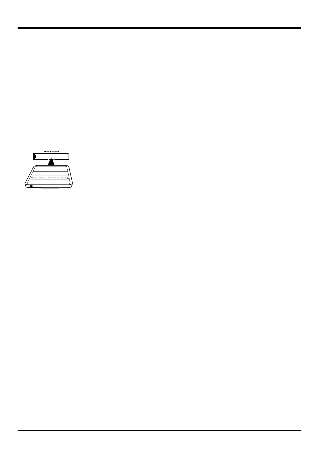
704
• Carefully insert the DATA card all the way in—until it is
firmly in place.
fig.M512-Insert
705
• Never touch the terminals of the DATA card. Also, avoid
getting the terminals dirty.
707
• Please use a separately available Roland PM-128-CF
CompactFlash card with the memory card adaptor supplied
with this unit. Operation with other media is not guaranteed.
708
• Memory cards are constructed using precision components; handle the cards carefully, paying particular note to
the following.
• To prevent damage to the cards from static electricity,
be sure to discharge any static electricity from your
own body before handling the cards.
• Do not touch or allow metal to come into contact with
the contact portion of the cards.
• Do not bend, drop, or subject cards to strong shock or
vibration.
• Do not keep cards in direct sunlight, in closed vehicles, or
other such locations (storage temperature: -25 to 85˚ C).
• Do not allow cards to become wet.
• Do not disassemble or modify the cards.
Handling Hard Disks
811
• Once a hard disk fails to function normally, all data that
has been stored on it could be destroyed.
All hard disks eventually wear out.
We recommend that
you consider the hard disk not as a permanent storage site,
but as a place to store data temporarily. We also recommend
that you back up important performance and image data
that cannot be recorded again onto the external media that is
supported by your device. For instructions on how to make
such backups, refer to the owner’s manual for your device.
Note that Roland assumes no liability whatsoever,
including monetary compensation, for the loss of any
recorded content in the event of the malfunction of, or
physical damage to the hard disk, or for any direct or
incidental damages resulting from the loss of such data.
Precautions Regarding Setup and Use
812
• Certain hard disk setup procedures and usage conditions
may result in the corruption of recorded data, malfunctioning, or physical damage to the disk, so be sure to
observe the following precautions.
• Do not subject the hard disk to vibration or shock,
especially while the unit is in operation.
• Do not set up the unit in any location where it may be
affected by vibration from external sources, or on any
surface that is not stable and level.
• If the device includes a cooling fan, ensure that the fan
and the side panel air vents remain unobstructed.
• Do not leave the unit in any environment subject to
temperature extremes; for example, in a closed
automobile in summer or outdoors during winter.
• Do not use the unit in conditions of high temperature
and humidity or in any location subject to rapid
temperature changes.
• Do not unplug the power cord or switch off any circuit
breakers in the circuit to which the unit is connected
while the power is turned on.
• Do not move the unit while the power is turned on or
immediately after turning off the power. When transporting the unit, first turn off the power and confirm that
the display screen has gone off, disconnect the power plug,
then wait at least two minutes before moving the device.
Emergency Procedures
813
* The following procedures are to be used as emergency mea-
sures only, and are not recommended for normal operation.
• If the device fails to respond to operational commands or
does not complete operations, turn off the power. If the
power does not shut off following normal shutdown procedures, disconnect the power plug.
If the unit does not operate normally when the power is
turned on again, it may mean that the hard disk has been
damaged. In such instances, consult your dealer or the
nearest Roland Service Center. Note, however, that it may
not be possible to recover any data from the hard disk once
it has been lost.
If your device features drive check capabilities, use the
drive check function to regularly confirm that there are no
problems, even when the device is operating normally.
For more detailed information on the shutdown and drive
check procedures, refer to the Owner’s Manual.
8
Page 9

IMPORTANT NOTES
220
• All product names mentioned in this document are trademarks or registered trademarks of their respective owners.
234
• CompactFlash and are trademarks of SanDisk Corporation and licensed by CompactFlash association.
235
• Roland Corporation is an authorized licensee of the CompactFlash™ and CF logo ( ) trademarks.
981a
• Copyright to the internal data
Copyright to the data included in this product is the property of the respective copyright holder(s). For details, refer to the
included “License agreement.“
982
• The demo data of this unit is not transmitted from the MIDI OUT connector.
985
• The explanations in this manual include illustrations that depict what should typically be shown by the display. Note,
however, that your unit may incorporate a newer, enhanced version of the system (e.g., includes newer sounds), so what you
actually see in the display may not always match what appears in the manual.
9
Page 10

Contents
Main Features.................................................................................................................................. 12
How to read this manual ................................................................................................................13
Panel Descriptions .........................................................................................................................14
Front Panel............................................................................................................................................................... 14
Rear Panel ................................................................................................................................................................17
Before you begin ............................................................................................................................18
About the card adaptor.......................................................................................................................................... 18
Connecting the card adaptor ..................................................................................................................18
Inserting/removing a CompactFlash card ........................................................................................... 19
About CompactFlash cards...................................................................................................................................20
Types of CompactFlash cards that you can use...................................................................................20
Projects and image files that can be stored on a CompactFlash card ............................................... 20
Formatting a CompactFlash card........................................................................................................... 20
Precautions concerning the handling of CompactFlash cards........................................................... 20
What is V-LINK?..................................................................................................................................................... 21
Making the connections.................................................................................................................22
Basic connections....................................................................................................................................................22
Example setups .......................................................................................................................................................23
VJ performance .........................................................................................................................................23
Using a sequencer to control the CG-8.................................................................................................. 24
Using images played by the CG-8 as video sources............................................................................ 25
Basic operation...............................................................................................................................26
Turning the power on/off..................................................................................................................................... 26
Turning the power on..............................................................................................................................26
Turning the power off.............................................................................................................................. 26
How the CG-8 is organized................................................................................................................................... 27
Images ........................................................................................................................................................ 27
Projects .......................................................................................................................................................28
Patches, Effects, and Pictures.................................................................................................................. 29
Selecting a project ...................................................................................................................................................31
Selecting a Photo Patch and playing back the image ........................................................................................32
Selecting a Photo Patch............................................................................................................................ 32
Selecting a Stamp Patch to layer on the image................................................................................................... 33
Selecting a Stamp Patch........................................................................................................................... 33
Applying an effect to the image ...........................................................................................................................34
Various playback methods ............................................................................................................ 36
Using the XY pad to apply effects to the image.................................................................................................36
Using the D Beam to apply effects to the image ................................................................................................ 37
Using the D Beam to momentarily pause image movement .............................................................37
Using the D Beam to apply an effect .....................................................................................................38
Recording and reproducing the motion of an image ........................................................................................39
Cueing or pausing the image (the Trigger function)......................................................................................... 40
Using an external audio input source to control the image (Sound Control function)................................ 41
Switching patches automatically (Auto Switch function) ................................................................................ 43
Using a foot pedal................................................................................................................................................... 44
Using a foot pedal to switch patches (Pedal Shift function) ..............................................................44
Learning more about the CG-8 ......................................................................................................45
How the CG-8 is structured .................................................................................................................................. 45
Play mode ................................................................................................................................................................ 49
Menu mode.............................................................................................................................................................. 49
Main menu screen (MAIN MENU) .......................................................................................................49
10
Page 11

Contents
About projects ................................................................................................................................50
What is a project?.................................................................................................................................................... 50
Creating a new project...........................................................................................................................................51
Assigning a project to a visual pad......................................................................................................................54
Editing a project......................................................................................................................................................57
Images that you can use as a Photo Picture or Stamp Picture...........................................................57
Assigning a Photo Picture or Stamp Picture to a visual pad .............................................................57
Creating patches............................................................................................................................. 61
Before you create patches......................................................................................................................................61
The content that is stored in a patch...................................................................................................... 61
Preparations before creating a patch .....................................................................................................61
Creating a Photo Patch ..........................................................................................................................................62
Selecting a Photo Patch............................................................................................................................ 62
Selecting a Photo Effect ........................................................................................................................... 63
Selecting a Photo Picture.........................................................................................................................64
Editing the parameters of a Photo Effect ..............................................................................................65
Applying modulation to the parameters of a Photo Effect ................................................................ 66
Making XY pad, D Beam, and Foot Pedal settings.............................................................................. 68
Saving a Photo Patch (the Save operation) ...........................................................................................72
Creating a Stamp Patch.......................................................................................................................................... 73
Selecting a Stamp Patch........................................................................................................................... 73
Selecting a Stamp Effect........................................................................................................................... 74
Selecting a Stamp Picture ........................................................................................................................75
Editing the parameters of a Stamp Effect .............................................................................................76
Applying modulation to the parameters of a Stamp Effect ...............................................................77
Making XY pad, D Beam, and Foot Pedal settings.............................................................................. 79
Saving a Stamp Patch (the Save operation) ..........................................................................................83
Managing projects and pictures.................................................................................................... 84
Folder and file related operations ........................................................................................................................84
Copying.................................................................................................................................................................... 85
Deleting....................................................................................................................................................................89
Renaming.................................................................................................................................................................91
Creating a folder .....................................................................................................................................................94
Formatting a CompactFlash card.........................................................................................................................97
Caution when formatting........................................................................................................................ 97
Formatting procedure.............................................................................................................................. 97
Adjusting the sensitivity of the controllers..................................................................................99
Adjusting the sensitivity of the XY pad and D Beam........................................................................................ 99
Using external equipment to control the CG-8 ..........................................................................101
Using V-LINK .......................................................................................................................................................101
Using MIDI equipment........................................................................................................................................ 103
Setting the device number..................................................................................................................... 103
Setting the MIDI transmit/receive channel........................................................................................ 105
Specifying the MIDI messages that will be sent from the CG-8......................................................107
MIDI messages and functions ..............................................................................................................109
Appendix .......................................................................................111
Photo Effects List .........................................................................................................................112
Stamp Effects List ........................................................................................................................119
MIDI Implementation Chart ..........................................................................................................122
Troubleshooting ...........................................................................................................................123
Restoring the factory settings.....................................................................................................124
Specifications ...............................................................................................................................125
Special thanks............................................................................................................................... 126
Index ..............................................................................................................................................127
11
Page 12

Main Features
An instrument that lets you present images in real time
You can generate images in real time, and use controllers such as the knobs, D Beam, and XY pad to freely
perform the images.
Diverse effects
The CG-8 provides a wide range of visual effect patterns that you can use to easily create expressive
images.
Load images to create a variety of expressions
Via the card adaptor, you can load images you’ve created with a digital camera or computer, and easily
give them an entirely different character. A wide range of expressive transformations can be created by
applying effects to the images you load.
Combine two image layers
You can combine two layers (background and foreground); for example, by adding a logo or other
foreground to a background image to project your message effectively.
Use music to control images
The CG-8 can analyze sound from its LINE IN jacks or internal mic, and apply a visual effect accordingly.
Peaks in the sound can be detected and used to create motion in the images or to switch patches.
Control via MIDI
In addition to controlling images via V-LINK as part of a musical performance, you can also control the
CG-8’s images via MIDI from a sequencer.
12
Page 13

How to read this manual
The CG-8 owner’s manual is organized as shown below. If you’re using the CG-8 for the first time, please read
“Basic operation”
equipment, and explains basic operations, from turning on the power to playing back images.
For more details, refer to the sections listed below.
Panel Descriptions (p. 14)
This explains the CG-8’s knobs, buttons, and connectors.
Before you begin (p. 18)
This explains how to use the card adaptor and CompactFlash cards.
Making the connections (p. 22)
This explains how to connect other equipment such as a television or projector to the CG-8, and various
ways in which you can use it.
Basic operation (p. 26)
This explains how to turn the power on, and describes the basic work flow on the CG-8.
Various playback methods (p. 36)
This explains the various ways in which you can play back images using the CG-8.
Learning more about the CG-8 (p. 45)
This explains concepts and terms you’ll need to know when using the CG-8, and describes the operating
screens and basic structure of the CG-8.
About projects (p. 50)
This explains project-related operations, such as how to load images into the CG-8.
Creating patches (p. 61)
This explains how to create and save your own photo patches and stamp patches.
Managing projects and pictures (p. 84)
This explains how to copy/delete/rename projects or images, and how to format a CompactFlash card.
Adjusting the sensitivity of the controllers (p. 99)
This explains how to adjust the sensitivity of the XY pad and D Beam.
Using external equipment to control the CG-8 (p. 101)
This explains how you can control the CG-8 from a V-LINK compatible device or a MIDI device.
Appendix (p. 111)
This section contains an effect list, troubleshooting tips, and the CG-8’s specifications.
(p. 26). This chapter helps you make sure that the CG-8 is correctly connected to your other
13
Page 14

Panel Descriptions
Front Panel
fig.frontpanel.eps
1
7 138 9 10 1165432
12
35
34
33
32
1.
D-BEAM
You can apply a variety of effects to the image by moving
your hand above this. → p. 37, p. 68, p. 79
2.
D-BEAM indicator
This will light when the D Beam is responding.
→
p. 37, p. 68, p. 79
3.
STROBE button
If you press this (button lit) and place your hand over the
D Beam, the image will stop momentarily. → p. 37
4.
ASSIGNABLE button
If you press this (button lit) and place your hand over the
D Beam, the effect specified for each patch will be applied.
→
p. 38
21222324252627293031 28
5.
REC button
This button records movements of the parameter knobs,
XY pad, and D Beam for ten seconds. Recording will
begin when you press the button (lit red).
→
p. 39
6.
GRAB MOTION switch
This plays back the parameter knob, XY pad, and D Beam
movements you recorded using the [REC] button.
LOOP:
OFF:
1-SHOT:
→
p. 39
The recorded movement will play repeatedly.
The patch will play normally.
The recorded movement will play. When you
release your hand from the switch, it will
return to the [OFF] position and the patch will
play normally.
14
15
16
17
18
19
20
14
Page 15

7.
TRIGGER switch
This cues or pauses the image.
RESTART:
OFF:
STROBE:
→
p. 40
8.
INPUT SELECT switch
This selects whether the external audio input will be taken
from the [LINE IN] jacks or from the internal mic. → p. 41
9.
Internal mic
Use this mic when you want to use the Sound Control
function.
→
p. 41
10.
INPUT LEVEL knob, SIGNAL indicators, PEAK indicators
Turn the [INPUT LEVEL] knob to adjust the input level
of the audio signal from an external source.
When an audio signal is received, the [SIGNAL] indicator
will light blue. If the input level is too high, the [PEAK]
indicator will light red.
→
p. 41
11.
PEAK FREQ knob, DETECTION indicator
Turn the [PEAK FREQ] knob to specify the center frequency
at which the external input audio will be analyzed.
The [DETECTION] indicator will light when a peak is
detected.
→
p. 41
12.
SPEED knob, SPEED indicator
If the [AUTO SWITCH] switch is set to [SPEED], this knob
adjusts the speed at which the patch will change. The patch will
change at the timing at which the [SPEED] indicator lights.
→
p. 43
13.
AUTO SWITCH switch
This switches patches automatically.
SPEED:
OFF:
SOUND:
→
p. 43
14.
SHUTDOWN button
When the power is on, you can press and hold this button
(for two seconds) to put the CG-8 in standby mode. In
standby mode, press this button to turn the CG-8 on.
The illumination of the button indicates the unit’s status
as follows:
Lit blue:
Lit red:
Unlit:
→
p. 26
Cues the image. When you release your hand,
the switch will return to the [OFF] position
and the patch will play normally.
The patch will play normally.
Pauses the image. When you release your
hand, the switch will return to the [OFF]
position and the patch will play normally.
The patch will switch at the speed specified by
the [SPEED] knob.
The patch will play normally.
The patch will switch when the peak specified
by the Sound Control function is detected.
On
Standby
Off
Panel Descriptions
15.
HDD indicator
This will light when the CG-8 is accessing its internal
hard disk.
* Never switch off the CG-8’s power while it is accessing the
hard disk.
16.
MIDI indicator
This will blink when the CG-8 receives a MIDI message.
17.
Display panel
This is used mainly to display the bank and number of
patches, effects, and pictures. It also displays various
information about the CG-8.
18.
PREVIEW button
By pressing this (the button will light), you can preview
all pictures in the currently selected bank.
→
p. 64, p. 75
19.
SAVE button
This saves the patch. → p. 72, p. 83
20.
VISUAL PAD 1–16
Use these to switch projects, patches, effects, pictures,
and banks.
→
p. 31, p. 32, p. 33, p. 62, p. 73
21.
EFFECT pad
Press this (the pad will light), and you can use visual
pads [1]–[16] to switch the effect for the currently selected
patch.
By holding down this button and pressing a visual pad
[1]–[16] you can switch banks.
→
p. 63, p. 74
22.
PICTURE pad
Press this (the pad will light), and you can use visual
pads [1]–[16] to switch the picture for the currently
selected patch.
By holding down this button and pressing a visual pad
[1]–[3] you can switch banks.
→
p. 64, p. 75
23.
STAMP PATCH pad
Press this (the pad will light) to perform Stamp Patch
operations or use visual pads [1]–[16] to switch stamp
patches.
By holding down this button and pressing a visual pad
[1]–[8] you can switch banks.
→
p. 33, p. 73
15
Page 16

Panel Descriptions
24.
PHOTO PATCH pad
Press this (the pad will light) to perform Photo Patch
operations or use visual pads [1]–[16] to switch photo
patches.
By holding down this button and pressing a visual pad
[1]–[8] you can switch banks.
→
p. 32, p. 62
25.
CHANGE PROJECT button
Press this (the button will light) to use visual pads [1]–
[16] to switch projects (visual pads to which a project is
assigned will light). In the display panel, the left side
shows the currently selected project, and the right side
shows the number of the project that will be selected
next. When you press the [CHANGE PROJECT] button
once again, the selected project will begin loading.
→
p. 31
26.
EXIT button, ENTER button, PREV button,
NEXT button, VALUE dial
By using these buttons and this dial while viewing the
menus that appear in the display screen, you can assign
photo pictures and stamp pictures, manage projects and
image files, and make MIDI settings for the CG-8.
→
p. 50, p. 84, p. 101
27.
MENU button
Press and hold this button for two seconds or longer to
access the MAIN MENU screen.
→
p. 49
28.
CONTROLLER ASSIGN button
Press this button when you want to make assignments for
the XY pad, D Beam, and foot pedal.
→
p. 68, p. 79
29.
HOLD button
This switches Hold on/off for the effect controlled by the
XY pad.
→
p. 36
30.
XY PAD ACTIVE indicator
This will light when the XY pad is responding.
→
p. 36, p. 68, p. 79
31.
XY pad
By touching your fingertip to the surface of this pad you
can apply a variety of effects to the image.
→
p. 36, p. 68, p. 79
32.
RATE knob
This adjusts the speed of modulation for the effect.
→
p. 34, p. 66, p. 77
33.
DEPTH button
Press this (the button will light) and you can use the
[COLOR]/[SPEED]/[X]/[Y]/[Z] knobs to adjust the
depth of modulation.
→
p. 34, p. 66, p. 77
34.
MODULATION knob
This selects the type of effect modulation. If you choose
[SOUND 1], [SOUND 2], or [SOUND 3], the external
audio input will modulate the effect.
→
p. 34, p. 66, p. 77
35.
Parameter knobs
These knobs adjust various parameters of the effect.
→
p. 34, p. 65, p. 66, p. 76, p. 77
The result will differ according to the effect, but the
knobs mainly control the following parameters.
k
COLOR
Adjusts a color-related parameter.
When the [DEPTH] button is pressed (the button will
light), this knob adjusts the depth of modulation.
SPEED knob:
Adjusts a speed-related parameter of the effect itself.
When the [DEPTH] button is pressed (the button will
light), this knob adjusts the depth of modulation.
FADE knob:
Adjusts a fade-related parameter. Turn toward the left to
fade-to-black, or toward the right to fade-to-white.
X knob:
Adjusts an X-axis (left/right) parameter such as X-axis or
angle of rotation.
When the [DEPTH] button is pressed (the button will
light), this knob adjusts the depth of modulation.
Y knob:
Adjusts a Y-axis (up/down) parameter such as Y-axis or
angle of rotation.
When the [DEPTH] button is pressed (the button will
light), this knob adjusts the depth of modulation.
Z knob:
Adjusts a Z-axis (forward/back) parameter such as Zaxis or angle of rotation.
When the [DEPTH] button is pressed (the button will
light), this knob adjusts the depth of modulation.
nob:
16
Page 17

Rear Panel
fig.rearpanel.eps
1 32
1.
POWER switch
This turns the power on.
You can press this again to turn the power off, but
before you turn the power off, make sure that the
[SHUTDOWN] button is lit red (Standby mode).
→
p. 26
2.
MIDI OUT/THRU connector, MIDI IN connector
You can connect external MIDI devices to these
connectors.
3.
Security slot ( )
You can connect a commercially available security lock
cable to this slot.
http://www.kensington.com/
4.
OUTPUT VIDEO jack
This jack outputs a video signal. You can connect it to
your television or other device used for monitoring.
→
p. 22
988
Panel Descriptions
54679810
6.
OPTION connector
Connect the included card adaptor here.
→
p. 18
7.
OUTPUT RGB connector
Connect a display here. Use a display that provides an
analog RGB D-sub 15-pin connection at VGA (640 x 480)
resolution.
→
p. 22
8.
LINE IN L/R jacks
Connect an instrument or CD player to these jacks.
→
p. 22
9.
FOOT SW jack
Connect a separately available foot pedal (e.g., DP-2) or
expression pedal (e.g., EV-5) to this jack. → p. 44
10.
AC IN connector
Connect the included power cord here.
5.
OUTPUT S-VIDEO connector
This connector transmits an S-video signal. You can
connect it to your television or other device used for
monitoring.
→
p. 22
17
Page 18

Before you begin
930
About the card adaptor
Use the included card adaptor to load image files from a digital camera or computer.
* The card adaptor is only for use with the CG-8. Don’t use it with a conventional computer.
* Don’t remove the CompactFlash card while data is being loaded from the card. Doing so may
destroy the data on the CompactFlash card.
* Don’t connect more than one card adaptor simultaneously.
* CompactFlash cards are not included with the CG-8. You will need to obtain them separately.
Connecting the card adaptor
Make sure that the CG-8’s power is switched off, then connect the card adaptor to the
rear panel [OPTION] connector as shown below.
fig.Card02.e.EPS
Don’t connect or
disconnect the card
adaptor while the CG-8 is
powered up.
Card adaptor
18
Page 19

Inserting/removing a CompactFlash card
931
This adaptor is for use with CompactFlash cards.
* We cannot guarantee that it will operate correctly with any media other than CompactFlash
cards.
930
* Do not insert or remove the supplied memory card adaptor while the unit is powered up.
Do not insert or remove a memory card while the memory card adaptor's indicator is
blinking. Doing so may cause the data in the memory card to be lost.
Inserting a CompactFlash card
* Don’t attempt to insert two or more cards simultaneously.
* Carefully note the end that should go in first, and the side that should face upward, then push
the CompactFlash card into the slot as far as it will go. Do not use excessive force.
Insert the CompactFlash card into the card adaptor as shown below.
fig.Card04.EPS
Before you begin
Carefully note the end that
should go in first, and the
side that should face
upward, then push the
CompactFlash card into
the slot as far as it will go.
Do not use excessive force.
Removing a CompactFlash card
When you insert a CompactFlash card, the button located beside the card slot will pop
out.
When you press this button, the inserted CompactFlash card will pop out, allowing
you to remove it.
fig.Card05.EPS
19
Page 20

Before you begin
b
About CompactFlash cards
Types of CompactFlash cards that you can use
The CG-8 can store projects and image files on a CompactFlash card. Insert a separately
available Roland PM-128-CF (128 MB) CompactFlash card into the included card
adaptor. We do not guarantee operation with other media.
Roland CompactFlash card:
Projects and image files that can be stored on a CompactFlash card
Any number of project and image files can be stored on a CompactFlash card up to the
capacity of that card.
In a file name, you can use lowercase letters (a–z), numerals (0–9), and the symbols “” (hyphen) and “_” (underline). If a file whose file name contains uppercase letters is
saved on a CompactFlash card, the CG-8 will automatically convert the uppercase
characters to lowercase.
When saving image files to a CompactFlash card on your computer, you must add an
extension to the filename. The CG-8 will not recognize files that have no extension.
The CG-8 will not recognize files whose name contains characters that cannot be used
(A–Z, a–z, 0–9, -, _).
PM-128-CF (128 MB)
For details on the types of
image files that you can
use with the CG-8, refer to
“Images that you can
use as a Photo Picture or
Stamp Picture” (p. 57).
Formatting a CompactFlash card
Before you can use a newly purchased CompactFlash card or a CompactFlash card
that’s been used by a different device, you’ll need to format (initialize) that card.
Caution when formatting
Formatting will erase all of the data on the card. Be sure to double-check before you
format a card.
Formatting procedure
Cards are formatted in the FILE MANAGER screen. For details, refer to
a CompactFlash card”
(p. 97).
Precautions concerning the handling of CompactFlash cards
When inserting
Carefully note the end that should go in first, and the side that should face upward, then
push the CompactFlash card into the slot as far as it will go. Do not use excessive force.
When removing
Grasp the card with your fingers and pull it straight out.
Never remove the card while loading, saving, or formatting is in progress. Also, you
must never turn off the power of the CG-8 or disconnect the power cord while loading,
saving, or formatting is in progress. Doing so may damage the CompactFlash card.
“Formatting
Static electricity can occur
more easily in conditions
of low humidity. Before
inserting or removing a
CompactFlash card, touch
a metal component of the
CG-8 to discharge any
static electricity that may
e present in your body.
20
Page 21

What is V-LINK?
V-LINK ( ) is a capability that lets you link musical and visual
performance. V-LINK lets you easily control visual processing that is linked with
certain expressive elements of a musical performance. For example, a V-LINK
compatible MIDI device can be used to control the CG-8.
fig.vlink-con1.e
V-Synth
Remote functions
(V-LINK)
MIDI cable
Before you begin
CG-8
Video output
For details on using V-LINK, refer to
“Using V-LINK”
Display or projector
(p. 101).
21
Page 22

Making the connections
Basic connections
Use the [OUTPUT RGB] connector if you are connecting the CG-8 to a computer display or projector. Use
the [OUTPUT S-VIDEO] connector or [OUTPUT VIDEO] connector if you are connecting the CG-8 to a
television or projector. If desired, connect the included card adaptor to the [OPTION] connector (p. 18).
If you’re using the CG-8’s Sound Control function with an external audio source connected to the [LINE
IN] jacks, connect your audio device (e.g., CD player) to these jacks. For details, refer to
external audio input source to control the image (Sound Control function)”
921
926a
* To prevent malfunction or damage, you must minimize the volume of all devices and turn off the power before
connecting other devices.
* The volume from the device connected to the [LINE IN] jacks may be diminished if you use a cable with a built-in
resistor to make connections. If so, use a connection cable that does not contain a resistor (e.g., the Roland PCS
series of cables).
fig.connect.e.eps
Computer display or projector
“Using an
(p. 41).
Television or projector
S-VIDEO output VIDEO output
Rear panel
Analog RGB output (VGA)
Power cord
LINE IN L/R OPTIONAC IN
to an AC outlet
Card adaptor
Foot pedal
(e.g., DP-2)
* For details on the card adaptor, refer to
* You can connect a foot pedal (foot switch or expression pedal) and use it to control the CG-8’s parameters. For
details, refer to
“Using a foot pedal”
CD player, etc.
“About the card adaptor”
(p. 44).
(p. 18).
22
Page 23

Example setups
VJ performance
The following illustration is an example of connections for using the CG-8 in a VJ performance.
If you’re using V-LINK (p. 101) to control the CG-8 from the V-Synth, make connections as follows.
fig.connect.v-link.e.EPS
V-Synth
Making the connections
CG-8
MIDI cable
Audio cable
CD player, etc.
Display or projector
If you’re controlling the CG-8 from the MC-909, make connections as follows.
fig.connect.MC909.e.EPS
MC-909
MIDI cable
Audio cable
VGA cable
Video cable
S-video cable, etc.
CG-8
VGA cable
Video cable
S-video cable, etc.
CD player, etc.
Display or projector
23
Page 24

Making the connections
Using a sequencer to control the CG-8
If you’re using MIDI functions (p. 103) to control the CG-8 from sequencer software running on your
computer, make connections as follows.
fig.connect.CPU.e.EPS
MIDI interface
(e.g., UM-550)
CG-8Computer
USB cable
MIDI cable
Display or projector
VGA cable
Video cable
S-video cable, etc.
24
Page 25

Using images played by the CG-8 as video sources
With a setup such as shown below, images played by the CG-8 can be used as video sources and received
by a video device such as the DV-7DL.
fig.connect.DV.e.EPS
DV-7DLCG-8
Scan
rate
converter
Video cable
VGA cable
Video cable
S-video cable, etc.
Display or projector
Making the connections
25
Page 26

Basic operation
b
This section explains basic operation.
Turning the power on/off
941
942
* Once the connections have been completed, turn on power to your various devices in the order
specified. By turning on devices in the wrong order, you risk causing malfunction and/or
damage to speakers and other devices.
1. Connected equipment
2. CG-8
* This unit is equipped with a protection circuit. A brief interval (a few seconds) after power
up is required before the unit will operate normally.
Turning the power on
fig.front01.e.eps
[SHUTDOWN] button [POWER] button
1
Check the connections as described in
power of the display or monitor television that’s connected to the CG-8.
2
Press the [POWER] switch located on the rear panel of the CG-8.
The [SHUTDOWN] button will light blue, and the CG-8 will begin starting up.
It will take a short time for the CG-8 to start up. (The display panel will indicate
“Load.”)
When the CG-8 has started up, the display panel will indicate “– –”.
“Basic connections”
(p. 22)
, and turn on the
Before pressing the
[POWER] switch to turn off
the power, make sure that
the [SHUTDOWN] button
is lit red, indicating that the
CG-8 is in Standby mode.
Turning the power off
1
Press and hold the [SHUTDOWN] button for two seconds or longer.
The [SHUTDOWN] button will blink red/blue (shutdown in progress).
After a time, the [SHUTDOWN] button will light red (standby mode).
2
Press the [POWER] switch located on the CG-8’s rear panel.
945
The [SHUTDOWN] button’s light goes out.
* If you need to turn off the power completely, first turn off the POWER switch, then unplug
the power cord from the power outlet. Refer to
“Power Supply”
(p. 7).
When the [SHUTDOWN]
utton is lit red, the CG-8 is
in Standby mode; the
power is not turned off. To
turn the power off
completely, press the
[POWER] switch so the
[SHUTDOWN] button’s
illumination is turned off.
26
Page 27

How the CG-8 is organized
Before you actually begin operating the CG-8, please read this section to become
familiar with how it is organized.
When you’re ready for more detail, refer to
Images
To generate a video image on the CG-8, you select “patches,” which are the minimum
unit of video data. There are two kinds of patches; Photo Patches produce the
background image, and Stamp Patches are superimposed on this background.
fig.photo&stamp01.e.EPS
Stamp Patch (foreground)
“Learning more about the CG-8”
Basic operation
(p. 45).
Photo Patch (background)
Photo Patches and Stamp Patches each consist of a “picture” (image) and an “effect”
for the photo or stamp.
fig.photo&stamp02.e.EPS
Photo Patch
Picture Effect
Modify the location of
the image or apply
various effects
In addition, each effect can apply change or movement to the picture. You can also
create a variety of visual effects by controlling the location and movement parameters.
You can also use controllers such as the XY pad and D Beam to control the image in real
time.
Resulting image
Stamp Patch
Picture Effect
Modify the location of
the image or apply
various effects
27
Page 28

Basic operation
Projects
On the CG-8, the “project” is the most basic unit by which data is managed. A project
contains patches and the images used by those patches. By switching between projects
you can use a large number of patches.
fig.structure04.e.EPS
For more about projects,
refer to “About projects”
(p. 50).
Project
Photo
Picture
Assign the
desired Photo Picture.
Stamp
Picture
Assign the
desired Stamp Picture.
Photo Patch
Photo
Picture
Stamp Patch
Stamp
Picture
+
+
Photo
Effect
Select and
play back the
desired Photo
Patch.
Stamp
Effect
Select and
play back the
desired Stamp
Patch.
28
Page 29

Patches, Effects, and Pictures
Patches (Photo Patches and Stamp Patches)
Photo Patches and Stamp Patches are managed by their bank and number as shown
below. You can recall them by using Visual Pads [1]–[16].
fig.patch.e.eps
Bank 8
Bank 1
Photo Patches
A single project can contain up to 128 (16 patches x 8 banks) Photo Patches and Stamp
Patches.
Bank 8
Bank 1
Stamp Patches
Basic operation
For details on creating and
saving Photo Patches and
Stamp Patches, refer to
“Creating patches” (p.
61).
Photo Patches →
Stamp Patches →
p. 62
p. 73
Effects (Photo Effects and Stamp Effects)
The CG-8 provides more than 200 effects for Photo Patches, and more than 60 effects
for Stamp Patches.
These are respectively called “Photo Effects” and “Stamp Effects,” and are managed by
their bank and number in the same way as patches. You can switch effects by using
Visual Pads [1]–[16].
fig.effect.e.eps
Bank --
Bank 1
Photo Effects
Photo Effects →
Stamp Effects →
p. 63
p. 74
Bank --
Bank 1
Stamp Effects
For details on the contents
of the Photo Effects, refer
to “Photo Effects List” (p.
112). For details on the
contents of the Stamp
Effects, refer to “Stamp
Effects List” (p. 119).
29
Page 30

Basic operation
Pictures (Photo Pictures and Stamp Pictures)
Image files stored on the internal hard disk or on a CompactFlash card can be loaded
into a project and assigned to visual pads [1]–[16] so that they can be used as pictures
in Photo Patches or Stamp Patches.
These are respectively called “Photo Pictures” and “Stamp Pictures,” and are managed
by bank and number in the same way as the patches and effects described earlier.
fig.picture.e.eps
Bank 3
Bank 2
Bank 1
Bank 1
For details on how to load
a picture into a project and
assign it to a visual pad,
refer to “Editing a
project” (p. 57).
Photo Pictures
Stamp Pictures
A single project can use up to 48 Photo Pictures (16 x 3 banks) and up to 16 Stamp
Pictures.
Photo Pictures →
Stamp Pictures →
* For more details about how the CG-8 is organized, refer to
CG-8”
(p. 45).
p. 64
p. 75
“Learning more about the
30
Page 31

Selecting a project
b
Here’s how to select a project.
You can use the visual pads to easily select a project.
* You can’t load a project that’s not assigned to a visual pad. For details, refer to
a project to a visual pad”
fig.front16.e.eps
1
Press the [CHANGE PROJECT] button.
The button will light.
Of the visual pads [1]–[16], pads to which a project is assigned will light.
The left side of the display panel will indicate the number of the visual pad to which
the currently selected project is assigned, and the right side of the display panel will
blink “–”.
2
To select a project, press a visual pad [1]–[16] that is lit.
(p. 54).
[CHANGE PROJECT] button
Basic operation
“Assigning
If after pressing the
[CHANGE PROJECT]
utton you decide to
cancel the operation, press
the [EXIT] button.
The visual pad you pressed and the [CHANGE PROJECT] button will blink.
In the right side of the display panel, the number of the visual pad you pressed will
blink.
3
Press the [CHANGE PROJECT] button.
The button will go out, and the CG-8 will begin loading the selected project.
The display panel will indicate “Load.”
When the selected project has finished loading, the display panel will indicate “– –”.
The project has finished loading. Now let’s select a Photo Patch and Stamp Patch, and
play back the image.
31
Page 32

Basic operation
b
Selecting a Photo Patch and playing back the image
Now we’re actually going to play back an image using the CG-8.
First, select a “Photo Patch” to play back as the background image.
Selecting a Photo Patch
fig.front02.e.eps
For details on creating and
saving a Photo Patch, refer
[PHOTO PATCH] pad
Visual pads [1]–[16]
1
Press the [PHOTO PATCH] pad.
The [PHOTO PATCH] pad will light.
Of visual pads [1]–[16], those for which a Photo Patch has been saved will light.
2
Press one of the lit visual pads [1]–[16] to select a patch.
The selected Photo Patch will begin playing. The display panel will indicate the bank
and number of that Photo Patch.
to “Creating a Photo
Patch” (p. 62).
The Photo Patch will not
change if you press a
visual pad that is not
illuminated (i.e., a pad to
which no Photo Patch has
een assigned).
Switching banks and selecting a Photo Patch
1
To switch banks, hold down [PHOTO PATCH] and press a visual pad [1]–[8].
While you continue holding down the [PHOTO PATCH] pad, the visual pad of the
currently selected bank number will blink.
2
When you take your finger off the [PHOTO PATCH] pad, visual pads [1]–[16] in
which a Photo Patch is saved will light.
3
Press one of the lit visual pads [1]–[16] to select a patch.
The selected Photo Patch will begin playing. The display panel will indicate the bank
and number of that Photo Patch.
32
Page 33

Selecting a Stamp Patch to layer on the image
b
Next we’ll select a “Stamp Patch” image for the foreground, and layer it onto the
background. You will use this mainly for a logo or text that explains the background.
Selecting a Stamp Patch
fig.front05.e.eps
[STAMP PATCH] pad
Visual pads [1]–[16]
Basic operation
1
Press the [STAMP PATCH] pad.
The [STAMP PATCH] pad will light.
Of the visual pads [1]–[16], the pads to which a Stamp Patch has been saved will light.
2
Press one of the lit visual pads [1]–[16] to select a patch.
The selected Stamp Patch will begin playing. The display panel will indicate the bank
and number of that Stamp Patch.
Switching banks and selecting a Stamp Patch
1
Hold down the [STAMP PATCH] pad and press a visual pad [1]–[8] to switch banks.
While you continue holding down the [STAMP PATCH] pad, the visual pad of the
currently selected bank number will blink.
2
When you take your finger off the [STAMP PATCH] pad, visual pads [1]–[16] in
which a Stamp Patch is saved will light.
3
Press one of the lit visual pads [1]–[16] to select a patch.
The selected Stamp Patch will begin playing. The display panel will indicate the bank
and number of that Stamp Patch.
For details on creating and
saving a Photo Patch, refer
to “Creating a Stamp
Patch” (p. 73).
The Stamp Patch will not
change if you press a
visual pad that is not
illuminated (i.e., a pad to
which no Stamp Patch has
een assigned).
33
Page 34

Basic operation
Applying an effect to the image
You can use the knobs and buttons shown below to modify the settings of the Photo
Effect and Stamp Effect. In this way you can apply a wide range of changes to the Photo
Patch image and Stamp Patch image.
fig.front08.e.eps
[COLOR] knob
[SPEED] knob
[FADE] knob[MODULATION] knob
If you’ve modified the
settings of an effect, you
can save your changes
together with the picture
as a Photo Patch or Stamp
Patch. For details, refer to
“Creating patches” (p.
61).
Parameter knobs
[Z] knob[RATE] knob
[Y] knob[DEPTH] button
[X] knob
About the parameter knobs
The parameter knobs work in two different ways depending on the state of the
[DEPTH] button.
When the [DEPTH] button is off (unlit)
The parameter knobs will modify the image.
The [X] knob, [Y] knob, and [Z] knob will mainly change the position. The [SPEED]
knob adjusts the speed, the [COLOR] knob adjusts the color, and the [FADE] knob
adjusts the state of the fade. (Refer to the table on the next page.)
When the [DEPTH] button is on (lit)
The parameter knobs will adjust the modulation (cyclic change) of the image.
First, use the [MODULATION] knob to select the type of modulation (e.g., smooth
motion or random motion). Then, use the parameter knobs to adjust how that motion
is to occur. The [X] knob, [Y] knob, and [Z] knob will mainly change the direction of the
motion. The [SPEED] knob adjusts the speed of motion, and the [COLOR] knob adjusts
the color change (see the table on the following page). The [FADE] knob is not used
here.
The [RATE] knob adjusts the overall speed of modulation.
34
Page 35

You can apply effects separately to the Photo Patch and the Stamp Patch. When the
[PHOTO PATCH] button is lit, the effect applies to the Photo Patch. When the [STAMP
PATCH] button is lit, the effect applies to the Stamp Patch.
1
To apply an effect to the Photo Patch image, press the [PHOTO PATCH] pad. To
apply an effect to the Stamp Patch image, press the [STAMP PATCH] pad.
The corresponding pad will light.
2
Apply the effect to the image.
Using the parameter knobs
In general, the parameter knobs have the following effect.
[MODULATION] knob
[RATE] knob
[COLOR] knob
[SPEED] knob
[X] knob
[Y] knob
[Z] knob
Selects the type of modulation.
Adjusts the speed of modulation.
Adjusts the depth of color-related modulation.
Adjusts the depth of speed-related modulation.
Adjusts the modulation depth for X-axis (left/right)
modulation, such as X-position or rotational angle.
Adjusts the modulation depth for Y-axis (up/down)
modulation, such as Y-position or rotational angle.
Adjusts the modulation depth for Z-axis (forward/
backward) modulation, such as Z-position or rotational angle.
Basic operation
For details on Photo Effect
parameters, refer to
“Editing the parameters
of a Photo Effect” (p. 65)
For details on Stamp Effect
parameters, refer to
“Editing the parameters
of a Stamp Effect” (p. 76)
For details on the
parameters of each effect,
refer to “Photo Effects
List” (p. 112) and “Stamp
Effects List” (p. 119).
Depending on the effect,
there may be some
parameters that you
cannot adjust.
.
.
Adding modulation (motion) to the image
Press the [DEPTH] button so it is lit, and use the parameter knobs to adjust the
modulation of the image.
[MODULATION] knob
[RATE] knob
[COLOR] knob
[SPEED] knob
[X] knob
[Y] knob
[Z] knob
Selects the type of modulation.
Adjusts the speed of modulation.
Adjusts the depth of color-related modulation.
Adjusts the depth of speed-related modulation.
Adjusts the modulation depth for X-axis (left/right)
modulation, such as X-position or rotational angle.
Adjusts the modulation depth for Y-axis (up/down)
modulation, such as Y-position or rotational angle.
Adjusts the modulation depth for Z-axis (forward/
backward) modulation, such as Z-position or rotational angle.
For details on modulation
for a Photo Effect, refer to
“Applying modulation to
the parameters of a
Photo Effect” (p. 66). For
details on modulation for a
Stamp Effect, refer to
“Applying modulation to
the parameters of a
Stamp Effect” (p. 77).
35
Page 36

Various playback methods
By operating the front panel controls of the CG-8 you can “play back” images in a
variety of ways. This section explains these playback methods.
Using the XY pad to apply effects to the image
The XY pad, located on the left side of the front panel, is a controller that you operate
by touching it with your fingertip. You can use this to apply various effects to the
image.
To use the XY pad, you assign the desired effect parameter(s) to the pad, and then
control these parameters in real time to apply the effect to the image.
fig.front09.e
XY pad
[XY PAD ACTIVE]
indicator
For each patch, the choice
of parameter that will be
controlled by the XY pad
can be saved as part of the
patch settings. This lets
you create patches that
contain the most
appropriate controller
settings. For details, refer
to “Creating patches” (p.
61).
[HOLD] button
1
If you want to apply an effect to a Photo Patch, press the [PHOTO PATCH] pad. If
you want to apply an effect to a Stamp Patch, press the [STAMP PATCH] pad.
2
Move your finger left/right (X-axis) or up/down (Y-axis) on the XY pad. The effect
will be applied.
fig.XY.eps
When the XY pad is responding, the [XY PAD ACTIVE] indicator will light.
If you press the [HOLD] button (it will light), the effect will be maintained even if you
take your finger away from the XY pad.
For some patches or
effects, it may not be
possible to apply an effect.
For details on how to
adjust the sensitivity of the
XY pad, refer to
“Adjusting the sensitivity
of the controllers” (p. 99).
36
Page 37

Various playback methods
Using the D Beam to apply effects to the image
The D Beam, located in the upper left part of the front panel, is a sensor that detects the
position of your hand placed above it. You can use this to apply various effects to the image.
fig.front10.e.eps
D Beam
[STROBE] button
[ASSIGNABLE] button
[D-BEAM] indicator
You can’t use both the
Strobe function and the
Assignable function at the
same time.
The D Beam can be used either as a Strobe effect, which momentarily halts the
movement of the image (Strobe), or as a realtime controller for the effect parameter
you’ve assigned (Assignable), just as for the XY pad.
The D Beam’s range of detection
The illustration at right shows the range in which the
D Beam can detect the position of your hand. No effect will
be produced if you move your hand outside this range. The
[D-BEAM] indicator will light when the D Beam is
responding. If you move outside the D Beam’s range of
detection, the [D-BEAM] indicator will not light.
fig.DBEAM.eps
The D-Beam’s range of
detection will become
much smaller under
conditions of intense light.
Please be aware of this
when using the D Beam
outdoors or in very bright
locations.
For details on how to
adjust the sensitivity of the
D Beam, refer to
“Adjusting the sensitivity
of the controllers” (p. 99).
Using the D Beam to momentarily pause image movement
Here’s how to use the D Beam to momentarily pause the movement of the image
(Strobe effect).
Strobe is an effect that thins out the frames of the image while it is paused. The image
continues to flow in the background even while it is paused, and when you resume
from the paused state, the image will begin playing from the appropriate point on the
time axis.
* The strobe effect applies to both the Photo Patch and the Stamp Patch.
1
Press the [STROBE] button.
The button will light.
* If you press the [STROBE] button when the [ASSIGNABLE] button is lit (i.e., the Assignable
function is on), the [ASSIGNABLE] button will go out and the Assignable function will turn
off. The Strobe function and Assignable function cannot both be on at the same time.
2
Place your hand over the D Beam and the image will pause; playback will resume
when you remove your hand.
The [D-BEAM] indicator will light when the D Beam is responding.
3
Press the [STROBE] button; it will go out, and the D Beam will turn off.
For details on how
playback will occur when
you apply the Strobe
effect, refer to “How the
Strobe effect affects the
image” (p. 40).
37
Page 38

Various playback methods
Using the D Beam to apply an effect
As with the XY pad, you can also assign a specific effect parameter to the D Beam, and
use the D Beam to control the value of that parameter in real time (the Assignable
function).
1
If you want to apply an effect to a Photo Patch, press the [PHOTO PATCH] pad. If
you want to apply an effect to a Stamp Patch, press the [STAMP PATCH] pad.
2
Press the [ASSIGNABLE] button.
The button will light.
* If the [STROBE] button is lit (i.e., the Strobe function is on), pressing the [ASSIGNABLE]
button will turn off the [STROBE] button’s illumination and the Strobe function will turn
off. The Strobe function and the Assignable function cannot both be on simultaneously.
3
Place your hand over the D Beam, and slowly move it up and down to apply the
effect.
The left [D-BEAM] indicator will light when the left D Beam sensor is responding, the
right indicator when the right sensor is responding, and both indicators when both
sensors are responding.
4
Press the [ASSIGNABLE] button; the button will go out, and the D Beam will turn off.
For each patch, the choice
of parameter that will be
controlled by the D Beam
can be saved as part of the
patch settings. This lets
you create patches that
contain the most
appropriate controller
settings. For details, refer
to “Creating patches” (p.
61).
For some patches or
effects, it may not be
possible to apply an effect.
38
Page 39

Various playback methods
Recording and reproducing the motion of an image
The Grab Motion function lets you record up to ten seconds of an effect parameter
motion you created using the parameter knobs, XY pad, D Beam, or foot pedal (except
for the Patch Shift function), and play back this motion. This lets you reproduce
realtime changes in the image.
fig.front11.e.eps
[GRAB MOTION] switch
[REC] button
1
Press the [PHOTO PATCH] pad if you want to record a Photo Patch motion. Press the
[STAMP PATCH] pad if you want to record a Stamp Patch motion.
2
Press the [REC] button.
The button will light red, and recording will begin.
3
Operate the [COLOR] knob, [SPEED] knob, [FADE] knob, [X] knob, [Y] knob, [Z]
knob, XY pad, D Beam, or foot pedal.
* You can’t record motion for parameters that are related to effect modulation. This means that
if the [DEPTH] button is lit, you won’t be able to record movements of the [COLOR] knob,
[SPEED] knob, [X] knob, [Y] knob, or [Z] knob.
* You can’t record image motion produced by using the D Beam to apply the Strobe effect (p.
37).
For details on the
parameter knobs, refer to
“Applying an effect to
the image” (p. 34).
For details on the
parameters of each photo
effect, refer to “Photo
Effects List” (p. 112). For
details on the parameters
of each stamp effect, refer
to “Stamp Effects List”
(p. 119).
For details on how to use
the XY pad, refer to
“Using the XY pad to
apply effects to the
image” (p. 36).
4
Press the [REC] button to stop recording (the button will go out). Alternatively,
recording will stop automatically when ten seconds have elapsed.
5
Use the [GRAB MOTION] switch to play back the recorded motion.
[LOOP]
[OFF]
[1-SHOT]
The recorded motion will play back as a loop.
The patch will play normally. If you move the switch from
[LOOP] or [1-SHOT] to [OFF], the patch will play as it did
when you turned it [OFF].
The recorded motion will play back as long as you hold the
switch toward yourself. When you release the switch, it will
automatically return to the [OFF] position, and the patch will
play normally.
For details on how to use
the D Beam, refer to
“Using the D Beam to
apply effects to the
image” (p. 37).
For details on how to use a
foot pedal, refer to “Using
a foot pedal” (p. 44).
The motion you record
using the Grab Motion
function will be lost when
the CG-8’s power is
switched off.
39
Page 40

Various playback methods
b
Cueing or pausing the image (the Trigger function)
The Trigger function lets you easily cue or pause the image. Pausing the image will
apply a strobe effect just as when using the D Beam’s strobe effect. Strobe is an effect
that thins out the frames of the image while it is paused. The image continues to flow
in the background even while it is paused, and when you resume from the paused
state, the image will begin playing from the appropriate point on the time axis.
fig.front12.eps
[TRIGGER] switch
Use the [TRIGGER] switch to cue or pause the image.
[RESTART]
[OFF]
[STROBE]
When you move the switch to this position, it will be cued to
the beginning and playback will start. When you release the
switch, it will automatically return to the [OFF] position and
the patch will play normally.
The Trigger function will be off, and the patch will play normally.
The Strobe effect will be applied. The image will pause when
you pull the switch toward yourself. When you release the
switch, it will automatically return to the [OFF] position and
the patch will play normally.
How the Strobe effect affects the image
Example: Here’s what happens if you move the [TRIGGER] switch to the [STROBE]
position the instant the image reaches “3,” and then release the switch at “7.”
fig.strobe1.e.eps
3 4 5 6 7 821
[RESTART] applies either
to the Photo Patch or the
Stamp Patch. To choose
the desired patch, press
the [PHOTO PATCH] pad
or the [STAMP PATCH]
pad. [STROBE] applies to
oth the Photo Patch and
the Stamp Patch.
7 8321 456
Pause at “3”
Move the [TRIGGER] switch
to [STROBE].
Release the [TRIGGER] switch.
The image resumes from
“7.”
40
Page 41

Various playback methods
b
Using an external audio input source to control the image
(Sound Control function)
The CG-8’s Sound Control function lets you control the image by detecting the peaks
in an audio signal received from the internal mic or the [LINE IN] jacks. You can use
these detected audio peaks to control the timing at which an effect is modulated, or use
the audio peaks to switch patches automatically.
fig.front13.e.eps
[PEAK] indicator
[INPUT SELECT] switch
1
If you’re inputting audio via the CG-8’s internal mic, press the [INPUT SELECT]
switch so it is in the inward position. If you’re inputting audio from the rear panel
[LINE IN] jacks, press the [INPUT SELECT] switch so it is in the outward position.
2
Turn the [INPUT LEVEL] knob to adjust the input level.
The [SIGNAL] indicator will light blue when an audio signal is received. If the
indicator does not light, raise the input level (turn the knob toward the right).
If the input level is too high, the [PEAK] indicator will light red. If the indicator stays
lit, lower the input level (turn the knob toward the left).
3
Turn the [PEAK FREQ] knob to specify the center frequency at which you want to
detect peaks in the audio.
Turn the [PEAK FREQ] toward the left if you want to detect low-frequency peaks such
as bass drum, or toward the right if you want to detect high-frequency peaks such as
cymbal.
The [DETECTION] indicator will light when the CG-8 detects peaks in the region you
specify.
* As a special case, turning the [PEAK FREQ] knob all the way toward [LOW] will cause peak
detection to respond not to a specific frequency but to the overall power of the sound. In cases
such as when a very large number of instruments are playing, or when the sound is
continuously at a high volume, you may find it more useful to turn the knob all the way
toward [LOW].
Internal mic
[DETECTION] indicator
[PEAK FREQ] knob
[INPUT LEVEL] knob
[SIGNAL] indicator
The Sound Control
function won’t work
properly if the input level
is set inappropriately. If
you’re inputting audio
from a musical instrument,
adjust the level so that the
[PEAK] indicator lights
riefly when you play most
strongly.
41
Page 42

Various playback methods
4
You can use the Sound Control function in the following ways.
Modulating an effect at the timing of the detected audio peaks
Use the [MODULATION] knob to select [SOUND 1]–[SOUND 3], press the [DEPTH]
button so it is lit, and operate the parameter knobs. Modulation will be applied to the
parameter you control. The modulation will change according to the peak of the audio
input.
For details on modulating a Photo Effect, refer to
parameters of a Photo Effect”
to
“Applying modulation to the parameters of a Stamp Effect”
Switching patches at the detected audio peaks
If you want patches to switch automatically at the timing of the detected peaks, set the
[AUTO SWITCH] to [SOUND].
* Independently from the method of control using the peaks detected by the Sound Control
function, there are also effects that respond directly to sound. For these effects, the input level
adjusted by the [INPUT LEVEL] knob will directly affect how the effect behaves. For details,
refer to
“Photo Effects List”
“Applying modulation to the
(p. 66). For details on modulating a Stamp Effect, refer
(p. 77).
(p. 112) and
“Stamp Effects List”
(p. 119).
42
Page 43

Various playback methods
Switching patches automatically (Auto Switch function)
The Auto Switch function automatically switches the Photo Patch or Stamp Patch. You
can make the patch switch at a specified speed, or at the timing of an external audio
peak detected by the Sound Control function (p. 41).
* The Auto Switch function automatically switches patches within the currently selected bank.
If you want to switch to a patch in a different bank, you’ll need to switch the bank.
fig.front14.e.eps
[SPEED] indicator
[AUTO SWITCH] switch
[SPEED] knob
1
Press the [PHOTO PATCH] pad if you want to automatically switch Photo Patches, or
press the [STAMP PATCH] pad if you want to automatically switch Stamp Patches.
2
Use the [AUTO SWITCH] switch to select how patches should be switched
automatically.
[SPEED]
[OFF]
[SOUND]
Patches will switch at the speed specified by the [SPEED]
knob. The patch will switch the instant that the [SPEED] indicator (located above the knob) lights. Watch the indicator
while you turn the [SPEED] knob to adjust the speed.
The Auto Switch function will be off.
Patches will switch when external audio peaks are detected
as specified by the Sound Control function. The patch will
switch the instant the [DETECTION] indicator lights.
For details on how to
switch banks, refer to
“Switching banks and
selecting a Photo Patch”
(p. 32) and “Switching
banks and selecting a
Stamp Patch” (p. 33).
For details on using the
Sound Control to specify
an external audio input,
refer to “Using an
external audio input
source to control the
image (Sound Control
function)” (p. 41).
43
Page 44

Various playback methods
925
Using a foot pedal
You can connect a separately sold foot pedal (Roland DP-2 / DP-6) or expression pedal
(Roland EV-5 / EV-7) to the CG-8’s rear panel [FOOT SW] jack, and use it to switch
patches, or for realtime control of an effect parameter that you assign, just as when
using the XY pad or D Beam.
fig.rear02.e.eps
Foot pedal (DP-2)
The foot pedal assignment
can be saved separately for
each patch as part of the
patch settings. This lets
you create patches that
contain the most effective
settings for your situation.
For details, refer to
“Creating patches” (p.
61).
Use only the specified foot
switches or expression
pedals. Connecting a
switch or pedal made by
another manufacturer
could cause the CG-8 to
malfunction.
Using a foot pedal to switch patches (Pedal Shift function)
With the factory settings, the foot pedal setting is assigned to switch patches. Proceed
as follows.
1
Press the [PHOTO PATCH] pad if you want to switch Photo Patches, or press the
[STAMP PATCH] pad if you want to switch Stamp Patches.
2
Press the foot pedal to switch patches.
* Patches in the currently selected bank will be selected. If you want to select patches from
another bank, use the [PHOTO PATCH] pad or the [STAMP PATCH] pad to switch banks.
For details on how to
switch banks, refer to
“Switching banks and
selecting a Photo Patch”
(p. 32) and “Switching
banks and selecting a
Stamp Patch” (p. 33).
44
Page 45

Learning more about the CG-8
This section explains concepts and terms you’ll need to know when using the CG-8,
and describes the operating screens and basic structure of the CG-8.
How the CG-8 is structured
The illustration below shows the data structure of the CG-8.
fig.structure03.e.eps
What a project contains
Photo Patches
(16 patches x 8 banks)
Bank 1
For each Photo Patch:
· Effect type
· Parameter settings
· Modulation settings
Bank 8
Select the photo
picture used by
each Photo Patch
Photo Picture
(16 pictures x 3 banks)
Bank 1 Bank 1
XY pad and D Beam
foot pedal settings
for each Photo Patch
Stamp Patches
(16 patches x 8 banks)
Bank 1
For each Stamp Patch:
· Effect type
· Parameter settings
· Modulation settings
Bank 8
Select the photo
picture used by each
Stamp Patch
Stamp Picture
(16 pictures)
XY pad and D Beam
foot pedal settings
for each Stamp Patch
Photo Effects
(more than 200)
Bank 1 Bank 1
Load Load
Internal hard disk or
CompactFlash card
Pictures
· Pictures taken with a digital camera
· Pictures created on your computer
Stamp Effects
(more than 60)
45
Page 46

Learning more about the CG-8
Flow of operations on the CG-8
As shown in the diagram on the preceding page, the basic operating flow within a
single project in the CG-8 is as follows.
1.
Create a new project if necessary (p. 51).
2.
Load JPEG files into the project from the internal hard disk or from a
CompactFlash card (via the included card adaptor). The loaded files will be
assigned to the visual pads as Photo Pictures (p. 57).
3.
Load PNG files from the internal hard disk or a CompactFlash card (via the
included card adaptor). The loaded files will be assigned to the visual pads as
Stamp Pictures (p. 57).
4.
Select the effect you want to use on the Photo Patch (background image), and
adjust the parameters as desired. Also at this time, select the image you want to
use from the Photo Pictures you assigned in step 2, and create and save the Photo
Patch (p. 62).
5.
Select the effect you want to use for the Stamp Patch (foreground image), and
adjust the parameters as desired. Also at this time, select the image you want to
use from the Stamp Pictures you assigned in step 3, and create and save the
Stamp Patch (p. 73).
6.
Repeat steps 4 and 5.
46
Page 47

Structural elements of the CG-8
b
Projects
“Projects” are the most basic unit of data management on the CG-8. A project can
contain up to 128 “Photo Patches” (background images) and 128 “Stamp Patches”
(foreground images). Each project also contains “Photo Pictures” (used by Photo
Patches) and “Stamp Pictures” (used by Stamp Patches), which are loaded from the
internal hard disk or a CompactFlash card (via the included card adaptor) and
assigned to visual pads [1]–[16].
The projects themselves are saved on the internal hard disk, and can be recalled using
visual pads [1]–[16].
Photo Patches
The images used as the background are called “Photo Patches.” You can store up to 128
of these in each project.
A Photo Patch consists of one of the CG-8’s Photo Effects together with one of the Photo
Pictures loaded into the project. The effect parameter settings are saved separately
within each Photo Patch. Settings for the XY pad (p. 36), D Beam (p. 37), and foot pedal
(p. 44) are also saved within each Photo Patch. Photo Patches are organized by bank
and number within the project, and can be recalled using visual pads [1]–[16]. Refer
also to
“How the CG-8 is organized”
Photo Effects
The effects used by Photo Patches are called “Photo Effects.” The CG-8 provides more
than 200 of these effects, and each effect has its own parameters. Photo Effects are
organized by bank and number, and can be recalled using visual pads [1]–[16]. Refer
also to
“How the CG-8 is organized”
(p. 27).
(p. 27).
Learning more about the CG-8
Projects can be copied to a
CompactFlash card
inserted in the card
adaptor (included), but
projects on a
CompactFlash card cannot
e assigned directly to the
visual pads. If you want to
use a project stored on a
CompactFlash card as a
CG-8 project, you must
first copy the project onto
the internal hard disk, and
then assign it to a visual
pad. For details on how to
copy a project, refer to
“Managing projects and
pictures” (p. 84).
Photo Pictures
The pictures used by Photo Patches are called “Photo Pictures.” These are JPEG files
loaded into the project from the internal hard disk or a CompactFlash card (via the
included card adaptor). To use Photo Pictures, you assign them to the visual pads [1]–
[16]. Up to 48 Photo Pictures can be assigned to a project. Photo Pictures are organized
by bank and number within each project, and can be recalled using visual pads [1]–
[16]. Refer also to
* For a detailed explanation of the types of image files you can use as a Photo Picture, refer to
“Images that you can use as a Photo Picture or Stamp Picture”
“How the CG-8 is organized”
(p. 27).
(p. 57).
Stamp Patches
The images used as the foreground are called “Stamp Patches.” You can store up to 128
of these in each project.
A Stamp Patch consists of one of the CG-8’s Stamp Effects together with one of the
Stamp Pictures loaded into the project. The effect parameter settings are saved
separately within each Stamp Patch. Settings for the XY pad (p. 36), D Beam (p. 37), and
foot pedal (p. 44) are also saved within each Stamp Patch. Stamp Patches are organized
by bank and number within the project, and can be recalled using visual pads [1]–[16].
Refer also to
“How the CG-8 is organized”
(p. 27).
47
Page 48

Learning more about the CG-8
Stamp Effects
The effects used by Stamp Patches are called “Stamp Effects.” The CG-8 provides more
than 60 of these effects, and each effect has its own parameters. Stamp Effects are
organized by bank and number, and can be recalled using visual pads [1]–[16]. Refer
also to
“How the CG-8 is organized”
Stamp Pictures
The pictures used by Stamp Patches are called “Stamp Pictures.” These are PNG files
loaded into the project from the internal hard disk or a CompactFlash card (via the
included card adaptor). To use Stamp Pictures, you assign them to the visual pads [1]–
[16]. Up to 16 Stamp Pictures can be assigned to a project.
Stamp Pictures are organized by number within each project (there are no banks for
Stamp Pictures), and can be recalled using visual pads [1]–[16]. Refer also to
CG-8 is organized”
* For a detailed explanation of the types of image files you can use as a Stamp Picture, refer to
“Images that you can use as a Photo Picture or Stamp Picture”
(p. 27).
(p. 27).
“How the
(p. 57).
48
Page 49

Play mode
“Play mode” is the normal operating state in which you play back Photo Patches and
Stamp Patches on the screen.
You will perform most of your operations on the CG-8 in Play mode.
Menu mode
Although most operations are performed in Play mode, project-related operations and
file management are performed in Menu mode. “Menu mode” is the state in which the
CG-8 is showing a menu screen.
Main menu screen (MAIN MENU)
When you press and hold the front panel [MENU] button for two seconds or longer,
the MAIN MENU screen will appear.
From here you can access other menus where you can make project settings, manage
files, and make MIDI-related settings.
fig.main-menu01.eps
Learning more about the CG-8
Don’t insert or remove a
CompactFlash card while
the MAIN MENU screen is
shown. Doing so may
damage the data on the
CompactFlash card.
• “PROJECT EDITOR”:
Enter the PROJECT EDITOR screen, where you can perform project-related
operations (p. 50).
• “FILE MANAGER”:
Enter the FIILE MANAGER screen, where you can manage files and format
CompactFlash cards (p. 84).
• “SYSTEM SETTINGS”:
Enter the SYSTEM SETTINGS screen, where you can make MIDI-related settings (p.
101).
Use the [ PREV][NEXT ] buttons to select a menu, and press the [ENTER]
button to enter that menu screen.
When you’re ready to
return to Play mode, press
the [MENU] button. The
message “Quit this menu.
Are you sure?” will
appear, so use the [
PREV][NEXT ] buttons
to select “OK,” and press
the [ENTER] button to
return to Play mode.
Alternatively, you can
press the [EXIT] button
from the MAIN MENU
screen to return to Play
mode.
49
Page 50

About projects
What is a project?
A “project” is the most basic unit of data management on the CG-8. A project contains
up to 128 “Photo Patches” (background images) and “Stamp Patches” (foreground
images). Each project also contains the “Photo Pictures” used by the Photo Patches and
the “Stamp Pictures” used by the Stamp Patches. These pictures are loaded from the
internal hard disk or a CompactFlash card (via the included card adaptor) and
assigned to the visual pads [1]–[16].
Projects themselves are saved on the internal hard disk, and can be assigned to visual
pads [1]–[16] for recall.
This section explains how to create and edit projects, how to assign projects to the
visual pads, and how to select and load a project into the CG-8.
These operations are performed in the PROJECT EDITOR screen. Access the PROJECT
EDITOR screen, and then use the appropriate screen to make settings.
Project-related operations
Except for the operation of selecting a project, the operations here are performed in
Menu mode (p. 49) using the [MENU] button, [EXIT] button, [ENTER] button,
[ PREV][NEXT ] buttons, and [VALUE] dial.
fig.front15.e.eps
[MENU] button
[EXIT] button
[ PREV] button
[VALUE] dial
• [MENU] button:
In Play mode (p. 49), press and hold this button two seconds or longer to access the
MAIN MENU screen. If you press this button in Menu mode, the message “Quit
this menu. Are you sure?” will appear, and you can then use the
[ PREV][NEXT ] buttons to select “OK” and press the [ENTER] button to
return to Play mode.
• [EXIT] button:
Press this to return to the previous screen. You can also press this from the MAIN
MENU screen to return to Play mode.
• [ENTER] button:
Press this to execute an operation.
• [ PREV][NEXT ] buttons:
Use these buttons to select the item that you want to work with.
• [VALUE] dial:
Use this to select the visual pad, folder, or file that you want to assign.
[NEXT ] button
[ENTER] button
50
Page 51

Creating a new project
b
Here’s how to create a new project.
1
Press and hold the [MENU] button for two seconds or longer to access the MAIN
MENU screen.
In Menu mode (p. 49), for example, when the PROJECT EDITOR screen or the FILE
MANAGER screen is displayed, you can press the [EXIT] button several times to access
the MAIN MENU screen.
fig.main-menu01.eps
About projects
Don’t insert or remove a
CompactFlash card while a
menu screen is shown (i.e.,
in Menu mode). Doing so
may damage the data on
the CompactFlash card.
2
Use the [ PREV][NEXT ] buttons to select “PROJECT EDITOR,” and press the
[ENTER] button.
The PROJECT EDITOR screen will appear.
fig.project-menu01.e.eps
Guide
In the screen, project
names will be shown in
locations corresponding to
the visual pads to which a
project has already been
assigned. If no project has
een assigned, this area
will indicate “—-.”
Press the [EXIT] button to
return to the MAIN
MENU screen.
Alternatively, you can
press the [MENU] button
to return to Play mode.
51
Page 52

About projects
3
Turn the [VALUE] dial to move the guide, and select the visual pad ([1]–[16]) to which
you want to assign the new project.
The position of the projects shown in the screen corresponds to the location of the
visual pads.
You can’t assign a project to a visual pad that already has a project assigned to it.
Choose a visual pad to which a project has not yet been assigned (displayed as “—-”).
If desired, you can delete an assigned project (p. 56).
4
Use the [ PREV][NEXT ] buttons to select “CREATE PROJECT,” and press the
[ENTER] button.
A screen will appear, allowing you to select the destination in which the project is to be
created.
5
Select the destination in which you want to create the new project.
fig.new-project01.e.eps
Make your selection using the [ PREV][NEXT ] buttons,
then press the [ENTER] button to confirm your choice.
Cancel the operation and return to
the PROJECT EDITOR screen.
Enter the folder
selected in the list.
Return to the next higher level.
You can’t create a new
project on a CompactFlash
card inserted in the card
adaptor (included).
Indicates the
remaining
amount of space
on the hard disk.
Indicates the current level.
You can create a folder and
save the project inside it
(p. 94).
List Turn the [VALUE] dial to select.
:Folder
52
Page 53

6
Once you’ve specified the location in which the new project is to be created, use the
[ PREV][NEXT ] buttons to select “CREATE PROJECT” and press the
[ENTER] button.
A screen will appear, allowing you to enter a name for the new project.
fig.new-project02.e.eps
About projects
Cursor
7
Enter a name for the project.
You can enter a project name of up to eight characters.
[NEXT ] button
[ PREV] button
[VALUE] dial
[EXIT] button
8
When you’ve entered a name for the project, press the [ENTER] button.
You will return to the PROJECT EDITOR screen, and the project will be assigned to the
visual pad you selected in step 4.
If in step 3 you selected a project to which a project was already assigned, the message
“Project already exists” will appear. In this case, press the [ENTER] button to cancel the
operation and return to the PROJECT EDITOR screen.
Moves the cursor toward the right.
Moves the cursor toward the left.
Selects the character to enter. You can use uppercase
(A–Z) and lowercase (a–z) letters, numerals (0–9),
and the “-” (hyphen) and “_” (underline) symbols.
Cancels the operation and returns you to the
PROJECT EDITOR screen.
53
Page 54

About projects
b
Assigning a project to a visual pad
The CG-8 lets you save as many projects as you wish, within the limits of the internal
hard disk’s capacity. However, in order to use a project on the CG-8, you must first
assign the project to one of the visual pads. Since there are sixteen visual pads, this
means that up to sixteen projects can be assigned at any one time. You can recall an
assigned project simply by pressing the appropriate visual pad.
1
Press and hold the [MENU] button for two seconds or longer to access the MAIN
MENU screen.
If the PROJECT EDITOR screen or the FILE MANAGER screen are displayed (i.e., if
you are in Menu mode, p. 49), you can press the [EXIT] button several times to access
fig.main-menu01.e.eps
the MAIN MENU screen.
Don’t insert or remove a
CompactFlash card while a
menu screen is shown (i.e.,
in Menu mode). Doing so
may damage the data on
the CompactFlash card.
2
Use the [ PREV][NEXT ] buttons to select “PROJECT EDITOR,” and press the
[ENTER] button.
fig.project-menu01.e.eps
The PROJECT EDITOR screen will appear.
Guide
Press the [EXIT] button to
return to the MAIN
MENU screen.
Alternatively, you can
press the [MENU] button
to return to Play mode.
In the screen, project
names will be shown in
locations corresponding to
the visual pads to which a
project has already been
assigned. If no project has
een assigned, this area
will indicate “—-.”
54
Page 55

3
Turn the [VALUE] dial to move the guide, and select the visual pad ([1]–[16]) to which
you want to assign the project.
The location of the project names shown in the screen correspond to the location of the
visual pads.
4
Use the [ PREV][NEXT ] buttons to select “ASSIGN PROJECT,” and press the
[ENTER] button.
The project select screen will appear.
5
Select a project.
fig.project-assign01.e.eps
Make your selection using the [ PREV][NEXT ] buttons,
then press the [ENTER] button to confirm your choice.
About projects
Cancel the operation and return to
the PROJECT EDITOR screen.
Indicates the size
and creation date
of the project.
Indicates the current level. List Turn the [VALUE] dial to select.
6
Use the [ PREV][NEXT ] buttons to select “ASSIGN,” and press the [ENTER]
button.
You will return to the PROJECT EDITOR screen. The project you selected in step 5 will
be assigned to the visual pad you selected in step 3.
Enter the folder
selected in the list.
:Project
Return to the next higher level.
You can’t directly select a
project from a
CompactFlash card. If you
want to use a project that’s
stored on a CompactFlash
card, you must first copy it
into the CG-8’s internal
hard disk, and then assign
it to a visual pad. For
details on how to copy a
project, refer to
“Managing projects and
pictures” (p. 84).
:Folder
If in step 3 you select a
visual pad to which a
project is already assigned,
the project assignment for
that pad will be
overwritten. (This only
changes the assignment for
that visual pad; the project
itself will not be
overwritten.)
55
Page 56

About projects
b
Deleting a project assignment for a visual pad
1.
Follow steps 1–2 of
PROJECT EDITOR screen.
2.
Turn the [VALUE] dial to move the guide, and select the project whose pad
assignment you want to delete.
3.
Use the [ PREV][NEXT ] buttons to choose “CLEAR ASSIGNMENT,”
and press the [ENTER] button.
A message will ask “Clear Assignment of ‘(project name)’. Are you sure?”
4.
Use the [ PREV][NEXT ] buttons to choose “OK,” and press the [ENTER]
button.
If you decide not to delete the assignment, choose “CANCEL” and press the
[ENTER] button.
You will return to the project menu. The visual pad you selected in step 3 will
indicate “—-.”
“Assigning a project to a visual pad”
(p. 54) to access the
In the screen, project
names will be shown in
locations corresponding to
the visual pads to which a
project has already been
assigned. If no project has
een assigned, this area
will indicate “—-.”
This operation only deletes
the assignment from the
visual pad; it does not
delete the project itself. For
details on how to actually
delete a project, refer to
“Managing projects and
pictures” (p. 84).
56
Page 57

Editing a project
b
This section explains how to load the pictures (Photo Pictures and Stamp Pictures) you
want to use in a project.
From the internal hard disk or a CompactFlash card via the included card adaptor, you
need to separately load the image files you want to use as Photo Pictures and Stamp
Pictures, and assign them to the visual pads.
Images that you can use as a Photo Picture or Stamp Picture
Image files that you created on your computer or captured using a digital camera can
be used as Photo Pictures and Stamp Pictures.
You can use images saved in the following formats.
Photo Pictures
• Format: JPEG file (.jpg)
• Size: 3000 x 2000 pixels or smaller
Stamp Pictures
• Format: PNG file (.png)
• Size: 3000 x 2000 pixels or smaller
About projects
When you load an image
into a project, Photo
Pictures (JPEG files) will
e automatically resized to
512 x 384 pixels, and
Stamp Pictures (PNG files)
will be automatically
resized to 512 x 256 pixels.
Assigning a Photo Picture or Stamp Picture to a visual pad
1
Press and hold the [MENU] button for two seconds or longer to access the MAIN
MENU screen.
fig.main-menu01.eps
Don’t insert or remove a
CompactFlash card while a
menu screen is shown (i.e.,
in Menu mode). Doing so
may damage the data on
the CompactFlash card.
57
Page 58

About projects
b
2
Use the [ PREV][NEXT ] buttons to select “PROJECT EDITOR” and press the
[ENTER] button.
The PROJECT EDITOR screen will appear.
fig.project-menu01.e.eps
In the screen, project
names will be shown in
locations corresponding to
the visual pads to which a
project has already been
assigned. If no project has
een assigned, this area
will indicate “—-.”
To return to the MAIN
MENU screen, press the
[EXIT] button.
Alternatively, you can
press the [MENU] button
to return to Play mode.
Guide
3
Turn the VALUE dial to move the guide, and select the project into which you want to
load a Photo Picture or Stamp Picture.
4
Use the [ PREV][NEXT ] buttons to select “EDIT PROJECT,” and press the
[ENTER] button.
The EDIT PROJECT screen will appear.
fig.material-assign01.e.eps
Guide
You can’t select a project
that is not assigned to a
visual pad (p. 54).
If in step 3 you select a
visual pad to which no
project is assigned
(displayed as “—-”), the
message “No project
assigned” will appear.
Press the [ENTER] button
to return to the PROJECT
EDITOR screen.
58
Page 59

5
b
Turn the VALUE dial to move the guide, and select the visual pad ([1]–[16]) to which
you want to assign a Photo Picture or Stamp Picture.
The screen is organized into four tabs. You can also use the [VALUE] knob to move
between the tabs. When the guide passes [16] you will move to the next tab.
Conversely, when the guide passes [1] you will move to the preceding tab.
“PHOTO-1”
“PHOTO-2”
“PHOTO-3”
“STAMP”
The position of the pictures shown in the screen corresponds to the location of the
visual pads.
6
Use the [ PREV][NEXT ] buttons to choose “ASSIGN PICTURE,” and press
the [ENTER] button.
The picture select screen will appear.
7
Select a Photo Picture or Stamp Picture.
Example: the screen for selecting a Photo Picture
fig.material-assign02.e.eps
Make your selection using the [ PREV][NEXT ] buttons,
then press the [ENTER] button to confirm your choice.
Photo Picture bank 1
Photo Picture bank 2
Photo Picture bank 3
Stamp Picture
About projects
The locations
corresponding to visual
pads to which a Photo
Picture or Stamp Picture is
already assigned will show
that image. This will be
lank if no Photo Picture
or Stamp Picture is
assigned.
Cancel the operation and return to
the EDIT PROJECT screen.
Shows
information about
the picture
selected in the
list.
Indicates the current level.
Enter the folder
selected in the list.
List Turn the [VALUE] dial to select.
Return to the next higher level.
59
Page 60

About projects
b
Selecting an image or folder on the internal hard disk
Use the [ PREV][NEXT ] buttons to select “UPTO,” and press the [ENTER]
button several times to select the “Internal” folder located at the top of the hierarchical
folder structure.
Selecting an image or folder on a CompactFlash card in the card
adaptor (included)
Use the [ PREV][NEXT ] buttons to select “UPTO,” and press the [ENTER]
button several times to select the “External” folder located at the top of the hierarchical
folder structure.
About the displayed icons
• If you select “PHOTO-1”–”PHOTO-3” in step 5:
The list will show JPEG files ( (.jpg)) and folders ( ).
• If you select “STAMP” in step 5:
The list will show PNG files ( (.png)) and folders ( ).
8
Use the [ PREV][NEXT ] buttons to select “SELECT,” and press the [ENTER]
button.
You will return to the EDIT PROJECT screen. The picture you selected in step 7 will be
assigned to the visual pad you selected in step 5.
Inserting a blank space between pictures
If you want to assign a new picture between two pictures, you’ll need to first create a blank
space between the currently assigned visual pads, and then assign the desired picture.
1.
In the EDIT PROJECT screen, turn the [VALUE] dial to move the guide, and
select the location at which you want to assign a new picture.
2.
Use the [ PREV][NEXT ] buttons to select “INSERT SPACE,” and press
the [ENTER] button.
3.
The message “Insert assignment space. Are you sure?” will appear. Use the
[ PREV][NEXT ] buttons to select “OK,” and press the [ENTER] button.
If you decide to cancel the operation, choose “CANCEL.”
4.
A blank space will be created at the location you selected, and subsequent
pictures will be reordered.
* Be aware that at this time, any Photo Picture or Stamp Picture that was assigned to visual
pad [16] will be deleted. The bank will not change.
5.
Assign the desired picture as described in step 6 and following of
Photo Picture or Stamp Picture to a visual pad”
(p. 57).
“Assigning a
Deleting the picture assignment from a visual pad
1.
In the EDIT PROJECT screen, turn the VALUE dial to move the guide, and select
the picture whose assignment you want to delete.
2.
Use the [ PREV][NEXT ] buttons to select “REMOVE ASSIGNMENT,”
and press the [ENTER] button.
3.
The message “Remove picture assignment. Are you sure?” will appear. Use the
[ PREV][NEXT ] buttons to select “OK,” and press the [ENTER] button.
If you decide to cancel the operation, choose “CANCEL.”
4.
The selected picture will be deleted from the EDIT PROJECT screen, and
subsequent pictures will be moved forward.
Files on the CompactFlash
card whose filenames
contain characters that
cannot be used on the CG-8
(i.e., characters other than
A–Z, a–z, 0–9, -, _), or files
that were saved without a
filename extension will not
e displayed on the CG-8.
If in step 5 you selected a
pad to which a Photo
Picture or Stamp Picture
was already assigned, the
image will be replaced.
(This merely replaces the
assignment; the picture
itself will not be
overwritten.)
This operation merely
deletes the assignment
from the visual pad; it
does not delete the original
file that was loaded into
the project. For details on
how to delete an image
file, refer to “Managing
projects and pictures” (p.
84).
60
Page 61

Creating patches
The CG-8 lets you store settings for your background images as “Photo Patches,” and
settings for foreground images as “Stamp Patches.” Once stored, the desired Photo
Patches and Stamp Patches can be called up when needed to produce background and
foreground images.
This section explains how to create and save Photo Patches and Stamp Patches.
Before you create patches
The content that is stored in a patch
The following content is stored in each Photo Patch or Stamp Patch.
Photo Patch
• The photo picture that is used
• The photo effect that is used
• Parameter settings for the photo effect
• Modulation settings
• Settings for the XY pad, D Beam, and foot pedal
Stamp Patch
• The Stamp Picture that is used
• The Stamp Effect that is used
• Parameter settings for the stamp effect
• Modulation settings
• Settings for the XY pad, D Beam, and foot pedal
Preparations before creating a patch
Photo Patch and Stamp Patch settings are saved within the project. Before you create
patches, you must first choose the project for which you want to create the patches. For
details, refer to
In order to create a patch, you must have loaded the Photo Pictures and Stamp Pictures
you want to use into the selected project, and assigned them to visual pads [1]–[16]. For
details, refer to
On the CG-8, you will generally create your own patches by editing the settings of
existing patches. For greatest efficiency, you should select an existing patch that’s
similar to the one you intend to create.
If you are creating patches for a newly created project (p. 51), you will start by making
effect settings.
“Selecting a project”
“Editing a project”
(p. 57).
(p. 31).
If you’ve assigned a single
project to more than one
visual pad, it makes no
difference whether you
access the project via one
pad or the other; you are
editing the same settings in
either case.
Each project can contain
up to 128 Photo Patches
and 128 Stamp Patches.
61
Page 62

Creating patches
b
Creating a Photo Patch
To create a Photo Patch, proceed as follows.
fig.front21.e.eps
Visual pads [1]–[16]
[SAVE]
button
[PHOTO PATCH]
pad
[EFFECT]
pad
[PICTURE]
pad
Selecting a Photo Patch
Here’s how to select the bank and number of the Photo Patch that you want to create
or edit.
* The following procedure is not necessary if you’re creating the first Photo Patch in a newly
created project. Simply proceed to
1
Press the [PHOTO PATCH] pad.
If you want to switch banks, hold down the [PHOTO PATCH] pad, then press a visual
pad [1]–[8] to select the desired bank, and release the [PHOTO PATCH] pad.
The [PHOTO PATCH] pad and any visual pads [1]–[16] to which Photo Patches are
assigned will light.
2
Press one of the lit visual pads [1]–[16] to select a Photo Patch.
The selected Photo Patch will begin playing. The display panel indicates the bank and
number of that Photo Patch.
“Selecting a Photo Effect”
[PREVIEW]
button
(p. 63).
While you continue
holding down the
[PHOTO PATCH] pad, the
visual pad corresponding
to the currently selected
ank number will blink.
The Photo Patch will not
change if you press a
visual pad to which no
Photo Patch is assigned
(i.e., an unlit pad).
62
Page 63

Creating patches
Selecting a Photo Effect
Here’s how to select the Photo Effect you will use.
If you’re creating the first Photo Patch for a newly created project (p. 51), you will start
with this procedure.
1
Make sure that the [PHOTO PATCH] pad is lit, and press the [EFFECT] pad.
If you want to switch banks, hold down the [EFFECT] pad, then press a visual pad [1]–
[16] to select the desired bank, and release the [EFFECT] pad.
The [EFFECT] pad will also light.
The display panel indicates the bank and number of the currently selected Photo Effect.
* If you’re creating the first Photo Patch for a newly created project, the display will indicate
“– –.”
2
Press one of the lit visual pads [1]–[16] to select a Photo Effect.
The Photo Effect will change. The display panel indicates the bank and number of that
Photo Effect.
3
If you want to keep your selection of a Photo Effect, perform the Save operation (p.
72).
For details on Photo
Effects, refer to “Photo
Effects List” (p. 112).
While you continue
holding down the
[EFFECT] pad, the visual
pad corresponding to the
currently selected bank
number will blink.
The Photo Effect will not
change if you press a
visual pad that is unlit.
Some Photo Effects apply
an effect to the selected
Photo Picture, while other
Photo Effects are
themselves an image. If
you select one of the latter
type, the Photo Effect will
determine the resulting
image regardless of the
Photo Picture you select.
63
Page 64

Creating patches
b
Selecting a Photo Picture
Here’s how to select the Photo Picture you will use.
1
Make sure that the [PHOTO PATCH] pad is lit, and press the [PICTURE] pad.
If you want to switch banks, hold down the [PICTURE] pad, then press a visual pad
[1]–[3] to select the desired bank, and release the [PICTURE] pad.
The [PICTURE] pad and visual pads [1]–[16] to which a Photo Picture is assigned will light.
The display panel indicates the bank and number of the currently selected Photo Picture.
* If you’re creating the first Photo Patch for a newly created project, Photo Picture “1-1” will
be selected automatically.
2
Press one of the lit visual pads [1]–[16] to select a Photo Picture.
The Photo Picture will change. The display panel shows the bank and number of that
Photo Picture.
3
If you want to keep your Photo Picture settings, perform the Save operation (p. 72).
Previewing the Photo Pictures in the screen
You can preview the Photo Patch pictures in the screen. This is a convenient way to
find the picture you want to use.
1
Make sure that the [PHOTO PATCH] pad is lit, and press the [PREVIEW] button.
The [PREVIEW] button will light, and the preview screen will appear.
fig.preview.photo.EPS
While you continue
holding down the
[PICTURE] pad, the visual
pad for the currently
selected bank number will
link.
You can select Photo
Pictures from those that
are loaded into the
currently selected project.
For details on how to load
Photo Pictures into a
project, refer to “Editing a
project” (p. 57).
The Photo Picture will not
change if you press a
visual pad to which no
Photo Picture is assigned
(i.e., a visual pad that is
not lit).
At the same time, the [PICTURE] pad and visual pads to which a Photo Picture is
assigned will light.
The Photo Pictures in the screen are assigned to the visual pads of the corresponding
location.
To switch banks, hold down the [PICTURE] pad, press a visual pad [1]–[3], then release
the [PICTURE] pad.
2
Press the [PREVIEW] button once again to return to the normal patch playback screen.
64
Page 65

Editing the parameters of a Photo Effect
By editing the parameters of a Photo Effect you can modify the resulting image
produced by the Photo Patch.
fig.front17.e.eps
[COLOR] knob
[SPEED] knob
[FADE] knob
Parameter knobs
[Z] knob
[Y] knob
[X] knob
Creating patches
1
Make sure that the [PHOTO PATCH] pad is lit, and use the [COLOR] knob, [SPEED]
knob, [FADE] knob, [X] knob, [Y] knob, and [Z] knob to edit the parameters of the
Photo Effect.
The main functions of these knobs are listed below.
• Parameter knobs
[COLOR] knob
[SPEED] knob
[FADE] knob
[X] knob
[Y] knob
[Z] knob
The editable parameters and their result will differ for each effect. For details on the
parameters of the Photo Effects, refer to
2
If you want to keep the settings you edited, perform the Save operation (p. 72).
Adjusts a color-related effect.
Adjusts the speed at which the effect moves.
Adjusts the fade. Turn left for fade-to-black, turn right for
fade-to-white.
Adjusts an X-axis (left/right) parameter such as X-axis
position or rotational angle.
Adjusts a Y-axis (up/down) parameter such as Y-axis po-
sition or rotational angle.
Adjusts a Z-axis (forward/back) parameter such as Z-
axis position or rotational angle.
“Photo Effects List”
(p. 112).
If the [DEPTH] button is
lit, press the button so it
goes out.
Some effects have
parameters that cannot be
edited.
65
Page 66

Creating patches
Applying modulation to the parameters of a Photo Effect
Here’s how you can create movement in the image generated by a Photo Patch by
applying modulation (cyclic change) to the parameters of the Photo Effect.
fig.front18.e.eps
[COLOR] knob
[MODULATION] knob
[SPEED] knob
Parameter knobs
[RATE] knob
[DEPTH] knob
[X] knob
1
Make sure that the [PHOTO PATCH] pad is lit, and press the [DEPTH] button.
The button will light.
2
Use the [MODULATION] knob, [RATE] knob, [COLOR] knob, [SPEED] knob, [X]
knob, [Y] knob, and [Z] knob to edit the modulation settings for the Photo Effect
parameters.
The main functions of these knobs are listed below.
• [MODULATION] knob:
Selects the type of effect modulation.
Modulation will occur in the shape of a sine wave.
Modulation will occur in the shape of a triangle wave.
Modulation will occur in the shape of a square wave.
Modulation will occur in the shape of a sawtooth wave.
RANDOM
SOUND1
SOUND2
SOUND3
• [RATE] knob:
Adjusts the speed at which the effect will be modulated. Turning the [RATE] knob
all the way to the left will turn modulation off.
Modulation will occur in an irregular shape.
Modulation will be created by the audio input signal
from the internal mic or the [LINE IN] jacks. These three
options produce different types of modulation. For details on the result, refer to the following page.
[Y] knob
[Z] knob
For details on how to input
audio, refer to “Using an
external audio input
source to control the
image (Sound Control
function)” (p. 41).
66
Page 67

• Parameter knobs
[COLOR] knob
[SPEED] knob
[X] knob
[Y] knob
[Z] knob
The editable parameters and their result will differ for each effect. For details on the
parameters of the Photo Effects, refer to
3
If you want to keep the settings you edited, perform the Save operation (p. 72).
Adjusts the depth of color-related modulation.
Adjusts the depth of speed-related modulation.
Adjusts the modulation depth for X-axis (left/right)
parameters such as X-axis position or rotational angle.
Adjusts the modulation depth for Y-axis (up/down)
parameters such as Y-axis position or rotational angle.
Adjusts the modulation depth for Z-axis (forward/back)
parameters such as Z-axis position or rotational angle.
“Photo Effects List”
(p. 112).
When the [MODULATION] knob is set to “SOUND 1–3”
The audio input from the internal mic or the [LINE IN] jacks will affect the modulation
depth as shown below.
fig.sound.e.EPS
SOUND 1 SOUND 2 SOUND 3
Creating patches
Some effects have
parameters that cannot be
edited.
Modulation depth
RATE
Use the [RATE] knob to adjust the length of modulation. It will become shorter as you
turn the knob toward the right. For details on how to adjust the audio input, refer to
“Using an external audio input source to control the image (Sound Control
function)”
(p. 41).
Modulation depth
RATE
Modulation depth
RATE
67
Page 68

Creating patches
Making XY pad, D Beam, and Foot Pedal settings
Here’s how you can assign the Photo Patch parameters that will be controlled by the
XY pad, D Beam, and foot pedal. You can independently make settings for the X-axis
and Y-axis of the XY pad, the left and right sensors of the D Beam, and for the foot
pedal. This lets you create patches that contain the most effective control settings for
each situation.
You can also assign the foot pedal to switch patches.
fig.front19.e.eps
XY pad
[CONTROLLER ASSIGN]
button
[XY PAD ACTIVE]
indicator
fig.front20.e.eps
D Beam
For details on using the XY
pad, refer to “Using the
XY pad to apply effects
to the image” (p. 36). For
details on using the D
Beam, refer to “Using the
D Beam to apply effects
to the image” (p. 37). For
details on using the foot
pedal, refer to “Using a
foot pedal” (p. 44). For
details on the parameters
of the Photo Effects, refer
to “Photo Effects List” (p.
112).
You can’t use the XY pad,
D Beam, or foot pedal to
control the depth of
modulation.
fig.display01.eps
68
[D-BEAM] indicators
1
Make sure that the [PHOTO PATCH] pad is lit, and press the [CONTROLLER
ASSIGN] button.
The button will light, and the display panel will blink “–” in the Bank area.
If you want to use the foot
pedal to switch patches, it
doesn’t matter which pad
([PHOTO PATCH] or
[STAMP PATCH]) is lit;
either one will do.
If you want to cancel this
operation after pressing
the [CONTROLLER
ASSIGN] button, press the
[EXIT] button.
Page 69

fig.XY-X.e.eps
2
Choose the controller you want to use; the XY pad, the D Beam, or the foot pedal.
Move your finger in the X-axis or Y-axis of the XY pad, place your hand over the left or right D Beam sensor,
or move the foot pedal.
The [CONTROLLER ASSIGN] button will blink, and the display panel will indicate your choice as follows.
• To assign the X-axis of the XY pad
Move your finger along the X-axis.
Creating patches
fig.XY-Y.e.eps
fig.DBEAM-L.e.eps
fig.DBEAM-R.e.eps
• To assign the Y-axis of the XY pad
Move your finger along the Y-axis.
• To assign the left sensor of the D Beam
Place your hand above the left sensor.
• To assign the right sensor of the D Beam
Place your hand above the right sensor.
fig.FOOTPEDAL.e.eps
• To assign the foot pedal
Press the foot pedal.
69
Page 70

Creating patches
3
Press the [CONTROLLER ASSIGN] button.
The button will change from blinking to lit, and the display panel will blink “–” in the Number area.
fig.display06.eps
fig.display07.eps
Example: If you selected the X-axis of the XY pad in step 2
4
Turn the [COLOR] knob, [SPEED] knob, [FADE] knob, [X] knob, [Y] knob, or [Z] knob to specify the
parameter that you want to control.
If you want to use the foot pedal to switch patches, press any one of the visual pads.
The [CONTROLLER ASSIGN] button will blink, and the display panel will indicate your choice as follows.
Example 1: If you selected the X-axis of the XY pad in step 2
• Control the [COLOR] knob parameter
fig.display08.eps
fig.display09.eps
fig.display10.eps
fig.display11.eps
fig.display12.eps
• Control the [SPEED] knob parameter
• Control the [FADE] knob parameter
• Control the [X] knob parameter
• Control the [Y] knob parameter
• Control the [Z] knob parameter
70
Page 71

Creating patches
fig.display28.eps
5
6
Example 2: If you assigned the foot pedal to switch patches
Press the [CONTROLLER ASSIGN] button.
The button will go out; this completes the assignment.
The display panel will indicate the currently selected bank and number.
If you want to save the setting you made, perform the Save operation (p. 72).
71
Page 72

Creating patches
Saving a Photo Patch (the Save operation)
The changes you make to a Photo Patch are temporary; they will revert to the original
settings when you switch to a different Photo Patch.
If you want to keep the changes you make, you must perform the Save operation.
fig.front23.e.eps
[SAVE] button
1
Make sure that the [PHOTO PATCH] pad is lit, and press the [SAVE] button.
The button will light red.
2
Press a visual pad [1]–[16] to specify the Photo Patch number in which you want to
save your settings.
The [SAVE] button will go out.
Saving a Photo Patch in another bank
1
While holding down the [PHOTO PATCH] pad, press a visual pad [1]–[8] to switch
banks, then release the [PHOTO PATCH] pad.
2
Press the [SAVE] button.
The button will light red.
3
Press a visual pad [1]–[16] to specify the Photo Patch number in which you want to
save your settings.
The [SAVE] button will go out.
If you want to cancel this
operation after pressing
the [SAVE] button, simply
press the [EXIT] button.
72
Page 73

Creating a Stamp Patch
Here’s how to create a Stamp Patch.
fig.front22.e.eps
Visual pads [1]–[16]
Creating patches
[SAVE]
button
[STAMP PATCH]
pad
[EFFECT]
pad
[PICTURE]
pad
Selecting a Stamp Patch
Select the bank and number of the Stamp Patch that you want to modify to create your
own settings.
* The following procedure is not necessary if you’re creating the first Stamp Patch for a newly
created project. Simply proceed to
1
Press the [STAMP PATCH] pad.
If you want to switch banks, hold down the [STAMP PATCH] pad, then press a visual
pad [1]–[8] to select the desired bank, and release the [STAMP PATCH] pad.
The [STAMP PATCH] pad and any visual pads [1]–[16] to which Stamp Patches are
assigned will light.
2
Press one of the lit visual pads [1]–[16] to select a Stamp Patch.
The selected Stamp Patch will begin playing. The display panel indicates the bank and
number of that Stamp Patch.
“Selecting a Stamp Effect”
[PREVIEW]
button
(p. 74).
While you continue
holding down the [STAMP
PATCH] pad, the visual
pad corresponding to the
currently selected bank
number will blink.
The Stamp Patch will not
change if you press a
visual pad to which no
Stamp Patch is assigned
(i.e., an unlit pad).
73
Page 74

Creating patches
Selecting a Stamp Effect
Here’s how to select the Stamp Effect you will use.
If you’re creating the first Stamp Patch for a newly created project (p. 51), you will start
with this procedure.
1
Make sure that the [STAMP PATCH] pad is lit, and press the [EFFECT] pad.
If you want to switch banks, hold down the [EFFECT] pad, then press a visual pad [1]–
[16] to select the desired bank, and release the [EFFECT] pad.
The [EFFECT] pad will also light.
The display panel indicates the bank and number of the currently selected Stamp
Effect.
* If you’re creating the first Stamp Patch for a newly created project, the display will indicate
“– –.”
2
Press one of the lit visual pads [1]–[16] to select a Stamp Effect.
The Stamp Effect will change. The display panel indicates the bank and number of that
Stamp Effect.
3
If you want to keep your selection of a Stamp Effect, perform the Save operation (p.
83).
For details on Stamp
Effects, refer to “Stamp
Effects List” (p. 119).
While you continue
holding down the
[EFFECT] pad, the visual
pad corresponding to the
currently selected bank
number will blink.
The Stamp Effect will not
change if you press a
visual pad that is unlit.
Some Stamp Effects apply
an effect to the selected
Stamp Picture, while other
Stamp Effects are
themselves an image. If
you select one of the latter
type, the Stamp Effect will
determine the resulting
image regardless of the
Stamp Picture you
selected.
74
Page 75

Selecting a Stamp Picture
Here’s how to select the Stamp Picture you will use.
1
Make sure that the [STAMP PATCH] pad is lit, and press the [PICTURE] pad.
The [PICTURE] pad and visual pads [1]–[16] to which a Stamp Picture is assigned will
light.
The display panel indicates the bank and number of the currently selected Stamp
Picture.
* If you’re creating the first Stamp Patch for a newly created project, Stamp Picture “1-1” will
be selected automatically.
2
Press one of the lit visual pads [1]–[16] to select a Stamp Picture.
The Stamp Picture will change. The display panel shows the bank and number of that
Stamp Picture.
3
If you want to keep your Stamp Picture settings, perform the Save operation (p. 83).
Previewing the Stamp Pictures in the screen
You can preview the Stamp Patch pictures in the screen. This is a convenient way to
find the picture you want to use.
1
Make sure that the [STAMP PATCH] pad is lit, and press the [PREVIEW] button.
The [PREVIEW] button will light, and the preview screen will appear.
fig.preview.stamp.EPS
Creating patches
There are no banks for
Stamp Patches; the Bank
indication in the display
panel will always indicate
“1.”
You can select Stamp
Pictures from those that
are loaded into the
currently selected project.
For details on how to load
Stamp Pictures into a
project, refer to “Editing a
project” (p. 57).
The Stamp Picture will not
change if you press a
visual pad to which no
Stamp Picture is assigned
(i.e., a visual pad that is
not lit).
At the same time, the [PICTURE] pad and visual pads to which a Stamp Picture is
assigned will light.
The Stamp Pictures in the screen are assigned to the visual pads of the corresponding
location.
2
Press the [PREVIEW] button once again to return to the normal patch playback
screen.
75
Page 76

Creating patches
Editing the parameters of a Stamp Effect
By editing the parameters of a Stamp Effect you can modify the resulting image
produced by the Stamp Patch.
fig.front17.e.eps
[COLOR] knob
[SPEED] knob
[FADE] knob
Parameter knobs
[Z] knob
[Y] knob
[X] knob
1
Make sure that the [STAMP PATCH] pad is lit, and use the [COLOR] knob, [SPEED]
knob, [FADE] knob, [X] knob, [Y] knob, and [Z] knob to edit the parameters of the
Stamp Effect.
The main functions of these knobs are listed below.
• Parameter knobs
[COLOR] knob
[SPEED] knob
[FADE] knob
[X] knob
[Y] knob
[Z] knob
The editable parameters and their result will differ for each effect. For details on the
parameters of the Stamp Effects, refer to
2
If you want to keep the settings you edited, perform the Save operation (p. 83).
Adjusts a color-related effect.
Adjusts the speed at which the effect moves.
Adjusts the fade. Turn left for fade-to-black, turn right for
fade-to-white.
Adjusts an X-axis (left/right) parameter such as X-axis
position or rotational angle.
Adjusts a Y-axis (up/down) parameter such as Y-axis po-
sition or rotational angle.
Adjusts a Z-axis (forward/back) parameter such as Z-
axis position or rotational angle.
“Stamp Effects List”
(p. 119).
If the [DEPTH] button is
lit, press the button so it
goes out.
Some effects have
parameters that cannot be
edited.
76
Page 77

Applying modulation to the parameters of a Stamp Effect
Here’s how you can create movement in the image generated by a Stamp Patch by
applying modulation (cyclic change) to the parameters of the Stamp Effect.
fig.front18.e.eps
[COLOR] knob
[MODULATION] knob
[SPEED] knob
Parameter knobs
Creating patches
[RATE] knob
[DEPTH] knob
[X] knob
1
Make sure that the [STAMP PATCH] pad is lit, and press the [DEPTH] button.
The button will light.
2
Use the [MODULATION] knob, [RATE] knob, [COLOR] knob, [SPEED] knob, [X]
knob, [Y] knob, and [Z] knob to edit the modulation settings for the Stamp Effect
parameters.
The main functions of these knobs are listed below.
• [MODULATION] knob:
Selects the type of effect modulation.
Modulation will occur in the shape of a sine wave.
Modulation will occur in the shape of a triangle
wave.
Modulation will occur in the shape of a square wave.
Modulation will occur in the shape of a sawtooth
wave.
RANDOM
SOUND1
SOUND2
SOUND3
• [RATE] knob:
Adjusts the speed at which the effect will be modulated. Turning the [RATE] knob
all the way to the left will turn modulation off.
Modulation will occur in an irregular shape.
Modulation will be created by the audio input signal
from the internal mic or the [LINE IN] jacks. These
three options produce different types of modulation.
For details on the result, refer to the following page.
[Y] knob
[Z] knob
For details on how to input
audio, refer to “Using an
external audio input
source to control the
image (Sound Control
function)” (p. 41).
77
Page 78

Creating patches
• Parameter knobs
[COLOR] knob
[SPEED] knob
[X] knob
[Y] knob
[Z] knob
The editable parameters and their result will differ for each effect. For details on the
parameters of the Stamp Effects, refer to
3
If you want to keep the settings you edited, perform the Save operation (p. 83).
Adjusts the depth of color-related modulation.
Adjusts the depth of speed-related modulation.
Adjusts the modulation depth for X-axis (left/right)
parameters such as X-axis position or rotational angle.
Adjusts the modulation depth for Y-axis (up/down)
parameters such as Y-axis position or rotational angle.
Adjusts the modulation depth for Z-axis (forward/back)
parameters such as Z-axis position or rotational angle.
“Stamp Effects List”
(p. 119).
When the [MODULATION] knob is set to “SOUND 1–3”
The audio input from the internal mic or the [LINE IN] jacks will affect the modulation
depth as shown below.
fig.sound.e.EPS
SOUND 1 SOUND 2 SOUND 3
Some effects have
parameters that cannot be
edited.
Modulation depth
RATE
Use the [RATE] knob to adjust the length of modulation. It will become shorter as you
turn the knob toward the right. For details on how to adjust the audio input, refer to
“Using an external audio input source to control the image (Sound Control
function)”
(p. 41).
Modulation depth
RATE
Modulation depth
RATE
78
Page 79

Making XY pad, D Beam, and Foot Pedal settings
Here’s how you can assign the Stamp Patch parameters that will be controlled by the
XY pad, D Beam, and foot pedal. You can independently make settings for the X-axis
and Y-axis of the XY pad, the left and right sensors of the D Beam, and for the foot
pedal. This lets you create patches that contain the most effective control settings for
each situation.
You can also assign the foot pedal to switch patches.
fig.front19.e.eps
XY pad
[CONTROLLER ASSIGN]
button
[XY PAD ACTIVE]
indicator
fig.front20.e.eps
D Beam
Creating patches
For details on using the XY
pad, refer to “Using the
XY pad to apply effects
to the image” (p. 36). For
details on using the D
Beam, refer to “Using the
D Beam to apply effects
to the image” (p. 37). For
details on using the foot
pedal, refer to “Using a
foot pedal” (p. 44). For
details on the parameters
of the Stamp Effects, refer
to “Stamp Effects List”
(p. 119).
If you want to use the foot
pedal to switch patches, it
doesn’t matter which pad
([PHOTO PATCH] or
[STAMP PATCH]) is lit;
either one will do.
[D-BEAM] indicators
1
Make sure that the [STAMP PATCH] pad is lit, and press the [CONTROLLER
ASSIGN] button.
The button will light, and the display panel will blink “–” in the Bank area.
fig.display01.eps
You can’t use the XY pad,
D Beam, or foot pedal to
control the depth of
modulation.
If you want to cancel this
operation after pressing
the [CONTROLLER
ASSIGN] button, press the
[EXIT] button.
79
Page 80

Creating patches
2
Choose the controller you want to use; the XY pad, the D Beam, or the foot pedal.
Move your finger in the X-axis or Y-axis of the XY pad, place your hand over the left or right D Beam sensor,
or move the foot pedal.
The [CONTROLLER ASSIGN] button will blink, and the display panel will indicate your choice as follows.
fig.XY-X.e.eps
• To assign the X-axis of the XY pad
Move your finger along the X-axis.
fig.XY-Y.e.eps
fig.DBEAM-L.e.eps
fig.DBEAM-R.e.eps
• To assign the Y-axis of the XY pad
Move your finger along the Y-axis.
• To assign the left sensor of the D Beam
Place your hand above the left sensor.
• To assign the right sensor of the D Beam
Place your hand above the right sensor.
fig.FOOTPEDAL.e.eps
80
• To assign the foot pedal
Press the foot pedal.
Page 81

3
fig.display13.eps
4
fig.display14.eps
Creating patches
Press the [CONTROLLER ASSIGN] button.
The button will change from blinking to lit, and the display panel will blink “–” in the Number area.
Example: If you selected the left sensor of the D Beam in step 2
Turn the [COLOR] knob, [SPEED] knob, [FADE] knob, [X] knob, [Y] knob, or [Z] knob to specify the
parameter that you want to control.
If you want to use the foot pedal to switch patches, press any one of the visual pads.
The [CONTROLLER ASSIGN] button will blink, and the display panel will indicate your choice as follows.
Example 1: If you selected the left sensor of the D Beam pad in step 2
• Control the [COLOR] knob parameter
fig.display15.eps
fig.display16.eps
fig.display17.eps
fig.display18.eps
fig.display19.eps
• Control the [SPEED] knob parameter
• Control the [FADE] knob parameter
• Control the [X] knob parameter
• Control the [Y] knob parameter
• Control the [Z] knob parameter
81
Page 82

Creating patches
fig.display28.eps
5
6
Example 2: If you assigned the foot pedal to switch patches
Press the [CONTROLLER ASSIGN] button.
The button will go out; this completes the assignment.
The display panel will indicate the currently selected bank and number.
If you want to save the setting you made, perform the Save operation (p. 83).
82
Page 83

Saving a Stamp Patch (the Save operation)
The changes you make to a Stamp Patch are temporary; they will revert to the original
settings when you switch to a different Stamp Patch.
If you want to keep the changes you make, you must perform the Save operation.
fig.front24.e.eps
[SAVE] button
1
Make sure that the [STAMP PATCH] pad is lit, and press the [SAVE] button.
The button will light red.
2
Press a visual pad [1]–[16] to specify the Stamp Patch number in which you want to
save your settings.
The [SAVE] button will go out.
Creating patches
If you want to cancel this
operation after pressing
the [SAVE] button, simply
press the [EXIT] button.
Saving a Stamp Patch in another bank
1
While holding down the [STAMP PATCH] pad, press a visual pad [1]–[8] to switch
banks, then release the [STAMP PATCH] pad.
2
Press the [SAVE] button.
The button will light red.
3
Press a visual pad [1]–[16] to specify the Stamp Patch number in which you want to
save your settings.
The [SAVE] button will go out.
83
Page 84

Managing projects and pictures
This section explains how you can copy, delete or rename files such as projects and
pictures on the internal hard disk or on a CompactFlash card connected via the card
adaptor (included).
You can use a CompactFlash card to copy images created on your computer or other
device into the CG-8, or to copy projects created on the CG-8 to another CG-8 unit.
This section also explains how to format a CompactFlash card.
Folder and file related operations
The operations described here are performed using the [MENU] button, [EXIT] button,
[ENTER] button, [ PREV] button, [NEXT ] button, and [VALUE] dial in
screens where you select a file or specify a copy destination.
fig.front15.e.eps
[EXIT] button
[MENU] button
[ PREV] button
[VALUE] dial
• [MENU] button:
In Play mode (p. 49), press and hold this button for two seconds or longer to access
the MAIN MENU screen. If you press this button in Menu mode, the screen will ask
“Quit this menu. Are you sure?” Use the [ PREV][NEXT ] buttons to select
“OK,” then press the [ENTER] button to return to Play mode.
• [EXIT] button:
Press this button to return to the previous screen. If you press this button in the
MAIN MENU screen, you will return to Play mode.
• [ENTER] button:
Press this button to execute an operation.
• [ PREV][NEXT ] buttons:
Use these buttons to select the desired operation.
• [VALUE] dial:
Use this to select a folder or file.
[NEXT ] button
[ENTER] button
84
Page 85

Managing projects and pictures
b
To access projects, pictures, or folders on the internal hard disk
Use the [ PREV][NEXT ] buttons to select “UPTO,” then press the [ENTER]
button several times to select and enter the “Internal” folder located at the top of the
folder hierarchy.
To access projects, pictures, or folders on a CompactFlash card
connected via the card adaptor (included)
Use the [ PREV][NEXT ] buttons to select “UPTO,” then press the [ENTER]
button several times to select and enter the “External” folder located at the top of the
folder hierarchy.
Types of icons shown in the lists
• Projects:
• JPEG files (used as Photo Pictures): (.jpg)
• PNG files (used as Stamp Pictures): (.png)
• Folders:
Copying
Here’s how to copy a project, picture, or folder.
1
Press and hold the [MENU] button for two seconds or longer; the MAIN MENU
screen will appear.
If you’re in Menu mode (p. 49), for example when the PROJECT EDITOR screen or the
FILE MANAGER screen is displayed, press the [EXIT] button several times to access
the MAIN MENU screen.
fig.main-menu01.eps
Files on the CompactFlash
card whose filenames
include characters that
cannot be used by the CG-8
(i.e., characters other than
A–Z, a–z, 0–9, -, _) and files
that were saved without a
filename extension will not
e displayed on the CG-8.
Don’t insert or remove a
CompactFlash card while a
menu is displayed (i.e.,
while you’re in Menu
mode). Doing so may
damage the data on the
CompactFlash card.
85
Page 86

Managing projects and pictures
b
2
Use the [ PREV][NEXT ] buttons to select “FILE MANAGER,” then press the
[ENTER] button.
fig.file-manager.eps
fig.copy01.e.eps
The FILE MANAGER screen will appear.
3
Use the [ PREV][NEXT ] buttons to select “COPY,” then press the [ENTER] button.
The file selection screen will appear.
4
Select the copy-source project, picture, or folder.
Use the [ PREV][NEXT ] buttons to make your selection,
then press the [ENTER] button to confirm your choice.
Cancel the operation and return to
the FILE MANAGER screen.
Enter the folder you
selected in the list.
Return to the next
higher level.
To return to the MAIN
MENU screen, press the
[EXIT] button.
Alternatively, you can
press the [MENU] button
to return to Play mode.
Files on the CompactFlash
card whose filenames
include characters that
cannot be used by the CG-8
(i.e., characters other than
A–Z, a–z, 0–9, -, _) and files
that were saved without a
filename extension will not
e displayed on the CG-8.
Shows information
about the project
or picture that’s
selected in the
list.
Indicates the current
folder level.
86
Turn the [VALUE] dial to select.List
Page 87

5
Use the [ PREV][NEXT ] buttons to select “COPY,” then press the [ENTER]
button.
A screen where you can select the copy destination will appear.
6
Select the copy destination.
fig.copy02.e.eps
Use the [ PREV][NEXT ] buttons to make your selection,
then press the [ENTER] button to confirm your choice.
Managing projects and pictures
Cancel the operation and return to
the FILE MANAGER screen.
Indicates the
amount of space
remaining on the
hard disk or
CompactFlash
card.
Indicates the current
folder level.
Enter the folder you
selected in the list.
Turn the [VALUE] dial to select.List
Return to the next
higher level.
87
Page 88

Managing projects and pictures
7
Use the [ PREV][NEXT ] buttons to select “COPY,” then press the [ENTER]
button.
A screen where you can enter a filename will appear.
fig.copy.name.e.EPS
Cursor
8
If you want to change the name of the copied file or folder, enter the desired name.
You can enter a name of up to eight characters.
[NEXT ] button
[ PREV] button
[VALUE] dial
[EXIT] button
9
Press the [ENTER] button to execute the copy.
If an identically named file or folder already exists in the folder level you selected as
the copy destination in step 6, the message “File already exists” will appear, and the
copy cannot be executed. In this case, press the [ENTER] button to cancel the operation.
You will return to the FILE MANAGER screen.
Moves the cursor toward the right.
Moves the cursor toward the left.
Selects the character to enter. You can use uppercase (A–
Z) and lowercase (a–z) letters, numerals (0–9), “-” (hyphen), and “_” (underline).
Cancels the operation and returns you to the FILE MANAGER screen.
Only lowercase (a–z)
letters, numerals (0–9), “-”
(hyphen), and “_”
(underline) can be used in a
filename on a
CompactFlash card. When
a file whose name contains
uppercase letters is saved
on a CompactFlash card by
the CG-8, the uppercase
characters will be
automatically converted to
lowercase.
88
Page 89

Deleting
Here’s how to delete a project, picture, or folder
1
Press and hold the [MENU] button for two seconds or longer; the MAIN MENU
screen.
If you’re in Menu mode (p. 49), for example when the PROJECT EDITOR screen or the
FILE MANAGER screen is displayed, press the [EXIT] button several times to access
the MAIN MENU screen.
fig.main-menu01.eps
Managing projects and pictures
Don’t insert or remove a
CompactFlash card while a
menu is displayed (i.e.,
while you’re in Menu
mode). Doing so may
damage the data on the
CompactFlash card.
2
Use the [ PREV][NEXT ] buttons to select “FILE MANAGER,” then press the
[ENTER] button.
The FILE MANAGER screen will appear.
fig.file-manager.eps
To return to the MAIN
MENU screen, press the
[EXIT] button
Alternatively, you can
press the [MENU] button
to return to Play mode.
89
Page 90

Managing projects and pictures
b
3
Use the [ PREV][NEXT ] buttons to select “DELETE,” then press the [ENTER]
button.
The file selection screen will appear.
4
Select the project, picture, or folder that you want to delete.
fig.delete01.e.eps
Use the [ PREV][NEXT ] buttons to make your selection,
then press the [ENTER] button to confirm your choice.
Cancel the operation and return to
the FILE MANAGER screen.
Enter the folder you
selected in the list.
Return to the next
higher level.
Files on the CompactFlash
card whose filenames
include characters that
cannot be used by the CG-8
(i.e., characters other than
A–Z, a–z, 0–9, -, _) and files
that were saved without a
filename extension will not
e displayed on the CG-8.
Shows information
about the project
or picture that’s
selected in the
list.
Indicates the current
folder level.
5
Use the [ PREV][NEXT ] buttons to select “DELETE,” then press the [ENTER]
button.
The screen will ask “Delete selected file. ‘(name)’ Are you sure?”
6
Use the [ PREV][NEXT ] buttons to select “OK,” then press the [ENTER]
button.
If you decide not to delete the file, choose “CANCEL” and press the [ENTER] button.
You will return to the FILE MANAGER screen.
Turn the [VALUE] dial to select.List
90
Page 91

Renaming
Here’s how to rename a project, picture, or folder.
1
Press and hold the [MENU] button for two seconds or longer; the MAIN MENU
screen will appear.
If you’re in Menu mode (p. 49), for example when the PROJECT EDITOR screen or the
FILE MANAGER screen is displayed, press the [EXIT] button several times to access
the MAIN MENU screen.
fig.main-menu01.eps
Managing projects and pictures
Don’t insert or remove a
CompactFlash card while a
menu is displayed (i.e.,
while you’re in Menu
mode). Doing so may
damage the data on the
CompactFlash card.
2
Use the [ PREV][NEXT ] buttons to select “FILE MANAGER,” then press the
[ENTER] button.
The FILE MANAGER screen will appear.
fig.file-manager.eps
To return to the MAIN
MENU screen, press the
[EXIT] button.
Alternatively, you can
press the [MENU] button
to return to Play mode.
91
Page 92

Managing projects and pictures
b
3
Use the [ PREV][NEXT ] buttons to select “RENAME,” then press the
[ENTER] button.
The file selection screen will appear.
4
Select the project, picture, or folder that you want to rename.
fig.rename01.e.eps
Use the [ PREV][NEXT ] buttons to make your selection,
then press the [ENTER] button to confirm your choice.
Cancel the operation and return to
the FILE MANAGER screen.
Enter the folder you
selected in the list.
Return to the next
higher level.
Files on the CompactFlash
card whose filenames
include characters that
cannot be used by the CG-8
(i.e., characters other than
A–Z, a–z, 0–9, -, _) and files
that were saved without a
filename extension will not
e displayed on the CG-8.
Shows information
about the project
or picture that’s
selected in the list.
Indicates the current
folder level.
Turn the [VALUE] dial to select.List
92
Page 93

5
Use the [ PREV][NEXT ] buttons to select “RENAME,” then press the
[ENTER] button.
A screen where you can enter the new filename will appear.
fig.rename02.e.eps
Cursor
Managing projects and pictures
6
Enter the new filename.
You can enter a name of up to eight characters.
[NEXT ] button
[ PREV] button
[VALUE] dial
[EXIT] button
7
Press the [ENTER] button to rename the file or folder.
If an identically named file or folder already exists in the same folder as the file or
folder you’re renaming, the message “File already exists” will appear, and the rename
operation cannot be executed. In this case, press the [ENTER] button to cancel the
operation.
You will return to the FILE MANAGER screen.
Moves the cursor toward the right.
Moves the cursor toward the left.
Selects the character to enter. You can use uppercase
(A–Z) and lowercase (a–z) letters, numerals (0–9), “-”
(hyphen), and “_” (underline).
Cancels the operation and returns you to the FILE
MANAGER screen.
Only lowercase letters (a–
z), numerals (0–9), “-”
(hyphen), and “_”
(underline) can be used in a
filename on a
CompactFlash card.
93
Page 94

Managing projects and pictures
Creating a folder
Here’s how you can create a new folder in which to organize your projects and
pictures.
1
Press and hold the [MENU] button for two seconds or longer; the MAIN MENU
screen will appear.
If you’re in Menu mode (p. 49), for example when the PROJECT EDITOR screen or the
FILE MANAGER screen is displayed, press the [EXIT] button several times to access
the MAIN MENU screen.
fig.main-menu01.eps
Don’t insert or remove a
CompactFlash card while a
menu is displayed (i.e.,
while you’re in Menu
mode). Doing so may
damage the data on the
CompactFlash card.
2
Use the [ PREV][NEXT ] buttons to select “FILE MANAGER,” then press the
[ENTER] button.
The FILE MANAGER screen will appear.
fig.file-manager.eps
To return to the MAIN
MENU screen, press the
[EXIT] button.
Alternatively, you can
press the [MENU] button
to return to Play mode.
94
Page 95

3
Use the [ PREV][NEXT ] buttons to select “CREATE FOLDER,” then press the
[ENTER] button.
A screen will appear, allowing you to select the location in which you want to create a
folder
4
Select the location in which you want to create a new folder.
fig.create-folder01.e.eps
Use the [ PREV][NEXT ] buttons to make your selection,
then press the [ENTER] button to confirm your choice.
Managing projects and pictures
Cancel the operation and return to
the FILE MANAGER screen.
Indicates the
amount of free
space remaining
on the hard disk
or the
CompactFlash
card.
Indicates the current
folder level.
Enter the folder you
selected in the list.
Turn the [VALUE] dial to select.List
Return to the next
higher level.
95
Page 96

Managing projects and pictures
5
Use the [ PREV][NEXT ] buttons to select “CREATE FOLDER,” then press the
[ENTER] button.
A screen will appear, allowing you to enter a name.
fig.create-folder02.e.eps
Cursor
6
Enter a name for the new folder.
You can enter a name of up to eight characters.
[NEXT ] button
[ PREV] button
[VALUE] dial
[EXIT] button
7
Press the [ENTER] button to create the new folder.
If an identically named folder already exists in the same level as the newly created
folder, the message “File already exists” will appear, and the folder cannot be created.
In this case, press the [ENTER] button to cancel the operation.
You will return to the FILE MANAGER screen.
Moves the cursor toward the right.
Moves the cursor toward the left.
Selects the character to enter. You can use uppercase
(A–Z) and lowercase (a–z) letters, numerals (0–9), “-”
(hyphen), and “_” (underline).
Cancels the operation and returns you to the FILE
MANAGER screen.
Only lowercase letters (a–
z), numerals (0–9), “-”
(hyphen), and “_”
(underline) can be used in a
filename on a
CompactFlash card.
96
Page 97

Formatting a CompactFlash card
A newly purchased CompactFlash card or a CompactFlash card that has been used by
another device must be formatted (initialized) before you can use it on the CG-8.
* For details on how to connect the card adaptor to the CG-8, refer to
adaptor”
* For more about CompactFlash cards, refer to
(p. 18).
Caution when formatting
When you format a CompactFlash card, all the data on the card will be lost. Please use
caution when formatting a card.
Formatting procedure
1
Insert the CompactFlash card that you want to format into the card adaptor
(included).
2
Press and hold the [MENU] button for two seconds or longer; the MAIN MENU
screen will appear.
If you’re in Menu mode (p. 49), for example when the PROJECT EDITOR screen or the
FILE MANAGER screen is displayed, press the [EXIT] button several times to access
the MAIN MENU screen.
fig.main-menu01.eps
“About CompactFlash cards”
“About the card
Managing projects and pictures
(p. 20).
Don’t insert or remove a
CompactFlash card while a
menu is displayed (i.e.,
while you’re in Menu
mode). Doing so may
damage the data on the
CompactFlash card.
97
Page 98

Managing projects and pictures
3
Use the [ PREV][NEXT ] buttons to select “FILE MANAGER,” then press the
[ENTER] button.
The FILE MANAGER screen will appear.
fig.file-manager.eps
4
Use the [ PREV][NEXT ] buttons to select “INITIALIZE MEMORY CARD,”
then press the [ENTER] button.
The display will ask “Initialize Memory Card. Are you sure?”
5
Use the [ PREV][NEXT ] buttons to select “OK,” then press the [ENTER]
button to format the card.
If you decide not to format, select “CANCEL” and press the [ENTER] button.
To return to the MAIN
MENU screen, press the
[EXIT] button.
Alternatively, you can
press the [MENU] button
to return to Play mode.
Never remove the
CompactFlash card while
it’s being formatted.
98
Page 99

Adjusting the sensitivity of the controllers
Adjusting the sensitivity of the XY pad and D Beam
When using the XY pad or the D Beam, here’s how to specify the size of the area in
which your operations will be detected by the controller.
fig.front25.e.eps
D Beam
[D-BEAM] indicators
[DEPTH] button
[CONTROLLER ASSIGN] button
[XY PAD ACTIVE] indicator
XY pad
1
From Play mode (p. 49), press the [CONTROLLER ASSIGN] button.
2
Press the [DEPTH] button.
The button will light, and the Bank area of the display panel will blink “–”.
fig.display20.eps
3
Choose the controller whose sensitivity you want to adjust.
• To choose the XY pad:
Move your finger on the X-axis or X-axis of the XY pad.
• To choose the D Beam:
Place your hand above either the left or right sensor of the D Beam.
99
Page 100

Adjusting the sensitivity of the controllers
4
The [CONTROLLER ASSIGN] button will blink, and the display panel will indicate
the chosen controller as follows.
• If you selected the X-axis of the XY pad
fig.display21.eps
• If you selected the Y-axis of the XY pad
fig.display22.eps
• If you selected the left D Beam sensor
fig.display23.eps
• If you selected the right D Beam sensor
fig.display24.eps
5
Press the [CONTROLLER ASSIGN] button to confirm your choice of controller, the
one for which you are going to adjust the sensitivity.
6
Operate the controller you selected in step 3 to specify the upper limit value.
fig.display25.eps
7
Press the [CONTROLLER ASSIGN] button to confirm the upper limit value.
8
Operate the controller to specify the lower limit value.
fig.display26.eps
9
Press the [CONTROLLER ASSIGN] button to confirm the lower limit value.
100
 Loading...