

Page 1
Thank you, and congratulations on your choice of BOSS CE-20 Dimensional Processor.
Before using this unit, carefully read the sections entitled: “USING THE UNIT SAFELY”
and “IMPORTANT NOTES” (separate sheet).
These sections provide important information concerning the proper operation of the
unit. Additionally, in order to feel assured that you have gained a good grasp of every
feature provided by your new unit, this manual should be read in its entirety. The
manual should be saved and kept on hand as a convenient reference.
Main Features
●
Provides six chorus sound types, including newly developed “RICH,” “BASS,” and
“ACOUSTIC” sounds, plus CE-1 and SDD-320 modeling.
●
New “BRILLIANCE” control lets you adjust the guitar’s harmonic content and the chorus’s
characteristic glistening effect.
●
“AMBIENCE” control developed especially for chorus lets you add greater body and
richness to the chorus effect.
●
All inputs and outputs are stereo-compatible.
●
Internal preamp (+4 dBu) lets you apply chorus to guitar and bass amp sends and returns
even after sounds are created.
●
Comes equipped with a headphone jack, allowing you to use headphones for easy monitoring.
●
Can run on battery power (six R6/LR6 (AA) type).
Copyright © 2001 BOSS CORPORATION
All rights reserved. No part of this publication may
be reproduced in any form without the written
permission of BOSS CORPORATION.
Page 2
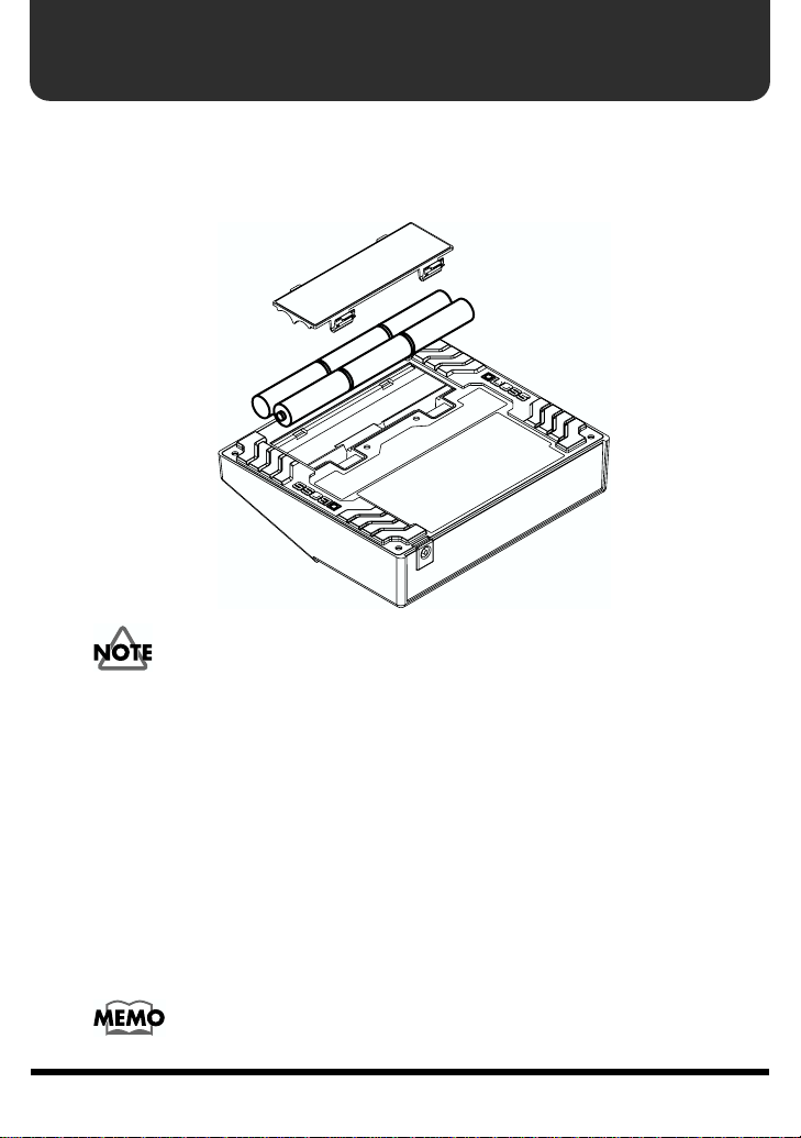
Installing Batteries
Batteries are supplied with the unit. The life of these batteries may be limited,
however, since their primary purpose was to enable testing.
Insert the included batteries as shown in figure, being careful to orient the batteries
correctly.
fig.02
• When turning the unit upside-down, get a bunch of newspapers or magazines, and
place them under the four corners or at both ends to prevent damage to the
buttons and controls. Also, you should try to orient the unit so no buttons or
controls get damaged.
• When turning the unit upside-down, handle with care to avoid dropping it, or
allowing it to fall or tip over.
• Make sure the “+” and “–” ends of the batteries are oriented correctly.
• When the batteries run down, the POWER indicator gets dim. If this happens,
replace with new batteries.
• When replacing the batteries, use six AA type.
• Avoid using new batteries together with used ones. In addition, avoid mixing
different types of batteries. Doing so can result in fluid leakage.
• Battery life can vary depending on battery type.
Continuous usage time under battery power is about 10 hours with
alkaline batteries and about 4 hours with carbon batteries. (This may
vary according to usage conditions.)
2
Page 3

Making the Connections
• The use of an AC adaptor is recommended as the unit’s power consumption is
relatively high. Should you prefer to use batteries, please use the alkaline type.
• Noise may be produced if wireless communications devices, such as cell phones,
are operated in the vicinity of this unit. Such noise could occur when receiving or
initiating a call, or while conversing. Should you experience such problems, you
should relocate such wireless devices so they are at a greater distance from this
unit, or switch them off.
• Use a cable from Roland to make the connection. If using some other make of
connection cable, please note the following precautions.
• Some connection cables contain resistors. Do not use cables that incorporate
resistors for connecting to this unit. The use of such cables can cause the sound
level to be extremely low, or impossible to hear. For information on cable
specifications, contact the manufacturer of the cable.
• When the unit is running on battery power, the power comes on when you insert
the connector plug into the INPUT R (MONO) jack.
• To prevent malfunction and/or damage to speakers or other devices, always turn
down the volume, and turn off the power on all devices before making any
connections.
• If there are batteries in the unit while an AC adaptor is being used, normal
operation will continue should the line voltage be interrupted (power blackout or
power cord disconnection).
• Once the connections have been completed, turn on power to your various devices
in the order specified. By turning on devices in the wrong order, you risk causing
malfunction and/or damage to speakers and other devices.
When powering up: Turn on the power to your guitar amp
When powering down: Turn off the power to your guitar amp
• Always make sure to have the volume level turned down before switching on
power. Even with the volume all the way down, you may still hear some sound
when the power is switched on, but this is normal, and does not indicate a
malfunction.
• When operating on battery power only, the unit’s indicator will become dim when
battery power gets too low. Replace the battery as soon as possible.
• Turn on the power before you connect headphones. When turning off the power,
first unplug the headphones, then switch off the power.
• Please observe due caution when using headphones while the LEVEL switch is set
to +4 dBu, since their volume may get significantly higher.
last
first
.
.
3
Page 4
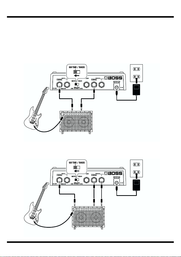
Making the Connections
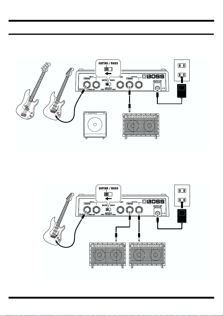
Connecting to a Guitar/Bass Amp
Monaural Connection
fig.03
or
Electric
Bass
Electric
Guitar
Stereo Connection
fig.04
Electric Guitar
(Bass Guitar)
AC Adaptor
PSA-series
(option)
or
Guitar AmplifierBass Amplifier
AC Adaptor
PSA-series
(option)
Guitar Amplifier
(Bass Amplifier)
4
Page 5
Making the Connections
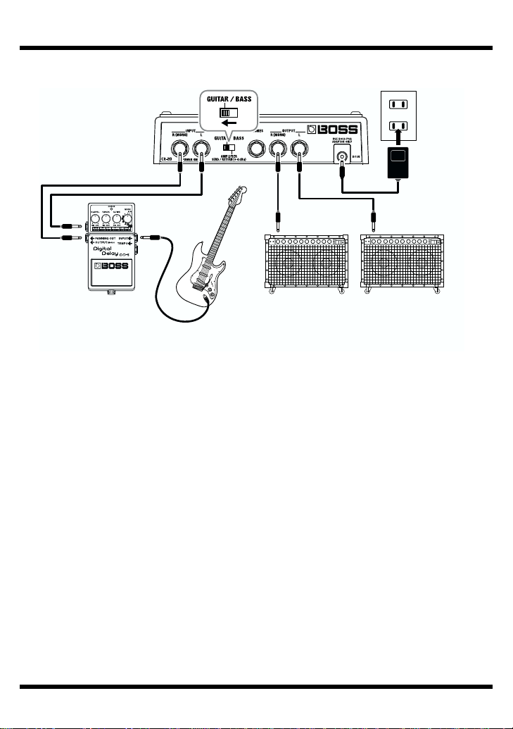
Connecting the Stereo Output and the Effects Processor
fig.05
AC Adaptor
PSA-series
(option)
Effecter
Electric Guitar
(Bass Guitar)
Guitar Amplifier
(Bass Amplifier)
5
Page 6
Making the Connections
Connecting to SEND/RETURN on the Guitar/Bass Amp
* Match the send output level on the guitar/bass amp and the level setting on the unit. If the
PEAK indicator lights up frequently, turn down the output on the guitar/bass amp.
* When the guitar/bass amp’s SEND/RETURN level is at +4 dBu, set the LEVEL switch on
the rear panel of the unit to +4 dBu.
Monaural Send/Monaural Return
fig.06
AC Adaptor
PSA-series
(option)
SEND RETURN
Electric Guitar
(Bass Guitar)
Guitar Amplifier
(Bass Amplifier)
Monaural Send/Monaural Return
fig.06a
SEND
Electric Guitar
(Bass Guitar)
6
Guitar Amplifier
(Bass Amplifier)
AC Adaptor
PSA-series
(option)
RETURN LRETURN R
Page 7
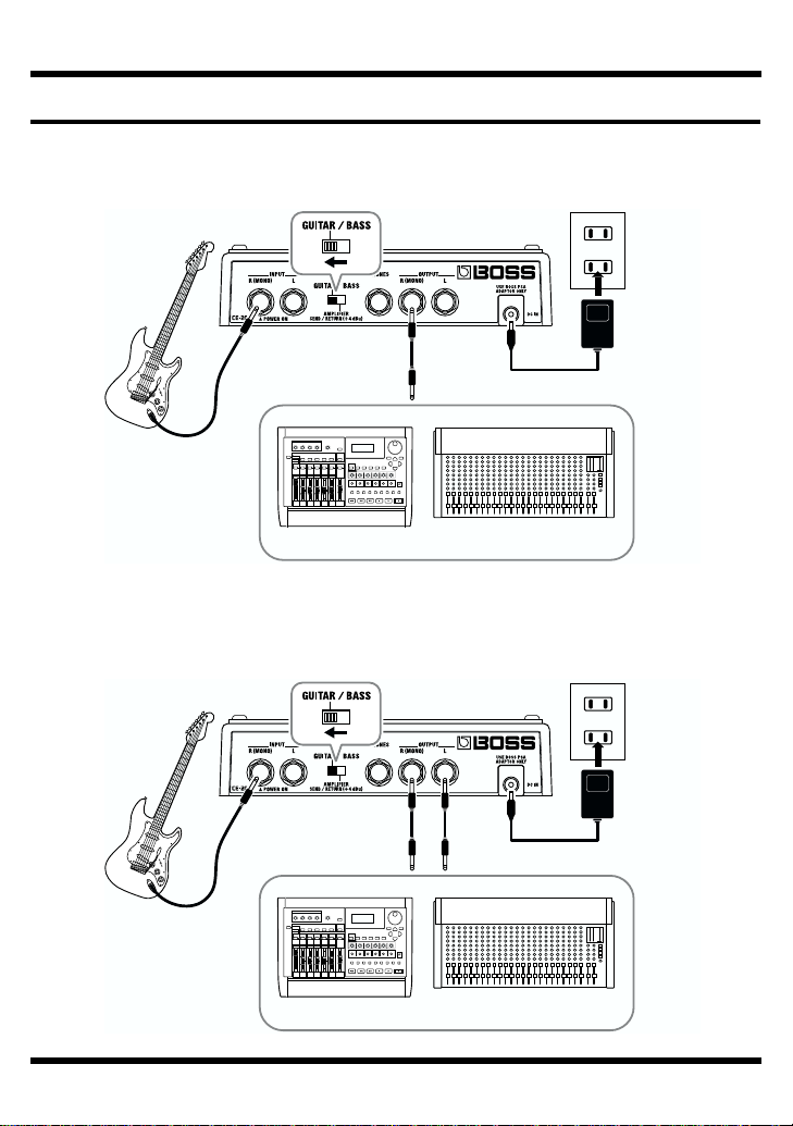
Connecting to an MTR or Mixer
Monaural Connection
fig.07
Electric Guitar
(Bass Guitar)
MixerMTR
Stereo Connection
fig.08
Making the Connections
AC Adaptor
PSA-series
(option)
Electric Guitar
(Bass Guitar)
AC Adaptor
PSA-series
(option)
MixerMTR
7
Page 8
Making the Connections
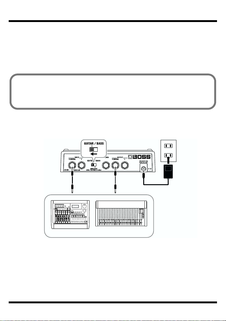
Connecting to SEND/RETURN on the MTR or Mixer
* Match the send output level on the MTR or Mixer and the level setting on the unit. If the
PEAK indicator lights up frequently, turn down the output on the MTR or Mixer.
* When the MTR or Mixer’s SEND/RETURN level is at +4 dBu, set the LEVEL switch on
the rear panel of the unit to +4 dBu.
When the CE-20 is connected to a mixer’s or multitrack recorder’s sends or
returns, you can then elect to output only the chorus sound, with the direct
sound turned off.
For more details, refer to “Switching the Direct Sound On and Off” (p. 22).
Monaural Send/Monaural Return
fig.09
AC Adaptor
PSA-series
(option)
SEND RETURN
MixerMTR
8
Page 9
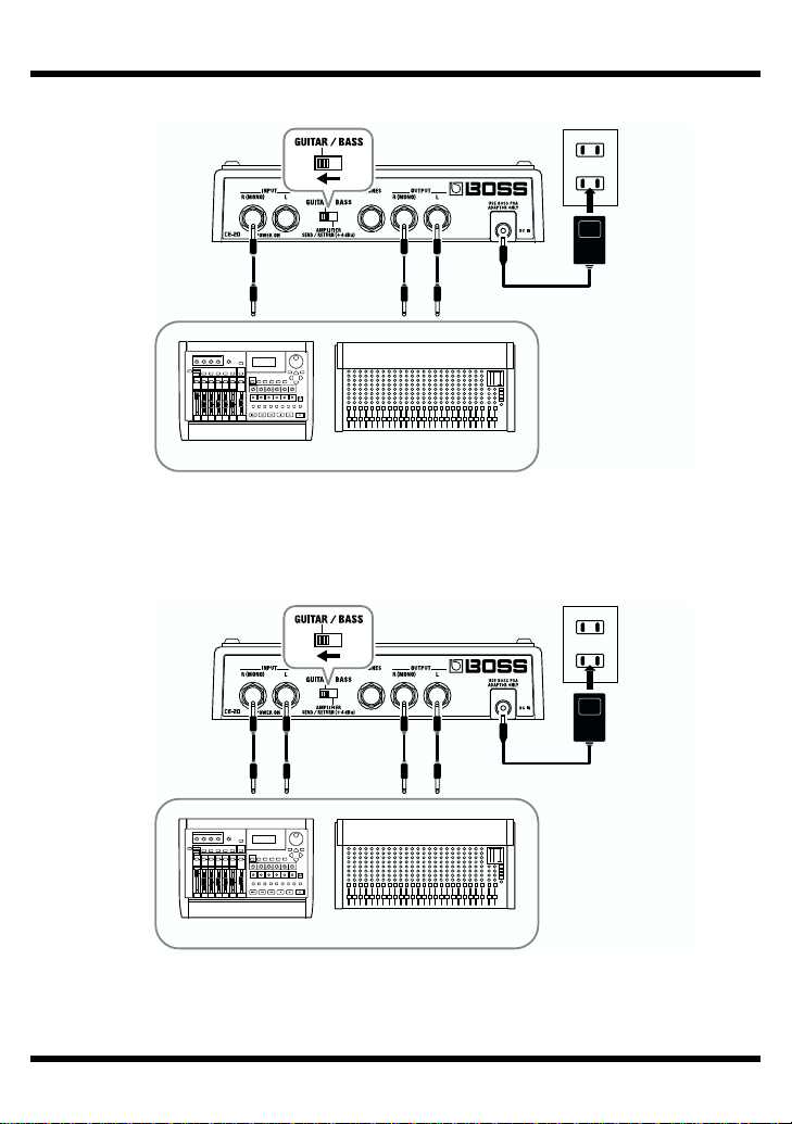
Monaural Send/Stereo Return
fig.10
SEND RETURN R RETURN L
Stereo Send/Stereo Return
fig.11
Making the Connections
AC Adaptor
PSA-series
(option)
MixerMTR
SEND R SEND L
RETURN R RETURN L
AC Adaptor
PSA-series
(option)
MixerMTR
9
Page 10
Operation
“MANUAL” is selected when the power is turned on.
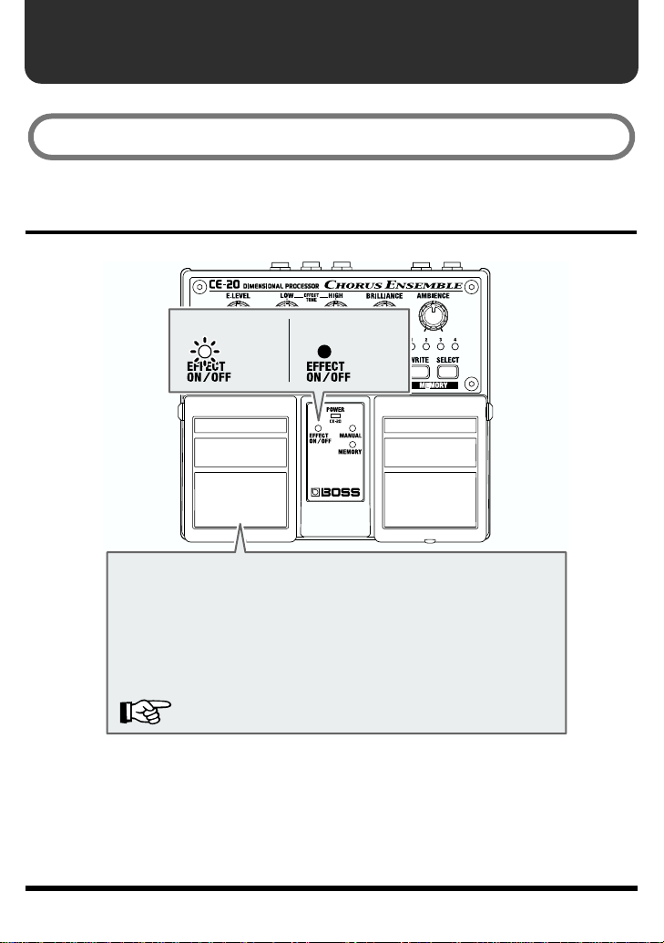
EFFECT ON/OFF Pedal Operation
fig.12
When at “ON”
←
Lit
Each press of the EFFECT ON/OFF pedal switches effects on or
off. When effects are off, the sound coming in through the INPUT
jack is output unchanged.
* When direct sound is set to OFF, no signal is output from the
OUTPUT jacks when the effects are off. When the effects are
turned on, only the effect sound is output.
The factory default setting for direct sound is ON.
“Switching the Direct Sound On and Off” (p. 22)
When at “OFF”
←
Not Lit
10
Page 11

MANUAL/MEMORY Pedal Operation
The Pedal mode (1–3) changes the function of the MANUAL/MEMORY pedal (or
the MANUAL/MEMORY pedal used with the EFFECT ON/OFF pedal). Use the
most appropriate setting for your particular application.
At the factory settings, Pedal mode is set to “1.”
When changing the Pedal mode settings, refer to p. 12.
Pedal mode: 1
Pressing the MANUAL/MEMORY pedal cycles you through a series of selections,
in this order: MANUAL → MEMORY 1 → MEMORY 2 → MEMORY 3
MEMORY 4 → MANUAL. This convenient feature makes it easier to switch
memories in which multiple memories are used.
fig.13
MEMORY 1 MEMORY 2 MEMORY 3 MEMORY 4
Pedal mode: 2
fig.14
Pressing the MANUAL/MEMORY pedal switches you
between MANUAL and the selected memory (shown by
the lit indicator). This is convenient when you want to
switch an effect sound on and off instantly.
Operation
→
MEMORY
Pedal mode: 3
fig.15
Pressing the MANUAL/MEMORY pedal toggles you
between MANUAL and the selected memory (shown by
the lit indicator).
You can also select among Memories 1–4 by pressing the MANUAL/MEMORY pedal
and EFFECT ON/OFF pedal simultaneously. This is convenient for both switching
effect sounds on and off instantly, and switching memories between songs.
fig.16
MEMORY 1 MEMORY 2 MEMORY 3 MEMORY 4
MEMORY
11
Page 12

Operation
Changing the Pedal Mode Settings
Use the following procedure when changing the Pedal mode settings.
* The pedal mode setting is stored in memory when the power is switched off.
1.
Switch off the power.
• When running on battery power:
Disconnect the connection plug from the INPUT R (MONO) jack.
• When running on power from an AC adaptor:
Disconnect the plug from the AC ADAPTOR jack.
2.
While holding down the SELECT button, switch on the power.
• When running on battery power:
Insert the connection plug into the INPUT R (MONO) jack.
• When running on power from an AC adaptor:
Insert the AC adaptor plug into the AC ADAPTOR jack.
When the button is released, the MANUAL and MEMORY indicators light up, and
the memory indicator for the current Pedal mode setting flashes.
3.
Set the pedal mode (1–3) pressing the SELECT button.
Pedal mode 1: MEMORY 1 indicator flashes.
Pedal mode 2: MEMORY 2 indicator flashes.
Pedal mode 3: MEMORY 3 indicator flashes.
4.
Press the WRITE button.
After the MEMORY Number indicator begins flashing rapidly, the setting is stored
in memory and the unit returns to its ordinary state.
* To cancel the setting change and return the unit to its ordinary state, then before you press
the WRITE button, operate the MANUAL/MEMORY or EFFECT ON/OFF pedal.
EFFECT ON/OFF Pedal
+
MANUAL/MEMORY Pedal
–
–
Selects from MEMORY 1–4
MANUAL/MEMORY Pedal
Switches
MANUAL/MEMORY 1/2/3/4
Switches MANUAL/MEMORY
Switches MANUAL/MEMORY
12
Pedal
Mode
1
2
3
EFFECT ON/OFF
Pedal
effect on/off
effect on/off
effect on/off
Page 13

Panel Operation
In order to follow along with the instructions given here, you should start out by
having effects switched ON (press the EFFECT ON/OFF pedal and confirm that
the EFFECT ON/OFF indicator has lighted), and press the MANUAL/MEMORY
pedal to switch MANUAL (MANUAL indicator has lighted).
Also set the knobs as shown in the illustration.
fig.17
76
4 5
Operation
1
1.
Select an appropriate chorus effect from the six available types.
2.
Adjust the chorus rate by rotating the RATE knob.
3.
Adjust the chorus depth by rotating the DEPTH knob.
* No function is assigned to this knob when MODE is set to “DIMENSIONAL D” or “CE-1.”
4.
Rotate the BRILLIANCE knob to adjust the amount of “glisten” in the high
end.
5.
Rotate the AMBIENCE knob to adjust the amount of body and richness in the
effect sound.
6.
Adjust the tonal qualities of the effect sound with the EFFECT TONE LOW
and HIGH knobs.
7.
Adjust the volume of the effect sound with the E.LEVEL knob.
2 3
13
Page 14

Operation
Storing Settings (Write Operation)
Storing the “MANUAL” Sound in Memory
Do not switch off the power while a write operation is in progress.
1.
Create the sound you want when set to “MANUAL.”
2.
Press the WRITE button.
The MEMORY indicator and the indicator for the currently selected memory flash,
and the CE-20 is put into write standby.
fig.19a
Write standby
Blink
3.
Press the SELECT button to select the memory (number) to which you want
to store the sound.
The indicator for the selected MEMORY number flashes.
fig.19b
BlinkBlink
Blink
14
Page 15

Operation
4.
Press the WRITE button.
The write operation is completed when the MEMORY indicator and the indicator
for the write-destination memory begin to flash more rapidly.
fig.20
Blink
Writing
Write Finished
Blink rapidly Lit
* To cancel the write operation, then before you press the WRITE button, rotate the knob or
operate the MANUAL/MEMORY pedal.
15
Page 16

Operation
Changing and Storing the “MEMORY” Sound
Do not switch off the power while a write operation is in progress.
1.
Press the MANUAL/MEMORY pedal or the SELECT button to change to the
“MEMORY” sound.
2.
Operate the knobs to change the sound.
* To avoid sudden inadvertent changes in sound, the E.LEVEL, LOW, HIGH,
BRILLIANCE, AMBIENCE, RATE, and DEPTH knobs are designed so that the setting
does not change unless the knob is first turned as far as the stored setting value. Once the
position of the knob matches the setting value stored in memory, the sound starts to change.
When a setting changes, the MEMORY indicator flashes automatically.
fig.21
Blink
3.
Press the WRITE button.
The MEMORY indicator and the indicator for the currently selected MEMORY
number start to flash, and the CE-20 is put into write standby.
fig.22
Write standby
BlinkLit
16
Blink
Page 17

4.
Press the SELECT button to select the memory (number) to which you want
to store the sound.
The indicator for the selected MEMORY number flashes.
fig.22a
BlinkBlink
5.
Press the WRITE button.
The write operation is completed when the MEMORY indicator and the indicator
for the write-destination memory begin to flash more rapidly.
fig.23
Blink
Writing Write finished
Operation
Blink rapidly
Lit
* If the knob or the MANUAL/MEMORY pedal position is changed before the WRITE
button is pressed, the write operation is cancelled, and the CE-20 is returned to the status
in effect in Step 2.
17
Page 18

Part Names and Functions
Front Panel
fig.24
LOW Knob
Adjusts the chorus sound’s lower range. At the center position,
this is flat (no boost or cut; the LOW knob has no effect).
HIGH Knob
Adjusts the chorus sound’s upper range. At the center position,
this is flat (no boost or cut; the HIGH knob has no effect).
E.LEVEL (effect level) Knob
Adjusts the volume of the effect
sound.
MODE Knob
Select the type of chorus effect.
No function is assigned to the DEPTH knob
when “DIMENSIONAL D” or “CE-1” is selected.
“MODE List” (p. 19)
BRILLIANCE Knob
Adjusts the guitar’s harmonic content
and the characteristic glistening effect
of the chorus sound.
DEPTH Knob
Adjusts the chorus depth.
* No function is assigned to this
knob when MODE is set to
“DIMENSIONAL D” or “CE-1.”
RATE Knob
Adjusts the chorus rate.
* When “DIMENSIONAL D” is selected as the MODE, this knob
provides for selection among the SDD-320's 1, 2, 3, 4, 1+4, 2+4,
and 3+4 settings.
* When MODE is set to “CE-1,” this knob functions as an INTENSITY knob, used to
adjust the amount of chorus effect.
Rate Indicator
The flashing of this indicator light changes in sync with the chorus rate set with the
RATE knob, allowing you to confirm the chorus rate at a glance.
AMBIENCE Knob
Adjusts the depth and
breadth of the effect
sound.
4
1+4
3
2
1
2+4
3+4
18
Page 19

MODE List
RICH
BASS
ACOUSTIC
STANDARD
DIMENSIONAL D
CE-1
Type
Part Names and Functions
Features
Chorus with unprecedented breadth and minimal
thinning of the sound.
Chorus specially tuned for bass that maintains the low
end. Great for that bass or heavy guitar sound.
Chorus tuned especially for acoustic guitar. Ripple is
minimized for a natural-sounding chorus effect.
General chorus sound. A perfect sound suitable for any
kind of instrument.
Models the Roland DIMENSION D (SDD-320). Provides
a clear, crisp chorus sound. With this mode selected, you
can use the RATE knob to switch between 1, 2, 3, 4, 1+4,
2+4, and 3+4 settings.
* The DEPTH knob is assigned no function in this mode.
Models that venerable classic, the BOSS “CE-1” Chorus
Effect. This effect provides a chorus sound with the CE1’s characteristic analog warmth. When the CE-1 mode is
selected, the RATE knob functions as an INTENSITY
knob, allowing you to adjust the amount of chorus effect
applied.
* The DEPTH knob is assigned no function in this mode.
19
Page 20

Part Names and Functions
fig.25
PEAK Indicator
This lights up when the signal is at before cliping.
If the PEAK indicator lights up frequently, turn down
the E.LEVEL knob. Also check the LOW, HIGH,
BRILLIANCE, and AMBIENCE knob settings; if
raised, try reducing these settings. If in spite of
these measures the PEAK indicator continues to
light up, lower the output level of the device
connected to the INPUT jacks or set the LEVEL
switch to +4 dBu.
POWER Indicator
This lights up when the
power is on.
EFFECT ON/OFF
Indicator
This lights up when
effects are on.
EFFECT ON/OFF Pedal
Each press of the pedal switches the
effects on or off.
MANUAL Indicator
This lights up when set to “MANUAL.”
MEMORY Indicator
This lights up when set to “MEMORY.”
When “MEMORY” is selected, the indicator flashes
whenever knob setting values are changed or when
the CE-20 is in write standby; the indicator flashes
more rapidly while the write operation is in progress.
When at “MANUAL” When at “MANUAL”
←
Lit
←
Not Lit
←
←
Not Lit
Lit
MEMORY Number Indicator
(1–4)
The indicator for the currently selected
MEMORY number (1–4) lights.
The indicator flashes while the CE-20 is
in write standby; the indicator flashes
more rapidly while the write operation is
in progress.
SELECT Button
This changes the
memory 1–4.
WRITE Button
Press this to store
settings in
“MEMORY.”
MANUAL/MEMORY Pedal
Select the unit between “MANUAL,”
which produces the sound of the panel
knob settings unchanged, and
“MEMORY,” where settings have been
stored in advance.
Functions differ according to the Pedal
mode settings; make the most
appropriate setting for your particular
application.
“MANUAL/MEMORY Pedal
Operation” (p. 11)
20
Page 21

Rear Panel
fig.26
INPUT Jacks (R (MONO), L)
This is the input jack for connecting to the
output of an electric guitar or other instrument
or effects processor.
For monaural use, make the connection to the
R (MONO) jack.
“Making the Connections” (p. 3–9)
* The INPUT R (MONO) jack also doubles as
the power switch when the unit is running
on battery power. The power comes on
when a plug is inserted into the INPUT R
(MONO) jack, and goes off when it is
unplugged. Unplug any connected cords
when the unit is not in use.
Part Names and Functions
PHONES Jack
You can connect headphones here to monitor
the sound.
* Turn on the power before you connect
headphones. When turning off the power,
first unplug the headphones, then switch off
the power.
* Please observe due caution when using
headphones while the LEVEL switch is set to
+4 dBu, since their volume may get
significantly higher.
AC Adaptor Jack
This jack is for connecting an AC
adaptor (BOSS PSA-series, sold
separately). Using an AC adaptor
makes possible long performances with
no worry about batteries going dead.
LEVEL Switch
This switch sets the input level to correspond to the
device connected to the INPUT jacks.
GUITAR/BASS:
When using an electric guitar or bass guitar.
AMPLIFIER, SEND/RETURN:
When connected to send or return on a guitar
amp or the like, or when connected to a largevolume output device
“Making the Connections” (p. 3–9)
OUTPUT Jacks (R (MONO), L)
This jack is for connection to a
guitar/bass amp, another effects
processor, mixer, MTR, or the like.
For monaural use, make the connection
to the R (MONO) jack.
“Making the Connections”
(p. 3–9)
21
Page 22

Switching the Direct Sound On and Off
When the CE-20 is connected to a mixer’s or multitrack recorder’s sends or returns,
you can then elect to output only the chorus sound, with the direct sound turned
off.
Use the following steps to turn the direct sound on and off.
1.
Switch off the power.
• When running on battery power:
Disconnect the connection plug from the INPUT R (MONO) jack.
• When running on power from an AC adaptor:
Disconnect the plug from the AC ADAPTOR jack.
2.
While holding down the EFFECT ON/OFF pedal, switch on the power.
• When running on battery power:
Insert the connection plug into the INPUT R (MONO) jack.
• When running on power from an AC adaptor:
Insert the AC adaptor plug into the AC ADAPTOR jack.
When the pedal is released, the MEMORY number indicators 1 and 2 flash.
3.
Press the EFFECT ON/OFF pedal to set the direct sound to ON or OFF.
EFFECT ON/OFF indicator lit: direct sound is output.
EFFECT ON/OFF indicator off: direct sound is not output.
4.
Press the WRITE button.
After the MEMORY number indicators 1 and 2 begin flashing rapidly, the setting is
stored in memory and the unit returns to its ordinary state.
* To cancel the setting change and the unit returns to its ordinary state, then before you
press the WRITE button, operate the MANUAL/MEMORY pedal.
22
Page 23

Changing How Memory Numbers Are Indicated
Not only can you confirm the currently selected memory merely by checking the lit
MEMORY number indicators, you can also change the pattern in which the
indicators light up. Select the pattern that provides the easiest way to check the
memory in any particular environment.
When using the CE-20 in dimly lit surroundings, you can confirm
memory numbers more easily by using the Lighting Pattern 2 setting.
Lighting Pattern 1 (Normal):
Only the indicator for the selected memory lights up (or flashes).
Lighting Pattern 2:
The number of indicators lighting up (or flashing) corresponds to the selected
memory number.
When MEMORY 1 is selected: Indicator 1 lights up.
When MEMORY 2 is selected: Indicators 1 and 2 light up.
When MEMORY 3 is selected: Indicators 1, 2, and 3 light up.
When MEMORY 4 is selected: Indicators 1, 2, 3, and 4 light up.
You can select the indicator lighting pattern by means of the following procedure.
1.
Switch off the power.
• When running on battery power:
Disconnect the connection plug from the INPUT R (MONO) jack.
• When running on power from an AC adaptor:
Disconnect the plug from the AC ADAPTOR jack.
2.
While holding down the WRITE button and the SELECT button, switch on the power.
• When running on battery power:
Insert the connection plug into the INPUT R (MONO) jack.
• When running on power from an AC adaptor:
Insert the AC adaptor plug into the AC ADAPTOR jack.
When the button is released, the MANUAL indicator flashes, and either indicator
no. 1 alone, or all of the indicators from 1 through 4 flash.
3. Press the MEMORY SELECT button to set the MEMORY indicator lighting pattern.
Lighting Pattern 1: Indicator 1 alone lights.
Lighting Pattern 2: Indicators 1–4 all light.
4. Press the WRITE button.
After the MEMORY Number indicator begins flashing rapidly, the setting is stored
in memory and the unit returns to its ordinary state.
* To cancel the setting change and the unit returns to its ordinary state, then before you
press the WRITE button, operate the MANUAL/MEMORY or EFFECT ON/OFF pedal.
23
Page 24

Returning Settings to Their Factory Defaults
You can restore the memories (1–4), pedal mode settings, and the direct sound
mute settings to their original factory values.
Memory 1 (p. 26) SUPER RICH
Memory Settings
Pedal Mode (p. 11–12) 1
Direct Sound ON/OFF (p. 22) ON
MEMORY Number Indication (p. 23) Lighting Pattern 1
Carrying out the following procedure completely clears the content
currently stored in the memories (1–4).
1. Switch off the power.
• When running on battery power:
Disconnect the connection plug from the INPUT R (MONO) jack.
• When running on power from an AC adaptor:
Disconnect the plug from the AC ADAPTOR jack.
2. While holding down the WRITE button, switch on the power.
• When running on battery power:
Insert the connection plug into the INPUT R (MONO) jack.
• When running on power from an AC adaptor:
Insert the AC adaptor plug into the AC ADAPTOR jack.
Memory 2 (p. 26) BASS STANDARD
Memory 3 (p. 27) DEEP CHORUS
Memory 4 (p. 28) CE-1
When you release the button, the MEMORY Number indicators (1–4) flash.
3. Press the WRITE button.
After the MEMORY Number indicators (1–4) begin flashing rapidly, the setting is
stored in memory and the unit returns to its ordinary state.
* To cancel the setting change and the unit returns to its ordinary state, then before you
press the WRITE button, operate the MANUAL/MEMORY or EFFECT ON/OFF pedal.
24
Page 25

Troubleshooting
The power doesn’t come on.
❍ Is the guitar connected correctly to the
INPUT R (MONO) jack?
→ Check the connections again (p. 3–9).
* When running off batteries, the unit won’t
switch on unless there’s something plugged
into the INPUT jack. This helps conserve the
batteries.
❍
Is the plug connected to the INPUT L jack?
→ When using battery power, connect the
plug to the INPUT R (MONO) jack.
❍ Have the batteries run down?
→ Replace with fresh batteries (p. 2).
❍ Is the specified AC adaptor (PSA-series
sold separately) connected correctly?
→ Check the connections again (p. 3–9).
There is no sound/volume
is too low.
❍
Is the other equipment connected correctly?
→ Check the connections again (p. 3–9).
❍ Is the volume turned down on the
connected guitar/bass amp, effects
processor, or other device?
→ Check the settings on the connected
equipment (p. 3–9).
❍ Is the LEVEL switch on the rear panel set
correctly?
→ Set the LEVEL switch to match the
connected equipment (p. 3–9).
❍ Is the direct sound ON/OFF set to OFF?
→ Only the effect sound is output when this is
set to OFF. When you want to output the
direct sound as well, set this to ON (p. 22).
❍ Is the effect level set to minimum?
→ Operate the E.LEVEL knob to adjust the
effect level.
Sound is distorted.
❍ Are the EFFECT TONE (LOW/HIGH),
BRILLIANCE, and AMBIENCE knobs
positioned correctly?
→ Sounds may become distorted with the
knobs at certain settings. Turn down one or
more of these knobs, or turn down the
E.LEVEL knob until the PEAK indicator
does not light up too frequently. If in spite
of these measures the sound is still
distorted, lower the output level of the
device connected to the INPUT jacks, or set
the LEVEL switch to AMPLIFIER SEND/
RETURN (+4 dBu).
Is the LEVEL switch set to GUITAR/BASS?
❍
→
When connecting to guitar amps, bass amps,
or other such gear, or when connecting to
equipment that outputs sound at high
volumes, set the LEVEL switch to
AMPLIFIER SEND/RETURN (+4 dBu).
Pressing the MEMORY/MANUAL
pedal does not call up the
intended memory.
❍ Is the proper Pedal mode set for your
current application?
→ The MANUAL/MEMORY pedal (or the
MANUAL/MEMORY pedal when pressed
simultaneously with EFFECT ON/OFF
pedal) functions differently according to the
Pedal mode settings. Use the most
appropriate setting for your particular
application (p. 11–12).
The volume level of the
instrument connected to INPUT
jack is too low.
❍ Could you be using a connection cable
that contains a resistor?
→ Use a connection cable that does not
contain a resistor.
25
Page 26

Sample Settings
RICH
fig.27
SUPER RICH (Memory 1)
fig.28
BASS STANDARD (Memory 2)
fig.29
26
Page 27

CHORUS FOR HEAVY RIFF
fig.30
ACOUSTIC STANDARD
fig.31
Sample Settings
DEEP CHORUS (Memory 3)
fig.31
27
Page 28

Sample Settings
STANDARD ANALOG
fig.33
DIMENSIONAL D
Roland DIMENSION D (SDD-320) Modeling Sound
fig.34
When “DIMENSIONAL D” is
selected as the MODE, the
RATE knob provides for
selection among
the SDD-320’s
1, 2, 3, 4,
1+4, 2+4, and
3+4 settings.
4
3 1+4
2
1
3+4
2+4
CE-1 (Memory 4)
BOSS CHORUS ENSEMBLE (CE-1) Modeling Sound
fig.35
28
Page 29

Setting Memo
( )
fig.36
( )
fig.36
fig.36
( )
29
Page 30

Specifications
CE-20: Dimensional Processor
Nominal Input Level
-20 dBu (GUITAR/BASS)
+4 dBu (AMPLIFIER SEND/RETURN)
Input Impedance
1 MΩ
Nominal Output Level
-20 dBu (GUITAR/BASS)
+4 dBu (AMPLIFIER SEND/RETURN)
Output Impedance
1 kΩ (OUTPUT R (MONO), L)
33 Ω (PHONES)
Recommended Load Impedance
10 kΩ
Residual Noise Level
-93 dBu or less (IHF-A typ.)
Controls
EFFECT ON/OFF Pedal
MANUAL/MEMORY Pedal
E.LEVEL Knob
LOW Knob
HIGH Knob
BRILLIANCE Knob
AMBIENCE Knob
MODE Knob
RATE Knob
DEPTH Knob
MEMORY WRITE Button
MEMORY SELECT Button
LEVEL Switch
Indicators
RPOWER Indicator
(serves also as battery check indicator)
EFFECT ON/OFF Indicator
MANAUL Indicator
MEMORY Indicator
PEAK Indicator
RATE Indicator
MEMORY Number Indicator 1–4
Connectors
INPUT Jacks (R (MONO), L)
(1/4 inch phone type)
PHONES Jack (stereo 1/4 inch phone type)
OUTPUT Jacks (R (MONO), L)
(1/4 inch phone type)
AC Adaptor Jack
Power
Dry battery (R6/LR6 (AA) type) x 6: DC 9V
AC Adaptor (DC 9V)
Current draw
160 mA (9 V max.)
* Expected battery life under continuous use:
Carbon: 4 hours
Alkaline: 10 hours
These figures will vary depending on the
actual conditions of use.
Dimensions
173 (W) x 158 (D) x 57 (H) mm
6-13/16 (W) x 6-1/4 (D) x 2-1/4 (H) inches
Weight
1.1 kg / 2 lbs 7 oz (including batteries)
Accessories
Owner’s Manual
Leaflet (“USING THE UNIT SAFELY,”
“IMPORTANT NOTES,” and “Information”)
Dry battery (LR6 (AA) type) x 6
* We recommend that alkaline batteries be used
when replacing the batteries.
Options
AC Adaptor (PSA-series)
* 0 dBu = 0.775 Vrms
* In the interest of product improvement, the
specifications and/or appearance of this unit
are subject to change without prior notice.
30
Page 31

For EU Countries
This product complies with the requirements of European Directive 89/336/EEC.
For the USA
FEDERAL COMMUNICATIONS COMMISSION
RADIO FREQUENCY INTERFERENCE STATEMENT
This equipment has been tested and found to comply with the limits for a Class B digital device, pursuant to Part 15 of the
FCC Rules. These limits are designed to provide reasonable protection against harmful interference in a residential
installation. This equipment generates, uses, and can radiate radio frequency energy and, if not installed and used in
accordance with the instructions, may cause harmful interference to radio communications. However, there is no guarantee
that interference will not occur in a particular installation. If this equipment does cause harmful interference to radio or
television reception, which can be determined by turning the equipment off and on, the user is encouraged to try to correct the
interference by one or more of the following measures:
– Reorient or relocate the receiving antenna.
– Increase the separation between the equipment and receiver.
– Connect the equipment into an outlet on a circuit different from that to which the receiver is connected.
– Consult the dealer or an experienced radio/TV technician for help.
This device complies with Part 15 of the FCC Rules. Operation is subject to the following two conditions:
(1) This device may not cause harmful interference, and
(2) This device must accept any interference received, including interference that may cause undesired operation.
Unauthorized changes or modification to this system can void the users authority to operate this equipment.
This equipment requires shielded interface cables in order to meet FCC class B Limit.
For Canada
NOTICE
This Class B digital apparatus meets all requirements of the Canadian Interference-Causing Equipment Regulations.
Cet appareil numérique de la classe B respecte toutes les exigences du Règlement sur le matériel brouilleur du Canada.
AVIS
Page 32

G6017306 ’00-xx-xx-xxx
 Loading...