

Page 1

Xerxes 20 Plus
User Guide
ANALOGUE
1
Page 2
Page 3
About Roksan
Since 1985, Roksan’s mission has been to inspire
music lovers with our world-class audio products.
Roksan immediately found global recognition with
the Xerxes Turntable. Since then, our passion for
developing award-winning audio products has
broadened into ampliers, CD players and DACs.
With British design and manufacture, Roksan ensures
outstanding build quality and reliability. Implementing
unique approaches, ground-breaking technology and
audiophile-grade components that will elevate your
audio experience to the next level and beyond.
Our enthusiasm, knowledge and expertise
is infused in everything we do.
Roksan is a member of
1
Page 4

INTRODUCTION
Congratulations on your purchase of the Roksan Xerxes 20 Plus Turntable. This Turntable is designed and
manufactured to the highest specication and rigorously tested to offer you many years of trouble-free pleasure.
Your Xerxes 20 Plus Turntable is at the heart of your record playing system and the link between the Tonearm/
Cartridge and the record. Its correct installation, setup and operation will have a profound inuence on the sonic
performance of the entire record playing system.
Please read the contents of this manual thoroughly. It will help you to understand your Xerxes 20 Plus Turntable
better and enhance your musical experience.
This manual is divided into the following sections:
• Introduction
• Unpacking
• Caution
• Design
• Setup Summary
• Setup Diagrams
• Installation
• Operation
• Troubleshooting
• Guarantee
• Specications
• Notes
Unpacking
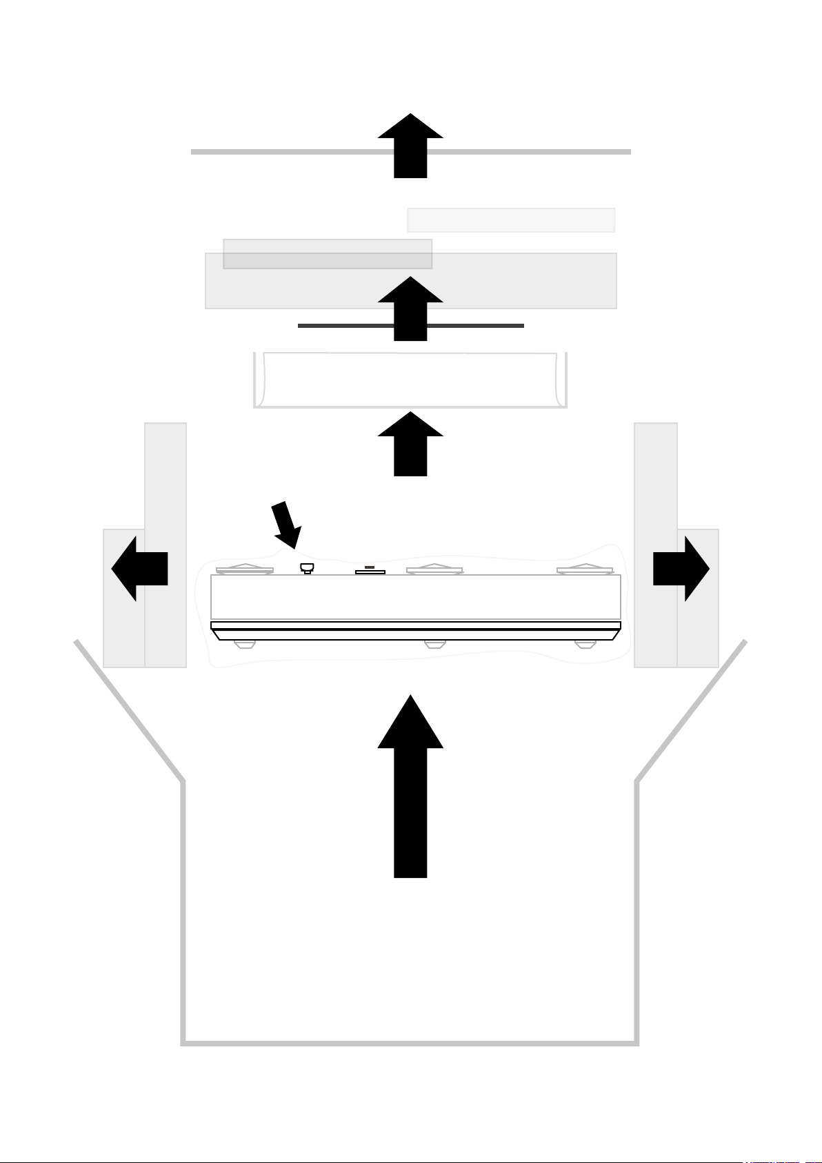
Included in the packing of your Xerxes 20 Plus Turntable you will nd:
• One Xerxes 20 Plus Inner Platter
• One Xerxes 20 Plus Outer Platter
• One Xerxes 20 Plus Drive Belt
• One Xerxes 20 Plus Spindle Cap
• One Vial of Xerxes 20 Plus Oil, Cotton Buds and Lint free tissue
• One pair of Cotton Gloves
• One Xerxes 20 Plus Dust Cover
• Set of Allen Keys (2.5, 3.0 & 5.0mm A/F)
After removing these items please retain all packing materials.
Correct packing is necessary for future transportation of your Xerxes 20 Plus Turntable.
Maintenance
First switch the amplier off and place the stylus guard on; the Turntable may then be cleaned
with a lightly dampened soft cloth or a soft brush. Be extra careful if the Cartridge has no stylus guard.
Avoid using abrasives or solvents.
*** Take care not to damage the Cartridge stylus or the Tonearm.
• The Main Bearing requires recharging with oil every 12-18 months.
• The Drive Belt requires cleaning with a wax based furniture polish every 12-18 months.
2 All specications are liable to change without notice. E&OE
Page 5
UNPACKING
Accessories
Rmat-7
Careful not to
damage the pulley
3
Page 6

CAUTION
The Xerxes 20 Plus Turntable incorporates several unique design features and manufacturing techniques.
It is important to observe the following to avoid any damage and to ensure optimum performance.
IMPORTANT
DO NOT attempt to run the Turntable without Main Bearing Oil
Careful when placing the Inner Platter
Careful when placing the Outer Platter onto the Inner Platter
(Outer Platter should not hit the Motor Pulley or drop onto the Inner Platter)
DESIGN
The Structure
It is important to observe the following to avoid any damage and to ensure optimum performance.
As with the original TMS turntable design, the Xerxes 20 Plus Turntable has three separate plinths used
for decoupling across a selective frequency band.
The Sub-plinth which carries the Main Bearing/Platter Assembly and the Tonearm is designed as a reference
platform to preserve the record/Cartridge interface from unwanted disturbances. It has been computer modelled
using nite element analysis to determine the optimum shape and of coupling of this platform to the Bottom plinth.
The Top plinth features the familiar cut-out, which was rst seen on the original Xerxes, that follows the contour
of the Sub-plinth without touching. The Top plinth is connected to the Bottom plinth via three suspension mounts.
The Bottom plinth supports, decouples and isolates the Top and the Sub-plinths from external disturbances.
The Motor is free to pivot on its own bearing on an axis of rotation coincident with the shaft of the Motor.
With this unique dynamic system transient speed changes are absorbed and do not affect the measuring platform.
The Armboard, which provides another level of isolation, is machined from a billet of Acetal with complimentary
damping between the Tonearm and the Sub-plinth. The detachable Armboard is xed by three stainless steel bolts
for easy Tonearm mounting and adjustment.
The Bearing / Platter Assembly
At the heart of Xerxes 20 Plus Turntable is Roksan’s unique and formidable self centring, self aligning true single
point Main Bearing. The innovative design of this bearing provides almost silent, frictionless rotation, precisely
dening the rotational axis. The Bearing sleeve is gun-drilled from solid phosphor bronze and honed to provide
Spindle/Bearing sleeve gap of 2/10,000” along its length! The only contact is between the polished Spindle tip
and the captive TMS 3 Tungsten Carbide super precision ball.
The Spindle is made from hardened steel and is ground with a taper that locates into the Inner Platter without the
use of adhesive or the need for pressing.
4 All specications are liable to change without notice. E&OE
Page 7
DESIGN
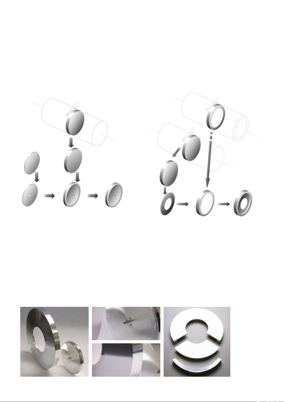
The Inner and Outer Platters are both machined from solid aluminium alloy instead of normal castings to
ensure the material is homogeneous. Each complete platter is constructed of two parts that are ‘friction’
tted together. Each part is designed as a tuning fork and hence it’s free from any nonlinearity. Their natural
frequencies are linearly damped, as these two parts are joined together by friction only. The platters are
machined to extremely high tolerances to ensure roundness and balance. Required inertia for a smooth
and constant angular speed is achieved through high peripheral distribution of mass. This maximizes inertia
to mass ratio and reduces undue pressure on the bearing contact point. It is this level of attention to detail
throughout the design that ensures musical integrity.
Inner Platter
1A Saw cut from 6
2A Precision machined to shape (Tuned resonance)
3B Cut from 16 SWG Aluminum alloy plate
4B Precision machined to shape (Tuned resonance)
5 Plate press tted on centre boss and its surface and
edge precision machined for nal size and accuracy
6 Complete Inner Platter linearly damped free of any
unwanted resonance
1/2
” solid Aluminum alloy bar
Outer Platter
1A Saw cut from 12” solid Aluminum alloy bar
2A Precision machined to shape (Tuned resonance)
3B Cut from 12” Solid Aluminum alloy plate
4B Precision machined to shape (Tuned resonance)
5 Rim heated to expand and centre part tted when
cooled the Outer Platter precision machined for
nal size and accuracy
6 Complete Outer Platter linearly damped free of
any unwanted resonance
5
Page 8
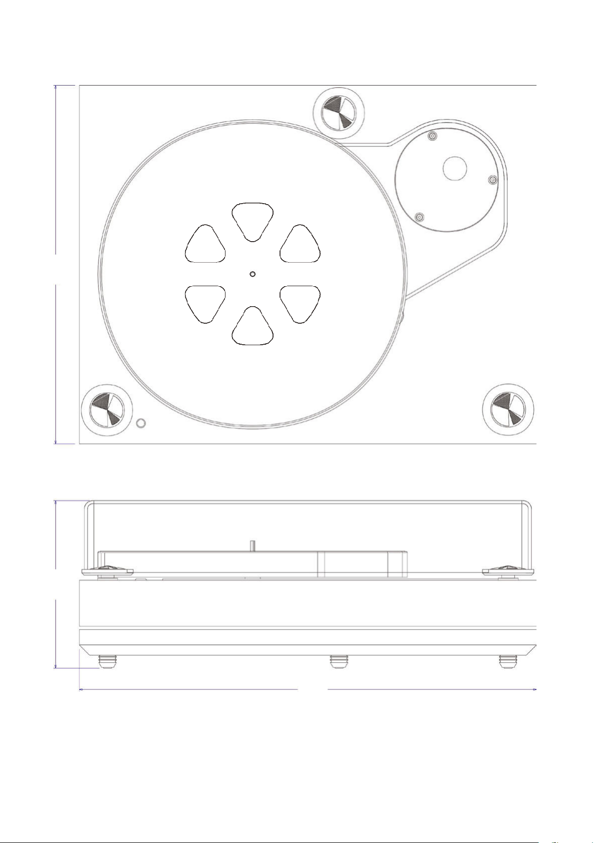
DESIGN
349mm163mm
6 All specications are liable to change without notice. E&OE
445mm
Page 9

SETUP SUMMARY
Placing the Xerxes 20 Plus Turntable
Prepare a level surface, using a spirit level, on which to place the Xerxes 20 Plus Turntable (‘absolute’ level is not
critical as long as the surface is reasonably level). If you wish to use a dedicated equipment support, ensure that
you get a ‘vertically’ rigid table. For best results it should sit rigid and level on a solid oor. For the wall mounted
turntable support, ensure the same.
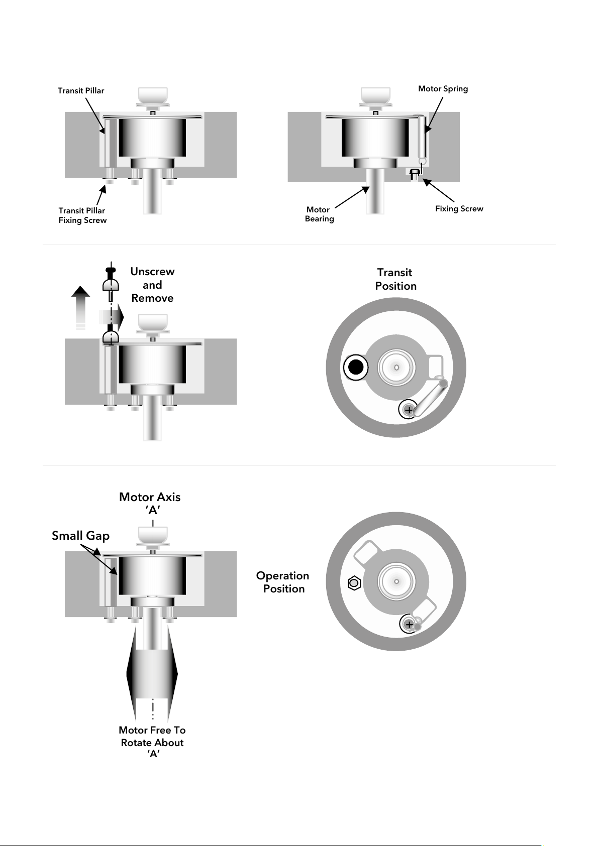
Removing the Motor Transit Screw
This screw prevents the precision Motor and its Bearing mount assembly from being damaged in transit. Undo and
remove this screw from the Transit Pillar to release the Motor Body. With the screw in place the motor spring is in
tension so be careful as the Motor will rotate back to its normal operating position. Please keep the Motor Transit
Screw safe in the packaging for future use.
Preparing the Main Bearing
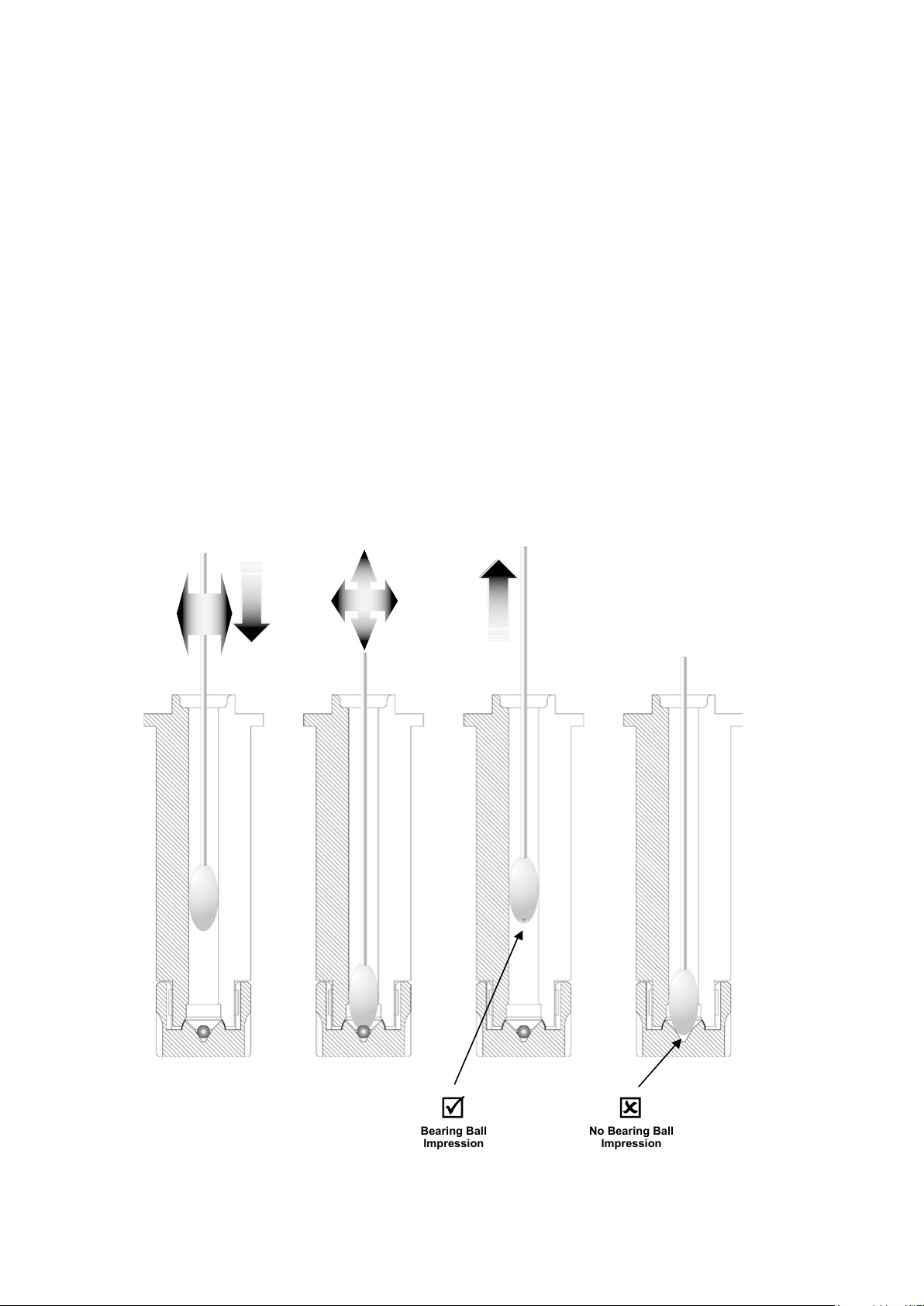
Remove the rubber plug on the Main Bearing. Push a cotton Q-tip down to the bottom of the housing and rotate
it while gently pressing down. Keep turning as you pull it out. The Cotton Bud should now have a recess in its tip,
which shows that the precision ball bearing is correctly positioned at the bottom of the housing (See gure). From
the small vial of oil, pour 4 to 5 drops of oil into the Bearing Housing. Always replace the plug, to keep the Bearing
housing clean, if you are not tting the Inner Platter immediately.
IMPORTANT: Always use Roksan supplied Main Bearing Oil
Placing the Inner Platter
Remove the Inner Platter/Spindle assembly from its plastic bag. The Spindle is slightly oiled to protect the tool steel
spindle (remember to do the same if you are storing your Xerxes 20 Plus Turntable for a length of time).
Wipe the oil from the Spindle using a soft lint-free tissue.
Remove the plug from the Bearing and carefully guide the Spindle into the Main Bearing hole. Gently spin the Inner
Platter. The platter will slowly sink over a period of about ten to twenty minutes. Do not force the platter down. The
Spindle is factory tted to ensure that the Inner Platter runs true. Take extra care not to knock or bend the Spindle.
You can check that the Inner Platter has settled by gently raising and lowering the Spindle by about 3mm. You
should hear a quiet metallic click as it touches the ball bearing. If there is enough oil a ridge will be visible at the
top of the Bearing Housing.
If you do not see a ridge, use one more drop of oil.
Fitting the Drive Belt
The Drive Belt should be wiped with a non-alcohol, wax based polish (i.e. aerosol type such as Pledge) before
tting. When this has been done, the Drive Belt can then be tted around the Inner Platter and Motor Pulley. Turn
the Inner Platter by hand for a few revolutions and the Drive Belt will come to rest in its correct operation position.
7
Page 10

SETUP SUMMARY
Fitting the Tonearm
You will need to follow the Tonearm manufacturer’s instructions as most Tonearms differ slightly in their methods of xing.
Connecting the Tonearm Cable
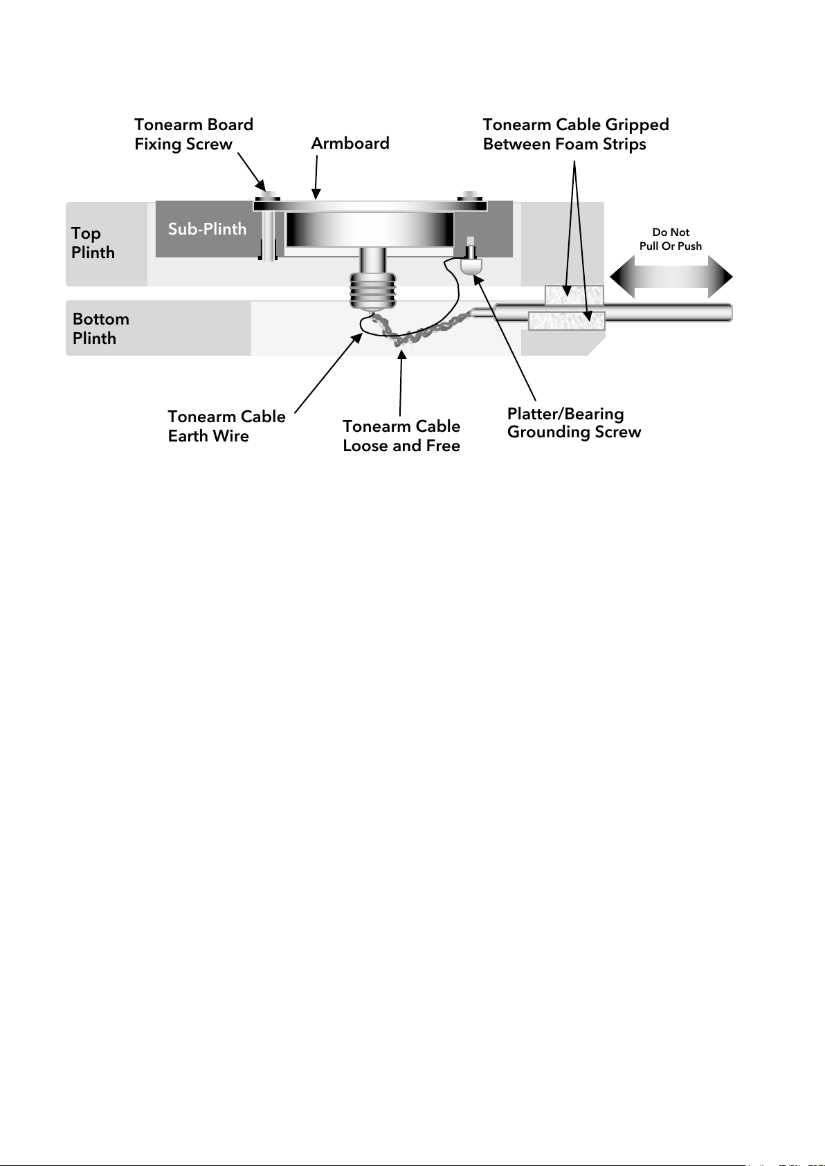
Use a standard type Tonearm Cable preferably the Roksan 5-pin Din High Denition Tonearm Cable. This must either
be ‘freely’ dressed in between the foam strips or xed securely to the Bottom plinth using cable ties (See gure). It is
important that the Tonearm Cable is ‘loose/free’ between the Tonearm and plinth (The foam strips or the cable-ties).
Otherwise this will restrict the movement of the Sub-plinth/Armboard and interfere with the decoupling/isolation of
Xerxes 20 Plus Turntable.
Fitting the Outer Platter
Remove the Outer Platter from its plastic bag. Gently place the Outer Platter on the Inner Platter; the recess on the inside
locates onto the plate of the Inner Platter. Take care not to hit the Motor Pulley with the rim of the Outer Platter.
Fitting the Rmat-7
The Xerxes 20 Plus Turntable is supplied with the Roksan Rmat-7 which is designed to provide optimum contact between
the record and the platter assembly. It ts over the Main Bearing Spindle in the centre and rests uniformly over the platter
surface. Use the Rmat-7 retaining ‘O’ ring and gently push it onto the Spindle to secure the Rmat-7. This will stop the
Rmat-7 ‘sticking’ to the record while changing record/sides.
The Centre Piece (Spindle Cap)
Roksan introduced this unique removable Centre Piece with the original Xerxes. Slide the Centre Piece over the Bearing
Spindle to assist placing the record centrally on the Rmat-7. Before playing the record, the Centre Piece can be removed
to eliminate any direct mechanical contact between the record and the Main Bearing Spindle. The only contact would be
through the Rmat-7 and the stylus. *** DO NOT USE RECORD CLAMPS ***
IMPORTANT: Use of any clamp directly connects the record to the structure and allows unwanted ‘noise’ to be
immediately present in the record and thus ‘picked up’ by the Cartridge.
Do not use any record weights as this may permanently damage the Main Bearing.
Connecting the Power Supply
The dedicated Turntable power supply is connected to the rear of the Turntable using the 5 pin connector.
Always connect the power supplies before switching it on.
Operation
Switch on the dedicated Xerxes Power Supply and choose the desired speed. The platter should start turning. Place the
record on the Rmat-7 ensuring the Centre Piece is in place. When the record is on the platter remove the Centre Piece
and place it in Spindle cap rest on the Top plinth.
8 All specications are liable to change without notice. E&OE
Page 11
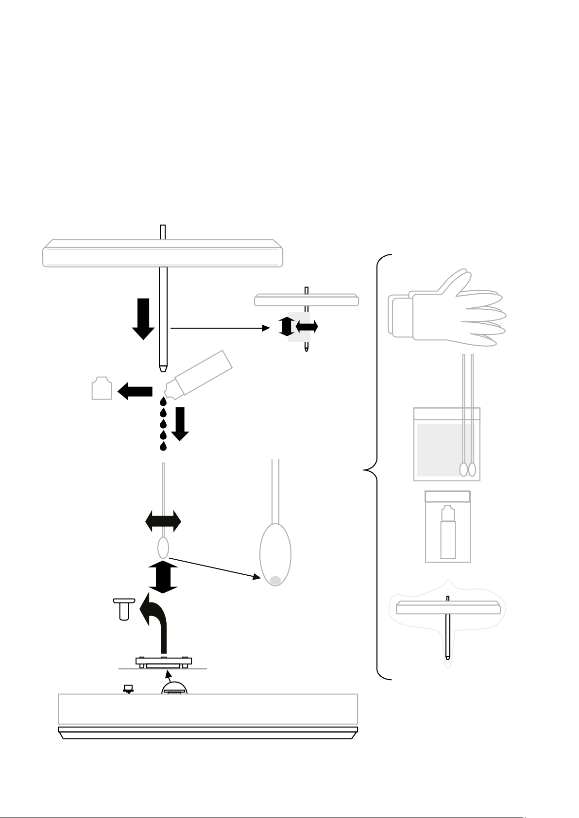
SETUP DIAGRAMS
Fitting the Inner Platter
1 Pull out the Main Bearing Plug and place it in the Oil Vial bag
2 Carefully clean the Main Bearing with one of the Cotton Buds and check that there is a ball impression on the tip
3 Remove the Oil Vial cap and charge the Main Bearing with 4 to 5 drops of Roksan supplied oil
4 Wear the Cotton Gloves and remove the Inner Platter from its bag: use the Lint free tissue and gently clean the
Inner Platter Spindle free from any dirt
5 Gently place the Inner Platter Spindle into the Main Bearing and allow it to settle down *
* Due to very tight tolerances the Inner Platter will take some time to settle down
5.
4.
3.
2.
1.
9
Page 12
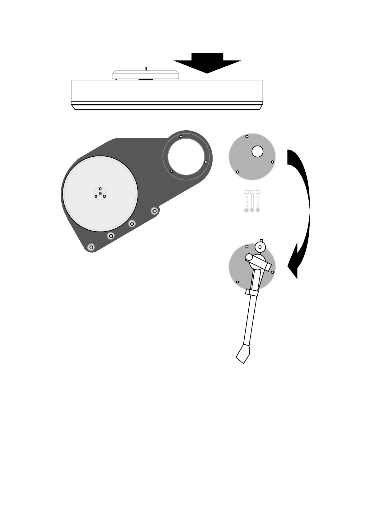
SETUP DIAGRAMS
Fitting Tonearm and Phono Cartridge
1 Use the 3mm A/F Allen key and remove the Acetal Armboard
2 Carefully x the Phono Cartridge to the Headshell following manufacturer’s instructions
3 Carefully mount the Tonearm to the Armboard following manufacturer’s instructions
(do not fully tighten the Tonearm to the Armboard allowing for later adjustments)
4 Remount Armboard tightening the Allen bolts fully (if required support the Armboard from
underneath while tightening the bolts)
5 Plug in the Tonarm Cable connector and check that the Sub-plinth assembly is free
6 Ensure the gap around the Sub-plinth is even (if necessary gently lift the Sub-plinth and reposition it)
IMPORTANT NOTE
The Xerxes 20 Plus Turntable Sub-plinth alignment is factory set according to the cut out on the
Tonearm board (e.g. Artemiz cut is set for the Artemiz Tonearm weight etc.). If the Tonearm to be
tted is heavier or lighter than the one anticipated, then the Sub-plinth may require readjustment.
10 All specications are liable to change without notice. E&OE
Page 13
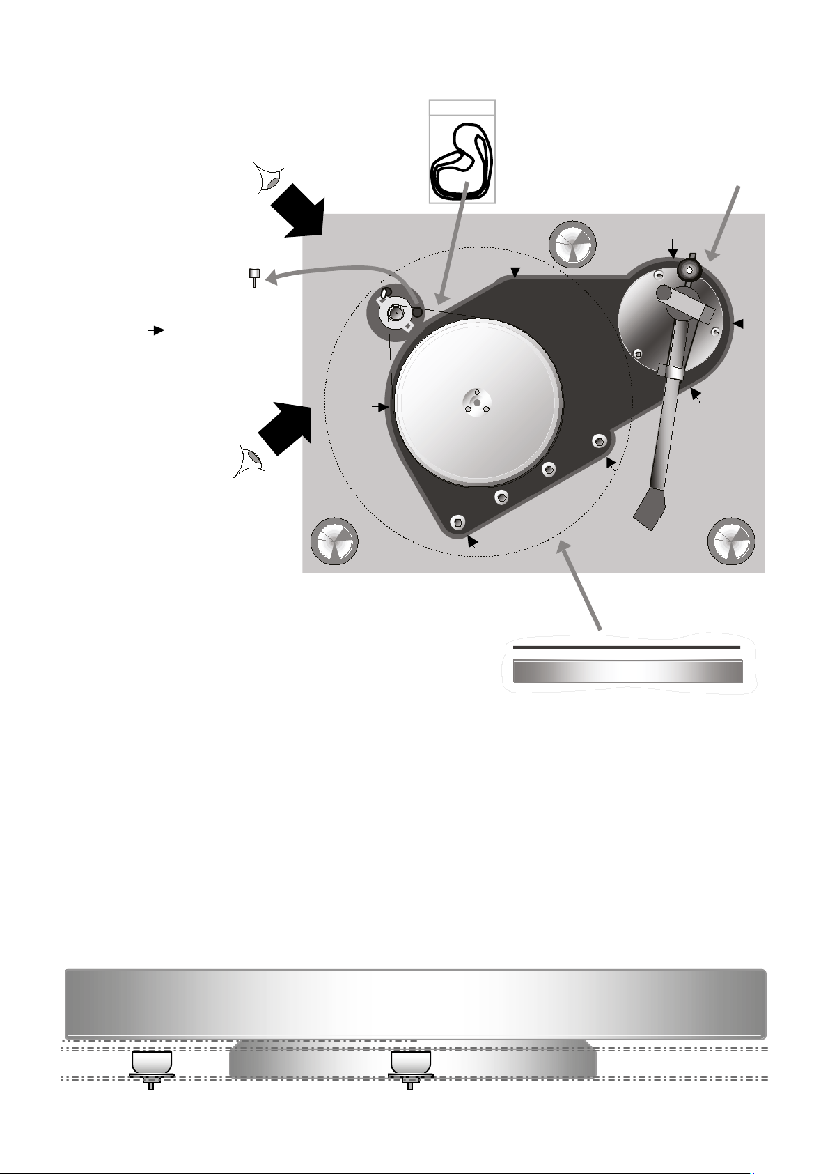
SETUP DIAGRAMS
NOTE: Tonearm/Counter weight and platters
must be tted when checking level adjustments
A.
2.
Sub-plinth should be
level with Top Plinth
all the way round
B.
Drive Belt Direction
To establish the correct Drive Belt
direction, try the Drive Belt inside
out rst and then upside down and
each time listen to nd out which way
round the music ‘ows’ better.
3.
4.
1.
Fitting the Drive Belt, Outer Platter and Level Adjustments
1 Carefully place/t Tonearm counter weight
2 Carefully remove the Motor Transit Screw (place in a bag and store in the packaging carton for future use)
3 Remove the Drive Belt from the bag and gently place it around the Inner Platter and the Motor Pulley (Note: The
Xerxes 20 Plus Turntable will perform better when the Drive Belt is not inside out and when it is the right way up!
To check for this consult Roksan Audio or your Roksan retailer/distributor)
4 Remove Outer Platter from the bag and gently place it upside down over the Inner Platter and seat it correctly on
its recess. To avoid marking/tarnishing the platters use the Cotton Gloves provided. (Be extra careful to ensure the
platter does not slip through your hands as this could seriously damage your Turntable)
5 Check the alignment of the Sub-plinth against the Top plinth by looking at the level all the way round (If necessary
realign the Sub-plinth; see below)
6 Check the alignment of the Motor Pulley against the Inner/Outer Platters by looking in the directions ‘A’ and ‘B’
(View the Top edge and the Flange of the Pulley to see if it is level with the Inner/Outer Platters) for this adjustment
see instructions below.
Motor Pulley and Inner/Outer Platter Alignment
View from A.View from B.
11
Page 14
Y
X
1
4
T
SETUP DIAGRAMS
NOTE:
Tilt Adjustment
Screw is under
The Inner Platter
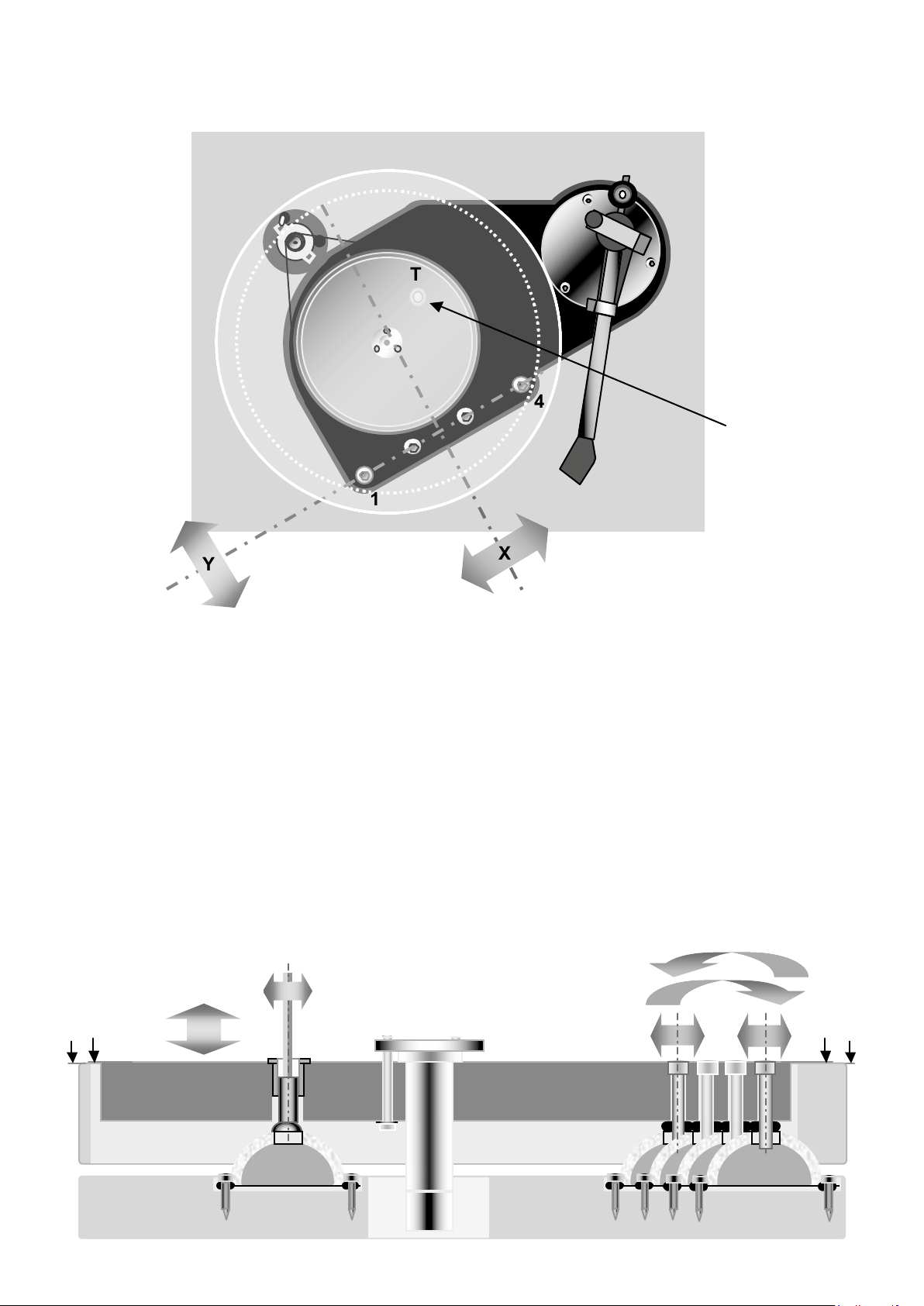
Plinth Assembly Tilt Adjustment
1 Gently tighten or slacken xing bolts 1 and 4 accordingly (using the 5mm A/F Allen key) to adjust
the level of the Sub-plinth/Inner Platter about the axis ‘X’ (Check that the Inner/Outer Platter
assembly is level with the Pulley; See view from ‘A’ above)
2 Gently tighten or slacken Tilt adjustment screw T (using the 3mm A/F Allen key) to adjust the tilt of
the Sub-plinth/Inner Platter about the axis ‘Y’ (Check that the Inner/Outer Platter assembly is level
with the Pulley; See view from ‘B’ above)
NOTE: Use a small, light, spirit level to check relative levels if necessary.
Tilt Adjustment About Axis ‘Y’
The Sub-plinth should be
level with the Top plinth.
Check the ‘level’ all the
way round. If necessary
realign the Sub-plinth.
Tilt Adjustment About Axis ‘X’
12 All specications are liable to change without notice. E&OE
Page 15
Left Hand Side
A
A
Sub-Plinth
Top Plinth
Bottom Plinth
Right Hand Side
SETUP DIAGRAMS
Platter
Correct Azimuth
! !
Platter
Incorrect Azimuth
Platter
Incorrect Azimuth
!
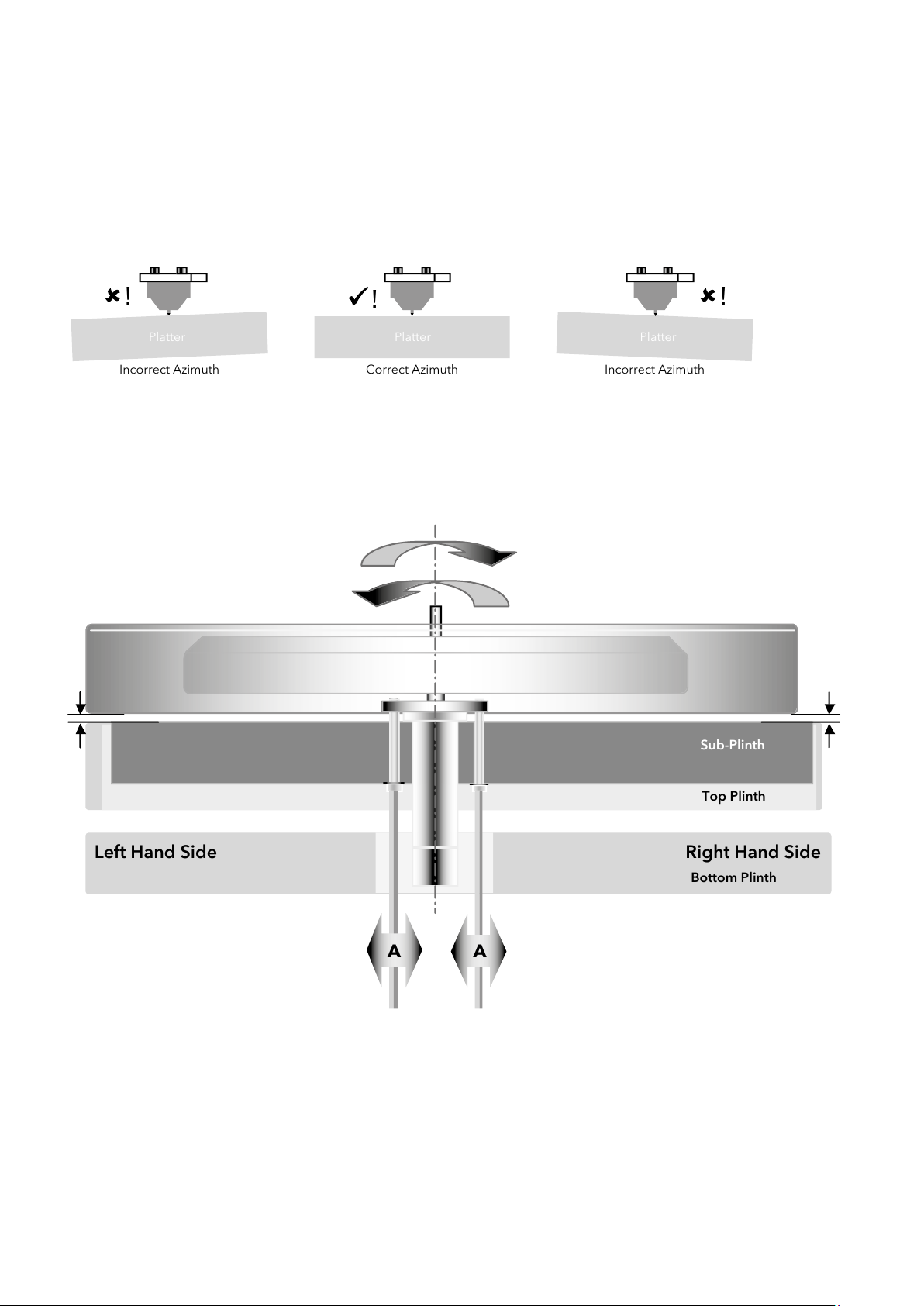
The Inner Platter is factory aligned and should be level with the Sub-plinth. Carefully place the Outer Platter the
right way up on the Inner Platter and observe the gap between the under side of the Outer Platter and the top
surface of the Sub-plinth. First look from the front of the Turntable and then from the side; the alignment of the
platter is achieved by adjusting the Main Bearing xing screws. There are 3 xing screws and tightening/slackening
these will tilt the axis of the Main Bearing and hence the platter level.
Platter level adjustment ensures correct azimuth between the platter/record and Tonearm Headshell.
If any adjustment is required, you must rst adjust the LEFT to RIGHT and then the FRONT to BACK. See below:
NOTE: The Fixing Bolt heads are not visible from the side gap
2.5mm A/F ALLEN KEY
Use a 2.5mm A/F Allen Key to adjust the Main Bearing Fixing Screws. Looking from the front adjusting the front two
screws will tilt the platter assembly LEFT to RIGHT as shown above. DO NOT over tighten or slacken the xing screws
too much. Correct tension is to have the screws tightened by 1–1.5 turn after they have come into contact with the
Sub-plinth. So when adjusting, slacken one a little and tighten the other a little. Adjustment of these two screws will
change the FRONT to BACK level. So you need to check the front to back level after adjusting the left to right level.
13
Page 16
B
Front Back
SETUP DIAGRAMS
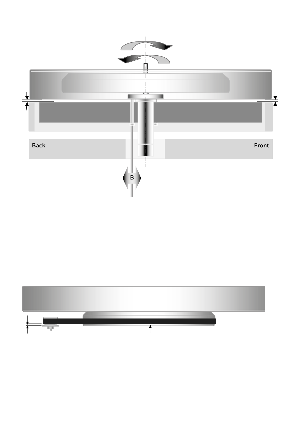
2.5mm A/F ALLEN KEY
Use the 2.5mm A/F Allen Key and looking from the left hand side, adjust the back (3rd) screw to tilt the platter
assembly FRONT to BACK as shown above. DO NOT over tighten or slacken the xing screw too much.
Adjustment of this screw will NOT change the LEFT to RIGHT level.
Drive Belt Riding Position
1 mm gap between the Drive Belt and the Pulley ange
Ref.: Pulley ange thickness is 1mm
The Drive Belt should ride with at least 2mm
clearance from the bottom of the Inner Platter
NOTE:
• With the Drive Belt riding higher on the pulley
(i.e. more than 1mm gap), the rotational speed
would be slightly increased
• With the Drive Belt riding lower on the pulley
(i.e. less than 1mm gap), the rotational speed
would be slightly decreased
14 All specications are liable to change without notice. E&OE
Drive Belt Setup and Maintenance
1 If the levels are adjusted but the Drive Belt rides a little
too high, then remove the Drive Belt and gently stretch
it. Wait a couple of minutes and ret the Drive Belt and
the Outer Platter and check the running position again
(Repeat this process if necessary).
Page 17
SETUP DIAGRAMS
A
A
Belt would ride slightly
higher on the pulley
Belt would ride slightly
lower on the pulley
View from B
Belt would ride slightly
higher on the pulley
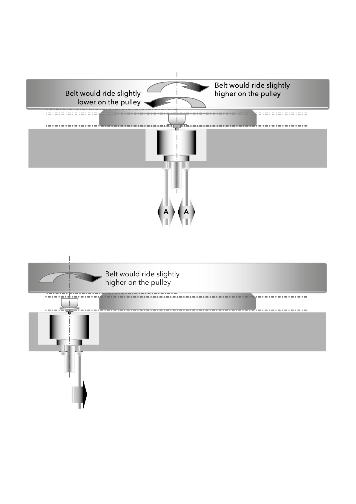
Motor Pulley and Inner/Outer Platter Alignment
View from A.
View from B.
2.5mm A/F ALLEN KEY
Drive Belt Setup and Maintenance
2 The Motor/Pulley axis can also be aligned just as the Main Bearing/Inner Platter axis. See above.
3 If the levels are adjusted but the Drive Belt rides a little too high, then remove the Drive Belt and
gently stretch it. Wait a couple of minutes and ret the Drive Belt and the Outer Platter and check
the running position again (Repeat this process if necessary).
15
Page 18
SETUP DIAGRAMS
Transit Pillar
Fixing Screw
Transit Pillar
Fixing Screw
Motor Spring
Motor
Bearing
Small Gap
Motor Axis
‘A’
Motor Free To
Rotate About
‘A’
Operation
Position
Transit
Position
Unscrew
and
Remove
16 All specications are liable to change without notice. E&OE
Motor Transit and Operation Modes
Always t the Transit Screw if the unit is to be transported/
shipped. There is no need to t this screw if you are merely
moving the Turntable or taking it in your car etc.
Page 19
Do Not
Pull Or Push
Bottom
Plinth
Armboard
Top
Plinth
Sub-Plinth
Tonearm Board
Fixing Screw
Tonearm Cable Gripped
Between Foam Strips
Tonearm Cable
Earth Wire
Tonearm Cable
Loose and Free
Platter/Bearing
Grounding Screw
SETUP DIAGRAMS
Tonearm Cable Dressing
Always ensure the Tonearm Cable is ‘free’ and ‘loose’ from the Tonearm to the plinth
as shown. It is important that the Sub-plinth and the Top plinth are ‘free’ and not
being pulled or pushed by the Tonearm Cable.
Note: The Xerxes 20 Plus Turntable has two foam strips tted in the Tonearm Cable
channel which can grip the Tonearm Cable and provide the necessary decoupling.
See above.
Please ensure the ground wire of the Tonearm Cable (where applicable) is attached
securely to the platter grounding screw.
17
Page 20
MAINTENANCE
Bearing Ball
Impression
No Bearing Ball
Impression
The Xerxes 20 Plus Turntable requires minimal user maintenance.
• The Main Bearing should be cleaned and recharged with Roksan Oil every 12-18 months.
Important to ensure the Main Bearing Ball is in the housing before recharging with oil.
• The Motor Pulley and Inner Platter should be cleaned every 6-12 months depending on frequency of use.
Both parts will periodically build up with small deposits of rubber where the Drive Belt runs around them.
Remove the Centre Piece, Rmat-7, Outer Platter and Drive Belt. Clean the Motor Pulley and Inner Platter using alcohol or
methylated spirit while they are still on the Turntable. DO NOT EXERT EXCESSIVE PRESSURE as damage may occur.
• Clean the Drive Belt with a non-alcohol wax based polish.
It is advisable to change the Drive Belt after every ve years or after ve thousand hours of use.
• Clean the dust cover with a damp cloth as and when required.
• The Turntable is made of very high quality real wood veneer (or high gloss lacquer) and should be looked after with
care. It may be cleaned with a very soft cloth. For any stubborn marks, use a very slightly moistened lint free cloth.
Very little high quality furniture wood polish may be used every 6-8 months.
DO NOT USE CLEANING AGENTS, SOLVENT OR ABRASIVES.
Refer to SETUP section above for detail on charging the Main Bearing with Roksan Supplied oil.
18 All specications are liable to change without notice. E&OE
Page 21
INSTALLATION
Foot at an angle and ‘tilted’
Foot straight and upright
Lower
Unit
Raise
Unit
ADJ.
FOOT
Your Xerxes 20 Plus Turntable is designed to work on a level, light, vertically rigid non-resonant surface. If the unit is to be
on a oor mounted Hi-Fi rack, then ensure the rack is vertically rigid. It is not as important if the rack is slightly compliant
side ways. Please ensure the surface on which the Turntable is to be placed is reasonably level. Remember the type of
‘shelf’ material can signicantly affect the performance of any Hi-Fi equipment especially Turntables.
Please ensure this surface is as rigid and as non-resonant as possible.
Note: It is not necessary to have this surface over damped with sound absorbent material.
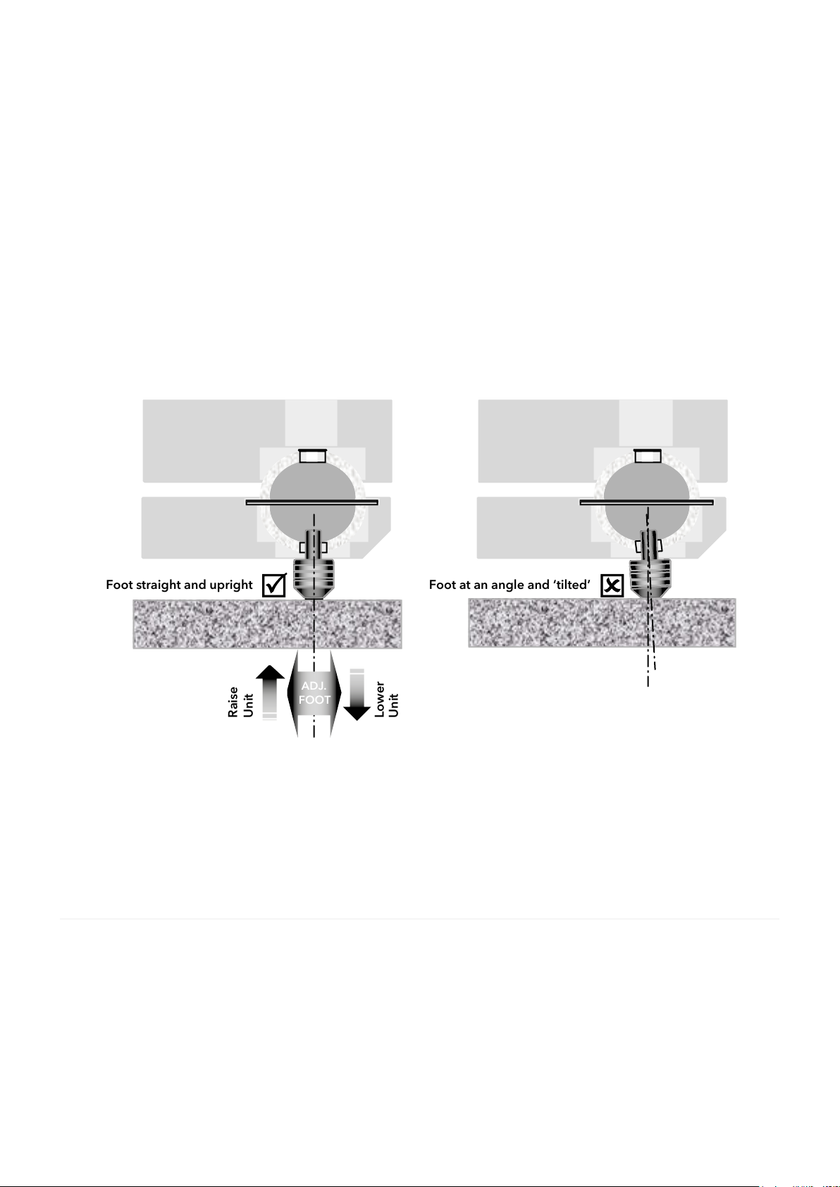
Note: The Xerxes 20 Plus Turntable feet are adjustable and they are attached to the lower decoupling domes and thus are
part of the structural ‘suspension’ of the unit. These can be used to ne tune the level of the Turntable, but they must not
be at an angle/tilted to the side. Your Xerxes 20 Plus Turntable works much better when its feet are straight and upright.
It is equally important to ensure the Tonearm Cable and the Motor Drive Lead are not pulling or pushing the Turntable
plinth. Otherwise they will act as feed-back ‘channels’ and also ‘tilt’ the Turntable slightly and thus move the feet out of
their upright position. Take care when dressing these cables to avoid mechanical strain and remember not to run these
alongside mains power or speaker cables.
If the unit is to be used on a wall mounted shelf, please ensure the same.
In either case, follow the rack/shelf manufacturer’s instructions but do ensure good mechanical integrity
of the structure on which your Xerxes 20 Plus Turntable is to be sited.
Consult your Roksan distributor, retailer or Roksan Audio if you have any queries.
OPERATION
Switch on the dedicated Xerxes Power Supply and choose the desired speed. The platter should start turning.
Place the record on the Rmat-7 ensuring the centre piece is in place. When the record is on the platter remove the
Centre Piece and place it in Spindle Cap rest on the Top plinth. When you are not using the Turntable either leave
the Xerxes Power Supply on but in standby or switch it off completely.
19
Page 22

TROUBLESHOOTING
If you suspect that your Roksan Xerxes 20 Plus Turntable is not operating properly, rst check all the connections carefully.
Below are some likely encountered problems with suggestions for possible cure.
The list is not exhaustive: If you have any unresolved problems, please consult your appointed Roksan dealer or distributor.
SYMPTOM LIKELY CAUSE SUGGESTED REMEDY
Platter not turning Motor Drive Lead not inserted properly
Motor Drive not switched on
Drive Belt not tted
Start-up too slow (>10sec.) Motor locked in transit position
Belt dirty or sticky
Main Bearing ‘dry’
Main Bearing ball missing
Belt falling off
Platter touching the plinth
Incorrect Motor alignment
Incorrect Main Bearing alignment
Ensure Motor Drive Lead is fully inserted
Switch Motor Drive on
Fit Drive Belt and try again
Remove Motor Transit
Clean Drive Belt with wax based furniture polish
Check, if no damage to Bearing, recharge with
Roksan Main Bearing Oil (see above)
Check, if no damage to Bearing, t new Xerxes
20 Plus Main Bearing ball (if in doubt consult
your Roksan retailer)
Check and realign Motor (see above)
Check and realign Bearing (see above)
WARRANTY
There are no user-serviceable parts on your Xerxes 20 Plus Turntable. If a fault should develop,
refer any servicing to your appointed Roksan dealer, distributor or approved service agent.
Your Roksan Xerxes 20 Plus Turntable warranty covers against any defect in materials and
workmanship for a period of ve years from the date of purchase.
This warranty excludes:
1 Damage caused due to accident, misuse, neglect and incorrect installation, adjustment or repair.
2 Liability for damage or loss during transit from the retailer or purchaser to Roksan or its authorised
distributor for the purposes of repair or inspection.
Carriage costs to Roksan shall be borne by the consignor.
All claims under this warranty must be made through an authorised Roksan retailer.
If equipment returned for repair to Roksan is found on inspection to comply with the product
specication Roksan reserves the right to make a charge for examination and return carriage.
Unauthorised servicing will void this warranty.
20 All specications are liable to change without notice. E&OE
Page 23

SPECIFICATIONS
Main Bearing Spindle Hardened tool steel
Roundness & Concentricity < 5 Microns
Length to Diameter ratio 11:1
Main Bearing Ball Super precision Tungsten Carbide
Roundness < 1 Micron
Diameter 2mm
Main Bearing Housing Solid Phosphor Bronze
Clearance 2/1,0000”
Inner Platter 2 Piece Solid Aluminium alloy
Interference tted non-resonant
Outer Platter 2 Piece Solid Aluminium alloy
Interference tted non-resonant
Structure 3 Plinth Design
Isolation 3 Level De-coupling
Motor Custom made 24 pole synchronous
Pulley Solid Aluminium alloy
Roundness & Concentricity < 1 Micron
Drive Belt Precision ground Neoprene
Motor Mount Unique synchronizing bearing
Motor Drive External speed controller
Wow and Flutter < 0.02%
Rumble < -80dB
Dimensions 450 x 370 x 115mm
Weight 12 kg
NOTES
Xerxes 20 Plus Turntable Number Serial ………………………………
Purchase Date Year .……… Month .……… Day .………
Roksan Retailer Name: …………………………………………
Location: ………………………………………
………………………………………………….
………………………………………………….
Please keep a record for future reference
Printed in England
21
Page 24

Roksan
24 Brook Road, Rayleigh
Essex, SS6 7XJ, UK
+44 (0)1268 740 580
roksan.com
06/18
 Loading...