

Page 1
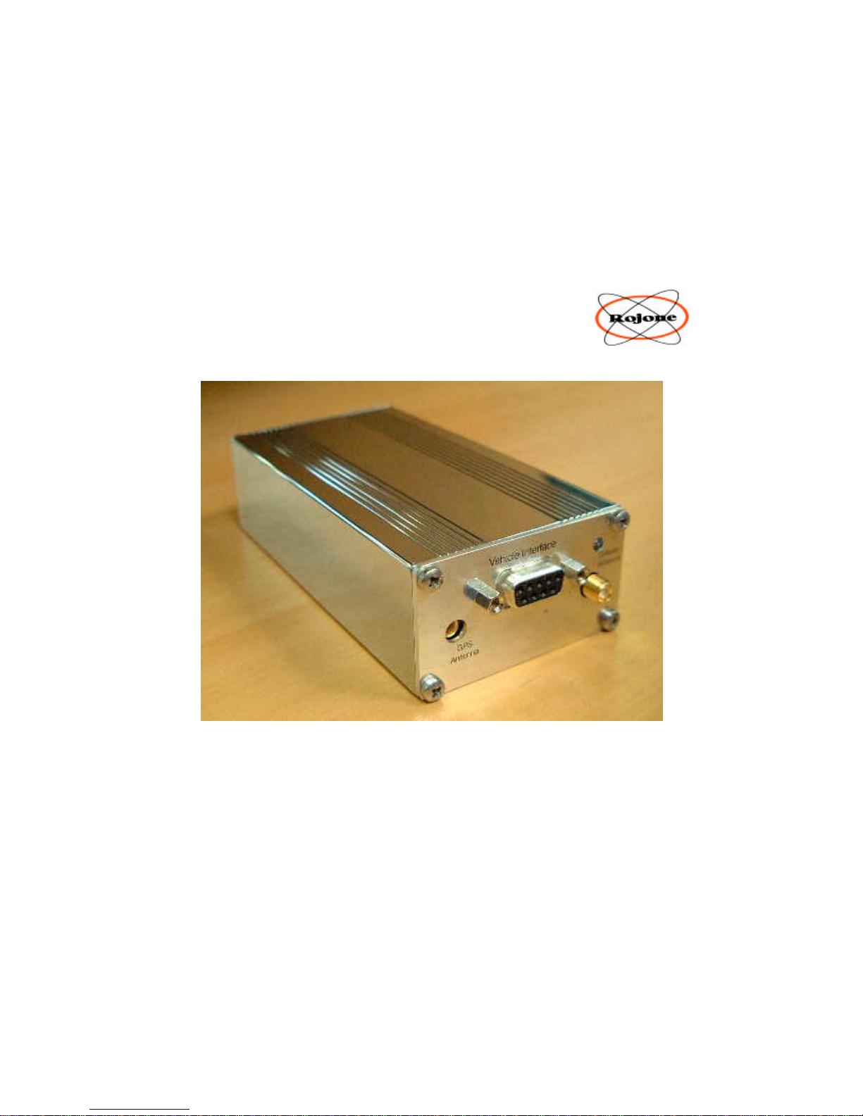
Rojone
EziTraKTM
Personal Vehicle Tracking System
Installation Manual
Installation and Setup for
Global Positioning System Personal Vehicle Monitor
Model # EZIPVM-2003
Patent Australia # 40291 Manual Issue : August 2003-08-25
United State # 09/847492
Page 2

ROJONE Pty. Ltd – 61 Aero Rd, INGLEBURN NSW 2565 AUSTRALIA
TEL +61 02 9829 1555 FAX 02 9605 8812 EMAIL [email protected]
1
Page 3

ROJONE Pty. Ltd – 61 Aero Rd, INGLEBURN NSW 2565 AUSTRALIA
TEL +61 02 9829 1555 FAX 02 9605 8812 EMAIL [email protected]
2
EziTrak ™
Vehicle Monitor, Black Box
Emergency Alarm &
Tracking System
Technical Manual (Australian / European Vehicle Monitor)
GSM Cellular Version, English Vocabulary
Software Version 3.6 - October 1st, 2003
Manual Release R1.6
CONTENTS
1.0 GENERAL INFORMATION
6.0 SPECIFICATIONS
6.1 DC CHARACTERISITICS
6.2 MECHANICAL
6.3 VEHICLE INTERFACE
6.3.1 VEHICLE INTERFACE Connector
6.3.2 EziTraK™ Front Panel Drawing
6.3.3 INSTALLATION
6.3.4 EziTraK™ Vehicle Interface Drawing
6.3.5 EziTraK™ Relay Schematic
6.3.6 EziTraK™ Fuel KILL Relay Connection
6.3.7 EziTraK™ Ignition KILL Relay Connection
6.3.8 EziTraK™ Lock and Unlock Relay Connection
6.3.9 EziTraK™ Input Sensor Schematic
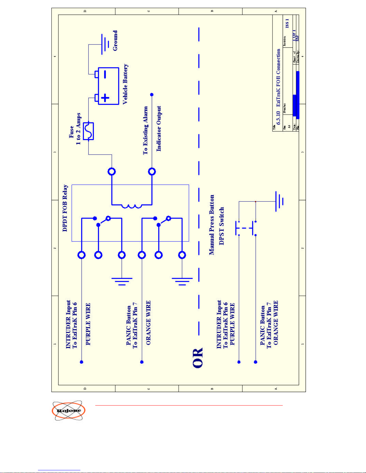
6.3.10 EziTraK™ FOB Connection
6.4 Cellular Telephone ANTENNA
6.5 GPS ANTENNA
6.6 SIM Card
7.0 APPENDIX A - SETUP Procedure
8.0 APPENDIX B - Water Proofing Installation
9.0 APPENDIX C - RESET Procedure
10.0 APPENDIX D - Contents of EziTraK™ Kit
11.0 APPENDIX E - Disclaimer
12.0 APPENDIX F - WARRANTY
Page 4

ROJONE Pty. Ltd – 61 Aero Rd, INGLEBURN NSW 2565 AUSTRALIA
TEL +61 02 9829 1555 FAX 02 9605 8812 EMAIL [email protected]
3
1.0 GENERAL INFORMATION
The EziTraK™ is a low cost high performance Vehicle Security System which provides you with instant direct
communications with your vehicle at all times allowing you to track it and take control of it using any wireline touch
tone phone, mobile phone or Personal Computer from anywhere in the world.
The EziTraK™ allows you to locate and control your vehicle using either
1. A standard Voice call
2. SMS messaging commands
3. ON-Line via a PC, Modem and EziTraK™ PC Application Software
The EziTraK™ continually monitors the following Functions
Emergency PANIC Button
Intruder Detection Input
Ignition Detection Input
Main Power Input
Tow Away Detection
Overspeed Detection
Black Box Recorder
The EziTraK™ talks to you in a friendly female voice in your own language.
The Voice menu allows you to
Find out your Vehicle’s GPS Co-ordinates, Position Speed and Heading
Listen to a Status Report
Control the Alarm System
Disable the Vehicle
Set your Home Base Position
Set your Intruder and Emergency Phone Numbers
Set your PIN Number
The EziTraK™ can automatically dialout up to 4 Phone Numbers.
2 Voice Call Numbers and 2 SMS Numbers
All EziTraK™ Functions and Phone Numbers can be easily Setup using a simple SMS Messages
Other Features Include
PIN Number protection
Automatic Alarm System Arming
External Sealed Lead A cid Backup Battery Input
Voice, SMS and ON-Line control
Silent Dial Out Alarm
Internal BLACK BOX Recorder
Caller ID Alarm Control
Miles, Kilometres or Nautical Miles selection
ON-Line Moving Map Display capable
Page 5

ROJONE Pty. Ltd – 61 Aero Rd, INGLEBURN NSW 2565 AUSTRALIA
TEL +61 02 9829 1555 FAX 02 9605 8812 EMAIL [email protected]
4
!
The EziTraK™ requires a GSM SIM Card, not supplied, with Voice and SMS Phone Number and optional Data Call
Number if the user requires access via a PC and Modem.
The EziTraK™ is a Personal Monitoring System so there are NO Third Party fees to pay unlike many Back To Base
Systems which require you to pay ongoing fees for many years costing typically many thousands of dollars. Your
EziTraK™ belongs to you.
Your EziTraK™ will operate in any country with compatible GSM Network and SIM Cards.
Full functionality is best achieved in areas with both GSM Network Service and GPS satellite broadcast signal. Wide
open outdoor areas are ideal for the GPS satellite receiver. GPS receivers can suffer interference from transmitting
devices which may cause dropouts in GPS coverage but this is generally uncommon and more likely in large
commercial centres. The EziTraK™ will continue operating without either service necessarily available. If the GPS is
unavailable the EziTraK™ will remember the last position with GPS service available and provide you with that
information.
The purpose of this manual is to provide you with the most important information to allow the best operation and
performance for your EziTraK™. Please take the time to thoroughly read all the information provided.
It is Important for you to also become familiar with all operational aspects of the monitoring system.
The specifications presented herein should be used for guidance only and are subject to change
without notice.
ROJONE Pty Ltd
ACN 002 691 241
61 Aero Road
Ingleburn, NSW 2565
Australia
Contact:
Tel: +61 2 9829 1555
Fax: +61 2 9605 8812
V isit our web site:
www.rojone.com.au
WARNING: TO REDUCE THE RISK OF FIRE OR
DAMAGE TO THE EQUIPMENT, DO NOT EXPOSE THIS
DEVICE TO RAIN OR MOISTURE.
Page 6

ROJONE Pty. Ltd – 61 Aero Rd, INGLEBURN NSW 2565 AUSTRALIA
TEL +61 02 9829 1555 FAX 02 9605 8812 EMAIL [email protected]
5
6.0 SPECIFICATIONS
All specifications are Preliminary and are subject to change.
6.1 DC CHARACTERISITICS
Input Voltage 12 to 24 VDC with Negative Earth.
DC Current Standby 10 mA @ 12V ( 8 mA @ 24V)
Tow Away Mode ON 35 mA @ 12V (25 mA @ 24V)
Maximum 200 mA @ 12V (150 mA @ 24V)
Reverse Polarity Protection Series Diode
Over Voltage Transient Shunt
Battery Backup Input Same as Input Voltage Volts DC
Operating Temperature -20 to +60 Degrees Celcius
A vehicle’s power supply system should be regularly checked and maintained for reliable performance. Less
frequently used systems should be backed up using a solar charger.
6.2 MECHANICAL
DIMENSIONS
LENGTH 115 mm
WIDTH 61 mm
HEIGHT 35 mm
WEIGHT 800 grams
MATERIAL Electro-less Nickel Plated Aluminium extrusion
MOUNTING
The unit can be quickly and easily mounted using cable ties. Be sure to locate the unit in a dry place out of
direct sunlight and high temperatures with good ventilation. The cable end should be orientated away from any
possible water source.
WATER PROOFING
The water proofing supplied with the EziTraK™ kit consists of 2 plastic boots,
some silicon grease, cable ties and a water absorbing Desiccant Bag. The unit is must NOT be immersed in
water but will survive a moist environment if properly installed and maintained.
Page 7

ROJONE Pty. Ltd – 61 Aero Rd, INGLEBURN NSW 2565 AUSTRALIA
TEL +61 02 9829 1555 FAX 02 9605 8812 EMAIL [email protected]
6
6.3 VEHICLE INTERFACE
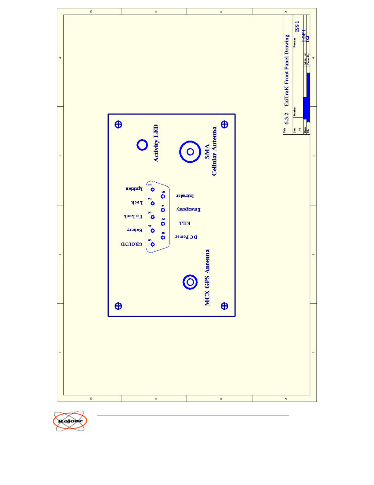
6.3.1 VEHICLE INTERFACE Connector
The VEHICLE INTERFACE is a 9 Pin Female D-Sub miniature Connector.
Pin-out and Wire Loom Colors listed below …
PIN Number FUNCTION Description
9 RED + 12 VDC Constant Battery Power
Main Vehicle Battery
+12 to +24 Volts
5 BLACK Ground Main Vehicle Battery Ground
4 WHITE Battery Backup Connect to Backup Battery Positive +12 VDC
Take Backup Battery Ground to Chassis or
Main Vehicle Battery Ground.
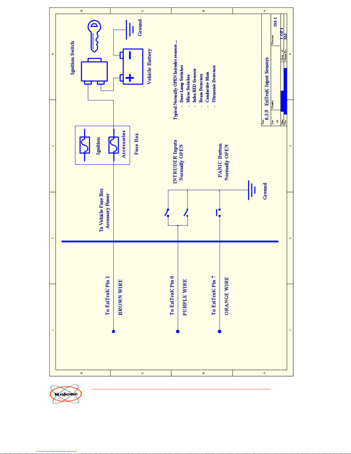
1 BROWN IGNITION +12 VDC Power Input from Accessory Fuse .
6 PURPLE INTRUDER Connect Through Door Switch to Ground.
Switch Contact should be Normally Open
7 ORANGE EMERGENCY Connect Through Panic Switch to Ground.
Switch Contact should be Normally Open
8 YELLOW Vehicle KILL Open Collector Output or Ext Relay Drive
NOTE : 100 mA maximum current Sink.
Suitable for connection to vehicle Computer.
Suitable for connection to supplied relays.
2 GREEN LOCK Open Collector Output or Ext Relay Drive
NOTE : 100 mA maximum current Sink.
3 BLUE UNLOCK Open Collector Output or Ext Relay Drive
NOTE : 100 mA maximum current Sink.
We advise using the external isolating relays provided in the Kit on all outputs.
These relays isolate the vehicle’s electronic systems from the Unit allowing the control of almost any configuration of
vehicle electrical system. DO NOT CONNECT THE OUTPUTS DIRECTLY TO HIGH CURRENT
SOLENOIDS.
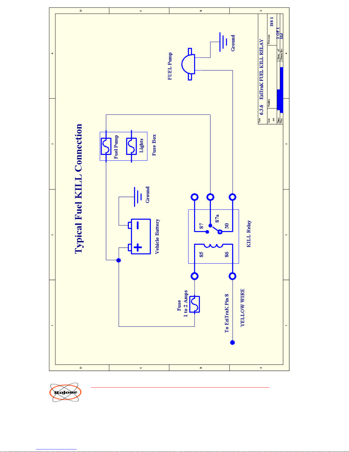
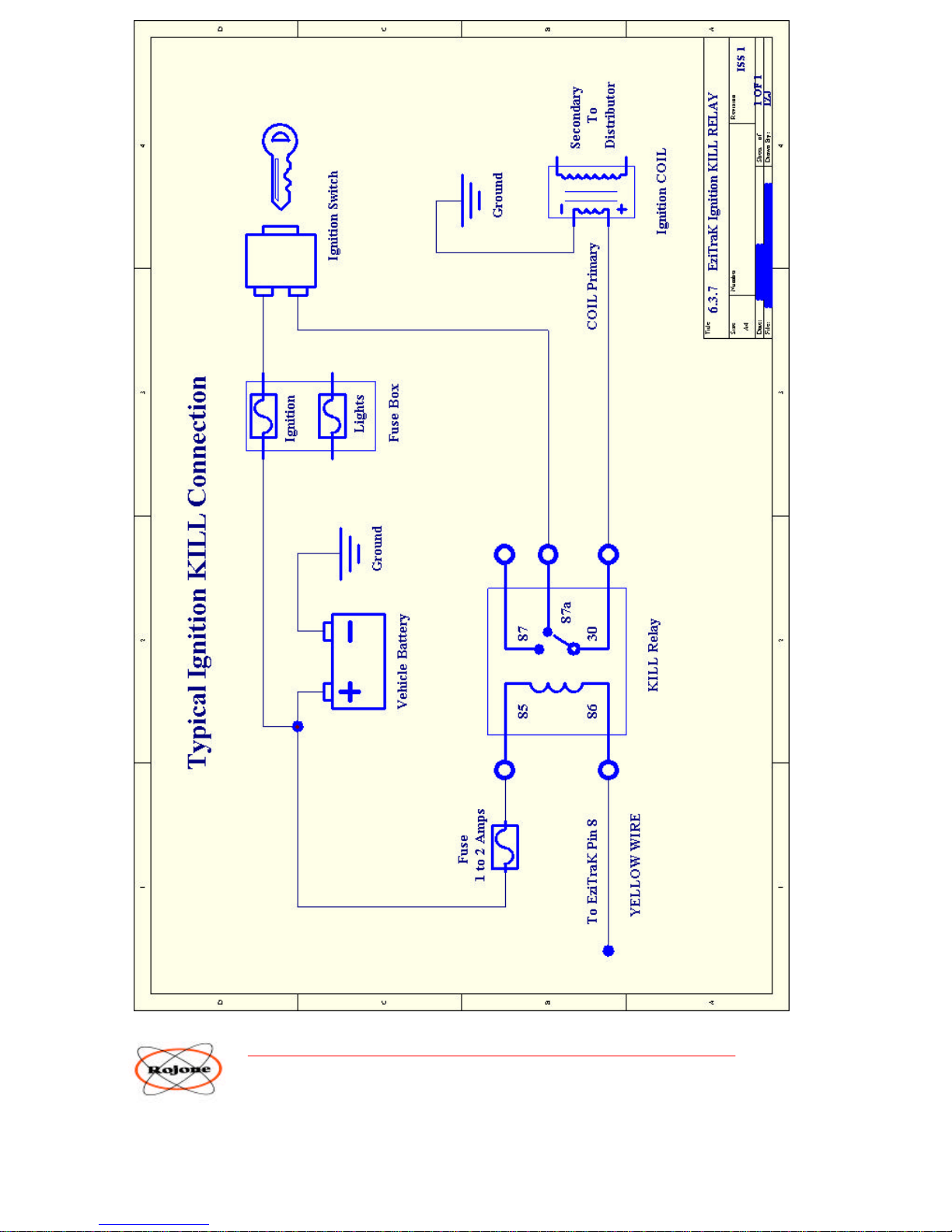
NOTE : Two different connection methods are shown for vehicle engine Kill, for either fuel starvation or ignition
system electrical shutdown. Generally electrical Kill is more direct and immediate. Your installer should be able
to recommend which is the most suitable type of Engine Kill and connection method for your vehicle.
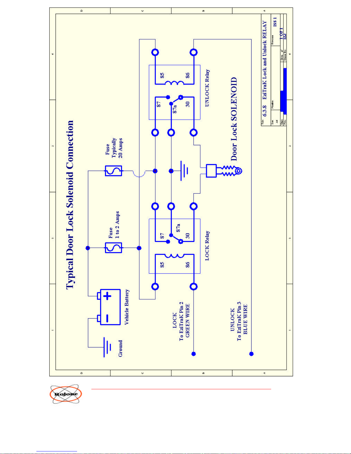
Your Installer should also be consulted as to the best method of connecting to the Central Locking System of
your particular vehicle. One example of Vehicle Lock and Unlock method is also shown.
Page 8
ROJONE Pty. Ltd – 61 Aero Rd, INGLEBURN NSW 2565 AUSTRALIA
TEL +61 02 9829 1555 FAX 02 9605 8812 EMAIL [email protected]
7
Page 9

ROJONE Pty. Ltd – 61 Aero Rd, INGLEBURN NSW 2565 AUSTRALIA
TEL +61 02 9829 1555 FAX 02 9605 8812 EMAIL [email protected]
8
6.3.3 INSTALLATION
The EziTraK™ Vehicle Interface requires a wiring loom to the Vehicle through the 9 Pin DSub Connector.
Please refer to 6.3.2 EziTraK™ Front Panel Drawing.
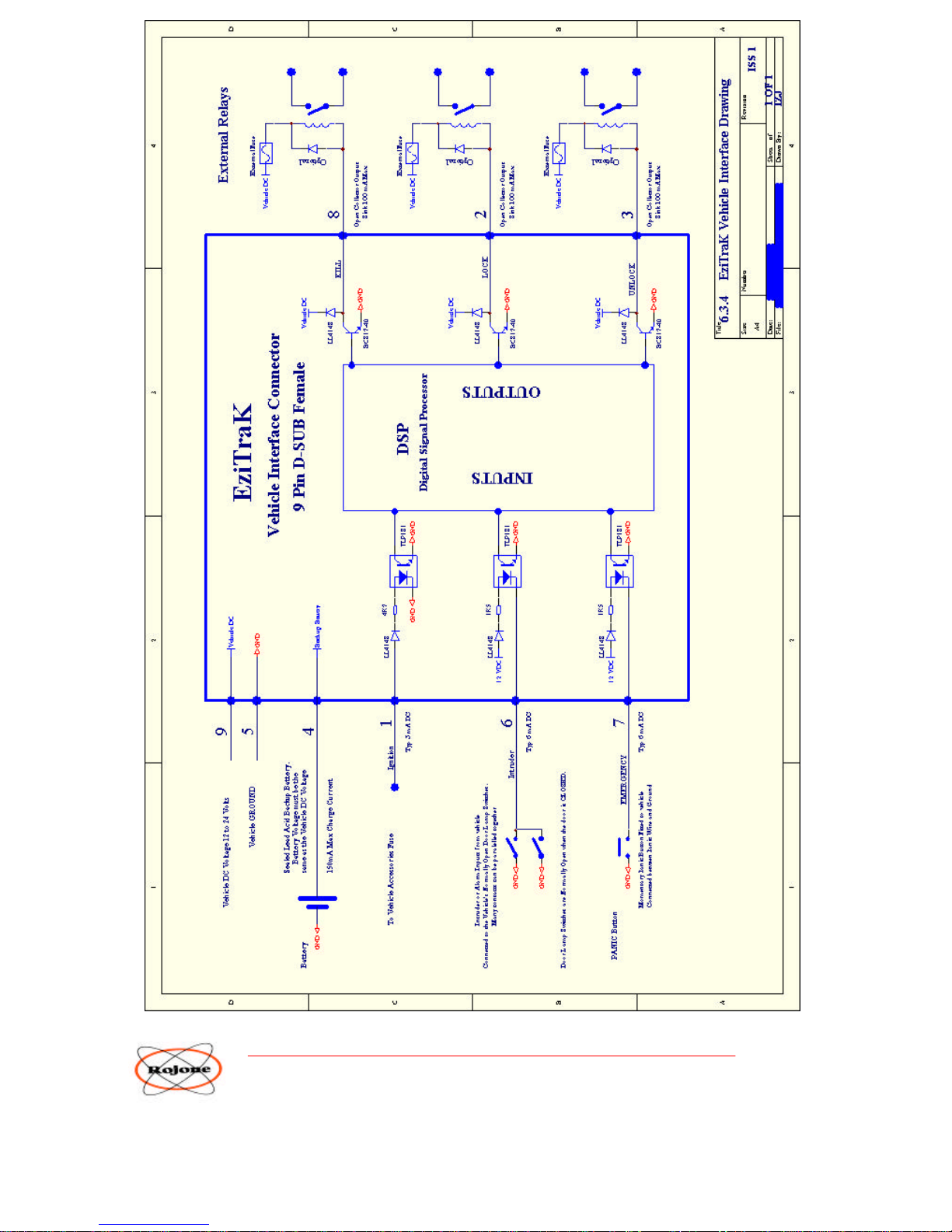
Pin 9 Connects to the Vehicle's battery. This is a Permanent Power connection and
should be connected to the battery using a 5 Amp Fuse in series.
Pin 5 Connects to the Vehicle ground.
Pin 4 Connect a 12 volt Sealed Lead Acid battery typical of alarm backups to this pin.
Pin 4 is the positive of the battery and connect the negative to the Vehicle ground.
Pin 1 IGNITION Input. This pin should be connected to accessories power at the fuse box.
Input 0 Volts is ignition OFF, Input 12 to 24 Volts is ignition ON.
Pin 6 INTRUDER Input. Connect this pin to the normally open Door Switch of the vehicle. Normally open
when the door is closed. This input should be Normally Open and detection occurs when the switch
is connected to ground, i.e. doors are opened.
Pin 7 EMERGENCY Input. Connect the PANIC Button between this pin and Ground. The Button should
be Normally Open and detection occurs when the switch is connected to ground.
OUTPUTS
Outputs on pins 8, 2 and 3 are electrically the same. All pins are connected to the Collector of a Transistor
providing an electronic switch to ground. The maximum continuous current is 100 mA Sink. (i.e. into the pin
to ground.) The outputs are also protected by an internal Flyback diode.
These outputs are called OPEN COLLECTOR OUTPUTS. Open collector outputs can be connected directly to
Vehicle systems such as solenoids and relays so long as the maximum current is not exceeded.
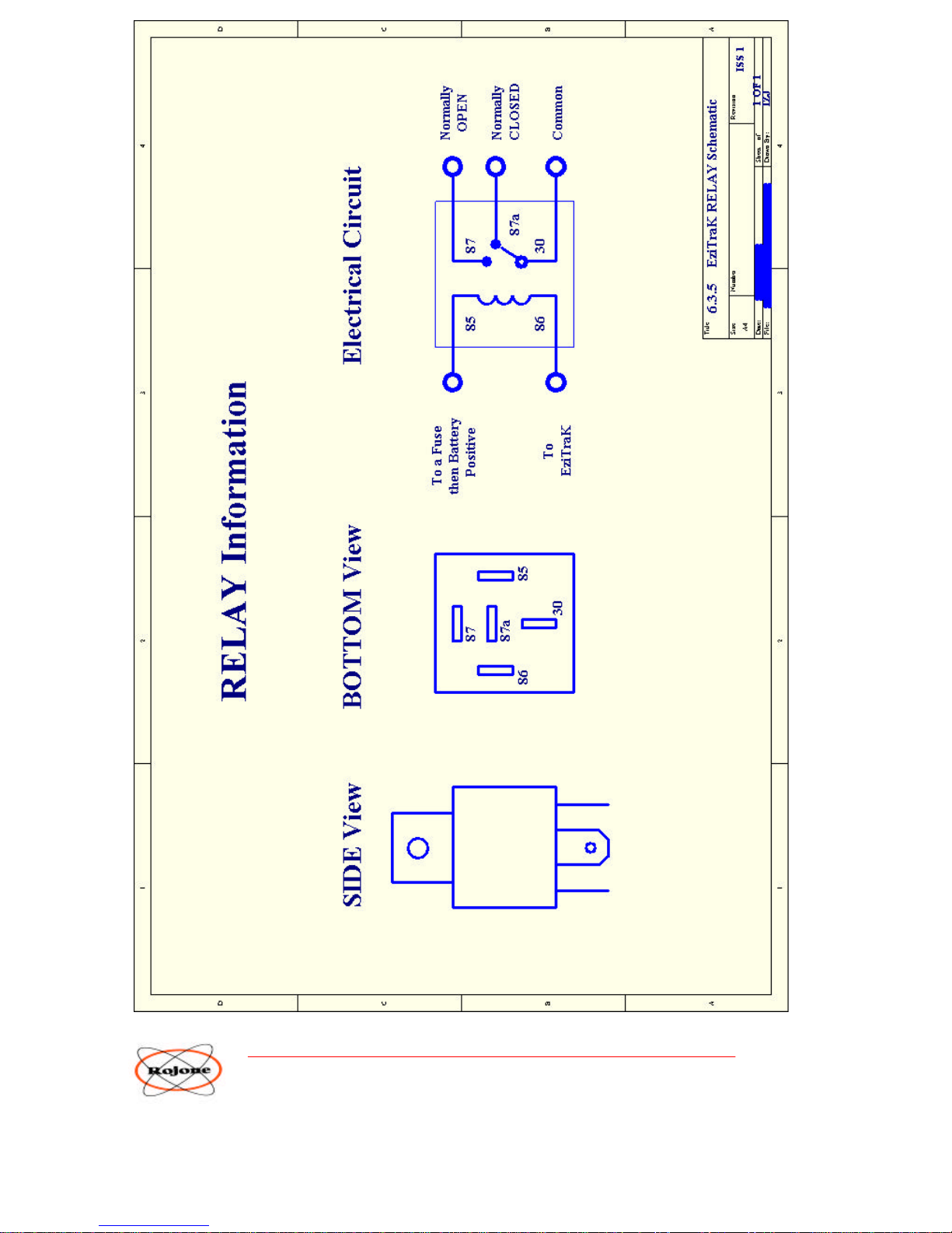
It is recommended that an external isolation relay, provided with the EziTraK™ kit, be used to control the
Vehicle electrical system. These are a typical automotive relays, with 100 mA max coil current and 20 Amp
secondary contact rating.
The relays secondary contacts can then be connected to the Vehicle's electrical system wi th full isolation from
the EziTraK™. NOTE : Do NOT exceed the control relay’s secondary contact rating.
Pin 8 KILL Output. This usually connects through an isolating relay to the Vehicles's fuel pump or ignition
system. Always test the effectiveness of your connection method after installation. A manual Kill
Override switch can be connected in series with this output wire before the Kill Relay in case of
emergencies.
Pin 2 LOCK Output. This Lock Output should be connected to the Lock relay supplied, to
control the Door lock solenoids. Please ensure not to exceed the electrical ratings of the control
relay supplied with the EziTraK™ Kit.
Pin 3 UNLOCK Output. This Unlock Output should be connected to the Unlock
relay supplied, to control the Door Unlock solenoids. Please ensure not to exceed the electrical ratings of the
control relay supplied with the EziTraK™ Kit.
Page 10

ROJONE Pty. Ltd – 61 Aero Rd, INGLEBURN NSW 2565 AUSTRALIA
TEL +61 02 9829 1555 FAX 02 9605 8812 EMAIL [email protected]
9
IMPORTANT INSTALLATION INFORMATION
INTRUDER Input
The Intruder Input wire is normally connected to the door switch in a vehicle in which the switch contacts are OPEN
when the doors are closed and CLOSED when either one door or both doors are open. When the doors are opened the
switch connects to ground and turn on the interior light.
This same connection to ground is used to trigger the Intruder Input. This is a very standard connection method for most
alarm systems.
Some vehicles though, particularly modern vehicles, may have door switches which operate differently.
Some modern door switches are momentary. This means that the switch closes when the door is opened but they
quickly opens again even when the door stays open.
Page 11
ROJONE Pty. Ltd – 61 Aero Rd, INGLEBURN NSW 2565 AUSTRALIA
TEL +61 02 9829 1555 FAX 02 9605 8812 EMAIL [email protected]
10
Page 12
ROJONE Pty. Ltd – 61 Aero Rd, INGLEBURN NSW 2565 AUSTRALIA
TEL +61 02 9829 1555 FAX 02 9605 8812 EMAIL [email protected]
11
Page 13
ROJONE Pty. Ltd – 61 Aero Rd, INGLEBURN NSW 2565 AUSTRALIA
TEL +61 02 9829 1555 FAX 02 9605 8812 EMAIL [email protected]
12
Page 14
ROJONE Pty. Ltd – 61 Aero Rd, INGLEBURN NSW 2565 AUSTRALIA
TEL +61 02 9829 1555 FAX 02 9605 8812 EMAIL [email protected]
13
Page 15
ROJONE Pty. Ltd – 61 Aero Rd, INGLEBURN NSW 2565 AUSTRALIA
TEL +61 02 9829 1555 FAX 02 9605 8812 EMAIL [email protected]
14
Page 16
ROJONE Pty. Ltd – 61 Aero Rd, INGLEBURN NSW 2565 AUSTRALIA
TEL +61 02 9829 1555 FAX 02 9605 8812 EMAIL [email protected]
15
Page 17
ROJONE Pty. Ltd – 61 Aero Rd, INGLEBURN NSW 2565 AUSTRALIA
TEL +61 02 9829 1555 FAX 02 9605 8812 EMAIL [email protected]
16
Page 18

ROJONE Pty. Ltd – 61 Aero Rd, INGLEBURN NSW 2565 AUSTRALIA
TEL +61 02 9829 1555 FAX 02 9605 8812 EMAIL [email protected]
17
6.4 Cellular Telephone ANTENNA
The GSM Telephone Antenna Connector is an SMA Female.
The GSM phone is a Dual Band 850 / 1900 MHz system.
The Cellular antenna provided with the EziTraK™ kit is designed to be mounted on an internal glass
window, plastic window or on the inside of a fibreglass panel.
This Cellular antenna must NOT be mounted to a metal surface as this will severely detune the antenna
and provide poor performance. An alter native antenna such as a half wave or quarter wave vertical may be
used but it must have an Impedance of 50 Ohms and operate at the frequency of your Service Provider,
either 850 MHz, 1900 MHz or both.
If an external antenna is used then it should be protected from the weather and maintained regularly. If a
coaxial extension cable is used then the cable loss should be minimised so as not to reduce GSM
performance. All antenna installations should be checked and tested regularly and connectors shoul d be
coated in silicon grease or some other sealant.
6.5 GPS ANTENNA
The GPS Antenna Connector is an MCX Female.
DC Output on centre contact is +3VDC. Shield is Ground. Maximum current source is 40 mA.
WARNING: Do NOT short the centre contact to ground or you may damage the Receiver.
The GPS Antenna should be mounted ideally
1. Out in the open
2. and On a Ground Plane
3. and Above other structures
It is not always easy to comply with all of these requirements.
If the GPS antenna needs to be mounted under a surface of some kind then this will possibly degrade the GPS
performance. To help combat this problem it is important to place the antenna on a ground plane when
mounted under a surface. The magnetic mount allows the antenna to attach easily to any ferrous metal ground
plane which should be properly sealed from the environment. Non ferrous ground planes are also suitable for
use. Gluing or attaching a magnet below some non ferrous metal ground planes will allow magnetic mounting.
Be sure to first put the two magnets together, antenna magnet and mounting magnet, and find out which poles
need to face each other.
Ground planes are best when square or circular with the antenna mounted in the centre. A minimum 2 to 4
inches (50 to 100 mm) diameter is recommended. Anything larger than this then the shape is generally of no
concern. Try not to use a corrugated surface on the ground plane as they cause multi-path reflection which
interferes with GPS. Flat grounds are best and cause less reflection. If you have to mount on a corrugated
surface then mount the antenna on a flat metal ground ABOVE the corrugated surface as high as possible. The
two grounds can be electrically connected using a mounting pole if required.
Never mount the antenna under a metal surface. Plastic, wood or fibreglass surfaces are OK but ensure they are
as thin as possible. The thicker the surface the weaker the GPS signal will be. Also try to mount the antenna
about 1 inch (25mm) below the surface. Do NOT mount the antenna hard up against any
surface.
Page 19
ROJONE Pty. Ltd – 61 Aero Rd, INGLEBURN NSW 2565 AUSTRALIA
TEL +61 02 9829 1555 FAX 02 9605 8812 EMAIL [email protected]
18
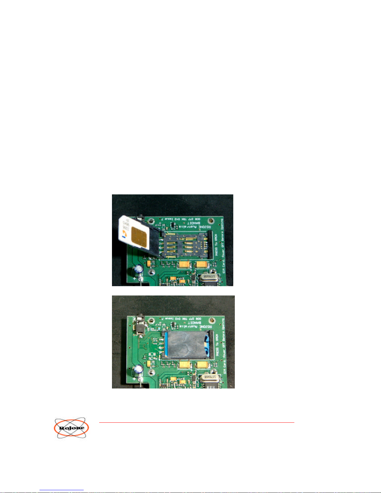
6.6 SIM Card
The SIM Card MUST be fitted Prior to applying DC power to the unit.
The SIM card MUST be Data Enabled if you require data access via a PC and Modem.
This is Important, as without a Data Enabled SIM card the unit will connect
to an incoming modem but it will be unable to pass data.
Your Network Provider should be able to Data Enable your SIM Card.
NOTE : Your EziTraK™ uses the GSM Cellular system and so requires a SIM Card. This SIM Card carries
the EziTraK™’s phone number. Some Network Service Providers require the SIM Card to have two phone
numbers, one for Voice Calls and one for Data Calls. Some Network Service Providers only require the one
phone number for both Voice and Data. Be sure you are aware which type of service you have available.
When connecting to your EziTraK™ Online be sure to use the correct phone number.
IMPORTANT : Your EziTraK™ SIM Card should have the …
SIM Card PIN Number DISABLED
Re-Direction, Call Waiting, Message Bank etc DISABLED
ALL Automatic services should be DISABLED
Page 20
ROJONE Pty. Ltd – 61 Aero Rd, INGLEBURN NSW 2565 AUSTRALIA
TEL +61 02 9829 1555 FAX 02 9605 8812 EMAIL [email protected]
19
7.0 APPENDIX A - SETUP Procedure
The EziTraK™ is easily Set Up using a simple procedure outline below.
1. Remove all power from the unit including the backup battery.
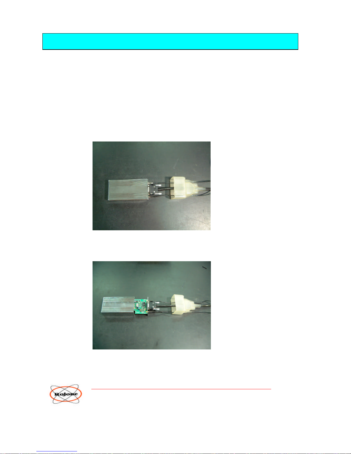
2. To access the Front Panel and remove the screws, simply cut the cable ties on the box and cable entry boots.
Place some silicon grease along the cable behind the 3 cable boots. Then carefully SLIDE the Inner plastic
boot back over the cables about 2 inches (50mm) to expose the front panel connectors.
Do NOT remove any connectors from the front panel.
Do NOT at any time remove the Rear Panel and attempt to remove the circuit board.
Check that the front panel cables and connectors are correctly mated and ensure that the Inner plastic boot is
sitting securely over the front panel and connectors.
3. Unscrew the 4 front panel screws and carefully slide out the main circuit board.
Page 21
ROJONE Pty. Ltd – 61 Aero Rd, INGLEBURN NSW 2565 AUSTRALIA
TEL +61 02 9829 1555 FAX 02 9605 8812 EMAIL [email protected]
20
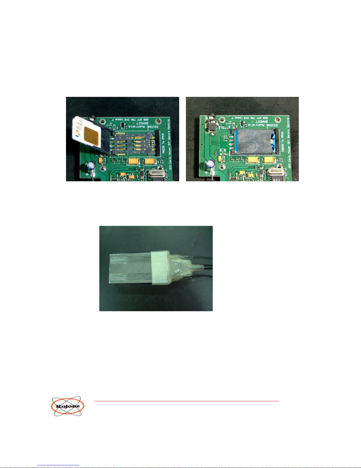
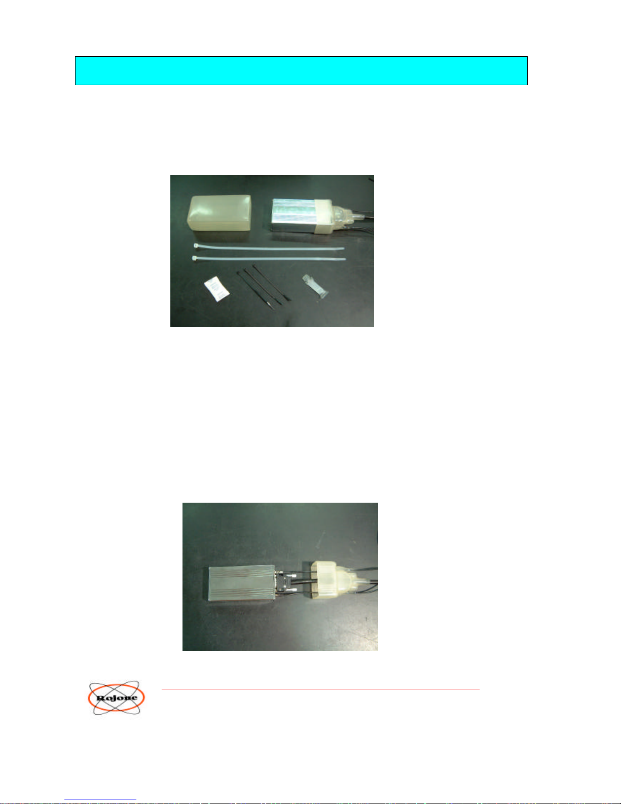
4. Locate the SIM Card holder and insert your SIM Card.
NOTE : Be sure to insert the SIM Card with the correct orientation.
IMPORTANT : Your EziTraK™ SIM Card should have the …
SIM Card PIN Number DISABLED
Re-Direction, Call Waiting, Message Bank etc DISABLED
ALL Automatic services should be DISABLED
5. Slide the main board back into the housing and replace the 4 front panel screws.
6. Carefully SLIDE the Inner plastic boot back over the housing.
7. Apply power to the unit.
8. Send the following SMS Message Commands to your EziTraK™ one at a time and wait for the SMS Message
response before sending the next one.
You should store commonly used SMS Commands in your phone for easy recall and resend.
The following example begins with the factory default PIN Number 1234.
The example first changes the PIN from 1234 to 8888. After this all commands must begin with the NEW PIN
Number 8888.
Page 22

ROJONE Pty. Ltd – 61 Aero Rd, INGLEBURN NSW 2565 AUSTRALIA
TEL +61 02 9829 1555 FAX 02 9605 8812 EMAIL [email protected]
21
EXAMPLE Setup commands …
1234.SET PIN.8888
8888.SET NAME.RGB555
8888.SET KILOMETRES
8888.REMOTE NUMBER.5556661111
8888.SMS NUMBER.5556662222
8888.EMERGENCY NUMBER.5557773333
8888.EMERGENCY SMS NUMBER.5557774444
8888.TOW AWAY OFF
8888.AUTO ARM OFF
8888.AUTO LOCK OFF
8888.ALARM OVERRIDE OFF
8888.SET OVERSPEED.120.KPH
8888.OVERSPEED DIALOUT ON
8888. BLACK BOX RATE.10
8888. START BLACK BOX
8888.SET LOW VOLTAGE.9
8888.GET SETTINGS
8888.GET STATUS
Page 23
ROJONE Pty. Ltd – 61 Aero Rd, INGLEBURN NSW 2565 AUSTRALIA
TEL +61 02 9829 1555 FAX 02 9605 8812 EMAIL [email protected]
22
8.0 APPENDIX B - Water Proofing Installation
WATER PROOFING
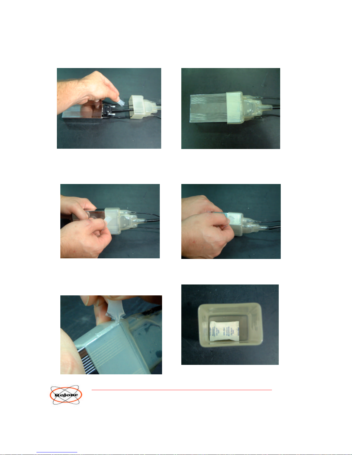
The water proofing supplied with the EziTraK™ kit consists of 2 plastic boots,
some silicon grease, cable ties and a water absorbing Desiccant Bag. The unit must NOT be immersed in water but
will survive a moist environment if properly installed and maintained.
The 2 plastic boots consist of an Inner plastic boot which covers the connector end of the unit and an Outer plastic boot
which covers the whole unit and overlaps ON TOP of the Inner plastic boot.
Once the SIM Card is inserted, the front panel screws replaced and the unit has been tested for correct operation, the
waterproofing can be installed.
Check the front panel cables and connectors are correctly mated and ensure that the Inner plastic boot is sitting securely
over the front panel and connectors.
To access the Front Panel and remove the screws, simply cut the cable ties on the box and cable entry boots. Place some
silicon grease along the cable behind the 3 cable boots. Then carefully SLIDE the Inner plastic boot back over the
cables about 2 inches (50mm) to expose the front panel connectors.
Page 24
ROJONE Pty. Ltd – 61 Aero Rd, INGLEBURN NSW 2565 AUSTRALIA
TEL +61 02 9829 1555 FAX 02 9605 8812 EMAIL [email protected]
23
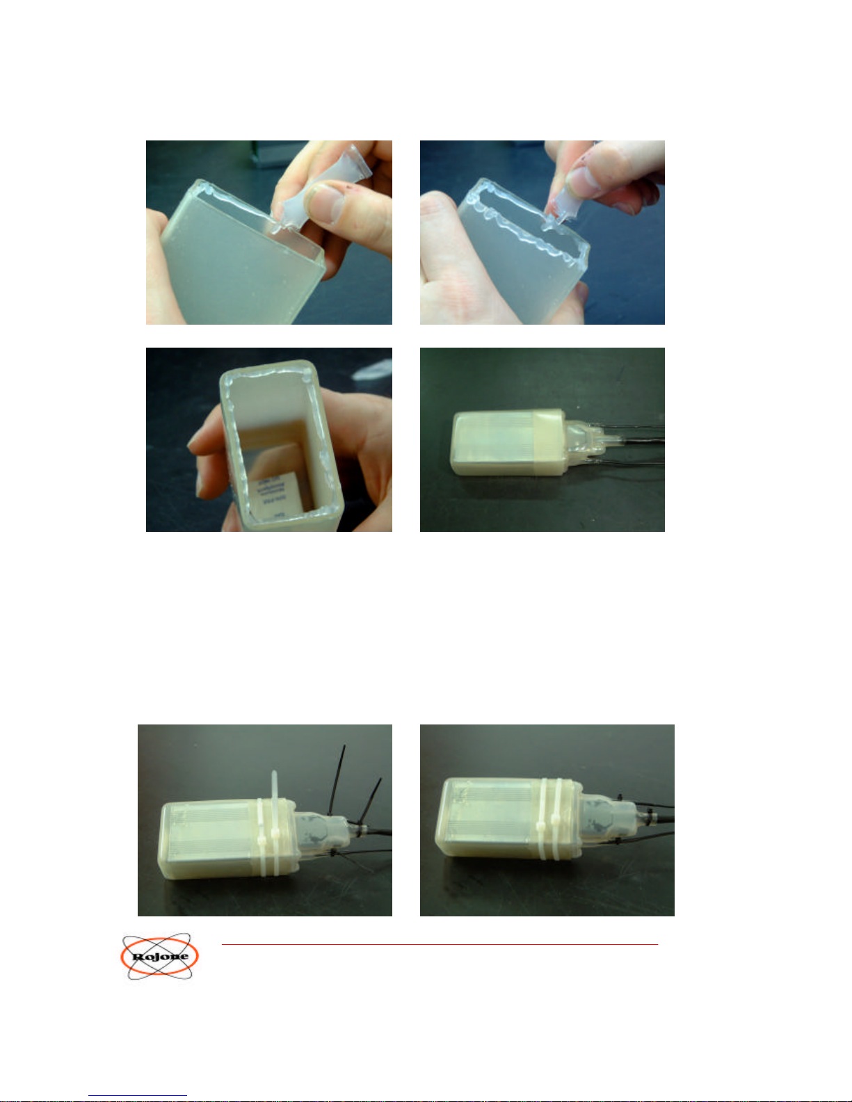
Do NOT at any time remove the Rear Panel and attempt to remove the circuit board.
Take the silicon grease sachet and apply a small amount to each of the cables just behind the connectors. This will allow
the Inner Plastic Boot to easily slide back over the connectors and is also needed to improve the waterproofing at the
cable entry into the Boot.
Carefully SLIDE the Inner plastic boot back over the housing and ensure that all connectors are properly mated. Take
the silicon grease and spread it evenly on the outside surface if the Inner plastic boot. That is around the 4 flat sides
covering the box.
Also spread the silicon grease liberally along all 4 edges.
Take the Outer plastic boot and place the water absorbing Desiccant Bag into the bottom of the boot.
Page 25
ROJONE Pty. Ltd – 61 Aero Rd, INGLEBURN NSW 2565 AUSTRALIA
TEL +61 02 9829 1555 FAX 02 9605 8812 EMAIL [email protected]
24
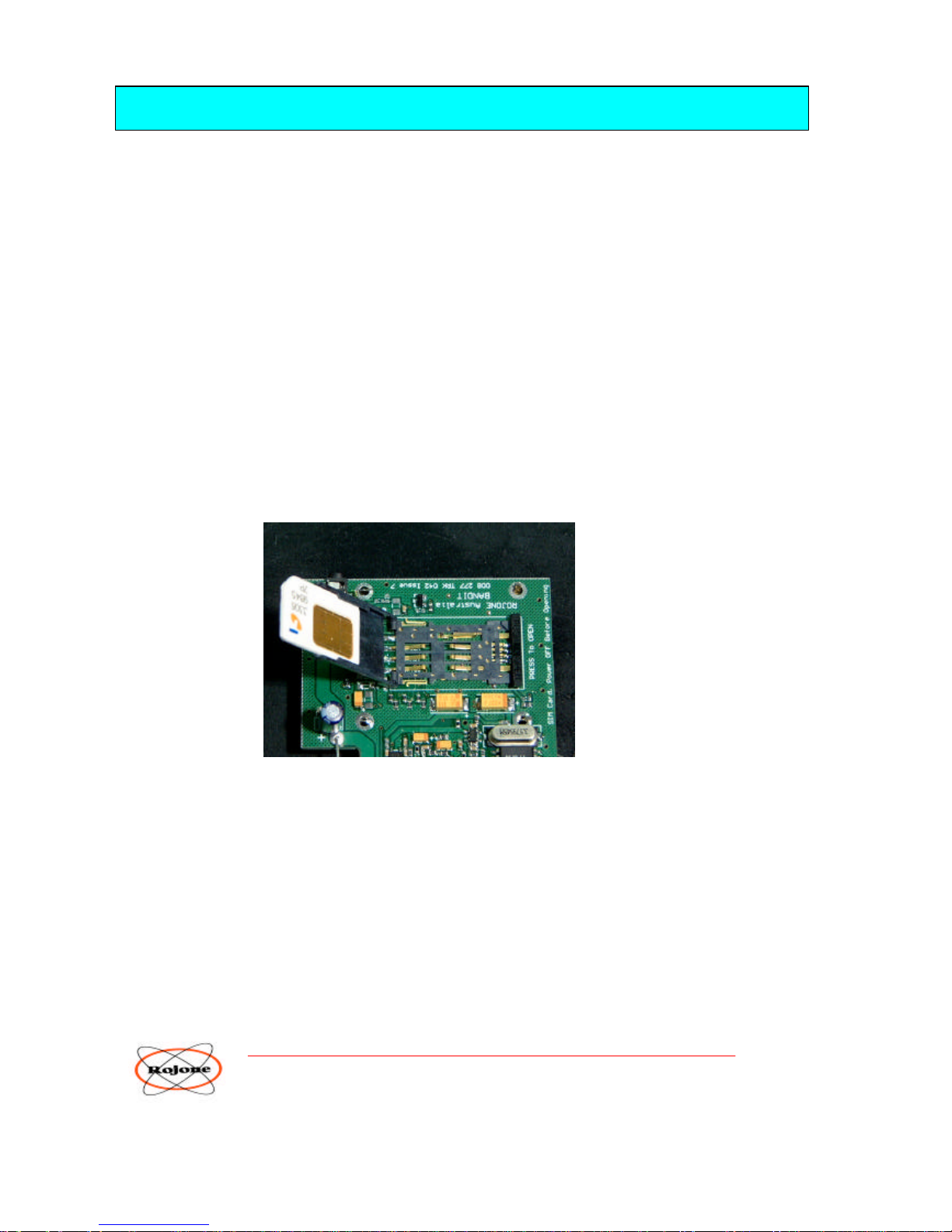
Apply silicon grease to the Outer Boot along the Inside Rim. The silicon grease should form a bead completely around
the top of the inside rim, particularly in the CORNERS. It is important for a good seal to have plenty of silicon grease
in the corners.
Slide the Outer plastic boot over the box and over the Inner plastic boot all the way until the Desiccant Bag comes in
contact with the Rear Panel.
The Outer plastic boot should now overlap the Inner plastic boot and the Silicon Grease should form a seal between the
2 boots.
Take the 2 large cables ties and carefully apply them around the overlapping boots and ensure that they are not over
tightened. The cable ties must NOT pinch the boot. Apply the 3 smaller cable ties to each of the cable entry boots, do
not over tighten. Cut and remove excess cable tie ends.
Page 26

ROJONE Pty. Ltd – 61 Aero Rd, INGLEBURN NSW 2565 AUSTRALIA
TEL +61 02 9829 1555 FAX 02 9605 8812 EMAIL [email protected]
25
Some silicon grease may be squeezed out of the gap between the 2 boots. Spread the excess evenly around the top edge
ensuring a good seal.
The water proofing is now complete.
IMPORTANT INFORMATION ON WATERPROOFING
NOT Fitting the Waterproofing
The waterproofing, when fitted, requires periodic maintenance to remove built up moisture from the sealed packaging.
So do NOT apply the waterproofing to the unit unless it is actually needed. Many installations are within a dry, benign
environment such as inside a vehicle or any other place that unprotected electronics are mounted.
NOT fitting the waterproofing simply means NOT fitting the Outer Plastic Boot. Leave the Outer Plastic Boot off to
allow the unit to breathe natural air.
Fitting the Waterproofing
The waterproofing, when applied, is for moist environments only where water may come in contact with the unit in a
NON continuous splash at atmospheric pressure only.
The unit must NOT be immersed in water, to any depth, but will survive a moist environment if properly
installed and maintained.
Pressurised water must NOT be sprayed directly at the unit at any time.
Do NOT expose the unit to direct sunlight or high temperatures, particularly in moist environments.
Check the unit regularly for water ingress as part of your normal maintenance. The Desiccant Bag will remove most of
the moisture from within the unit. It is important that the Desiccant Bag is periodically replaced, which depends on
humidity and local moisture level.
NOTE : If the unit is in a very wet environment it is preferable to use a Silicon Sealant INSTEAD of the Silicon
Grease to seal the overlap of the 2 BOOTS. A single bead of sealant is only needed around the top opening of the
boot. This will need to be removable for maintenance.
Adding Conformal Tape will also improve the seal. NOTE : Remove all Silicon Grease before applying Silicon
Sealant. Silicon Sealant should also be applied to all exposed cables, electrical terminals and connectors. Do NOT
apply Silicon Sealant to the Cable Boot Exits.
Page 27
ROJONE Pty. Ltd – 61 Aero Rd, INGLEBURN NSW 2565 AUSTRALIA
TEL +61 02 9829 1555 FAX 02 9605 8812 EMAIL [email protected]
26
9.0 APPENDIX C - RESET Procedure
If you lose your PIN Number and are unable to access your EziTraK™ then you will need to RESET your unit back to
the Factory Defaults including PIN Number 1234 #.
To do this repeat the first 3 steps in the Setup Procedure – Appendix A.
1. Remove all power from the unit including the backup battery.
2. To access the Front Panel and remove the screws, simply cut the cable ties on the box and cable entry
boots. Place some silicon grease along the cable behind the 3 cable boots. Then carefully SLIDE the Inner plastic boot
back over the cables about 2 inches (50mm) to expose the front panel connectors.
Do NOT remove any connectors from the front panel.
Do NOT at any time remove the Rear Panel and attempt to remove the circuit board.
Check that the front panel cables and connectors are correctly mated and ensure that the Inner plastic boot is
sitting securely over the front panel and connectors.
3. Unscrew the 4 front panel screws and carefully slide out the main circuit board.
THEN …
4. Locate the SIM Card holder and REMOVE your SIM Card.
5. Power UP the EziTraK™ Unit and wait a few minutes.
6. Power DOWN the EziTraK™ and Re-Insert your SIM Card.
7. Replace the Front Panel screws and the Waterproofing.
8. Your EziTraK™ should now be reset and you can gain access using the Default PIN 1234 #. You should now
use the example SMS Setup Command List to setup your EziTraK™ preferences and Phone Numbers. See
Appendix A.
Page 28

ROJONE Pty. Ltd – 61 Aero Rd, INGLEBURN NSW 2565 AUSTRALIA
TEL +61 02 9829 1555 FAX 02 9605 8812 EMAIL [email protected]
27
10.0 APPENDIX D - Contents of EziTraK™ Kit
ITEM QTY DESCRIPTION
A. 1 x Plastic Carry Case + Glossy Cover
B. 1 x EziTraK™ PVM Unit
C. 1 x GPS Antenna with cable, (3 Volt)
D. 1 x GPS Antenna Cable and MCX Male to MCX Female
E. 1 x Cellular GSM Antenna
F. 1 x Cellular Antenna Cable SMA Male to SMA Male
G. 1 x Cable Loom (~ 1.5 metres with 9 Pin Male D-Sub, Colored wires, Female Spades)
H. 1 x Panic Button with cable and Male Spade connectors. (Normally Open Contacts)
I. 12 x Male Spade connectors (Crimp Type)
J. 12 x Female Spade connectors (Crimp Type)
K. 3 x Automotive Relays
L. 1 x CD Containing
- Technical Manual (User Guide and Installation)
- User Guide Video
- Installation Video
- EziTraK ON-Line PC Application Program
M. 1 x Waterproofing Kit
- 2 Rubber Boots
- 7 Cable Ties (2 Large, 3 Small, + Spares)
- Silicon Grease
- Desicant Bag
N. 1 x Printed Manual and List Of Contents (This List)
Please NOTE : Items O. and P. are not shipped in the kit when exported to overseas countries due to
Laws regarding the transportation and importation of batteries.
Local distributors may or may not source and supply equivalent product for inclusion into the kit.
Alternatively an equivalent product may be supplied by the installer.
O. 1 x Backup Battery
Sealed Lead Acid Rechargeable
Manufacturer CGB or equivalent
P/N CB1207 12V 0.7AH
P. 1 x Optional Backup Battery Bracket.
R. 1 x Optional DPDT FOB Relay OR DPST FOB Switch OR RF FOB Controller.
Page 29

ROJONE Pty. Ltd – 61 Aero Rd, INGLEBURN NSW 2565 AUSTRALIA
TEL +61 02 9829 1555 FAX 02 9605 8812 EMAIL [email protected]
28
11.0 APPENDIX E - DISCLAIM ER - PLEASE READ CAREFULLY
This manual is provided as a guide to the typical use of the EziTraK™ . The EziTraK ™ accuracy and intercept can be
affected by many factors including environmental conditions, general poor signal strength, equipment failure, defects
and improper handling / use. It is the user’s responsibility to exercise common prudence and judgement. This device
should in no way be relied upon as a substitute for such prudence and judgment. Your EziTraK™ is also subject to the
coverage of your own Network Service Provider.
HOWEVER, ROJONE ACCEPTS NO RESPONSIBILITY WHATSOEVER FOR ANY ACTIONS ON THE PART
OF THE PURCHASER OR USER WHICH MAY RENDER THE EQUIPMENT INOPERATIVE DUE TO ANY
FAILURE ON THE PART OF THE PURCHASER OR USER TO COMPLY WITH THE "'OWNERS MANUAL"'
AND STRICTLY IN ACCORDANCE WITH THE DIRECTIONS AND GUIDELINES NOTED THEREIN.
FURTHER, ROJONE ACCEPTS NO RESPONSIBILITY FOR ANY CONSEQUENTIAL EFFECTS OR
BREACHES RESULTING FROM THE PURCHASER OR USER'S FAILURE TO USE THE EQUIPMENT FOR
THE PURPOSE FOR WHICH IT IS INTENDED INCLUDING ANY BREACHES OF THE PRIVACY ACT, THE
CRIMES ACT 1900, THE WORKPLACE SURVEILLANCE ACT 1998 (NSW), THE INDUSTRIAL RELATIONS
ACT 1996 OR LEGISLATION, THE PASSENGER TRANSPORT (TAXI CAB SERVICES) ACT 1995, THE
COMMON LAW AND ANY AND ALL LEGISLATION DEALING WITH PRIVACY AND SURVEILLANCE OF
PERSONS INCLUDING EMPLOYEES.
IN ADDITION, ROJONE DISCLOSES THAT THE IMPROPER USE OF THE EQUIPMENT MAY CONTRAVENE
PARTS OF THE LEGISLATION REFERRED TO IN THE PREVIOUS PARAGRAPH. ACCORDINGLY, ROJONE
ACCEPTS ABSOLUTELY NO RESPONSIBILITY FOR USAGE WHICH MAY FALL OUTSIDE OF THE SCOPE
OF THE PROPER INTENDED PURPOSE OF THE EQUIPMENT.
ROJONE ALSO DISCLOSES THAT THE IMMOBILIZATION CAPACITY OF THE EQUIPMENT MAY RESULT
IN DAMAGE, HARM AND OR PERSONAL INJURY TO THE DRIVER OF THE VESSEL AND ITS
PASSENGERS PARTICULARLY WHERE THE IMMOBILIZATION OCCURS AT A SIGNIFICANT SPEED.
ROJONE ACCEPTS NO LIABILITY OR RESPONSIBILITY FOR ANY RESULTING DAMAGE, HARM OR
PERSONAL INJURY CAUSED OR SUSTAINED BY PERSONS IN SUCH CIRCUMSTANCES.
PURCHASERS OF THE EQUIPMENT ARE CAUTIONED TO USE THE EQUIPMENT EXERCISING
DILIGENCE AND CARE AT ALL TIMES. ROJONE ACCEPTS NO RESPONSIBILITY FOR ANY FAILURE OF
THE PURCHASER OR USER'S DUTY OF CARE RESULTING FROM ANY IMPROPER OR UNAUTHORISED
OR WRONGFUL USE OF THE EQUIPMENT.
NO LIABILITY FOR CONSEQUENTIAL DAMAGE; IN NO EVENT ROJONE OR THEIR
RESPECTIVE REPRESENTATIVES BE LIABLE FOR ANY DAMAGES WHAT SOEVER
(INCLUDING DIRECT OR CONSEQUENTIAL INJURY, LOSS OR DAMAGE , OR ANY
PECUNIARY LOSS) INCURRED THROUGH THE USE, OR THE INABILITY TO USE, OR
IMPROPER USE OF THE EziTraK™ PRODUCT.
Rojone reserves the right to make design changes to any Rojone product without incurring any
obligation to make the same changes to previously purchased units.
Page 30

ROJONE Pty. Ltd – 61 Aero Rd, INGLEBURN NSW 2565 AUSTRALIA
TEL +61 02 9829 1555 FAX 02 9605 8812 EMAIL [email protected]
29
This product is designed and manufactured in Australia.
ROJONE Contact Details :
Head Office 61 Aero Road,
Ingleburn NSW 2565
Sydney Australia
EMAIL : [email protected]
TELEPHONE : 02 9829 1555 Intl : 612 9829 1555
FACSIMILE : 02 9605 8812 Intl : 612 9605 8812
Copyright 2001 All rights are reserved. No part of this publication is to be reproduced in any
form or by any means without the express permission of the management of Rojone Pty. Limited –
Australia.
The EziTraK™ is a registered Trade Mark of Rojone Pty. Limited and may not be used without the
express permission of it’s owner.
Rojone reserves the right to change the information contained in this document without notice.
www.rojone.com.au / [email protected]
Page 31

ROJONE Pty. Ltd – 61 Aero Rd, INGLEBURN NSW 2565 AUSTRALIA
TEL +61 02 9829 1555 FAX 02 9605 8812 EMAIL [email protected]
30
12.0 APPENDIX F - WARRANTY
Your EziTraK™ is warranted for a period of 12 months against defects in material & workmanship’s
EFFECTIVE FROM DATE OF PURCHASE.
Please complete the enclosed warranty card to secure your Guarantee and kindly retain your
Purchase receipt as proof of purchase, which must be presented if making a claim under the terms of the
Rojone Guarantee.
LIMITATION OF LIABILITY, DISCLAIMERS AND PRIVACY ISSUES.
ROJONE WARRANTS THAT IT HAS USED ITS BEST ENDEAVOURS TO MANUFACTURE A
PRODUCT FOR THE PURPOSE FOR WHICH IT IS INTENDED USING ITS KNOWLEDGE KNOW
HOW, EXPERTISE AND SKILL.
HOWEVER, ROJONE ACCEPTS NO RESPONSIBILITY WHATSOEVER FOR ANY ACTIONS ON THE
PART OF THE PURCHASER OR USER WHICH MAY RENDER THE EQUIPMENT INOPERATIVE
DUE TO ANY FAILURE ON THE PART OF THE PURCHASER OR USER TO COMPLY WITH THE
"'OWNERS MANUAL"' AND STRICTLY IN ACCORDANCE WITH THE DIRECTIONS AND
GUIDELINES NOTED THEREIN.
FURTHER, ROJONE ACCEPTS NO RESPONSIBILITY FOR ANY CONSEQUENTIAL EFFECTS OR
BREACHES RESULTING FROM THE PURCHASER OR USER'S FAILURE TO USE THE EQUIPMENT
FOR THE PURPOSE FOR WHICH IT IS INTENDED INCLUDING ANY BREACHES OF THE PRIVACY
ACT, THE CRIMES ACT 1900, THE WORKPLACE SURVEILLANCE ACT 1998 (NSW), THE
INDUSTRIAL RELATIONS ACT 1996 OR LEGISLATION, THE PASSENGER TRANSPORT (TAXI CAB
SERVICES) ACT 1995, THE COMMON LAW AND ANY AND ALL LEGISLATION DEALING WITH
PRIVACY AND SURVEILLANCE OF PERSONS INCLUDING EMPLOYEES.
IN ADDITION, ROJONE DISCLOSES THAT THE IMPROPER USE OF THE EQUIPMENT MAY
CONTRAVENE PARTS OF THE LEGISLATION REFERRED TO IN THE PREVIOUS PARAGRAPH.
ACCORDINGLY, ROJONE ACCEPTS ABSOLUTELY NO RESPONSIBILITY FOR USAGE WHICH
MAY FALL OUTSIDE OF THE SCOPE OF THE PROPER INTENDED PURPOSE OF THE EQUIPMENT.
ROJONE ALSO DISCLOSES THAT THE IMMOBILIZATION CAPACITY OF THE EQUIPMENT MAY
RESULT IN DAMAGE, HARM AND OR PERSONAL INJURY TO THE DRIVER OF THE VESSEL AND
ITS PASSENGERS PARTICULARLY WHERE THE IMMOBILIZATION OCCURS AT A SIGNIFICANT
SPEED. ROJONE ACCEPTS NO LIABILITY OR RESPONSIBILITY FOR ANY RESULTING DAMAGE,
HARM OR PERSONAL INJURY CAUSED OR SUSTAINED BY PERSONS IN SUCH
CIRCUMSTANCES.
PURCHASERS OF THE EQUIPMENT ARE CAUTIONED TO USE THE EQUIPMENT EXERCISING
DILIGENCE AND CARE AT ALL TIMES. ROJONE ACCEPTS NO RESPONSIBILITY FOR ANY
FAILURE OF THE PURCHASER OR USER'S DUTY OF CARE RESULTING FROM ANY IMPROPER
OR UNAUTHORISED OR WRONGFUL USE OF THE EQUIPMENT.
Nothing in these terms shall exclude, restrict or modify any conditions, warranty or liability implied into this
contact by statute. WHERE to do so would be unlawful or would render any provision of this contract void.
Subject to that, all warranties implied by statute in respect of the goods are hereby expressly negated, and
Rojone's liability for the goods is limited to any warranties issued in writing by Rojone. Rojone is excluded
from any other liability whether under this contract or otherwise to the buyer or any third party for any loss,
injury, cost or damage incurred or suffered by reason of the goods, their use, or their design. Whether direct,
indirect, special consequential or otherwise and whether or not arising from a negligent act or omission of
Rojone.
Page 32

ROJONE Pty. Ltd – 61 Aero Rd, INGLEBURN NSW 2565 AUSTRALIA
TEL +61 02 9829 1555 FAX 02 9605 8812 EMAIL [email protected]
31
Where it is legal to do so, any remaining liability implied by statue or resulting from breach of any term,
condition, warranty implied or statute is limited to Rojone's sole option.
These options are as follows:
(i) The replacement of the goods
(ii) The repair of goods
(iii) The payment of the cost of replacing the goods.
(iv) The payment of the cost of having the goods repaired.
The buyer should be aware that in relation to goods which are of a kind ordinarily acquired for personal use or
consumption, certain statutory provisions such as the Trade Practice Act 1974 which are not excludable, may
render Rojone liable to greater extent than provided in the clause. These terms do not exclude rights and
remedies implied by a statute, which are non-excludable.
Please contact the factory for further information or our Website www.rojone.com.au
END OF DOCUMENT …
 Loading...