

Rointe KYROS Installation Manual
KYROS
Digital Electric Water Heater
Wall-hung Unvented
INSTALLATION
MANUAL

02

03
WELCOME
Dear Customer,
Thank you for choosing the KYROS electric water heater, with an exclusive electronic temperature
programmer and made with the highest quality materials.
The KYROS water heaters have exceeded the most stringent quality controls in order to comply with the
most rigorous requirements for safety.
Thanks to its exclusive ROINTE Fuzzy Logic Energy Control technology, the electric water heater
achieves the maximum energy saving.
Before using the electric water heater we recommend you read this manual carefully in order to obtain
proper operating information.
IMPORTANT
THIS MANUAL SHOULD BE LEFT WITH THE UNIT AFTER INSTALLATION

04
TABLE OF CONTENTS
1. Introduction ....................................................................................................................................... 05
2. Technical Specifications ................................................................................................................... 05
3. General Requirements ...................................................................................................................... 06
4. Plumbing Installation ........................................................................................................................ 07
5. Electrical Installation ........................................................................................................................ 11
6. Filling and Commissioning ............................................................................................................... 12
7. Servicing and Maintenance ............................................................................................................... 12
8. Fault Finding ..................................................................................................................................... 13
9. User Instructions .............................................................................................................................. 14
10. Guarantee .......................................................................................................................................... 19
11. Installation, Commissioning and Service Record ............................................................................ 21
05
1. INTRODUCTION
The “RD TFT Series” is a high quality unvented enamelled steel domestic hot water cylinder suitable for
domestic hot water systems where the cold mains water supply has a maximum supply pressure of 0.9
MPa. Reduced performance is available at lower pressures but the units are not suitable for pressures
lower than 0.15 MPa and flow rate of 20 litres per minute.
Rointe offers the possibility to acquire all the necessary safety equipment to comply with legislation
governing the installation of such systems.
2. TECHNICAL SPECIFICATIONS
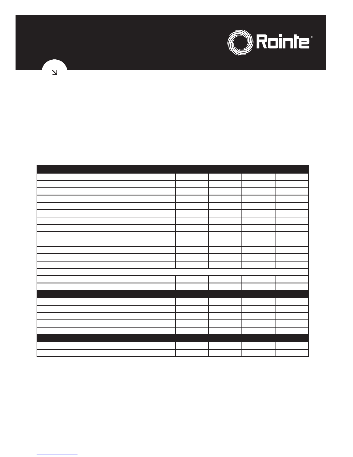
TECHNICAL SPECIFICATIONS
MODEL NUMBER
KWI050DHW2 KWI075DHW2 KWI100DHW2 KWI150DHW2 KWI200DHW2
Storage capacity (l) 50 75 100 150 200
Power (W) 2,400 2,400 2,400 2,400 2,400
Depth (mm) 404 404 404
580 580
Width (mm) 404 404 404 580 580
Overall height incl T/P valve 785 1,035 1,270 1,160 1,220
Height excl T/P valve 685 935 1,170 960 1,120
Weight when full (kg) 68 100 132 194 256
Cold feed/hot draw off connections (mm) 15 15 15 22 22
Maximum water supply pressure (MPa) 0.9 0.9 0.9 0.9 0.9
System operating pressure (pre-set) (MPa) 0.6 0.6 0.6 0.6 0.6
Expansion vessel charge pressure (MPa) 0.15 0.15 0.3 0.3 0.3
Expansion relief valve set pressure (MPa) 0.6 0.6 0.6 0.6 0.6
Temperature and pressure relief valve settings:
Lift pressure (MPa) 0.7 0.7 0.7 0.7 0.7
Lift temperature (ºC) 90 90 90 90 90
INSTALLATION KIT (OPTIONAL)
0.3 MPa pressure reducing valve • • • • •
0.6 MPa expansion relief valve • • • • •
Expansion vessel ltr 8 8 12 12 18
15mm to 22mm Tundish • • • • •
Isolation valve • • • • •
PERFORMANCE
Heat up time 15 to 65 ºC (min) 73 110 117 175 235
Reheat time for 70% of contents (min) 51 77 82 123 165
2.1. Component Check List
The KYROS water heater comes with the following components, please check through the
components supplied and ensure that all parts are present:
• Water Heater with sheathed heating elements, digital thermostat, TFT screen and manual
reset thermal cut-out
• T/P valve 0.7 MPa 90ºC and electrolytic fittings
• Installation and user manual
Please contact our customer service department to know how to acquire the safety fittings.
06
3. GENERAL REQUIREMENTS
3.1. The KYROS domestic hot water cylinder MUST be installed by a competent person in accordance
with section G3 of the current Building Regulations.
3.2. Important - It is important that the installer reads and understands these instructions, unpacks
and familiarises themselves with the equipment before commencing the installation. Failure to
observe these installation instructions could invalidate the warranty.
3.3. Water supply – The water supply to the cylinder should be potable water direct from a public
mains water supply with any water treatment equipment functioning correctly.
For optimum performance the unit should be fed via a 15 mm or 22 mm diameter supply pipe direct
from the mains water entry point to the property with supplies a maximum pressure of 0.9 MPa.
The unit can operate with a minimum supply pressure of 0.15 MPa and a flow rate of at least 20
litres per minute, but flow from the outlets will be low if several outlets are used simultaneously.
The cylinder control equipment is factory set to limit the system operating pressure to 0.3 MPa. The
maximum supply pressure into the pressure-reducing valve is 0.9 MPa.
3.4. Taps and fittings - All taps and fittings incorporated in the unvented system should have a
rated operating pressure of 0.7 MPa or above.
3.5. Location – The unit is designed to be vertically wall mounted, indoors, in a frost-free
environment. When choosing a suitable location for the cylinder, consideration should be given
to the routing of the discharge pipe to a convenient point and also the availability of an adequate
power supply for connecting the sheathed heating elements.
The wall onto which the cylinder is mounted should
be of good sound masonry construction capable of
holding the weight of the cylinder when full of water
(see
technical specifications
for weights).
The position of the cylinder should be such that easy
access is provided for servicing the controls and
replacing the sheathed heating element should the
need arise.
Pipe runs should be made as short as possible and
lagged to prevent heat loss.
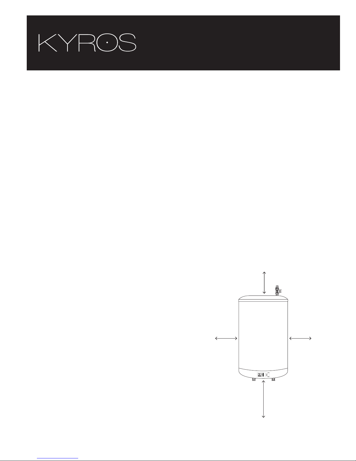
To allow for servicing and repairs the unit must be
mounted at least 540 mm above any surface or object,
so that access can be gained to electric connectors
and the heating elements may be removed (see Fig 1).
The unit should be mounted close to an external wall
so that the discharge pipe D2 can be routed to a safe
visible place.
The tundish should be mounted in a visible location so
that it may easily be inspected.
Fig 1 - Minimum margins for servicing and repairs.
150 mm
100 mm 100 mm
540 mm
07
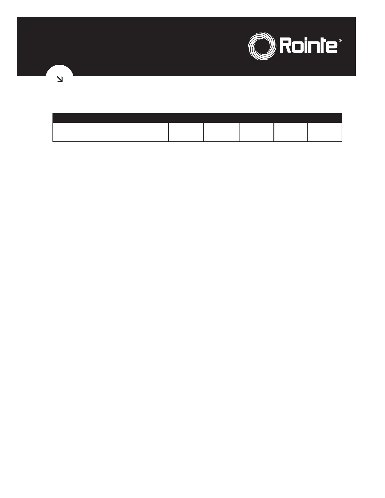
The distance between holes for the wall mounting depends on the model, see the following table
for reference:
Model
KWI050DHW2 KWI075DHW2 KWI100DHW2 KWI150DHW2 KWI200DHW2
Horizontal width between holes 350 mm 350 mm 350 mm 350 mm 350 mm
Height between upper and lower holes 340 mm 573 mm 768 mm 490 mm 670 mm
3.6. Storage and handling – If the cylinder is not being installed immediately, it should remain in its
box with all pipe end protective caps in situ to prevent damage. We recommend that the cylinder be
transported to its installation position with the outer box in place.
3.7. Pipework connections – All pipework connections to the cylinder MUST be made in accordance
with Fig 2.
3.8. Safety – This product is not intended to be used by persons (including children) with reduced
physical, sensory, or mental capacities, or have no experience or knowledge of the product, except if
they are supervised or instructed in the use of the product by a person who is responsible for his or
her safety. Children must be supervised at all times to ensure that they do not play with the product.
4. PLUMBING INSTALLATION
4.1. Connections. Connections MUST be made to the cylinder in accordance with Fig 1, and Fig 2.
A drain cock (not supplied) should be fitted in the position shown in Fig 2 to facilitate draining of
the cylinder.
4.2. Electrolytic fittings – It is a must for the electrolytic fittings to be fitted with the water heater.
If not, the guarantee will be void. Check the T/P Valve to see if it is connected with the electrolytic
fittings . If not, please contact us.
4.3. Cold water supply – For best results, the cylinder should be fed by an uninterrupted supply
pipe into the pressure reducing valve (PRV) with a maximum supply pressure of 0.9 MPa. The
cylinder should not be used on any system with a supply pressure below 0.15 MPa and a flow rate
of less than 20 litres per minute.
4.4. Temperature and pressure relief valve – The temperature and pressure relief valve (T/P Valve)
is supplied. Once the T/P valve is fitted should not be removed from the cylinder or tampered with
in any way. The valve is pre calibrated to lift at 0.7 MPa or 90 degrees centigrade and any attempt to
adjust it will invalidate the warranty and could affect the safety performance of the unit.
The outlet of the T/P valve should be routed in 15 mm copper piping in a downward direction
alongside the water heating unit to the tundish in a frost-free environment. The outlet of the
expansion relief valve must be T’d into this pipe before the tundish so that any water exiting either
valve can be seen draining through the tundish– see figure 2 and 3.
4.5. Pressure reducing valve – The pressure reducing valve should be installed in the cold water
supply to the water heating unit with the arrow pointing in the direction of water flow as shown in
figure 2. This can be connected to a maximum supply pressure of 0.9 MPa.
4.6. Expansion relief valve – This must be installed between the pressure reducing valve and the
water heating unit in accordance with Figure 2. No other valve should be fitted between this valve
and the cylinder. The expansion relief valve contains a non return valve.
08
4.7. Expansion vessel – A suitable expansion vessel with a pre-charge pressure of 0.15 or 0.3 MPa
is available in an optional kit for fitting to all water heating units in the range. The expansion vessel
MUST be fitted to the safety group. The expansion vessel MUST be positioned with the entry point
at the bottom – see Figure 2.
IMPORTANT: Regular checks must be carried out to ensure that the expansion vessel is correctly
pressurised to 0.15 or 0.3 MPa at all times. – see Figure 2.
4.8. Tundish – The tundish must not be positioned above or in close proximity of any electrical
current carrying devices or wiring. The installation should conform with the requirements of item
4.10 below.
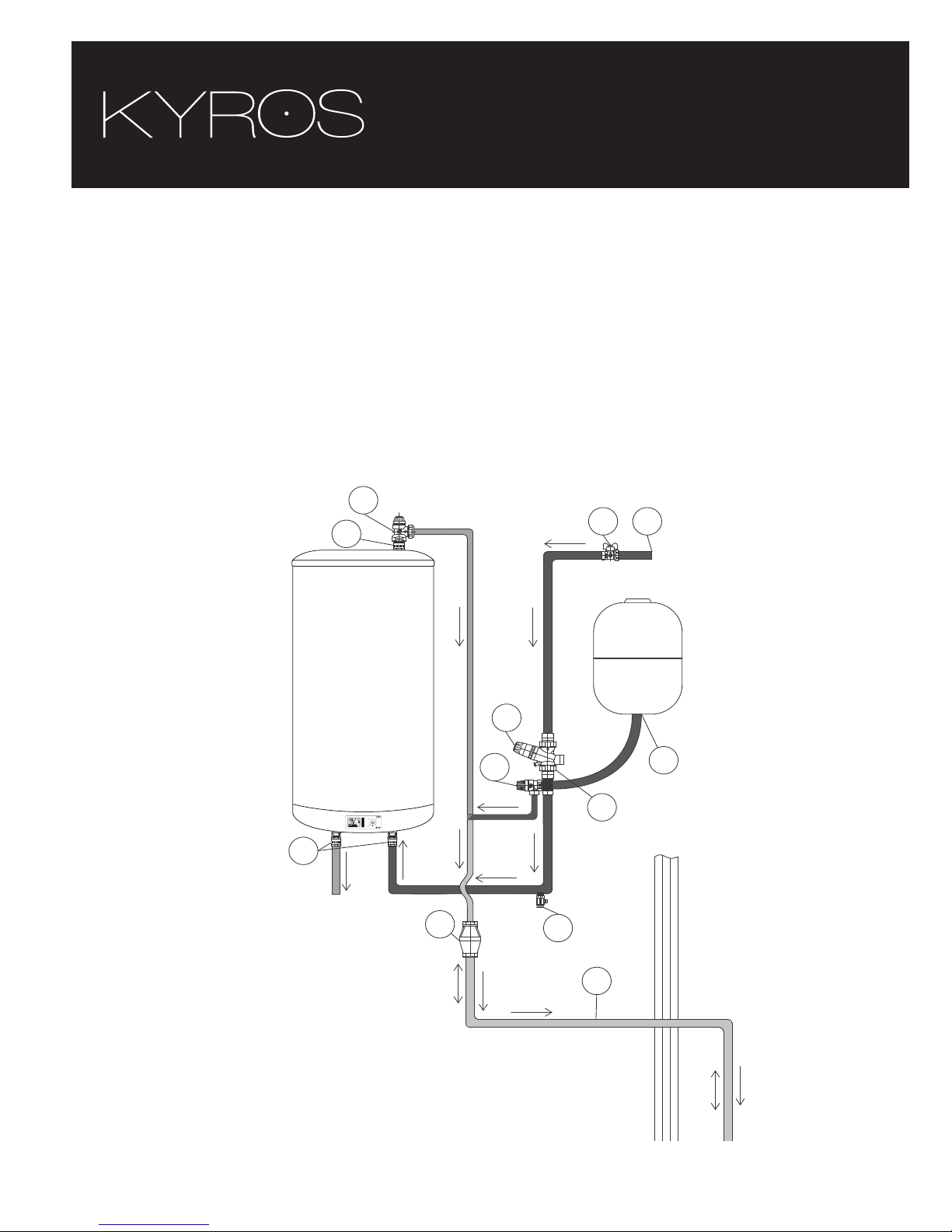
4.9. Connection arrangement for TFT KYROS Cylinder
Water Flow
To tap
CW
to tap
Cold
water
inlet
Hot water
Outlet
12
5
3
4
300 MIN
100 MAX
6
9
8
7
10
11
11
1 Mains cold water supply
2 Stop cock (not supplied)
3 Pressure reducing valve *
4 Check valve *
5 Expansion relief valve *
6 Discharge pipe 22 mm
7 Drain cock (not supplied)
8 Tundish *
9 Expansion vessel *
10 T/P relief valve (included)
11 Electrolytic fittings (included)
Figure 2
* Available in optional Installation Kit
 Loading...