

Rointe DALIS Series, Dalis 200DHW4, Dalis 200DHWI4, Dalis 260DHW4, Dalis 260DHWI4 Instruction Manual
INSTRUCTION MANUAL
Information, operation & installation
DALIS
Digital electric unvented heat pump

Please read this instruction manual carefully to ensure correct installation and operation.
It is important that the installer reads and understands these instructions and unpacks and
familiarises themselves with the equipment before commencing the installation. Failure to
observe these instructions will make the guarantee invalid.
CONTENTS
1. Introduction ....................................................................................................................................... 2
2. Disclaimer ......................................................................................................................................... 3
3. Regulations ....................................................................................................................................... 3
4. Mandatory installation kits ............................................................................................................... 3
5. Safety information and warnings ..................................................................................................... 4
6. Technical information ....................................................................................................................... 6
7. Before installation ............................................................................................................................. 8
8. Installation ....................................................................................................................................... 12
9. Commissioning ............................................................................................................................... 24
10. Programming ................................................................................................................................. 25
11. Maintenance .................................................................................................................................. 39
12. Troubleshooting ..............................................................................................................................41
13. Product disposal .............................................................................................................................41
14. Guarantee conditions .................................................................................................................... 42
15. Commissioning record .................................................................................................................. 44
16. Guarantee certificate ..................................................................................................................... 45
17. Service record ............................................................................................................................... 47
1. Introduction
Thank you for choosing Rointe. The Dalis heat pump is designed to produce sanitary domestic hot
water, through the use of heat pump technology. This model consists of a compressor, evaporator,
condenser and a throttle valve. A liquid / refrigerant gas flows inside this product.
The product is manufactured from high quality components and meets all health and safety require-
ments. Before installing and / or using this product, carefully read this manual. This manual must be
kept with the product at all times, even if the ownership of the product changes.
If you have any questions on this product, please contact our Technical Support department by phon-
ing 0203 321 5929 or send an email to support@rointe.co.uk.
IMPORTANT: This product has been manufactured for domestic hot water as part of a pressur-
ised water heating system. Rointe will not take responsibility for safe operation of this product
outside of the scope of intended use.
The symbol represents important information or a warning. Please read these carefully.
2

DALIS
Digital electric unvented heat pump
2. Disclaimer
This manual has been thoroughly verified, however in some instances non-compliance can occur.
Therefore we (Rointe) accept no liability for complete conformity.
We reserve the right to carry out modifications to the product’s construction, characteristics or its
data at any time. Therefore, we do not accept any liability claims attributable to instructions, figures,
drawings or descriptions, without prejudice to errors of any kind.
We will not be held responsible for damages attributable to incorrect installation, product misuse or
improper use, or as a consequence of unauthorised repairs, modifications or replacement.
3. Regulations
The equipment can only be installed and commissioned for use within domestic water closed heating
systems, according to the BS EN 12828 standard. It adheres to the following directives:
• Directive 2011/65/UE on use of hazardous substances in electronic equipment (RoHS).
• Directive 2014/30/UE Electromagnetic compatibility (EMC).
• Directive 2014/35/EU Low Voltage Directive (LVD).
• Directive 2009/125/CE Ecodesign requirements.
• Directive 2010/30/UE Energy labelling.
• Directive 2012/19/UE on waste electrical and electronic equipment (WEEE).
3.1. Protection degree
The product has a Protection Degree of IPX4.
3.2. Refrigerant/coolant used
The type of refrigerant used is: HFC-R134a. This device contains fluorinated greenhouse gases
included in the Kyoto protocol. Do not discard these gases into the environment. Maintenance and
disposal operations must be carried out by qualified personnel only.
4. Mandatory installation kits
IMPORTANT
As this product is an unvented domestic hot water heater, it is mandatory that it be
installed using a Rointe installation kit and by a professional with a valid Unvented
Water Heater Installer certification. The installation kits are NOT supplied with this
product. They must be purchased separately. They comply with Building Regulations
Section G3.
Please contact us on 0203 321 5929 if you have not purchased an appropriate
installation kit for this product BEFORE installation.
The T/P valve is factory fitted with the product as standard.
3
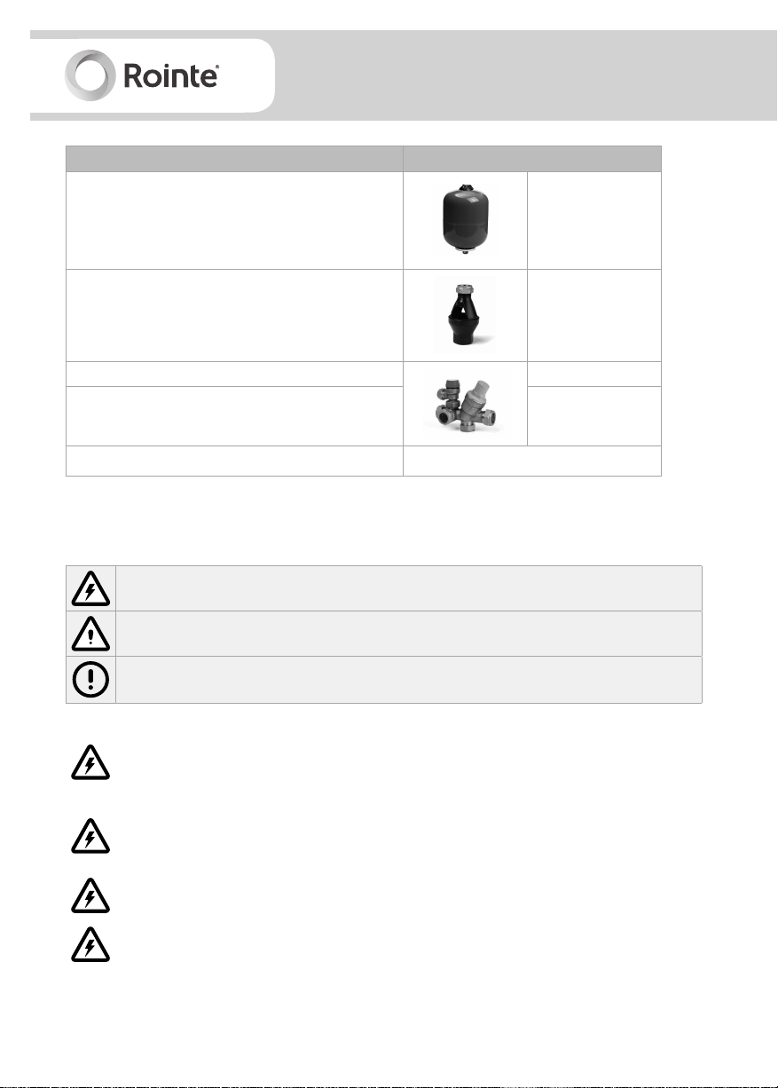
Fittings supplied with installation kit (sold separately) KITW03
Expansion vessel
Tundish 15 - 22 mm
Pressure reducing valve 0.35 Mpa
Safety relief valve 0.60 Mpa
EAN CODE 8436045914354
18 litres
(0.1 Mpa)
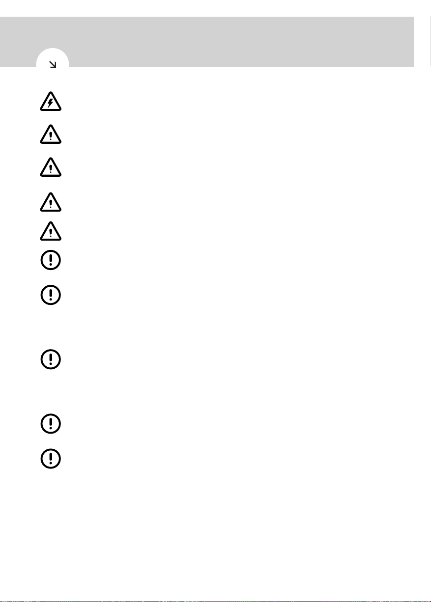
5. Safety information and warnings
Please read this information carefully. If you have any questions, please contact us.
This symbol indicates a safety warning or a hazard of an electrical nature.
This symbol indicates general warnings of actions that could result in damage to the
product or injury to the installer/user/person.
This symbol indicates information or advice for operation of the product.
Do not open or disassemble the product when it is connected to a power supply. Isolate
all electrical supplies from the product before commencing work. Danger of electric
shock!
The maintenance of this appliance must be carried out by suitable qualified persons
only. It is recommended to maintain the product on an annual basis. Isolate all power
supplies from the product before commencing work. Danger of electric shock!
It is important that the tundish is positioned away from any electrical components.
Means for electrical disconnection must be incorporated in the fixed wiring in
accordance with wiring rules.
4
DALIS
Digital electric unvented heat pump
Before removing the cover from the product isolate the appliance using the isolating
switch. Danger of electrical shock! Only use suitable electrically insulated equipment
when working inside product housing.
Do not touch the equipment when barefoot or with wet or damp body parts.
This product must only be installed and operated by competent adults. Children must
not play with the product. The product must not be cleaned, nor any maintenance
made by children.
No isolating device may be fitted between the inlet group and the cold water inlet on
the cylinder, as by doing so impor tant safety devices could be isolated.
Do not sit on, rest anything on, move from an upright position or place anything inside
the product.
The cylinder must be filled with water before switching on. Failure to do so will damage
the heating element and the guarantee will be invalid.
The appliance should be installed in a place where it is not exposed to damp, frost or
ice and is not at risk of being splashed with water. Do not spray or pour water into the
product.
This product has not been designed, nor is it intended for use within hazardous
environments (due to the presence of potentially explosive atmospheres – according to
ATEX standards or with a requested IP level exceeding that of the product) or in
applications that require (fault-tolerant, fail-safe) safety characteristics such as in
circuit-breaking systems and/or technologies or in any other context in which the
malfunctioning of an application could cause death or injury to people or animals or
serious damage could be caused to objects or the environment.
If the product fails, it could cause damage to people or animals, or cause damage to
objects or the environment. If necessary, please provide an independent monitoring
system with alarm functions to avoid such damages.
We (Rointe) are not responsible, under any circumstances, if the product is used for
purposes other than those for which it is intended, or improper use of the product.
5
6. Technical information
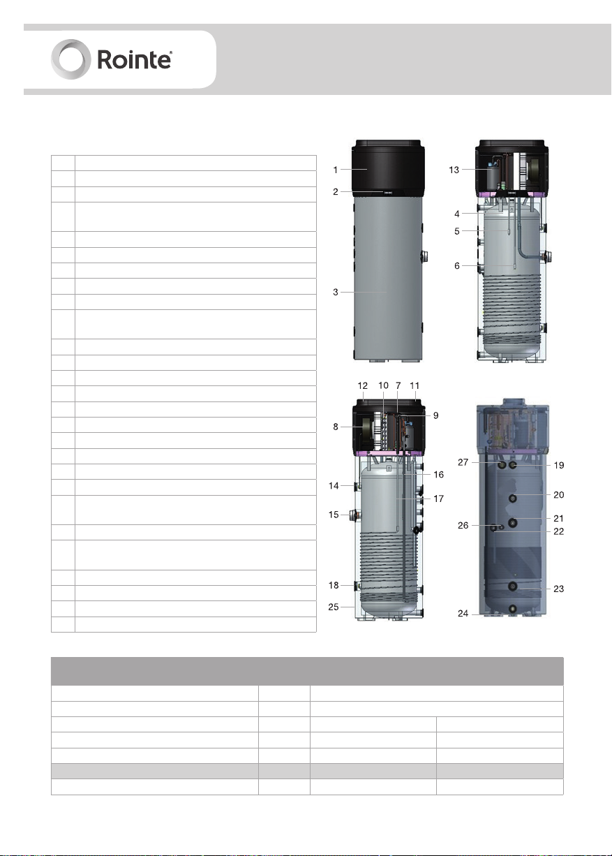
6.1. Construction characteristics
1 Heat pump 1.6 Kw
2 Control panel
3 ABS casing
Steel tank (water heater) enamelled according to EN
4
standards (capacity: 200 / 260 litres)
5 Upper probe
6 Lower probe
7 Refrigerant recharge
8 Air recirculation fan
9 Throttle valve with double capillary tube
High-efficiency finned evaporator coil. Volume of
10
liquid deposited is regulated by a thermostatic valve.
11 Air inlet (160 mm)
12 Air outlet (160 mm)
13 Hermetically-sealed rotary compressor
14 Replaceable magnesium anode
15 Electric heating element
16 Condensation pump discharge line
17 Condensation return
18 Replaceable magnesium anode
19 Hot water outlet connection joint (G 1”)
20 Recirculation mounting (G ¾”)
Input coil for solar thermal power system
21
(G 1”1/4; 1 m2 exchange surface)
22 Condensatation discharge pipe (G 1/2”)
Ouput coil for solar thermal power system
23
(G 1”1/4; 1 m2 surface)
24 Cold water inlet connection joint (G 1”)
25 50 mm polyurethane insulation
26 ½”G fitting for probe immersion sleeve
27 Pressure and temperature relief valve G1/2”
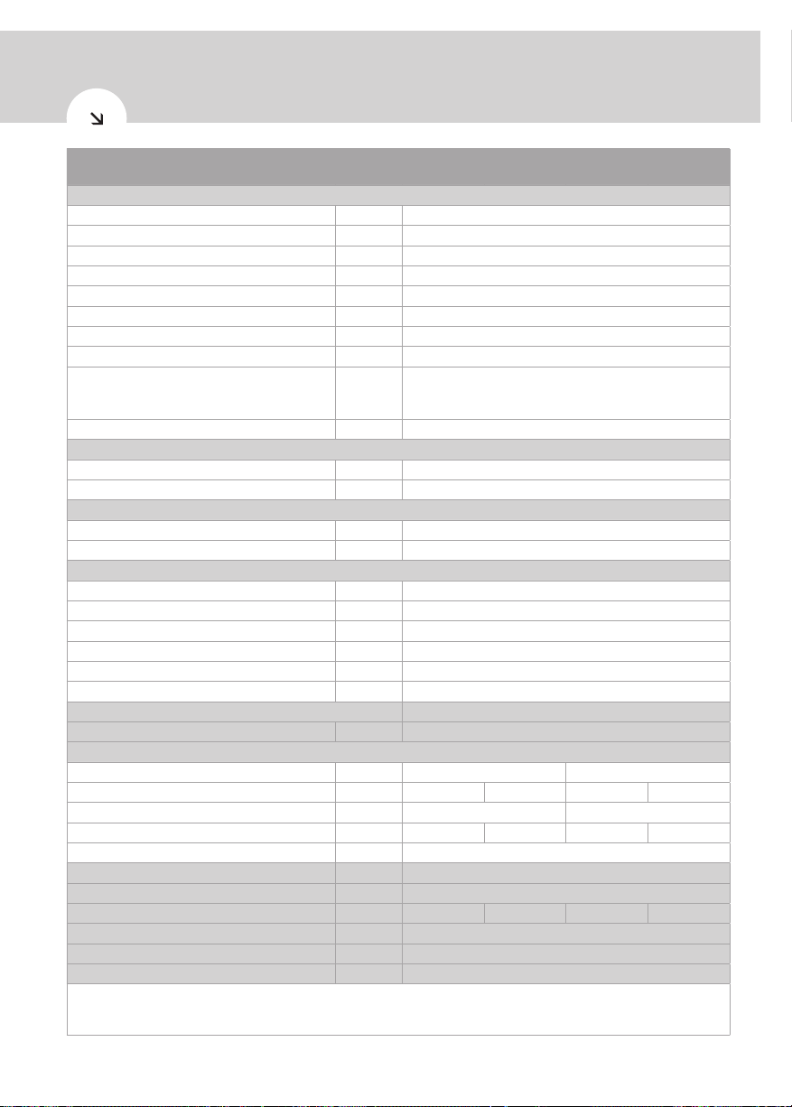
Description
Thermal power yield kW 1.6
Total thermal power kW 3.1
Heating time (1) h:m 07:16 09:44
Heating time in BOOST mode (1) h:m 03:48 04:57
Thermal losses (2) W 105 76
Dimensions (diameter x height x depth)
Ø mm 650 650
6
Unit of
measure
mm 650 x 1,714 x 600 650 x 2,004 x 600
Dalis
200DHW4
Dalis
200DHWI4
Dalis
260DHW4
Dalis
260DHWI4
DALIS
Digital electric unvented heat pump
Description
Unit of
measure
Dalis
200DHW4
Dalis
200DHWI4
Dalis
260DHW4
Dalis
260DHWI4
Electrical data
Power supply V 1/N/230
Frequency Hz 50
Degree of protection - IPX4
Max. absorption
Average power absorption kW
kW 0.50
0.37
Heating element + max. absorption kW 2
Power kW 1.5
Max. current A 2.3
16A T fuse / 16A automatic switch, characteristic C
Overload protection A
(to be expected during installation on power supply
systems
Internal protection - Single safety thermostat with manual reset
Functions
Temperature min. ÷ max. air intake 90% R.H. °C 4 ÷ 43
Min. ÷ max temperature installation site °C 4 ÷ 43
Working temperature
Max. programmable temperature - ECO °C 56
Max. programmable temperature - AUTO °C 70
Compressor (rotary) & fan (centrifugal)
Compressor protection - Thermal circuit breaker with automatic reset
Ejection outlet diameter mm 160
Revolutions per minute RPM 1,420
Nominal air capacity m3/h 350
Max. pressure head available Pa 100
Motor protection - Internal thermal circuit breaker with automatic reset
Condenser
Refrigerant R134a (load)
g 900
Wrapped externally, not in contact with water
Water storage
Capacity litres 200 260
Actual water storage capacity Vm litres 199 194 254 246
Max. volume hot water Vmax (3) litres 276 342
Connection coil solar thermal power system m2 n/a 0.9 m
2
n/a 0.9 m
Cathodic protection mm 2 x Mg anode Ø33 x 250; G1 1/4”
Insulation
Defrosting
Empty weight / when filled with water
- 50mm high density polyurethane foam
- Passive with air
Kg 81 / 280 92 / 286 93 / 347 110 / 356
Sound power indoors Lw(A) (4) dB (A) 59
Automatic anti-legionella cycle (5) - YES
Maximum working pressure
(1) temperature of incoming air supply 20°C (max.15°C), temperature of water heater storage environment 20°C, water heated from
10°C to 55°C, (according to EN 16147-2011). (2) measurements carried out according to EN 12897-2006. (3) measurements carried
out according to EN 16147-2011. (4) measurements carried out according to EN 12102-2013. (5) Automatic activation - 30 day cycle.
bar 7
2
7
7. Before installation
IMPORTANT
Failure to observe these instructions will invalidate the guarantee. Handling / instal-
lation of this product is subject to the Health & Safety At Work act. This product must
be installed by a qualified professional that is certified for Unvented Water Heater
installation. Do not attempt to install this product yourself if you are not qualified.
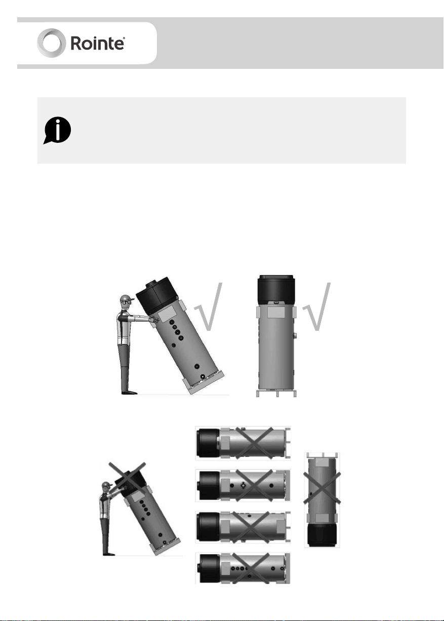
7.1. Handling and transport
• You must not put any type of pressure on the upper part of the device, as it is not structural in
nature. The product must be transported and handled in the upright position only. The screen
should be facing the upper side. If tipped, the centre of gravity will shift. Please handle with care.
• The equipment can only be transpor ted horizontally during the last kilometre, taking care to
place some supports on the underside of the product in order not to lean against upper parts.
Positions allowed for transport/handling:
Positions NOT allowed for transport / handling:
8

DALIS
Digital electric unvented heat pump
7.2 . P a cka g i ng
• If the product is not installed immediately, it should remain in its protective packaging with all
pipe/end caps in place to prevent damage or dir t deposits.
• The equipment is supplied in a cardboard box, fixed to a pallet with screws. When removing the
screws from underneath the pallet, DO NOT tilt the product.
• Use a forklift or pallet truck to unload the equipment: these should have a load capacity of at
least 250 kg. Do not drop or lower the product suddenly.
• Unpacking the product must be carried out with care so the product does not become damaged.
Ensure all the supplied fittings have been removed from the packaging.
• Keep packaging out of reach of children. Make sure that the appliance is intact and not damaged.
If in doubt, do not use or install the product and contact us.
7.3. Location
Please adhere to the following conditions when choosing a location to install the product:
• Must be installed in a damp, frost-free environment, with containment systems in case of serious
water leaks.
• Must have structural integrity that is sufficiently robust to support the product weight when the
tank is full of water, plus a flat and level surface on which to install the product.
• Must allow access to water mains supply, hot and cold water pipework and a suitable electrical
supply.
• Be readily available for connection to condensation discharge pipe.
• Be sufficiently ventilated and illuminated (if necessary) and in a space of at least 20m3.
Figure 2 - minimum installation space
9
The product MUST NOT be installed in locations where:
• The air intake contains solvents, explosive matter, grease, dirt or dust/aerosol particles.
• It is outdoors, in rooms exposed to frost, ice or damp, or in rooms where there is a lot of steam/
vapour (e.g. a bathroom).
• It is sat on floor slabs containing wooden beams e.g. attics, to avoid mechanical vibrations.
• It is prohibited to connect vented exhaust hoods to ventilation systems.
Care must be taken when installing the product in a garage or outbuilding. All exposed pipework must
be sufficiently insulated to avoid frost or ice damage.
When installing the product, ensure that all labels are visible and pipework does not restrict any work
that needs to be carried out on the various components.
Ensure the product sits flat and level on a horizontal surface as shown in figure 2.
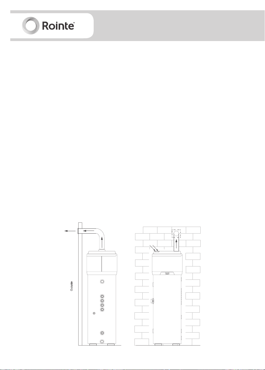
7.4. Ventilation
The product requires adequate ventilation (see figure 3). Install air ducts ensuring each one:
• Does not weigh down the product itself and allows for maintenance work.
• Is suitably protected to avoid foreign objects or materials getting inside the product.
• Does not exceed the recommended maximum length of 6 metres (with 2 x 90º elbow junctions).
• The total maximum allowable pressure drop for all components, including feed-throughs for
mounting on an external wall, in the pipe system does not exceed 100 Pa.
Figure 3 - Air duct for model with upper outlets
10
DALIS
Digital electric unvented heat pump
• During operation, the heat pump tends to lower the ambient temperature if the external air duct
is not carried out.
• An appropriate protection grid must be installed in line with the discharge pipe conveying air
to the outside, with the aim of avoiding foreign bodies from entering the equipment. In order to
guarantee maximum device performance, the grid chosen must ensure low pressure loss.
• In order to avoid the formation of condensate, insulate the air discharge pipes and the air duct
cover connections with steam-tight thermal cladding of an adequate thickness.
• If it is considered necessary in order to prevent flow noise, sound mufflers can be mounted. Fit
the pipes and connections to the heat pump with vibration damping systems.
WARNING
The simultaneous operation of an open flue firebox (e.g. an open flue fireplace) or
combustion chamber together with the product will cause a dangerous drop in am-
bient pressure. This could cause the blackflow of exhaust gas into the environment
itself.
Do not use the product with an open flue firebox or combustion chamber. Use only
sealed (approved) chamber fireboxes or combustion chambers with a separate duct
for combustion air.
Keep the doors of the room closed and hermetically sealed if they do not have a
supply of combustion air in common with inhabited areas.
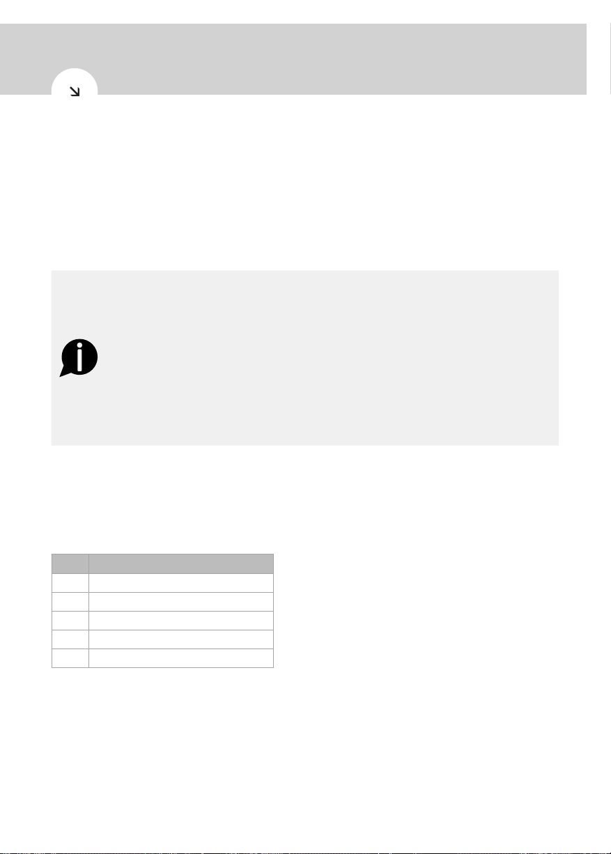
7.4.1. Ventilation accessories
Suitable ventilation accessories are available on the market, which are designed for simple and
efficient heat pump water connections. See below for ventilation accessories required for successful
and correct installation:
Item Part
1
Semi-rigid pipe - 160mm Ø lg 2m
2
90º insulated elbow - 160mm Ø
3
Collars for attaching to wall
4
Connectors for insulated pipe
5
Horizontal terminal for insulated pipe
11
8. Installation
100 mm MAX
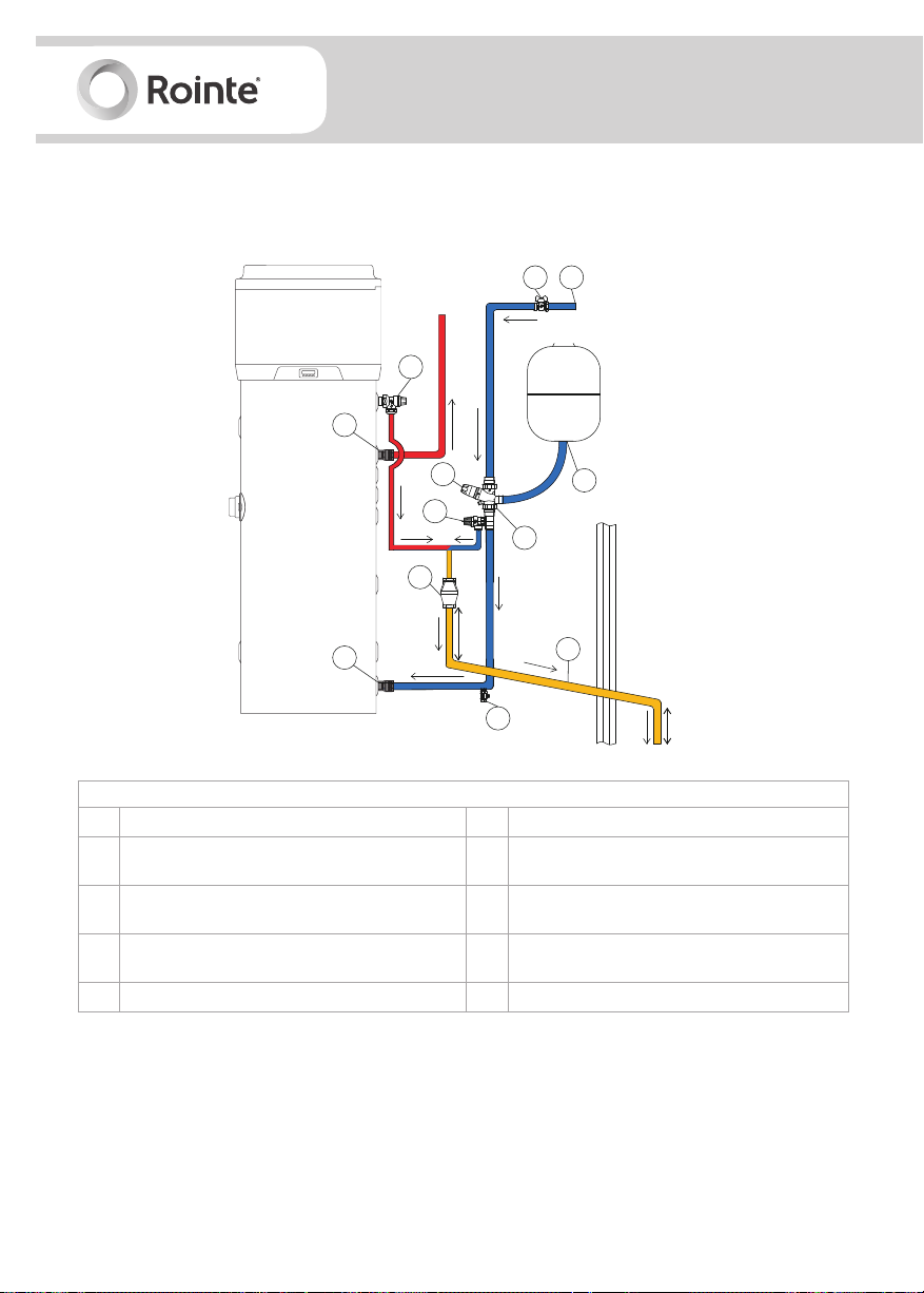
8.1. Installation diagram
Figure 5 - installation
11
Hot water outlet
2
1
Water flow
10
CW
3
5
8
to tap
9
4
11
Cold water inlet
300 mm MIN
7
6
DESCRIPTION OF INSTALLATION ITEMS
1
Mains cold water supply
2
Stop cock (not supplied)
Pressure reducing valve - (supplied in mandatory
3
installation kit, see section 4)
Check valve & expansion relief valve - (supplied
4-5
in mandatory installation kit, see section 4)
6
Discharge pipe 22 mm
7
Drain valve (not supplied)
Tundish - (supplied in mandatory installation kit,
8
see section 4)
Expansion vessel - (supplied in mandatory
9
installation kit, see section 4)
10 T/P relief valve (included)
11 Electrolytic fittings (included)
When carrying out the installation you must take care, so that:
• Extra pressure is not applied to the product e.g. by leaning on it.
• Foreign bodies and materials cannot enter inside the product.
• The selected pressure protection grid ensures low pressure loss.
• The air discharge pipes and roof connections are isolated with steam-tight thermal coating to
avoid condensation.
12
DALIS
Digital electric unvented heat pump
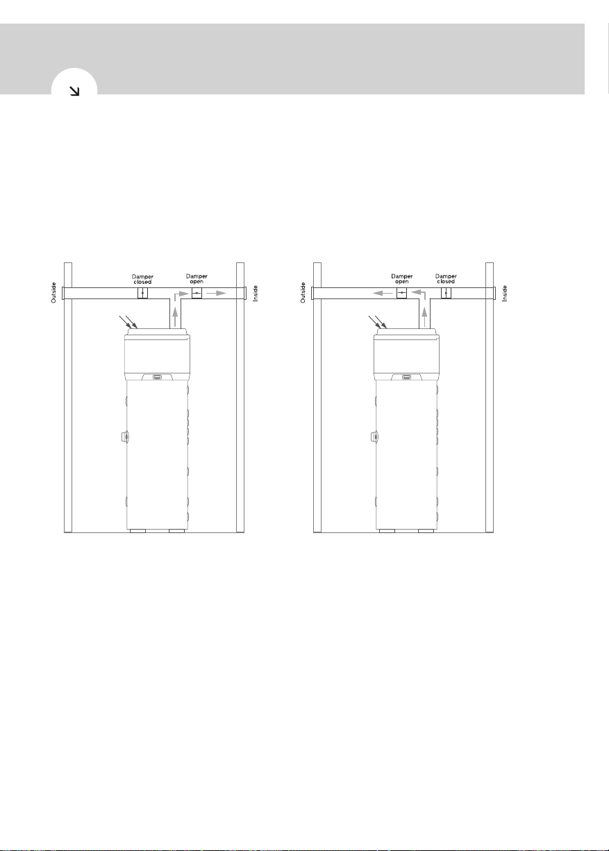
8.2. Non-standard installations
One of the unique features of heat pump heating systems is that they create a considerable drop in
air temperature usually expelled outdoors. The expelled air, in addition to being colder than the air in
the environment, is also fully dehumidified. This means that the flow of air can be fed back inside the
building again to cool rooms or spaces during warmer months, such as the summer. A dual air outlet
pipe should be installed, with 2 dampers attached, so that the expelled air flow can be directed either
indoors or outdoors - see figure 6a and 6b.
Figure 6a - installation in summer Figure 6b - installation in winter
8.3. Cold water supply
For safe per formance of the product, the tank should be directly fed by an uninterrupted supply pipe
that connects to the pressure reducing valve with a maximum supply pressure of 0.9 MPa - see figure
5. The product should not be used with a supply pressure below 0.15 MPa and a flow rate of less than
20 litres per minute. The following criteria must also be met:
• Cold water supply must come directly from the cold water mains after the mains stop valve to
the p rop e r t y.
• The inside diameter of the cold water pipework must be at least 19mm.
• Pipework should meet the water supply regulations for wholesome water.
13
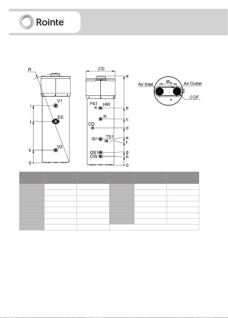
8.4. Connections
8.4.1. Overall dimensions
Figure 7 - overall dimensions
Dimensions
(+/- 5mm)
a
b
c
d
e
f
g
h
200 litres model 260 litres model
1,717 2,004
1,001 1,286
769 1,065
769 839
674 674
644 644
287 287
202 202
Dimensions
(+/- 5mm)
i
j
k
R
ØD
ØDF
M
200 litres model 260 litres model
1,000 1,286
716 931
287 287
1,751 2,025
650 650
160 160
380 380
8.4.2. Water supply connections
Connect the cold water inlet and outlet pipes to the appropriate connection points (see figure 8).
14
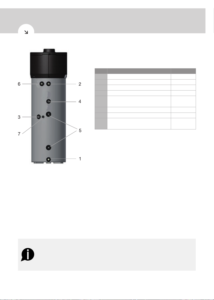
Figure 8 - overall dimensions
DALIS
Digital electric unvented heat pump
No.
1
CW: cold water inlet pipe G1”
2
HW: hot water outlet pipe G1”
3
CD: condensation drain 1/2”
4
R: recirculation pipe G 3/4”
IS1: Solar thermal power inlet coil
5
OS1: Solar thermal power outlet coil
6
P&T: T/P valve G1/2”
7
TS1: immersion sleeve probe G 1/2”
V1 / V2: protective anodes
-
EE: Heating element
Description Connection
G1”
G1 1/4”
G1 1/2”
A dirt/impurities filter must be installed in the cold water pipe inlet. The product must not operate with
a water hardness below 12ºF or hardness above 25ºF. If this is the case, then a suitably calibrated and
monitored water softener must be used.
This product is equipped with a pressure and T/P valve that complies with the BS EN 1490:2000
standard. It is factory set to operate on 7 bars pressure and a temperature of 90ºC.
The T/P safety valve for protection against over pressure and temperature must be operated regularly
to remove lime scale deposits and check it is not blocked. For more information on the T/P valve
please see section 8.9.
In case an expansion vessel is not installed, make sure that the cold water intake does not contain
any non-return valves.
WARNING
This product is capable of producing domestic hot water over 60ºC. To protect
against burns, we recommend a thermostatic mixing valve (sold separately) be in-
stalled in the hot water pipe. Also ensure there is no human burn risk at drain pipe
connecting T/P valve.
See figures 9a and 9 b for an example of a water supply connection.
15
 Loading...