

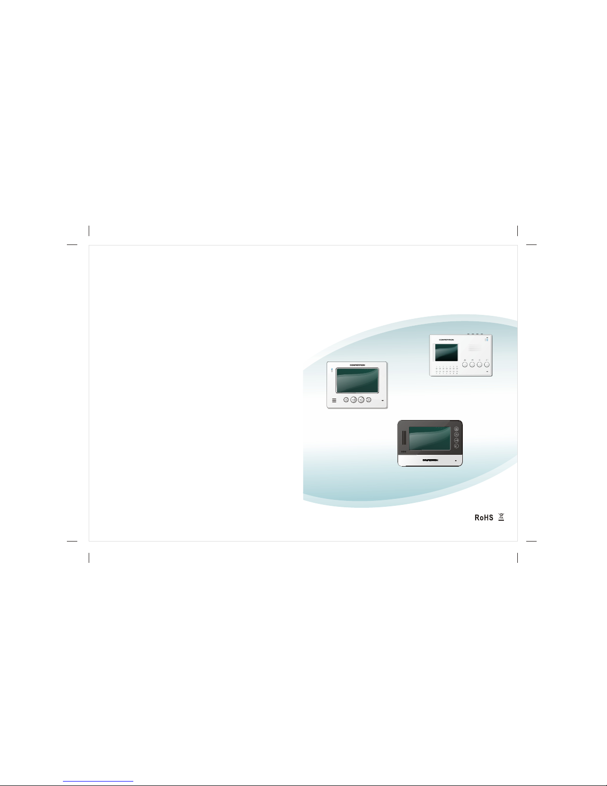
ROHS SM812CH-MV3(T), SM385CH-MV3(T), SM812CH-MV3, SM385CH-MV3, SM328CH-MV3(T) Installation And Operation Manual
...
SM812CH-MV3(T)
SM812CH-MV3
SM385CH-MV3(T)
SM385CH-MV3
SM328CH-MV3(T)
SM328CH-MV3
2013-V01
Digital Indoor Monitor
Installation and Operation Guide

CONTENTS
Plan of indoor monitor......................................................1
Technical parameters......................................................4
Basic functions................................................................5
Installation of indoor monitor...........................................6
Connection for indoor monitor.........................................7
SM385CH indoor monitor operation guide.................9-29
System startup............................................................9
Main menu interface...................................................9
System setting..........................................................10
User setting..............................................................15
Intercom....................................................................17
Call the guard station.............................................17
Call the other apartment........................................18
Intercom within the same apartment......................18
Call transfer............................................................19
Call the indoor monitor...........................................20
Monitor/unlock...........................................................21
Home security...........................................................23
Information check.....................................................26
Call lift.......................................................................29
Ring..........................................................................29
SM328/812CH indoor monitor operation guide........30-49
System startup..........................................................30
Main menu interface..................................................31
System setting..........................................................32
User setting...............................................................36
Intercom....................................................................38
Call the guard station.............................................38
Call the other apartment.........................................39
Intercom within the same apartment......................39
Call transfer............................................................40
Call the indoor monitor...........................................40
Monitor/unlock...........................................................41
Home security...........................................................43
Information check.....................................................46
Call lift.......................................................................49
Ring..........................................................................49

SM385CH-MV3/MV3(T)
Dimension: 230x152x21mm
4" screen
SM812CH-MV3/MV3(T)
Dimension: 222x170x30mm
1
7" screen
-1- -2-
SM328CH-MV3/MV3(T)
Dimension: 240x170x33mm
7" screen
-3- -4-
No.
1
2
3
4
5
11
6
7
Function
No.
Function
12
13
Power on/off
Working temperature: -20 +55
Voltage: DC 12V 10%
Conversation method:
Two-way conversation
Conversation time: 2 minutes
Memory space: 256M(built-in)
Technical parameters
Standby current: 170/185mA
Working current: 230/365mA
Standby power consumption: 2.2/2.8W
8
9
10
14
15
16
17
18
19
20
Indicator light of power
Indicator light of network
Speaker
Indicator light of message
MIC
Call management centre
Unlock door/Monitor
Talk
Volume adjustment
Mounting bracket hole
Down
Up
screen
ringtone adjustment
call lift
return key
numeric key
delete key
confirm
Colour LCD touch screen(SM385CH is button operation);
Eight section alarms with password arm/disarm;
Call, talk, unlock door, audio and video monitor;
Intercom between apartments, intercom between indoor
monitors with the same apartment, call transfer.
This system uses TCP / IP network method (through
the network to achieve functions);
Check the video message from indoor monitor;
Audio, video and control signals of the system are pure
digital signal;
Video encoding format is MPEG4; Audio encoding
format is G.711;
Information receiving function: able to receive text format
messages (eg. The notice of water and power off from
the property management center); store massage in
the indoor monitor;
The system includes an online upgrade function; system
upgrade is through the network; it makes system
maintenance more convenient.
Installation of indoor monitor
Notice: Please refer to the steps above fir the installation of
SM328/385CH.
Basic functions
-5- -6-
1.Locate the bracket on the installation place, keep it horizontal
and mark the drilling positions;
2.Drill holes according to the marked drilling positions and pad
with screw anchors;
3.Fasten the bracket with the screws properly on the installation
place;
4.Connect the indoor monitor according to the wiring diagram;
5.Mount the indoor monitor properly on the bracket hooks.
wall hole
screw anchor
(plastic)
bracket
hooks
mounting bracket hole
screw
the back
Connection for SM385CH
NO
COM
Notice: The ports in the dashed line box exist only in the indoor
monitor with (T) in the back of the model number. When the system
connects to main and slave monitors, analog outdoor station with 4+2
wire should be connected in parallel with each indoor monitor.
Connection for SM328/812CH
-7- -8-
NCNOCOM
Power
Network cable
Doorbell
Red
Black
Red
Black
Call lift
video for second
confirmed
White
White
Red
Black
Brown
Blue
second confirmed
outdoor station
Alarm
output
Black
Red
Brown
Blue
Yellow
Red
Black
Brown
Blue
Yellow
Green
Purple
White
Orange
Alarm zone 8(sos)
Alarm zone 7(Gas)
Alarm zone 6
(Fire alarm)
Alarm zone 5
Alarm zone 4
Alarm zone 3
Alarm zone 2
Alarm zone 1
GND
Doorbell
Red
Black
Network cable
Call lift
Power
Black
Red
Black
Red
Alarm
output
Brown
Blue
Yellow
White
White
Red
Black
Brown
Blue
video for second
confirmed
second confirmed
outdoor station
Red
Black
Brown
Blue
Yellow
Green
Purple
White
Orange
Alarm zone 8(sos)
Alarm zone 7(Gas)
Alarm zone 6
(Fire alarm)
Alarm zone 5
Alarm zone 4
Alarm zone 3
Alarm zone 2
Alarm zone 1
GND
Notice: The ports in the dashed line box exist only in the indoor
monitor with (T) in the back of the model number. When the system
connects to main and slave monitors, analog outdoor station with 4+2
wire should be connected in parallel with each indoor monitor.
SM385CH indoor monitor operation guide
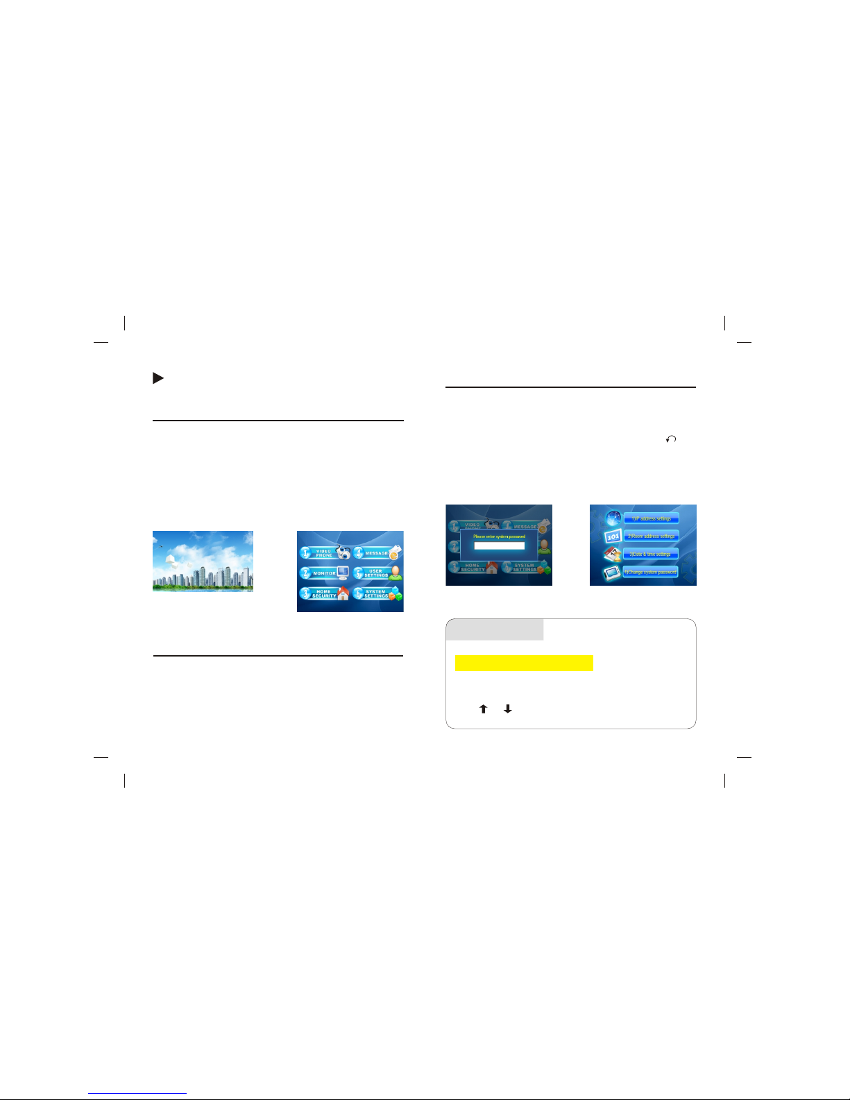
System startup
Before turn on the power, make sure the indoor monitor is
connected correctly. Then turn on the power switch on the bottom
of the indoor monitor. Picture 1-1 is the startup screen. Startup
requires 40 seconds. Main interface is as picture 1-2. The screen
server will be activated if no operation in 30 seconds. After 3
minutes screen saver mode, the machine will activate the power
saving mode.
picture 1-1
System setting
picture 1-3
picture 1-4
1. Network address setting
-9- -10-
picture 1-2
Main menu interface
After the system startup is successful, or the indoor monitor is in
the standby mode, press any button, the screen will show the main
menu as picture 1-2. There are video chat, monitor, home security,
message check, user setting, system setting.
In the main menu, press number 6 to choose the 6th option. Press
the number again to confirm the selection. Picture 1-3 the system
password interface pops up. Enter the correct system password
(factory default password is 0000. Press * to delete. Press to
return) and press # to enter to picture 1-4 system setting interface.
There are network address setting, room number setting, time
setting, system password modification.
Operation
In picture 1-4, press number 1 to choose the first option. Press
number 1 again to confirm the selection. Picture 1-5 will show.
Press or to move from upper to lower frame and fill
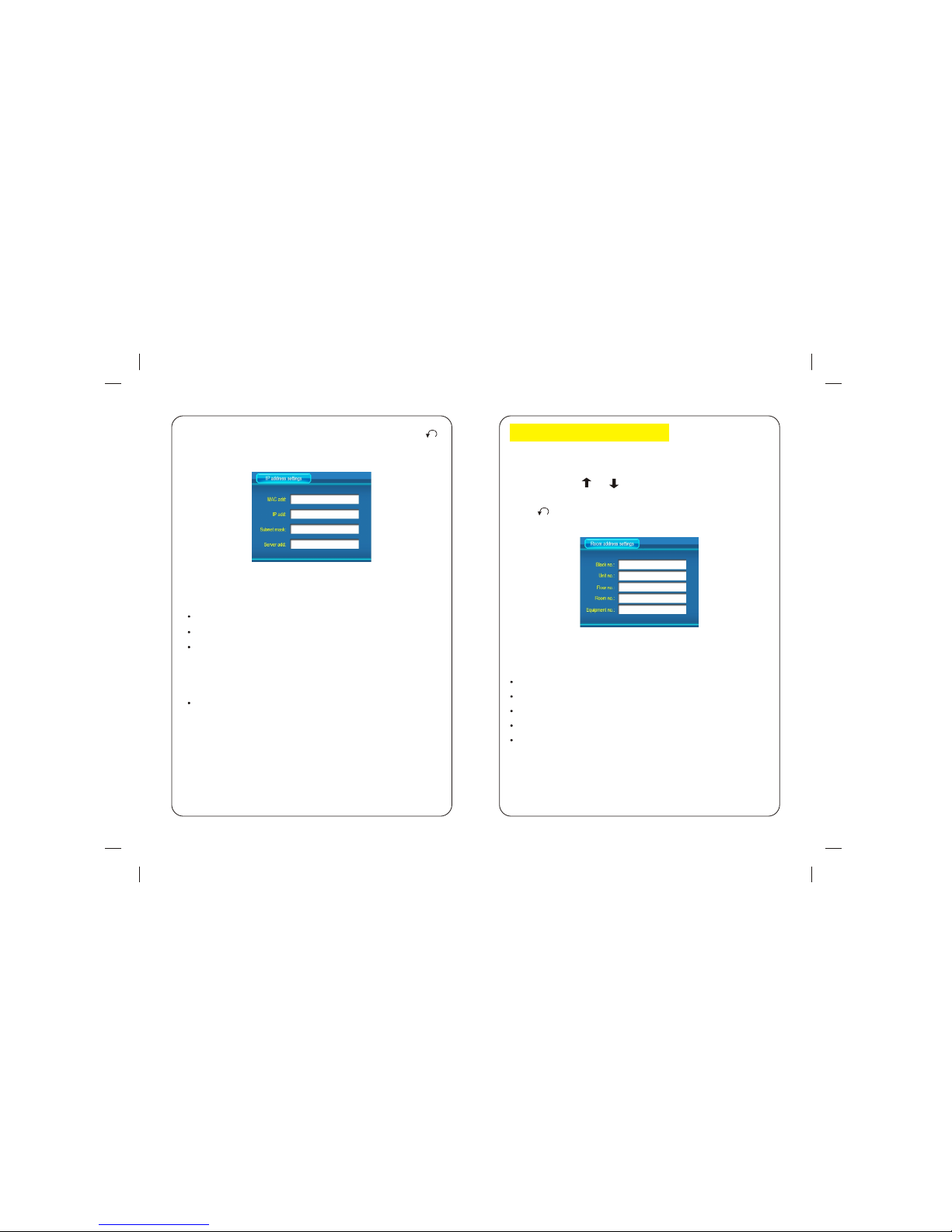
picture 1-5
2.Equipment address setting
picture 1-6
-11-
-12-
In picture 1-4, press number 2 to choose the second option.
Press number 2 again to confirm the selection. Picture 1-6
will show. Press or to move from upper to lower frame
and fill in the blanks. Press * to delete. Press # to confirm.
Press to return.
Building number: 0001(4-digit)
Unit number: 01 (2-digit)
Floor number:01 (2-digit)
Room number: 01 (2-digit)
Equipment number: 0 (0 indicates main machine, 1-9
indicate the number of slave machines)
in the blanks. Press * to delete. Press # to confirm. Press
to return.
MAC address: 01:01:00 (Address must be unique)
IP address:192.168.010.100(Address must be unique)
Subnet Mask: 255.255.000.000 (If require cross network
communication, set the subnet mask as 255.255.000.000.
For example, IP address 192.168.000.010 communicates
with IP address 192.168.022.010)
Server address: 192.168.000.006 (Set the server address
according to the guard station IP address)
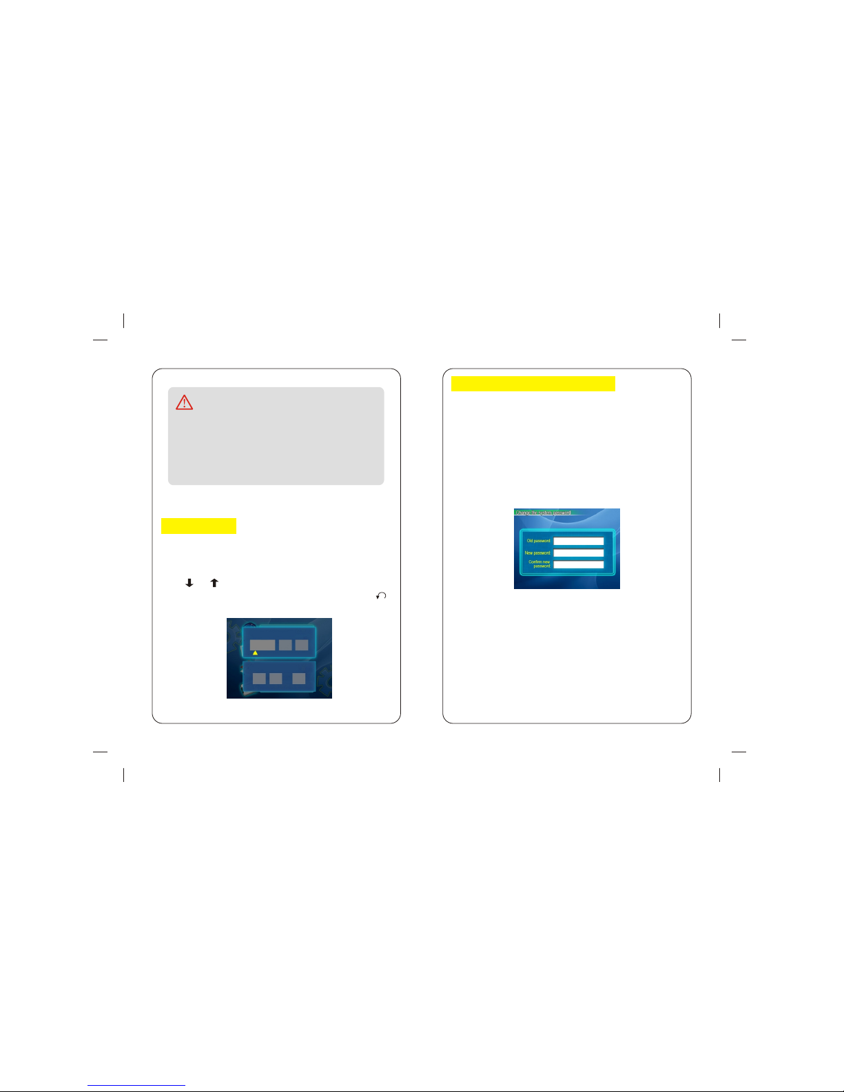
In picture 1-4, press number 4 to choose the second option.
Press number 4 again to confirm the selection. Picture 1-8
will show.
Enter the correct 4-digit password, then the cursor will move
to the lower blank NEW PASSWORD. Enter the new 4-digit
password and confirm it again. Press # to confirm and get
confirm information: Password is changed successfully.
Notice
3.Time setting
picture 1-7
4.System password modification
picture 1-8
-13-
-14-
In the same network, the MAC address and IP address
can not be the same in any equipment (including
outdoor station, indoor monitor and slave indoor
monitors). Please according to the actual situation to
set the equipments.
In picture 1-4, press number 3 to choose the second option.
Press number 3 again to confirm the selection. Picture 1-7
will show.
Press or to move from upper to lower frame and fill
in the blanks. Press * to delete. Press # to confirm. Press
to return.
Date Setting 2013/10/10
Time Setting 08:10:30
2013 10 10
08 10 30
 Loading...