


I
QSM-622E
User’s Manual
Version 1.0
2017.05
85
Wide Range Temperature
Qseven CPU Module
85

- II -
This page is intentionally left blank.

- i -
Revision History
Version Release Time Description
1.0 May, 2017 Initial release

- ii -
Contents
Revision History .................................................................................i
Contents ............................................................................................. ii
Preface...............................................................................................iv
Copyright Notice .................................................................................... iv
Declaration of Conformity ...................................................................... iv
CE ................................................................................................... iv
FCC Class A .................................................................................... v
RoHS ............................................................................................... v
SVHC / REACH .............................................................................. vi
Warning .................................................................................................. vi
Replacing the Lithium Battery ................................................................ vi
Technical Support .................................................................................. vi
Warranty.................................................................................................vii
Chapter 1 - Introduction .................................................................... 1
1.1. The Product ..................................................................................... 2
1.2. About this Manual ............................................................................ 2
1.3. Specications ................................................................................... 3
1.4. Inside the Package ..........................................................................4
1.5. Ordering Information ........................................................................ 4
1.6 Optional Accessories ........................................................................4
1.7. Driver Installation Note .....................................................................5
Chapter 2 - Board Overview .............................................................7
2.1. Board Dimensions ............................................................................8
2.2. Block Diagram ..................................................................................9
2.3. Connector Pin Denition ................................................................10
Chapter 3 - BIOS .............................................................................. 13
3.1 Main ...............................................................................................14
3.2 Advanced .......................................................................................16
3.2.1 F81866 Super IO Conguration ...........................................17
3.2.2 Hardware Monitor ................................................................19
3.2.3 CPU Conguration ............................................................... 20
3.2.4 IDE Conguration ................................................................21
3.2.5 LPSS & SCC Conguration ................................................22
3.2.6 CSM Conguration ...............................................................24
3.2.7 USB Conguration ............................................................... 26
3.3 Chipset ........................................................................................... 28
3.3.1 North Bridge ..........................................................................29
3.3.2 South Bridge ......................................................................... 32
3.4 Security .......................................................................................... 35
Contents

- iii -
Contents
3.5 Boot ................................................................................................36
3.6 Save & Exit ....................................................................................37

- iv -
Preface
Copyright Notice
All Rights Reserved.
The information in this document is subject to change without prior notice in
order to improve the reliability, design and function. It does not represent a
commitment on the part of the manufacturer.
Under no circumstances will the manufacturer be liable for any direct, indirect,
special, incidental, or consequential damages arising from the use or inability
to use the product or documentation, even if advised of the possibility of such
damages.
This document contains proprietary information protected by copyright. All rights
are reserved. No part of this manual may be reproduced by any mechanical,
electronic, or other means in any form without prior written permission of the
manufacturer.
Declaration of Conformity
CE
The CE symbol on your product indicates that it is in compliance with the
directives of the Union European (EU). A Certicate of Compliance is available
by contacting Technical Support.
This product has passed the CE test for environmental specications when
shielded cables are used for external wiring. We recommend the use of shielded
cables. This kind of cable is available from ARBOR. Please contact your local
supplier for ordering information.
This product has passed the CE test for environmental specications. Test
conditions for passing included the equipment being operated within an
industrial enclosure. In order to protect the product from being damaged by ESD
(Electrostatic Discharge) and EMI leakage, we strongly recommend the use of
CE-compliant industrial enclosure products.
Warning
This is a class A product. In a domestic environment this product may cause
radio interference in which case the user may be required to take adequate
measures.
Preface

- v -
Preface
FCC Class A
This device complies with Part 15 of the FCC Rules. Operation is subject to the
following two conditions:
(1)This device may not cause harmful interference, and
(2)This device must accept any interference received, including interference that
may cause undesired operation.
NOTE:
This equipment has been tested and found to comply with the limits for a
Class A digital device, pursuant to Part 15 of the FCC Rules. These limits are
designed to provide reasonable protection against harmful interference when the
equipment is operated in a commercial environment. This equipment generates,
uses, and can radiate radio frequency energy and, if not installed and used in
accordance with the instruction manual, may cause harmful interference to radio
communications. Operation of this equipment in a residential area is likely to
cause harmful interference in which case the user will be required to correct the
interference at his own expense.
RoHS
ARBOR Technology Corp. certies that all components in its products are in
compliance and conform to the European Union’s Restriction of Use of Hazardous Substances in Electrical and Electronic Equipment (RoHS) Directive
2002/95/EC.
The above mentioned directive was published on 2/13/2003. The main purpose of the directive is to prohibit the use of lead, mercury, cadmium, hexavalent chromium, polybrominated biphenyls (PBB), and polybrominated diphenyl
ethers (PBDE) in electrical and electronic products. Member states of the EU
are to enforce by 7/1/2006.
ARBOR Technology Corp. hereby states that the listed products do not contain
unintentional additions of lead, mercury, hex chrome, PBB or PBDB that exceed a maximum concentration value of 0.1% by weight or for cadmium exceed
0.01% by weight, per homogenous material. Homogenous material is dened
as a substance or mixture of substances with uniform composition (such as solders, resins, plating, etc.). Lead-free solder is used for all terminations (Sn(96-
96.5%), Ag(3.0-3.5%) and Cu(0.5%)).

- vi -
Preface
SVHC / REACH
To minimize the environmental impact and take more responsibility to the earth
we live, Arbor hereby conrms all products comply with the restriction of SVHC
(Substances of Very High Concern) in (EC) 1907/2006 (REACH --Registration,
Evaluation, Authorization, and Restriction of Chemicals) regulated by the
European Union.
All substances listed in SVHC < 0.1 % by weight (1000 ppm)
Warning
Single Board Computers and their components contain very delicate
Integrated Circuits (IC). To protect the Single Board Computer and its
components against damage from static electricity, you should always follow the
following precautions when handling it:
1. Disconnect your Single Board Computer from the power source when you
want to work on the inside.
2. Hold the board by the edges and try not to touch the IC chips, leads or
circuitry.
3. Use a grounded wrist strap when handling computer components.
4. Place components on a grounded antistatic pad or on the bag that comes
with the Single Board Computer, whenever components are separated from
the system.
Replacing the Lithium Battery
Incorrect replacement of the lithium battery may lead to a risk of explosion.
The lithium battery must be replaced with an identical battery or a battery type
recommended by the manufacturer.
Do not throw lithium batteries into the trash-can. It must be disposed of in
accordance with local regulations concerning special waste.
Technical Support
If you have any technical difculties, please do not hesitate to call or e-mail our
customer service.
http://www.arbor-technology.com
E-mail:info@arbor.com.tw

- vii -
Preface
Warranty
This product is warranted to be in good working order for a period of two years
from the date of purchase. Should this product fail to be in good working order
at any time during this period, we will, at our option, replace or repair it at no
additional charge except as set forth in the following terms. This warranty does
not apply to products damaged by misuse, modications, accident or disaster.
Vendor assumes no liability for any damages, lost prots, lost savings or any other
incidental or consequential damage resulting from the use, misuse of, or inability to
use this product. Vendor will not be liable for any claim made by any other related party.
Vendors disclaim all other warranties, either expressed or implied, including but
not limited to implied warranties of merchantability and tness for a particular
purpose, with respect to the hardware, the accompanying product’s manual(s)
and written materials, and any accompanying hardware. This limited warranty
gives you specic legal rights.
Return authorization must be obtained from the vendor before returned
merchandise will be accepted. Authorization can be obtained by calling or faxing
the vendor and requesting a Return Merchandise Authorization (RMA) number.
Returned goods should always be accompanied by a clear problem description.

- viii -
This page is intentionally left blank.

- 1 -
1Chapter 1
Introduction
Chapter 1 - Introduction

- 2 -
Introduction
1.1. The Product
• Fanless Design
• Soldered Onboard Intel® Atom™ Processor E3800 family
• Intel® i210IT PCIe GbE controller
• Dual Channels 24-bit LVDS, DDI Port
• Wide-temeprature Operating Temp.: -40 ~ 85°C
1.2. About this Manual
This manual is intended for experienced users and integrators with hardware
knowledge of computers. If you are not sure about the description in this manual,
consult your vendor before further handling.
We recommend that you keep one copy of this manual for the quick reference
for any necessary maintenance in the future. Thank you for choosing ARBOR
products.

- 3 -
Introduction
1.3. Specications
Form Factor
Qseven® CPU Module
CPU
Soldered onboard Intel® Atom™ Processor E3825
dual-core 1.33GHz or E3845 quadcore 1.91GHz
System Memory Soldered onboard 2GB / 4GB DDR3L SDRAM
VGA/ LCD Controller
SoC Integrated Intel® Gen7 graphic
Ethernet controller
1 x Intel® i210IT PCIe GbE controller
Audio HD Audio Link
BIOS Insyde UEFI BIOS
Serial ATA 2 x Serial ATA ports w/ 300MB/s HDD transfer rate
Universal Serial Bus 8 x USB 2.0 ports(Port0~3 support USB2.0 only)*
Storage Soldered onboard 16GB eMMC (Optional)**
Graphics Interface
LCD: Dual Channels 24-bit LVDS, resolution up to
1920x1200
Analog RGB signals (via Qseven® GF reserved pin)
1 x DDI port
Expansion Bus 3 x PCIe x1 lanes, I2C
Operating Temp. -40ºC ~ 85ºC (-40ºF ~ 185ºF)
Humidity 10 ~ 95%@ 85ºC (non-condensing)
Watchdog Timer 1~ 255 levels reset
Dimension (L x W) 70 x 70 mm (2.76” x 2.76”)
*Please don’t hot plug USB device with USB port0 to avoid that OS can’t
recognize the device (refer to Pin-94&96 in “2.3. Connector Pin Denition” on
page12) .
And USB port 0~3 support USB2.0 only (refer to “2.3. Connector Pin Denition”
on page12).
**Windows 7 does not include any driver support for eMMC devices. If you select
Windows 7 as your OS selection in BIOS, the eMMC device is disabled and
grayed out.
- 4 -
Introduction
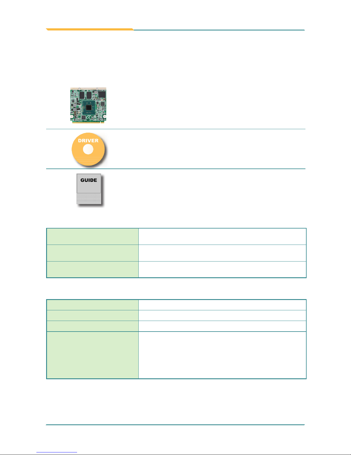
1.4. Inside the Package
Before starting with the installation, make sure the following items are shipped.
If any of the items is missing or appears damaged, contact your local dealer or
distributor.
1 x QSM-662E Qseven® CPU Module
1 x Driver CD
1 x Quick Installation Guide
1.5. Ordering Information
QSM-662E-E3825-2G
Intel® Atom™ Processor Bay Trail-I E3825 Qseven® WT CPU
module w / 2GB memory soldered on module
QSM-662E-E3845-2G
Intel® Atom™ Processor Bay Trail-I E3845 Qseven® WT CPU module w / 2GB memory soldered on module
QSM-662E-E3845-4G
Intel® Atom™ Processor Bay Trail-I E3845 Qseven® WT CPU module w / 4GB memory soldered on module
1.6 Optional Accessories
HS-0662-F1 Heat spreader
HS-0000-W3
Universal evaluation Heatsink for Qseven® CPU module
PBQ-3000
Qseven® EPIC evaluation board
CBK-06-3000-00
Cable kit
1 x USB cable
1 x USB2 cable
2 x Serial port cables
1 x SATA cable
1 x SATA power cable

- 5 -
Introduction
1.7. Driver Installation Note
The CPU board supports Windows 7 and Windows 8.1. Find the necessary
drivers on the CD that comes with your purchase. For different OS, the driver/
utility installation may vary slightly, but generally they are similar.
Find the drivers on CD by the following paths:
Windows 8.1
Driver Path
Audio
\Audio\32 bit
\Audio\64 bit
Chipset
\Chipset\32bit\Chipset Kit 57833 _32
\Chipset\64bit\Chipset Kit 57833 _64
Ethernet
\Ethernet\Intel\32bit\LAN 18.8.1 _32
\Ethernet\Intel\64bit\LAN 18.8.1 _64
GPIO/I2C
\GPIO I2C\windows 8 32_64\Intel_Processor_Win8_IO_Drivers_
Gold_MR1
Graphics
\Graphic\win32_153339
\Graphic\win64_153339
MBI \MBI\MBI Kit 58443 20140106_windows 8_8.132_64
TXE \TXE\TXE Kit 100885

- 6 -
Introduction
Windows 7
Driver Path
Audio
\Audio\32 bit
\Audio\64 bit
Chipset
\Chipset\32bit\Chipset Kit 57833 _32
\Chipset\64bit\Chipset Kit 57833 _64
Ethernet
\Ethernet\Intel\32bit\LAN 18.8.1 _32
\Ethernet\Intel\64bit\LAN 18.8.1 _64
Graphics
\Graphic\win32_153339
\Graphic\win64_153339
GPIO/I2C
\GPIO I2C\windows 7 32_64\Intel_Atom_E3800_Processor_Win7_
IO_Drivers_MR1_v4_0
TXE \TXE\TXE Kit 100885
USB3.0 \USB3.0\SetupUSB3
WINUSB \USB

- 7 -
2Chapter 2
Board
Overview
Chapter 2 - Board Overview

- 8 -
Board Overview
2.1. Board Dimensions
22.86
36.58
35.94
15.77
39.27
1.20
18.00
52.00
70.00
3.00
67.00
2.50
70.00
56.50
Unit:mm

- 9 -
Board Overview
2.2. Block Diagram
I2C
Q7 Golden Finger
Dual Channels 24-bit LVDS
NXP
PTN3460
3 x PCIex1
4 x USB 2.0 Ports(
Support USB1.1/2.0)
1 x HSIC
SMSC
USB4604
LPC I/F
4 x USB 2.0 host ports(Support USB2.0 only)
HD Audio Link
SATA0
SATA1
1 x PCIe x 1
GbE
GbE Controller
Intel i210IT
Analog R.G.B. (to Q7 RSV pin)
DDR3L-1066/1333 MT/s Onboard DDR3L
2GB SDRAM
1 x DDI port (DDI1)
1 x eDP port
Intel®
Atom
Processor
E3800
family
eMMC 4.5
Onboard eMMC
up to 16GB

- 10 -
Board Overview
2.3. Connector Pin Denition
Pin Signal Pin Signal
1 GND 2 GND
3 GBE_MDI3- 4 GBE_MDI2-
5 GBE_MDI3+ 6 GBE_MDI2+
7 GBE_LINK100# 8 GBE_LINK1000#
9 GBE_MDI1- 10 GBE_MDI0-
11 GBE_MDI1+ 12 GBE_MDI0+
13 GBE_LINK# 14 GBE_ACT#
15 GBE_CTREF 16 SUS_S5#
17 WAKE# 18 SUS_S3#
19 SUS_STAT# 20 PWRBTN#
21 SLP_BTN# 22 LID_BTN#
23 GND 24 GND
KEY KEY
25 GND 26 PWGIN
27 BATLOW# 28 RSTBTN#
29 SATA0_TX+ 30 SATA1_TX+
31 SATA0_TX- 32 SATA1_TX-
33 SATA_ACT# 34 GND
35 SATA0_RX+ 36 SATA1_RX+
37 SATA0_RX- 38 SATA1_RX-
39 GND 40 GND
41 BIOS_DISABLE# 42 SDIO_CLK# (N/C)
43 SDIO_CD# (N/C) 44 SDIO_LED (N/C)
45 SDIO_CMD (N/C) 46 SDIO_WP (N/C)
47 SDIO_PWR# (N/C) 48 SDIO_DAT1 (N/C)
49 SDIO_DAT0 (N/C) 50 SDIO_DAT3 (N/C)
51 SDIO_DAT2 (N/C) 52 SDIO_DAT5 (N/C)
53 SDIO_DAT4 (N/C) 54 SDIO_DAT7 (N/C)
55 SDIO_DAT6 (N/C) 56 RSVD (N/C)
57 GND 58 GND
59 HDA_SYNC 60 SMB_CLK
61 HDA_RST# 62 SMB_DAT
63 HDA_BITCLK 64
SMB_ALERT#
Pin Signal Pin Signal
65 HDA_SDI 66 I2C_CLK
67 HDA_SDO 68 I2C_DAT
69 THRM# 70 WDTRIG#
71 THRMTRIP# 72 WDOUT (N/C)
73 GND 74 GND
75 USB_P7- 76 USB_P6-
77 USB_P7+ 78 USB_P6+
79 USB_6_7_OC# 80 USB_4_5_OC#
81 USB_P5- 82 USB_P4-
83 USB_P5+ 84 USB_P4+
85 USB_2_3_OC# 86 USB_0_1_OC#
87 USB_P3- 88 USB_P2-
89 USB_P3+ 90 USB_P2+
91 USB_HOST_PRES# (N/C) 92
USB_HC_SEL (N/C)
93 USB_P1- 94 USB_P0-
95 USB_P1+ 96 USB_P0+
97 GND 98 GND
99 LVDS_A0+ 100 LVDS_B0+
101 LVDS_A0- 102 LVDS_B0-
103 LVDS_A1+ 104 LVDS_B1+
105 LVDS_A1- 106 LVDS_B1-
107 LVDS_A2+ 108 LVDS_B2+
109 LVDS_A2- 110 LVDS_B2-
111 LVDS_PPEN 112 LVDS_BLEN
113 LVDS_A3+ 11 4 LVDS_B3+
115 LVDS_A3- 116 LVDS_B3-
117 GND 118 GND
119 LVDS_A_CLK+ 120
LVDS_B_CLK+
121 LVDS_A_CLK- 122
LVDS_B_CLK-
123 LVDS_BLT_CTRL 124 RSVD (N/C)
125 LVDS_DID_DAT 126
CRT_DDC_Data
127 LVDS_DID_CLK 128
CRT_DDC_CLK
129 CAN0_TX (N/C) 130 CAN0_RX (N/C)

- 11 -
Board Overview
Pin Signal Pin Signal
131 DP1_TX3_P 132 SDVO_INT+ (N/C)
133 DP1_TX3_N 134 SDVO_INT- (N/C)
135 GND 136 GND
137 DP1_TX1_P 138 DP1_AUX_C_P
139 DP1_TX1_N 140 DP1_AUX_C_N
141 GND 142 GND
143 DP1_TX2_P 144
SDVO_TVCLKIN+ (N/C)
145 DP1_TX2_N 146
SDVO_TVCLKIN- (N/C)
147 GND 148 GND
149 DP1_TX0_P 150 DP1_AUX_N
151 DP1_TX0_N 152 DP1_AUX_P
153 HDMI_HPD# 154 DP_HPD#
155 PCIE_CLK_REF+ 156 PCIE_WAKE#
157 PCIE_CLK_REF- 158 PCIE_RST#
159 GND 160 GND
161 PCIE3_TX+ (N/C) 162 PCIE3_RX+ (N/C)
163 PCIE3_TX- (N/C) 164 PCIE3_RX- (N/C)
165 GND 166 GND
167 PCIE2_TX+ 168 PCIE2_RX+
169 PCIE2_TX- 170 PCIE2_RX-
171 EXCD0_PERST# 172 EXCD1_PERST#
173 PCIE1_TX+ 174 PCIE1_RX+
175 PCIE1_TX- 176 PCIE1_RX-
177
EXCD0_CPPE#
178
EXCD1_CPPE#
179 PCIE0_TX+ 180 PCIE0_RX+
181 PCIE0_TX- 182 PCIE0_RX-
183 GND 184 GND
185 LPC_AD0 186 LPC_AD1
187 LPC_AD2 188 LPC_AD3
189 LPC_CLK 190 LPC_FRAME#
191 SERIRQ 192 LPC_LDRQ# (N/C)
193 VCC_RTC 194 SPKR
195
FAN_TACHOIN (N/C)
196
FAN_PWMOUT (N/C)
Pin Signal Pin Signal
197 GND 198 GND
199 SPI_MOSI 200 SPI_CS0#
201 SPI_MISO 202 SPI_CS1# (N/C)
203 SPI_SCLK 204 CRT_RED
205 VCC_5V_SB 206 VCC_5V_SB
207 CRT_VSYNC 208 CRT_GREEN
209 CRT_HSYNC 210 CRT_BLUE
211 +5V 212 +5V
213 +5V 214 +5V
215 +5V 216 +5V
217 +5V 218 +5V
219 +5V 220 +5V
221 +5V 222 +5V
223 +5V 224 +5V
225 +5V 226 +5V
227 +5V 228 +5V
229 +5V 230 +5V

- 12 -
This page is intentionally left blank.

- 13 -
Chapter 3 - BIOS
3Chapter 3
BIOS

- 14 -
BIOS
3.1 Main
The AMI BIOS provides a Setup utility program for specifying the system
congurations and settings. The BIOS RAM of the system stores the Setup
utility and congurations. When you turn on the computer, the AMI BIOS is
immediately activated. To enter the BIOS SETUP UTILITY, press “Delete”
once the power is turned on.
The Main Setup screen lists the following information:
Aptio Setup Utility - Copyright (C) 2016 American Megatrends, Inc.
Version 2.17.1255. Copyright (C) 2016 American Megatrendes, Inc.
Advanced Chipset BootSecurity Save & Exit
BIOS Name EmQ-i2301
BIOS Version 9.01
Build Date and Time 11/25/2016 19:07:03
CPU Configuration
Microcode Patch 907
BayTrail SoC D0 Setpping
Memory Information
Total Memory 4098 MB (DDR3L)
TXE Information
Sec RC Version 00.05.00.00
TXE FW Version 01.00.52.1129
System Language [English]
System Date [Fri 01/06/2017]
System Time [01:39:30]
Set the Date. Use Tab
to Switch between Date
elements.
→←: Select Screen
↓↑: Select Item
Enter: Select
+/-: Change Opt.
F1: General Help
F2: Previous Values
F9: Optimized Defaults
F10: Save and Exit
ESC: Exit
Main
Setting Description
System Language Choose the system default language.
System Date
Set the system date. Use Tab to switch between Data
elements. Note that the ‘Day’ automatically changes
when you set the date.
► The date format is: Day: Sun to Sat
Month: 1 to 12
Date: 1 to 31
Year: 1998 to 2099

- 15 -
BIOS
Keystroke Function
◄ ►
Move to highlight a particular conguration screen from
the top menu bar / Move to highlight items on the screen
▼ ▲ Move to highlight previous/next item
Enter Select and access a setup item/eld
Esc
On the Main Menu – Quit the setup and not save
changes into CMOS (a message screen will display
and ask you to select “OK” or “Cancel” for exiting and
discarding changes. Use “←” and “→” to select and
press “Enter” to conrm)
On the Sub Menu – Exit current page and return to main
menu
Page Up / +
Increase the numeric value on a selected setup item /
make change
Page Down / -
Decrease the numeric value on a selected setup item /
make change
F1 Activate “General Help” screen
F10
Save the changes that have been made in the setup and
exit. (a message screen will display and ask you to select
“OK” or “Cancel” for exiting and saving changes. Use “←”
and “→” to select and press “Enter” to conrm)
Key Commands
BIOS Setup Utility is mainly a key-based navigation interface. Please refer to
the following key command instructions for navigation process.
System Time
Set the system time. Use Tab to switch between
Time elements.
► The time format is: Hour: 00 to 23
Minute: 00 to 59
Second: 00 to 59

- 16 -
BIOS
3.2 Advanced
Aptio Setup Utility - Copyright (C) 2016 American Megatrends, Inc.
Version 2.17.1255. Copyright (C) 2016 American Megatrendes, Inc.
► F81866 Super IO Configuration
► HardWare Monitor
► CPU Configuration
► IDE Configuration
► LPSS & SCC Configuration
► CSM Configuration
► USB Configuration
System Super IO Chip
Parameters.
→←: Select Screen
↓↑: Select Item
Enter: Select
+/-: Change Opt.
F1: General Help
F2: Previous Values
F9: Optimized Defaults
F10: Save and Exit
ESC: Exit
Advanced
Chipset Security Save & ExitMain
Boot
Setting Description
F81866 Super IO
Conguration
See section 3.2.1 F81866 Super IO Configuration
Hardware Monitor See section 3.2.2 Hardware Monitor
CPU Conguration See section 3.2.3 CPU Configuration
IDE Conguration See section 3.2.4 IDE Configuration
LPSS & SCC Conguration See section 3.2.5 LPSS & SCC Configuration
CSM Conguration See section 3.2.6 CSM Configuration
USB Conguration See section 3.2.7 USB Configuration

- 17 -
BIOS
3.2.1 F81866 Super IO Conguration
Aptio Setup Utility - Copyright (C) 2012 American Megatrends, Inc.
Version 2.15.1226. Copyright (C) 2012 American Megatrendes, Inc.
F81866 Super IO Configuration
Super IO Chip F81866
► Serial Port 1 Configuration
► Serial Port 2 Configuration
► Serial Port 3 Configuration
► Serial Port 4 Configuration
► Serial Port 5 Configuration
► Serial Port 6 Configuration
Set Parameters of
Serial Port 1 (CONA)
→←: Select Screen
↓↑: Select Item
Enter: Select
+/-: Change Opt.
F1: General Help
F2: Previous Values
F9: Optimized Defaults
F10: Save and Exit
ESC: Exit
Advanced
Aptio Setup Utility - Copyright (C) 2016 American Megatrends, Inc.
Version 2.17.1255. Copyright (C) 2016 American Megatrendes, Inc.
Setting Description
Serial Port Enable (default) or Disable Serial Port (COM).
Select an optimal setting for Super IO device.
► Options for Serial Port 1 (COMA):
Auto (default);
IO=3F8h; IRQ=4;
IO=3F8h; IRQ=3, 4, 5, 6, 7, 9, 10, 11, 12;
IO=2F8h; IRQ=3, 4, 5, 6, 7, 9, 10, 11, 12;
IO=3E8h; IRQ=3, 4, 5, 6, 7, 9, 10, 11, 12;
IO=2E8h; IRQ=3, 4, 5, 6, 7, 9, 10, 11, 12;
► Options for Serial Port 2 (COMB):
Auto (default);
IO=2F8h; IRQ=3;
IO=3F8h; IRQ=3, 4, 5, 6, 7, 9, 10, 11, 12;
IO=2F8h; IRQ=3, 4, 5, 6, 7, 9, 10, 11, 12;
IO=3E8h; IRQ=3, 4, 5, 6, 7, 9, 10, 11, 12;
IO=2E8h; IRQ=3, 4, 5, 6, 7, 9, 10, 11, 12;

- 18 -
BIOS
Change Settings
► Options for Serial Port 3 (COMC):
Auto (default);
IO=3E8h; IRQ=7
IO=3E8h; IRQ=3, 4, 5, 6, 7, 9, 10, 11, 12;
IO=2E8h; IRQ=3, 4, 5, 6, 7, 9, 10, 11, 12;
IO=2F0h; IRQ=3, 4, 5, 6, 7, 9, 10, 11, 12;
IO=2E0h; IRQ=3, 4, 5, 6, 7, 9, 10, 11, 12;
► Options for Serial Port 4 (COMD):
Auto (default);
IO=2E8h; IRQ=10;
IO=3E8h; IRQ=3, 4, 5, 6, 7, 9, 10, 11, 12;
IO=2E8h; IRQ=3, 4, 5, 6, 7, 9, 10, 11, 12;
IO=2F0h; IRQ=3, 4, 5, 6, 7, 9, 10, 11, 12;
IO=2E0h; IRQ=3, 4, 5, 6, 7, 9, 10, 11, 12;
► Options for Serial Port 5 (COME):
Auto (default);
IO=2E0h; IRQ=7;
IO=3E8h; IRQ=3, 4, 5, 6, 7, 9, 10, 11, 12;
IO=2E8h; IRQ=3, 4, 5, 6, 7, 9, 10, 11, 12;
IO=2F0h; IRQ=3, 4, 5, 6, 7, 9, 10, 11, 12;
IO=2E0h; IRQ=3, 4, 5, 6, 7, 9, 10, 11, 12;
► Options for Serial Port 6 (COMF):
Auto (default)
IO=2E0h; IRQ=7;
IO=3E8h; IRQ=3, 4, 5, 6, 7, 9, 10, 11, 12;
IO=2E8h; IRQ=3, 4, 5, 6, 7, 9, 10, 11, 12;
IO=2F0h; IRQ=3, 4, 5, 6, 7, 9, 10, 11, 12;
IO=2E0h; IRQ=3, 4, 5, 6, 7, 9, 10, 11, 12;
Device Mode
For Serial Port 6 only. Change the serial port mode.
► Options:
Disable IR1 function (default) ;
Enable IR1 function, active pulse 1.6uS
Enable IR1 function, active pulse 3/16 bit time

- 19 -
BIOS
3.2.2 Hardware Monitor
Aptio Setup Utility - Copyright (C) 2012 American Megatrends, Inc.
Version 2.15.1236. Copyright (C) 2012 American Megatrendes, Inc.
Pc Health Status
System Tempreture1 : +37
o
C
System Tempreture2 : +34
o
C
Fan1 Speed : N/A
Fan2 Speed : N/A
+1.5V : +1.528 V
+5VSB : +5.003 V
+5V : +4.961 V
+12V : +12.144 V
LM90 Thermal Sensor
Local temperature : +49 °C
Remote temperature : +46.000 °C
→←: Select Screen
↓↑: Select Item
Enter: Select
+/-: Change Opt.
F1: General Help
F2: Previous Values
F9: Optimized Defaults
F10: Save and Exit
ESC: Exit
Advanced
Aptio Setup Utility - Copyright (C) 2016 American Megatrends, Inc.
Version 2.17.1255. Copyright (C) 2016 American Megatrendes, Inc.
Access this submenu to monitor the hardware status.

- 20 -
BIOS
3.2.3 CPU Conguration
Access this submenu to congure the CPU features.
Aptio Setup Utility - Copyright (C) 2016 American Megatrends, Inc.
→←: Select Screen
↓↑: Select Item
Enter: Select
+/-: Change Opt.
F1: General Help
F2: Previous Values
F9: Optimized Defaults
F10: Save and Exit
ESC: Exit
Advanced
CPU Configuration
► Socket 0 CPU Information
► CPU Thermal Configuraiton
CPU Speed 1334 MHz
64-bit Supported
Limit CPUID Maximum [Disabled]
Execute Disable Bit [Enabled]
Intel Virtualization [Enabled]
Socket specific CPU
Information
Setting Description
Socket 0 CPU Information Display Socket specic CPU Information.
CPU Thermal
Conguration
CPU Thermal Conguration options.
DTS
Enable or Disable (default) Digital Thermal Sensor.
Limit CPUID Maximum
Enable or Disable (default) the maximum CPUID
value limit.
Disable this item to prevent the system from
“rebooting” when trying to install Windows XP.
Execute Disable Bit
Enable (default) or Disable execute disable bit.
XD can prevent certain classes of malicious
buffer overow attacks when combined with
a suppoting OS (Windows Server 2003 SP1,
Windows XP SP2, SuSE Linux 9.2, redHat
Enterprise 3 Updates 3.)

- 21 -
BIOS
Intel Virtualization
Enable (default) or Disable the Intel Virtualization
Technology.
When enabled, a VMM can utilize the additional
hardware capabilities provided by Vandor Pool
Technology.

- 22 -
BIOS
3.2.4 IDE Conguration
Aptio Setup Utility - Copyright (C) 2012 American Megatrends, Inc.
Version 2.15.1236. Copyright (C) 2012 American Megatrendes, Inc.
IDE Configuration
Serial-ATA(SATA) [Enabled]
SATA Test Mode [Disabled]
SATA Speed Support [Gen2]
SATA ODD Port [No ODD]
SATA Mode [AHCI Mode]
Serial ATA Port 0 [Enabled]
Serial ATA Port 1 [Enabled]
SATA Port0
Not Present
SATA Port1
Not Present
→←: Select Screen
↓↑: Select Item
Enter: Select
+/-: Change Opt.
F1: General Help
F2: Previous Values
F9: Optimized Defaults
F10: Save and Exit
ESC: Exit
Advanced
Enable / Disable Serial
ATA
Aptio Setup Utility - Copyright (C) 2016 American Megatrends, Inc.
Version 2.17.1255. Copyright (C) 2016 American Megatrendes, Inc.
Setting Description
Serial-ATA (SATA) Enable (default) or disable SATA Device.
SATA Test Mode Enable or disable (default) test mode.
SATA Speed Support
Select SATA Speed Support.
► Options: Gen1, Gen2 (default)
SATA ODD Port
Select SATA ODD port
► Options: Port 0 ODD, Port 1 ODD, No ODD
(default)
SATA Mode Selection
Determines how SATA controller(s) operate.
► Options: AHCI (default) and IDE
Serial-ATA Port 0/1/ Enable (default) or disable SATA Port 0/1.

- 23 -
BIOS
3.2.5 LPSS & SCC Conguration
OS Selection [Android]
LPSS & SCC Devices Mo [ACPI mode]
SCC Configuration
SCC eMMC Support [Disabled]
SCC SDIO Support [Enabled]
SCC SD Card Support [Enabled]
SDR25 Support for SDC [Enabled]
DDR50 Support for SDC [Disabled]
LPSS Configuration
LPSS DMA #1 Support [Enabled]
LPSS DMA #2 Support [Enabled]
LPSS I2C #1 Support [Enabled]
OS Selection
Version 2.17.1249. Copyright (C) 2016 American Megatrends, Inc.
Advanced
Aptio Setup Utility - Copyright (C) 2016 American Megatrends, Inc.
→←
: Select Screen
↓↑: Select Item
Enter: Select
+/-: Change Opt.
F1: General Help
F2: Previous Values
F9: Optimized Defaults
F10: Save & Exit
ESC: Exit
Setting Description
OS Selection
Select the OS.
► Options: Windows 8.X, Android,
Windows 7 (default)
LPSS & SCC Devices
Mode
Set the LPSS & SCC Devices Mode.
► Options: ACPI mode (default), PCI mode
SCC Conguration
SCC eMMC Support
Enable or disable SCC eMMC support.
► Options: Enable eMMC 4.5 Support,
Enable eMMC 4.41 Support, eMMC Auto
Mode (default), Disabled

- 24 -
BIOS
SCC eMMC 4.5 DDR50
Su
Only available when SCC eMMC support is set
to Enable eMMC 4.5 Support or eMMC Auto
Mode.
Enable or Disable (default) eMMC 4.5 DDR50
support.
SCC eMMC 4.5 HS200
Su
Only available when SCC eMMC support is set
to Enable eMMC 4.5 Support or eMMC Auto
Mode.
Enable or Disable (default) eMMC 4.5 HS200
support.
LPSS Conguration
LPSS DMA #1/2 Support
Enable or Disable (default) LPSS DMA #1/2
support.
LPSS I2C #1 Support Enable or Disable (default) LPSS I2C support.

- 25 -
BIOS
3.2.6 CSM Conguration
Setting Description
CSM Support Enable (default) or Disable CSM Support.
GateA20 Active
Set the GateA20 Active mode.
► Options: Upon Request (default, GA20 can be
disabled using BIOS services) and Always (Do not
allow disabling GA20; this option is useful when any
RT code is executed above 1MB.)
Option ROM
Messages
Set the display mode for Option ROM.
► Options: Force BIOS (default) and Keep Current.
Boot option
lter
Control the Legacy/UEFI ROMs priority.
► Options: UEFI and Legacy (default), Legacy only,
UEFI only
Network
Control the execution of UEFI and Legacy PXE OpROM
► Options: Do not launch, UEFI (default) and Legacy
Aptio Setup Utility - Copyright (C) 2016 American Megatrends, Inc.
Version 2.17.1255. Copyright (C) 2016 American Megatrendes, Inc.
Compatibility Support Module Configuration
CSM Support
CSM16 Module Version
GateA20 Active
Option ROM Messages
Boot option filter
Option ROM execution
Network
Storage
Video
Other PCI devices
[Enabled]
07.76
[Upon Request]
[Force BIOS]
[UEFI and Legacy]
[UEFI]
[UEFI]
[Legacy]
[UEFI]
Enable/Disable CSM
Support.
→←: Select Screen
↓↑: Select Item
Enter: Select
+/-: Change Opt.
F1: General Help
F2: Previous Values
F9: Optimized Defaults
F10: Save and Exit
ESC: Exit
Advanced

- 26 -
BIOS
Storage
Control the execution of UEFI and Legacy Storage
OpROM.
► Options: Do not launch, UEFI (default) and Legacy
Video
Control the execution of UEFI and Legacy Video OpROM.
► Options: Do not launch, UEFI and Legacy (default)
Other PCI
devices
Determines OpROM execution policy for devices other than
network, storage or video.
► Options: Do not launch, UEFI (default) and Legacy

- 27 -
BIOS
Aptio Setup Utility - Copyright (C) 2012 American Megatrends, Inc.
Version 2.15.1236. Copyright (C) 2012 American Megatrendes, Inc.
USB Configuration
USB Module Version 16
USB Devices:
1 XHCI
USB Devices:
1 Keyboard, 2 Hubs
Legacy USB Support
XHCI Hand-off
USB Mass Storage Driv
USB hardware delays and time-outs:
USB Transfer time-out
Device reset time-out
Device power-up delay
Enables Legacy USB
support. AUTO option
disables legacy
support if no USB
devices are connected.
DISABLE option will
keep USB devices
available only for EFI
applications.
→←: Select Screen
↓↑: Select Item
Enter: Select
+/-: Change Opt.
F1: General Help
F2: Previous Values
F9: Optimized Defaults
F10: Save and Exit
ESC: Exit
Advanced
[Enabled]
[Enabled]
[Enabled]
[20 sec]
[20 sec]
[Auto]
Aptio Setup Utility - Copyright (C) 2016 American Megatrends, Inc.
Version 2.17.1255. Copyright (C) 2016 American Megatrendes, Inc.
3.2.7 USB Conguration
Setting Description
Legacy USB
Support
Sets legacy USB support.
► Options: Enabled (default), Disabled and Auto.
AUTO option disables legacy support if no USB
devices are connected.
Disable option will keep USB devices available only
for EFI applications.
XHCI Hand-off
Enable (default) or Disable XHCI Hand-off
This is a workaround for OSes without XHCI handoff support. The XHCI ownership change should be
claimed by XHCI driver.
USB Mass Storage
Driver Support
Enable (default) or Disable USB Mass Storage Driver
Support.

- 28 -
BIOS
USB hardware delay and time-out
USB Transfer time-out
Use this item to set the time-out value for control, bulk, and
interrupt transfers.
Options: 1 sec, 5 sec, 10 sec, 20 sec (default)
Device reset time-out
Use this item to set USB mass storage device start unit
command time-out.
Options: 10 sec, 20 sec (default), 30 sec, 40 sec
Device power-up
delay
Use this item to set maximum time the device will take before it
properly reports itself to the host controller.
Options:
Auto (Default): ‘Auto’ uses default value: for a root port
it is 100 ms, for a hub port the delay is taken from hub
descriptor.
Manual: Select Manual you can set value for the following
sub-item: ‘Device Power-up delay in seconds’, the
delay range in from 1 to 40 seconds, in one second
increments.

- 29 -
BIOS
3.3 Chipset
Aptio Setup Utility - Copyright (C) 2016 American Megatrends, Inc.
Version 2.17.1249. Copyright (C) 2016 American Megatrendes, Inc.
BootSecurity Save & Exit
North Bridge
Parameters
→←: Select Screen
↓↑: Select Item
Enter: Select
+/-: Change Opt.
F1: General Help
F2: Previous Values
F9: Optimized Defaults
F10: Save and Exit
ESC: Exit
► North Bridge
► South Bridge
Main Advanced
Chipset
Setting Description
North Bridge See section 3.3.1 North Bridge
South Bridge See section 3.3.2 South Bridge

- 30 -
BIOS
3.3.1 North Bridge
Aptio Setup Utility - Copyright (C) 2016 American Megatrends, Inc.
Version 2.17.1249. Copyright (C) 2016 American Megatrendes, Inc.
→←: Select Screen
↓↑: Select Item
Enter: Select
+/-: Change Opt.
F1: General Help
F2: Previous Values
F9: Optimized Defaults
F10: Save and Exit
ESC: Exit
Intel IGD Configuration
LCD Control
Graphics Power Management Control
Memory Information
Total Memory 4096 MB (DDR3)
Memory Slot0 4096 MB (DDR3)
Max TOLUD [2GB]
Chipset
Config Intel IGD
Settings.
The featured settings are:
Setting/Submenu Description
Intel IGD Conguration See secion 3.3.1.1 Intel IGD Configuration
IGD - LCD Control See secion 3.3.1.2 LCD Control
Graphics Power
Management Control
RC6 (Render Standby)
Enable (default) or Disable render standby support.
Max TOLUD
Set the maximum value of TOLUD.
Options available are: 2 GB (default), 2.25 GB, 2.5
GB, 2.75 GB and 3 GB.

- 31 -
BIOS
3.3.1.1 Intel IGD Conguration
Setting Description
GOP Driver Enable (default) or Disable GOP Driver.
Integrated Graphics
Device
Enable (default) or Disable IGD when selected
as the primary video adapter. If disabled, IGD will
always be disabled.
IGD Turbo Enable (default) or Disable IGD turbo mode.
Primary Display
Select which of IGD/PCI graphics device should be
primary display.
► Options: Auto (default), IGD, PCIe and SG.
PAVC
Set the Protected Audio Video Control mode.
► Options: Disabled, LITE Mode (default) and
SERPENT Mode.
DVMT Pre-Allocated
Select the DVMT 5.0 Pre-allocated (Fixed) Graphic
Memory size used by the Internal Graphic Device.
► Options: 64M is the default.
DVMT Total Gfx Mem
Select the DVMT 5.0 Total Graphic Memory size
used by the Internal Graphic Device.
► Options: 128MB, 256MB (default) and Max.
Apeture Size
Select the Apeture Size.
► Options: 128MB, 256MB (default) and 512MB.
DOP CG Enable (default) or Disable DOP Clock Gating.
GTT Size
Select the GTT Size.
► Options: 1MB and 2MB (default)
IGD Thermal Enable or Disable (default) IGD Thermal.
Spread Spectrum clock Enable or Disable (default) Spread Spectrum clock.
ISP Enable/Disable
Enable (default) or Disable ISP PCI device
selection.
ISP PCI Device Select
Default ISP is PCI B0D2F0 for Window Boot. Linux
Boot to select B0D3F0.
► Options: Disabled, ISP PCI Device as B0D2F0
(default) and ISP PCI Device as B0D3F0
Vcc_Vnn Cong For
Power State2
Enable or Disable (default) Vcc Vnn Cong for
Power State2.

- 32 -
BIOS
3.3.1.2 IGD - LCD Control
Setting Description
LCD Panel Type
Select LCD panel used by Internal Graphics Device by
selecting the appropriate setup item. Default is 800 x
480 (LVDS).
LVDS Channel Type
Select single or dual channel.
► Options: Dual, and Single (default)
LVDS Panel Color
Format
Select LVDS color display mode.
► Options: 18-BIT (default), 24-BIT

- 33 -
BIOS
3.3.2 South Bridge
Aptio Setup Utility - Copyright (C) 2016 American Megatrends, Inc.
Version 2.17.1249. Copyright (C) 2016 American Megatrendes, Inc.
→←: Select Screen
↓↑: Select Item
Enter: Select
+/-: Change Opt.
F1: General Help
F2: Previous Values
F9: Optimized Defaults
F10: Save and Exit
ESC: Exit
Chipset
Azalia Configuration
USB Configuration
PCI Express Configuration
High Precision Timer [Enabled]
Restore AC Power Loss [Last State]
Serial IRQ Mode [Quiet]
Global SMI Lock [Enabled]
BIOS Read/Write [Enabled]
Azalia HD Audio
Options
Setting Description
Azalia Conguration See section 3.3.2.1 Azalia HD Configuration
USB Conguration See section 3.3.2.2 USB Configuration
PCI Express Conguration See section 3.3.2.3 PCI Express Configuration
High Precision Timer Enable (default) or Disable the High Precision
Event Timer.
Restore AC Power Loss Select AC power state when power is re-applied
after a power failure.
► Options: Power off, Power On and Last
State (default).
Serial IRQ Mode Congure Serial IRQ Mode.
► Options: Quiet (default) `and Continuous .
Global SMI Lock Enable (default) or Disable SMI lock.
BIOS Read/Write prote Enable (default) or Disable BIOS SPI region
read/write protect.

- 34 -
BIOS
3.3.2.1 Azalia HD Conguration
Item Description
LPE Audio Support
Select LPE Audio ACPI mode or PCI mode.
► Options: Disabled (default), LPE Audio PCI
mode and LPE Audio ACPI mode.
Audio Controller
Control Detection of the Azalia device.
► Options:
Disabled (Azalia will be unconditionally disabled
Enabled (default, Azalia will be unconditonally
enabled)
Auto (Azalia will be enabled if present, disabled
otherwise).
Azalia VCi Enable
Enable (default) or Disable Virtual Channel 1 of Audio
Controller.
Azalia Docking
Enable or Disable (default) Azalia docking support of
audio controller.
Azalia PME Enable
Enable (default) or Disable Power Management
capability of Audio Controller.
Azalia HDMI Codec
Enable (default) or Disable internal HDMI codec for
Azalia.
HDMI Port B Enable (default) or Disable HDMI port B.
HDMI Port C Enable or Disable (default) HDMI port C.

- 35 -
BIOS
3.3.2.2 USB Conguration
Item Description
USB OTG Support Enable or Disable (default) USB OTG Support..
USB VBUS
Set USB VBUS mode. VBUS should be ON (default)
in HOST mode. It should be OFF in OTG device
mode.
XHCI Mode
Set the mode of operatin of xHCI Mode.
► Options: Enabled, Disabled, Auto and Smart
Auto (default).
USB2 Link Power
Management
Enable or Disable (default) USB2 Link Power
Management.
USB Per Port Control Enable (default) or Disable USB per port control.
USB Port 0/1/2/3 Enable (default) or Disable USB port 0/1/2/3.

- 36 -
BIOS
3.3.2.3 PCI Express Conguration
Item Description
PCI Express Port
0/1/2/3
Enable (default) or Disable PCI Express Port
0/1/2/3 in the chipset.
Hot Plug Enable (default) or Disable PCI Express Hot plug.
Speed
Congure PCIe Port Speed.
► Options: Auto (default), Gen 2 and Gen 1.
Extra Bus Reserved
Extra Bus Reserved for bridges behind this Root
Bridge.
► Options: 0~3 (Default: 1 for PCI Express port 0,
0 for PCI Express port 1/2/3)
Reserved Memory
Reserved Memory Range for this Root Bridge.
Default: 10
Reserved Memory
Alignment
Reserved Memory Alignment (0~31 bits).
Default: 1
Perfetchable Memory
Perfetchable Memory Range for this Root Bridge.
Default: 10
Perfetchable Memory
Alignment
Perfetchable Memory Alignment (0~31 bits).
Default: 1
Reserved I/O
Reserved I/O Range for this Root Bridge.
Default: 4

- 37 -
BIOS
3.4 Security
Aptio Setup Utility - Copyright (C) 2016 American Megatrends, Inc.
Version 2.17.1255. Copyright (C) 2016 American Megatrendes, Inc.
→←: Select Screen
↓↑: Select Item
Enter: Select
+/-: Change Opt.
F1: General Help
F2: Previous Values
F9: Optimized Defaults
F10: Save and Exit
ESC: Exit
Advanced
Password Description
If ONLY the Administrator’s password is set,
then this only limits access to Setup and is
only asked for when entering Setup.
If ONLY the User’s password is set, then this
is a power on password and must be entered to
boot or enter Setup. In Setup the USer will
have Administrator rights.
The password length must be
in the following range:
Minimum length 3
Maximum length 20
Administrator Password
User Password
Set Administrator
Password
Chipset
Security
Save & ExitMain
Boot
The Security menu sets up the administrator password.
Setting Description
Administrator
Password
To set up an administrator password:
1. Select Administrator Password.
The screen then pops up an Create New Password
dialog.
2. Enter your desired password that is no less than 3
characters and no more than 20 characters.
3. Hit [Enter] key to submit.
User Password
To set up a user password:
1. Select User Password.
The screen then pops up an Create New Password
dialog.
2. Enter your desired password that is no less than 3
characters and no more than 20 characters.
3. Hit [Enter] key to submit.

- 38 -
BIOS
3.5 Boot
Aptio Setup Utility - Copyright (C) 2016 American Megatrends, Inc.
Version 2.17.1255. Copyright (C) 2016 American Megatrendes, Inc.
→←: Select Screen
↓↑: Select Item
Enter: Select
+/-: Change Opt.
F1: General Help
F2: Previous Values
F9: Optimized Defaults
F10: Save and Exit
ESC: Exit
Advanced Chipset Security Save & ExitMain
Boot
Boot Configuration
Setup Prompt Timeout
Bootup NumLock State
Quiet Boot
Fast Boot
Boot Option Priorities
Boot Option #1
Select the keyboard
NumLock state
1
[On]
[Disabled]
[Disabled]
[UEFI: Built-in EFI...]
Setting Description
Setup Prompt Timeout
Set the number of seconds to wait for setup
activation key. 65535 (0XFFF) means indenite
waiting.
Default: 1
Boot NumLock State
Select the keyboard NumLock state.
► Options: On (default) and Off.
Quiet Boot Enable or Disable (default) Quiet Boot option.
Fast Boot
Enable or Disable (default) boot with initialization
of a minimal set of devices required to launch
active boot option. Has no effect for BBS boot
options.
Boot Option #1
Set the system boot order.
► Options: UEFI: Built-in EFI Shell (default) and
Disabled.

- 39 -
BIOS
3.6 Save & Exit
Aptio Setup Utility - Copyright (C) 2016 American Megatrends, Inc.
Version 2.17.1255. Copyright (C) 2016 American Megatrendes, Inc.
→←: Select Screen
↓↑: Select Item
Enter: Select
+/-: Change Opt.
F1: General Help
F2: Previous Values
F9: Optimized Defaults
F10: Save and Exit
ESC: Exit
Advanced Chipset
Save Changes and Exit
Discard Changes and Exit
Save changes and Reset
Discard Changes and Reset
Save Options
Save Changes
Discard Changes
Restore Defaults
Save as User Defaults
Restore User Defaults
Boot Override
UEFI: Built-in EFI Shell
Lauch EFI Shell from filesystem device
Reset System With ME disabled Mode
Exit system setup
after saving the
changes.
Main BootSecurity
Save & Exit
Setting Description
Save Changes and Exit
Exit system setup after saving the changes.
► Enter the item and then a dialog box pops up:
Save conguration and exit? (Yes/ No)
Discard Changes and
Exit
Exit system setup without saving the changes.
► Enter the item and then a dialog box pops up:
Quit without saving? (Yes/ No)
Save Changes and
Reset
Reset the system setup after saving the changes.
► Enter the item and then a dialog box pops up:
Save conguration and reset? (Yes/ No)
Discard Changes and
Reset
Reset system setup without saving the changes.
► Enter the item and then a dialog box pops up:
Rest without saving? (Yes/ No)
Save Changes
Save changes done so far to any of the setup
options.
► Enter the item and then a dialog box pops up:
Save conguration? (Yes/ No)

- 40 -
BIOS
Discard Changes
Discard changes done so far to any of the setup
options.
► Enter the item and then a dialog box pops up:
Load Previous Values? (Yes/ No)
Restore Defaults
Restore/Load Default values for all the setup options.
► Enter the item and then a dialog box pops up:
Load Optimized Defaults? (Yes/ No)
Save as User Defaults
Save changes done so far as User Defaults.
► Enter the item and then a dialog box pops up:
Save conguration? (Yes/ No)
Restore User Defaults
Restore the User Defaults to all the setup options.
► Enter the item and then a dialog box pops up:
Restore User Defaults? (Yes/ No)
UEFI: Bulit-in EFI Shell
► Enter the item and then a dialog box pops up:
Save conguration and reset? (Yes/ No)
Launch EFI Shell from
lesystem device
Attempts to launch EFI shell application (Shell.e)
from one of the available lesystem devices.
► Enter the item and then a dialog box pops up:
Save conguration and reset? (Yes/ No)
Reset System with ME
disable Mode
ME will runs into the temporayr disable mode, ignore
if ME ignition FW.
 Loading...