


http://www.BDTIC.com/AMS
Advanced AMS285-1.2/AMS385-1.2
Monolithic MICROPOWER VOLTAGE REFERENCE DIODE
Systems
RoHS compliant
FEATURES APPLICATIONS
• ±4 mV (±0.3%) max. initia
• Operating Current 10µA to 20mA • Instrumentation
• Low Voltage Reference 1.235 • A/D, D/A Converters
• Max. 0.6Ω Dynamic Impedance (A grade) • Temperature measurement
• Low Temperature Coefficient • Current sources
• 2.5V Devi
AMS285-2.5 and AMS285 series, respectively
AMS385-2.5 and AMS385 seri
GENERAL DESCRIPTION
The AMS285-1.2/AMS385-1.2 are two-terminal micropower band-gap voltage reference diodes. They feature a very low
dynamic impedance and good tem
used to provide tight voltage tolerance. Since the AMS285-1.2/AMS385-1.2 is a band-gap reference, uses only transistors and
resistors, low noise and good long-term stability result. Careful design of the AMS285-1.2/AMS385-1.2 has made the device
exceptionally tolerant of capacitive loading, making it easy to use in almost any reference application. The wide dynamic
operating range allows its use with widely varying supplies with excellent regulation. The extremely low power drain of the
AMS285-1.2/AMS385-1.2 makes these reference diodes useful for micropower circuitry. These voltage references can be used
to make portable meters, regulators or general purpose analog circuitry with battery life approaching shelf life. Further more,
the wide operating current allows it to replace older references with a tight tolerance part.
The AMS285-1.2 is operational in the full industrial temperature range of -40°C to
a 0°C to 70°C temperature range. The AMS285-1.2/AMS385-1.2 are available in TO-92, SO-8 and SOT-89 packages.
ORDERING INFORMATION:
TOL. PACKAGE TYPE OPERATING
±4mV AMS285-1.2AN AMS285-1.2AS AMS285-1.2AL
±12mV AMS285-1.2BN AMS285-1.2BS AMS285-1.2BL
±25mV AMS285-1.2CN AMS285-1.2CS AMS285-1.2CL
±4mV AMS385-1.2AN AMS385-1.2AS AMS385-1.2AL
±12mV AMS385-1.2BN AMS385-1.2BS AMS385-1.2BL
±25mV AMS385-1.2CN AMS385-1.2CS AMS385-1.2CL
ce and Adjustable Device also available • Notebook/Personal Computer
TO-92 8 LEAD SOIC SOT-89
l tolerance (A grade) • Battery Powered Systems
• Monitors/ VCR/ TV
es.
perature coefficient, operating over a 10µA to 20mA current range. On-chip trimming is
• Pagers
85°C while AMS385-1.2 i
TEMPERATURE RANGE
-40 to 85° C
-40 to 85° C
-40 to 85° C
0 to 70° C
0 to 70° C
0 to 70° C
s operating over

AMS285-1.2/AMS385-1.2
http://www.BDTIC.com/AMS
ABSOLUTE MAXIMUM RATINGS
Reverse Current 30mA Storage temperature
Forward Current 10mA Soldering information (25 sec)
Operating Temperature Range
AMS285-1.2
AMS385-1.2
-40°C to
0°C to
5°C
8
70°C
ELECTRICAL CHARACTERISTICS
Electrical Characteristics at IR = 100 µA, and TA = +25°C unless otherwise specified.
Parameter
Reverse Breakdown
Voltage (Note 4)
Reverse Dynamic
Impedance (Note 4)
Reverse Breakdown
Voltage Change with
current (Note 4)
Min. Operating
Current (Note 4)
Conditions
- 100 µA
I
R
- 100 µA, f =20Hz
I
R
10µA ≤I
1mA ≤I
≤1mA
R
≤20mA
R
AMS285A-1.2
Min Typ Max
1.231 1.235 1.239 1.223 1.235
0.2 0.60 1 1
1.0
10
8 10
20
AMS285B-1.2
Min Typ Max
1.247 1.205 1.235 1.260
1.0
10
8 10
20
-55°C to +150°C
265°C
AMS285C-1.2
Min Typ Max
1.0
8 15
20
25
Units
V
Ω
mV
µA
µA
Wide Band Noise
(Note 5)
Temperature Coeff.
(Note 6)
Long Term Stability
(Note 5)
IR - 100 µA,
10Hz ≤ f ≤ 10kHz
=25°C±.1°C
T
A
T = 1000 Hr
ELECTRICAL CHARACTERISTICS
Electrical Characteristics at I
Parameter
Reverse Breakdown
Voltage (Note 4)
Reverse Dynamic
Impedance (Note 4)
Reverse Breakdown
Voltage Change with
Current (Note 4)
Min. Operating
Current (Note 4)
Wide Band Noise
(Note 5)
Conditions
- 100 µA
I
R
- 100 µA, f =20Hz
I
R
10µA ≤I
1mA ≤I
IR - 100 µA,
10Hz ≤ f ≤ 10kHz
= 100 µA, and TA = +25°C unless otherwise specified.
R
Min Typ Max
1.231 1.235 1.239 1.223 1.235 1.247 1.205 1.235 1.260
≤1mA
R
≤20mA
R
60 60 60
25
20 20 20 ppm
AMS385A-1.2
AMS385B-1.2
50
Min Typ Max
0.2 0.60 1 1
1.0
10
8 10
60 60 60
20
1.0
8 10
AMS385C-1.2
Min Typ Max
1.0
20
8 15
20
100 150
20
25
µV
ppm/°C
Units
V
Ω
mV
µA
µA
µV
Temperature Coeff.
(Note 6)
Long Term Stability
(Note 5)
T
=25°C±.1°C
A
T = 1000 Hr
25
20 20 20 ppm
50
100 150
ppm/°C
AMS285-1.2/AMS385-1.2
http://www.BDTIC.com/AMS
Note 1: Absolute Maximum Ratings indicate limits beyond which damage to the device may occur. Operating Ratings indicate conditions for which the
device is intended to be functional, but do not guarantee specific performance limits. For guaranteed specifications and test conditions, see the Electrical
Characteristics
Note 2: For elevated temperature operation, T
AMS285 +125°C
AMS385 +100°C
ϕ
Note 3: Parameters identified with boldface type apply at temperature extremes. All other numbers apply at T
Note 4: Guaranteed and 100% production tested.
Note 5: Guaranteed but not 100% production tested. These limits are not used to calculate average outgoing quality levels.
Note 6: The average temperature coefficient is defined as the maximum deviation of reference voltage at all measured temperatures between the operating
T
MAX and TMIN
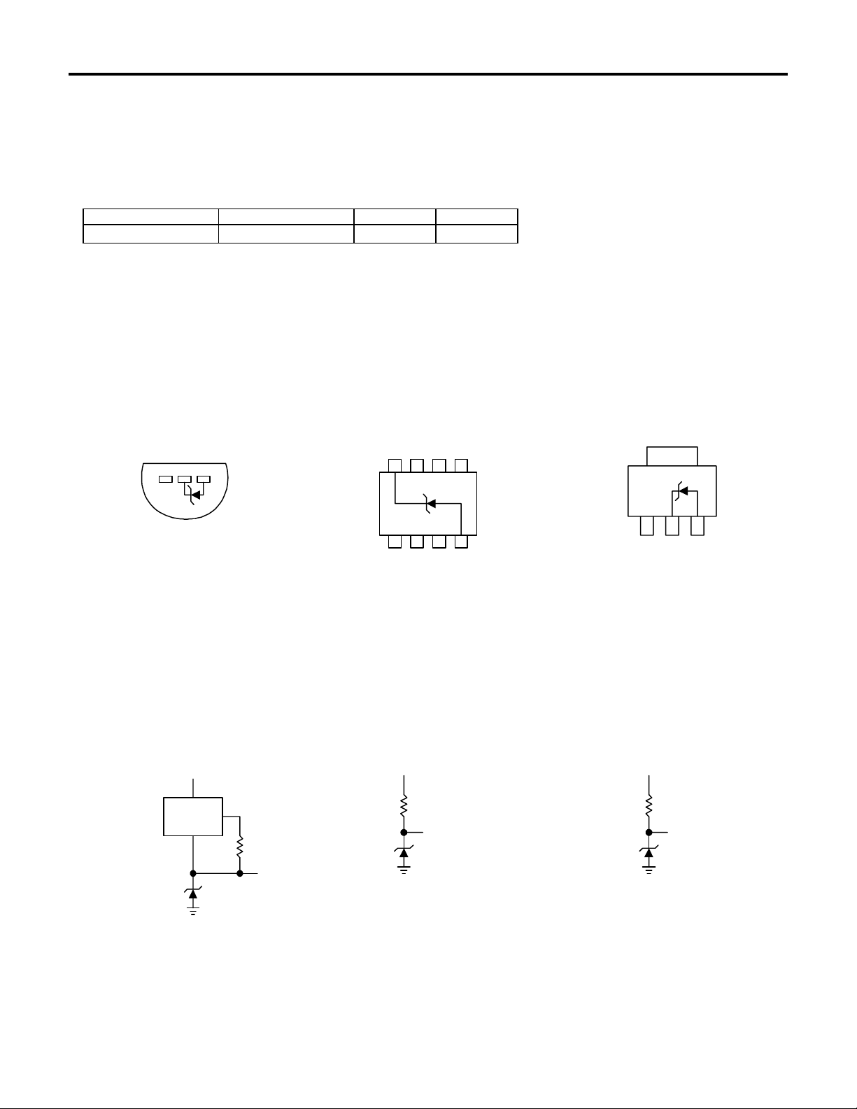
PIN CONNECTIONS
. The guaranteed specifications apply only for the test conditions listed.
max is:
j
Thermal Resistance TO-92 SO-8 SOT-89
(junction to ambient)
JA
, divided by T
170°C/W (0.125” leads) 165°C/W 160°C/W
- T
MAX
. The measured temperatures are 0°C, 25°C, 70°C, 85°C.
MIN
= TJ = 25°C.
A
TO-92 8L SOIC SOT-89
Plastic Package (N) SO Package (S) (L)
123
N/C N/CN/C
+
756
12843
N/C N/C N/C
-
N/C
123
-+
Bottom View Top View Top View
TYPICAL APPLICATIONS
Wide Input Micropower Reference Reference from
Range Reference from 9V Battery 1.5V Battery
= 2.3V TO 30V
V
IN
LM334
AMS385-1.2
4.3k
OUT
1.24V
9V
500k
1.2V
AMS385-1.2
1.5V
3k
1.2V
AMS385-1.2

http://www.BDTIC.com/AMS
TYPICAL APPLICATIONS (Continued)
0°C - 100°C Thermometer
AMS285-1.2/AMS385-1.2
Lower Power Thermometer
0°C - 100°C Thermometer
150
M
0-100
µ
I
OUT
A
LM334
+
V
-
V
R1
4k
R2
1k
R
R3
100
R4
220
AMS385-1.2
1.5V
(1.3-1.6V)†
Calibration
1. Short AMS385-1.2, adjust R3 for I
= temp at
OUT
1µA/°K
2. Remove short, adjust R2 for correct reading in
°C
† IQ at 1.3V ≅ 500 µA
I
at 1.6V ≅ 2.4mA
Q
Centigrade Thermometer Micropower* 10V Reference
*
M
8k TO
LM334
AMS385-1.2
12k†
* 2N3638 or 2N2907 select for inverse H
† Select for operation at 1.3V
≅ 600µA to 900 µA
‡ I
Q
FE
1.3 TO
1.6V‡
≅ 5
150
M
0-50
µ
I
A
OUT
LM334
+
V
-
V
R1
2k
R2
1k
R
R3
50
R4
100
AMS385-1.2
1.3-1.6V
Calibration
1. Short AMS385-1.2, adjust R3 for I
1.8µA/°K
2. Remove short, adjust R2 for correct reading in
°F
= temp at
OUT
+
1.5V†
LM334
V
-
V
1.2k
R1
1k
V1 V2
R
OUTPUT
1mV/° C
2.3k
90k 25k
27k
Calibration
1. Adjust R1 so that V1 = temp at 1mV/°K.
2. Adjust V2 to 273.2mV.
for 1.3V to 1.6V battery voltage = 50µA to 150µA
† I
Q
2.2k
AMS385-1.2
I
Q
= 15V
V
IN
1M
2
7
+
6
8
4
22M
150pF
AMS385-1.2
3
-
*I
≅ 20µA standby current
Q
10VLM4250C
3.5M
500k

http://www.BDTIC.com/AMS
TYPICAL APPLICATIONS (Continued)
Micropower Thermocouple Cold Junction Compensator
+
LM334
V
2k
1%
R
-
Precision 1µA to 1mA Current Sources
MERCURY
CELL
1.345V
THERMOCOUPLE
5.1k
1M
1%
V
+
AMS385-1.2
+
-
COLD JUNCTION
ZERO ADJ
100k
R2
ISO THERMAL
WITH LM334
R1
+
METER
-
AMS385-1.2
TC ADJ
500
AMS285-1.2/AMS385-1.2
Adjustment Procedure
1. Adjust TC ADJ pot until voltage across R1 equals Kelvin temperature
multiplied by the thermocouple Seebeck coefficient.
2. Adjust ZERO ADJ pot until voltage across R2 equals the thermocouple
Seebeck coefficient multiplied by 273.2.
Thermocouple Seebeck R1 R2 Voltage Voltage
Type Coefficient (Ω) (Ω) Across R1 Across R2
(mV/ °C) @ 25°C (mV) (mV)
J 52.3 523 1.24k 15.60 14.32
T 42.8 432 1k 12.77 11.78
K 40.8 408 953Ω 12.17 11.17
S 6.4 63.4 150Ω 1.908 1.766
Typical supply current 50µA
AMS385-1.2
30V
R1
100k
2
-
LM312
3
+
I
*
-1.5V TO -27V
OUT
150pF
-30V
C1
R1
100k
2
-
7
6
4
R2
1.5V TO 27V
I
*
OUT
LM312
3
+
C1
150pF
7
6
4
R2
*I
OUT
=1.23V/R2

http://www.BDTIC.com/AMS
TYPICAL PERFORMANCE CHARACTERISTICS
Reverse Characteristics
10
Reverse Characteristics Forward Characteristics
100
AMS285-1.2/AMS385-1.2
1.2
8
6
4
2
0
OUTPUT VOLTAGE CHANGE (mV)
-2
0.01
Reverse Dynamic Impedance
100
)
Ω
10
1
DYNAMIC IMPEDANCE (
0.1
0.01
TA =25° C
0.1 1 10 100
REVERSE CURRENT (mA)
TA =125° C
TA =-55° C
0.1 1 10 100
REVERSE CURRENT (mA)
TA =125° C
TA =25° C
TA =-55° C
A)
µ
10
TA =125° C TA =-55° C
1
REVERSE CURRENT (
0.1
1.260
1.250
1.240
1.230
REFERENCE VOLTAGE (V)
1.220
-55
TA =25° C
0
0.2
0.4 0.6
REVERSE VOLTAGE (V)
Temperature Drift of 3
Representative Units
-35 -15
5
TEMPERATURE (° C)
0.8 1.0 1.2
25 45
IR= 100µA
65 85 105
1.4
125
0.8
TA =25° C
0.4
FORWARD VOLTAGE (V)
0
10k
)
Ω
1k
100
10
1
DYNAMIC IMPEDANCE (
0.1
0.1 1 10 100
0.01
FORWARD CURRENT (mA)
Reverse Dynamic Impedance
TA =25° C
IR= 100µA
10
100
1k
FREQUENCY (Hz)
TA =-55° C
TA =125° C
10k 100k
1M
Filtered Output Noise
70
IR= 100µA
60
V)
µ
50
40
AMS385-1.2
30
20
INTEGRATED NOISE (
10
0
100 1k 10k 100k
CUTOFF FREQUENCY (Hz)
SINGLE POLE LOW PASS
100µA
OUTPUT
SHARP CUTOFF
FILTER
700
600
500
Hz)
√
400
300
NOISE (nV/
200
100
Noise Voltage
0
10
100 1k 10k 100k
FREQUENCY (Hz)
IR= 100µA
2.0
1.5
1.0
0.5
0
~
~
10
VOLTAGE SWING (V)
0
Response Time
INPUT
0
200 400 600
TIME (
OUTPUT
100k
INPUT
OUTPUT
µ
s)
~
~

http://www.BDTIC.com/AMS
AMS285-1.2/AMS385-1.2
PACKAGE DIMENSIONS inches (millimeters) unless otherwise noted.
3 LEAD TO-92 PLASTIC PACKAGE (N)
0.060±0.005
(1.524±0.127)
DIA
0.180±0.005
(4.572±0.127)
0.180±0.005
(4.572±0.127)
0.90
(2.286)
NOM
0.060±0.010
(1.524±0.254)
0.140±0.010
(3.556±0.127)
10°
NOM
N (TO-92 ) AMS DRW# 042391
0.500
(12.70)
MIN
0.050±0.005
(1.270±0.127)
0.050
(1.270)
MAX
0.016±0.003
(0.406±0.076)
UNCONTROLLED
LEAD DIMENSIONS
5° NOM
0.015±0.002
(0.381±0.051)
8 LEAD SOIC PLASTIC PACKAGE (S)
0.189-0.197*
(4.801-5.004)
87 65
0.228-0.244
(5.791-6.197)
0.150-0.157**
(3.810-3.988)
12 34
0.053-0.069
(1.346-1.752)
0.014-0.019
(0.355-0.483)
*DIMENSION DOES NOT INCLUDE MOLD FLASH. MOLD FLASH
SHALL NOT EXCEED 0.006" (0.152mm) PER SIDE
**DIMENSION DOES NOT INCLUDE INTERLEAD FLASH. INTERLEAD
FLASH SHALL NOT EXCEED 0.010" (0.254mm) PER SIDE
0.050
(1.270)
TYP
0.004-0.010
(0.101-0.254)
0.008-0.010
(0.203-0.254)
0.010-0.020
(0.254-0.508)
0.016-0.050
(0.406-1.270)
x 45°
0°-8° TYP
S (SO-8 ) AMS DRW# 042293

AMS285-1.2/AMS385-1.2
http://www.BDTIC.com/AMS
PACKAGE DIMENSIONS inches (millimeters) unless otherwise noted (Continued).
SOT-89 PLASTIC PACKAGE (L)
0.173-0.181
0.155-0.167
(3.94-4.25)
0.090-0.102
(2.29-2.60)
(4.40-4.60)
0.064-0.072
(1.62-1.83)
0.035-0.047
(0.89-1.20)
0.055-0.063
(1.40-1.60)
0.084-0.090
(2.13-2.29)
0.014-0.017
(0.35-0.44)
0.059
(1.50)
BSC
0.118
(3.00)
BSC
0.017-0.022
(0.44-0.56)
0.014-0.019
(0.36-0.48)
L (SOT-89 ) AMS DRW# 042392
 Loading...