

Diodes
z
z
z
z
z
z
z
z
Zener diode
UDZS8.2B
Applications
Constant voltage control
Features
1) Compact, 2-pin mini-mold type for
high-density mounting.(UMD2)
2) High reliability.
3) Can be mounted automatically,
using chip mounter .
Construction
Silicon epitaxialpla nar
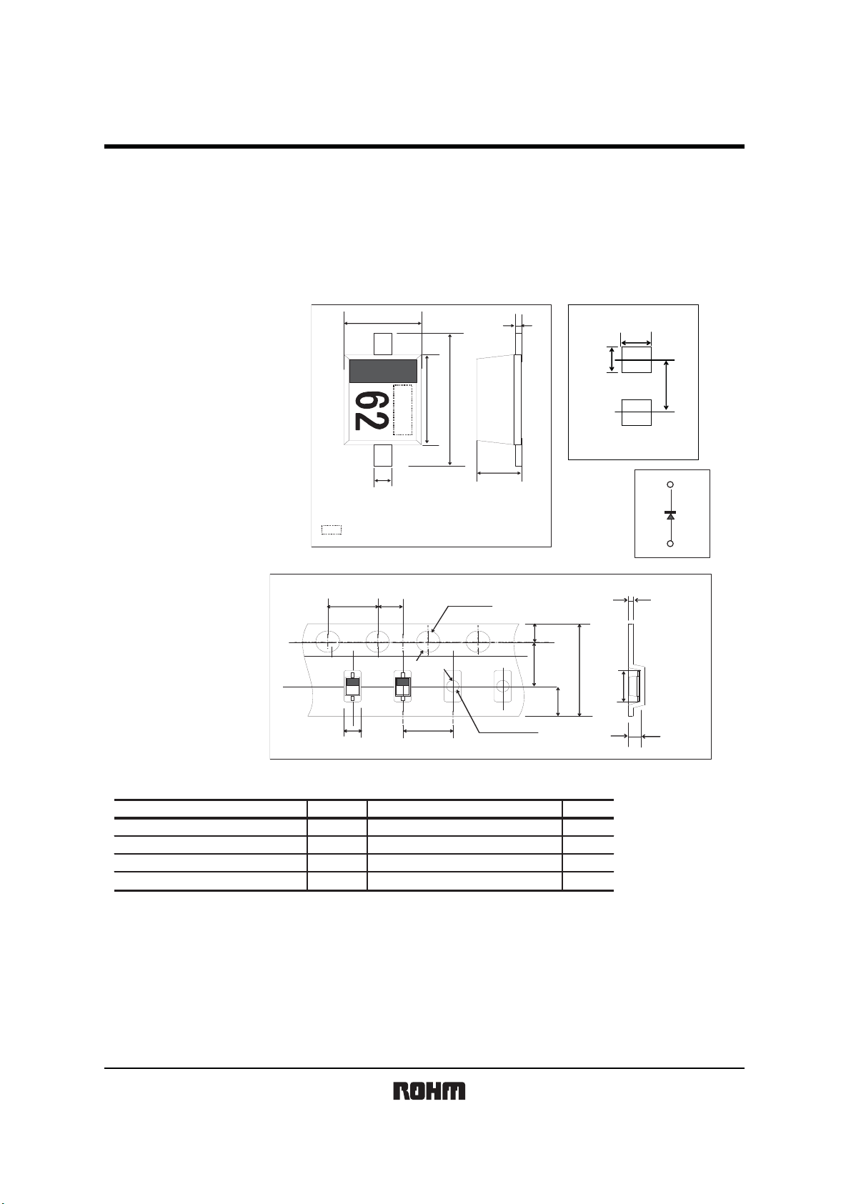
Dimensions (Unit : mm)
㩷
㪡㪜㪛㪜㪚㩷㪑㩷㪪㪇㪛㪄㪊㪉㪊
㪡㪜㪠㪫㪘㩷㪑㩷㪪㪚㪄㪐㪇㪆㪘
Tapingspecifications(Unit : mm)
㪈㪅㪉㪌㫧㪇㪅㪈
㪇㪅㪊㫧㪇㪅㪇㪌
㪩㪦 㪟㪤 㩷㪑㩷㪬㪤 㪛㪉
㪻㫆㫋㩷㩿㫐㪼㪸㫉㩷㫎㪼㪼㫂㩷㪽㪸㪺㫋㫆㫉㫐㪀
㪜㪯㪅㩷㩷㪬㪛㪱㪪 㪊㪅㪍㪙
㪇㪅㪈㫧㪇㪅㪈
䇭䇭䇭㩷㪇㪅㪇㪌
㪈㪅㪎㫧㪇㪅㪈
㪉㪅㪌㫧㪇㪅㪉
㪇㪅㪎㫧㪇㪅㪉
䇭䇭䇭㩷㪇㪅㪈
UDZS8.2B
Land size figure (Unit : mm)
0.9MIN.
0.8MIN.
2.1
UMD2
Structure
㪋㪅㪇㫧㪇㪅㪈
㪈㪅㪋㪇㫧㪇㪅㪈
Absolute maximum ratings (T a=25qC)
Parameter
ower dissipation
P
ion temperature
Junct
Storage temperature
Operating temperat ur e -55 to +150
Symbol Unit
Pm
Tj
Tstg
Topr
㪉㪅㪇㫧㪇㪅㪇㪌
㱢㪈㪅㪌㪌㫧㪇㪅㪇㪌
㪋㪅㪇㫧㪇㪅㪈 㱢㪈㪅㪇㪌
Limits
200
150
-55 to +150
㪇㪅㪊㫧㪇㪅㪈
㪈㪅㪎㪌㫧㪇㪅㪈
㪊㪅㪌㫧㪇㪅㪇㪌
㪏㪅㪇㫧㪇㪅㪉
㪉㪅㪏㫧㪇㪅㪈
㪉㪅㪎㪌
㪈㪅㪇㫧㪇㪅㪈
W
㷄
㷄
㷄
Rev.C 1/4
UDZS8.2B
z
z
Diodes
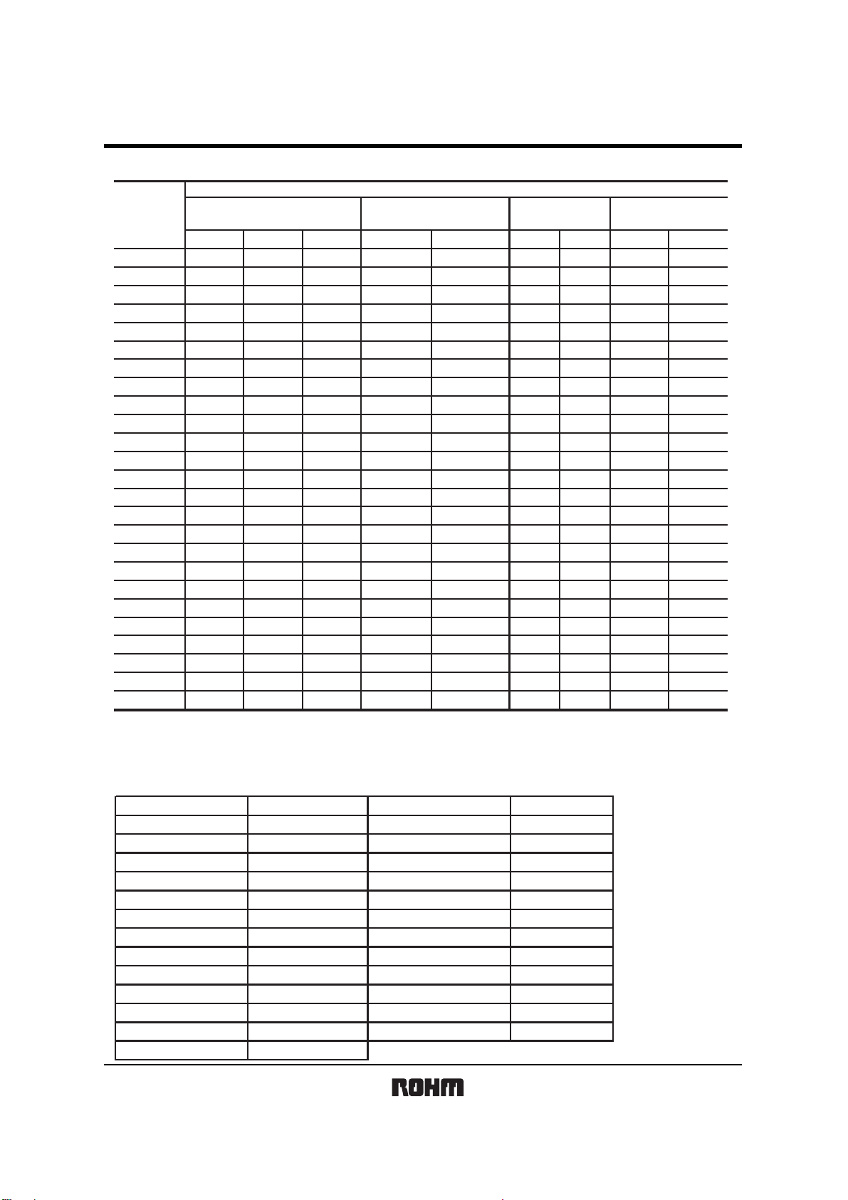
Electrical characteristics (Ta=25qC)
Symbol
TYP.
UDZS 3.6B 3.600 3.845 5.0 100 5.0 1000
DZS 3.9B 3.890 4.160 5.0 100 5.0 1000
U
UDZS 4
UDZS 4
UDZS 5
UDZS 5
UDZS 6
UDZS 6
UDZS 7
UDZS 8
UDZS 9
UDZS 1
UDZS 1
UDZS 1
UDZS 1
UDZS 1
UDZS 1
UDZS 1
UDZS 2
UDZS 2
UDZS 2
UDZS 2
UDZS 3
UDZS 3
U
(
(
.3B
.7B
.1B
.6B
.2B
.8B
.5B
.2B
.1B
0B
1B
2B
3B
5B
6B
8B
0B
2B
4B
7B
0B
3B
DZS 36B 35.070 36.870 5.0 300 5.0 300 0.5 0.1 27.0
)The zener voltage(Vz) is measured 40ms after power is suppl i ed.
ϧ
)The operating resistances(Zz,Zzk) ar e measured by superimposing a minute alternating current
Ϩ
on the regulated current(Iz)
Zener voltage䋺Vz(V)
MIN. MAX. Iz(mA) MAX. Iz(mA) MAX. Iz(mA) MAX. VR(V)
4.170 4.430
4.550 4.750
4.980 5.200
5.490 5.730
6.060 6.330
6.650 6.930
7.280 7.600
8.020 8.360
8.850 9.230
9.770 10.210
10.760 11.220
11.740 12.240
12.910 13.490
14.340 14.980
15.850 16.510
17.560 18.350
19.520 20.390
21.540 22.470
23.720 24.780
26.190 27.530
29.190 30.690
32.150 33.790
5.0
5.0
5.0
5.0
5.0
5.0
5.0
5.0
5.0
5.0
5.0
5.0
5.0
5.0
5.0
5.0
5.0 85 5.0
5.0 100 5.0
5.0 120 5.0
5.0 150 5.0
5.0 200 5.0
5.0 250 5.0
Operating resistance䋺Zz(ȍ)
100
100
80
60
60
40
30
30
30
30
30
30
37
42
50
65
5.0
5.0
5.0
5.0
5.0
5.0
5.0
5.0
5.0
5.0
5.0
5.0
5.0
5.0
5.0
5.0
Rising operataing
resistance䋺Zz(ȍ)
1.0
1.0
1000 1.0
800 0.5
500 0.5
200 0.5
100 0.5
60 0.5
60 0.5
60 0.5
60 0.5
60 0.5
60 0.5
80 0.5
80 0.5
80 0.5
80 0.5
80 0.5
100 0.5
100 0.5
120 0.5
150 0.5
200 0.5
250 0.5
Reverse current
IR(uA)
10.0
5.0
5.0
2.0
2.0
1.0
1.0
0.5
0.5
0.5
0.5
0.1
0.1
0.1
0.1
0.1
0.1
0.1
0.1
0.1
0.1
0.1
0.1
0.1
䋺
1.0
1.0
1.0
1.0
1.5
2.5
3.0
3.5
4.0
5.0
6.0
7.0
8.0
9.0
10.0
11.0
12.0
13.0
15.0
17.0
19.0
21.0
23.0
25.0
Type No.
TYPE
UDZS3.6B
UDZS3.9B
UDZS4.3B
UDZS4.7B
UDZS5.1B
UDZS5.6B
UDZS6.2B
UDZS6.8B
UDZS7.5B
UDZS8.2B
UDZS9.1B
UDZS10B
UDZS11B
㪫㪰㪧㪜䇭㪥㪦㪅
㪍㪉
㪎㪉
㪏㪉
㪐㪉
㪘㪉
㪚㪉
㪜㪉
㪝㪉
㪟㪉
㪡㪉
㪣㪉
㪇㪌
㪈㪌
TYPE
UDZS12B
UDZS13B
UDZS15B
UDZS16B
UDZS18B
UDZS20B
UDZS22B
UDZS24B
UDZS27B
UDZS30B
UDZS33B
UDZS36B
㪫㪰㪧㪜䇭㪥㪦㪅
㪉㪌
㪊㪌
㪋㪌
㪌㪌
㪍㪌
㪎㪌
㪏㪌
㪐㪌
㪘㪌
㪚㪌
㪜㪌
㪝㪌
䇭
Rev.C 2/4

Diodes
z
Electrical characteristic curves (T a=25qC)
㪈㪇
㪈
㪇㪅㪈
㪱㪜㪥㪜㪩㩷㪚㪬 㪩㪩㪜㪥㪫㪑㪠 㫑㩿㫄㪘㪀
㪌㪅㪈
㪋㪅㪎
㪇㪅㪇㪈
㪋㪅㪊
㪊㪅㪐
㪊㪅㪍
㪇㪅㪇㪇㪈
㪇 㪌 㪈㪇 㪈㪌 㪉㪇 㪉㪌 㪊㪇 㪊㪌 㪋㪇
㪌㪅㪍
㪍㪅㪏
㪍㪅㪉
㪎㪅㪌
㪏㪅㪉
㪐㪅㪈
UDZS8.2B
㪉㪋
㪈㪊
㪈㪉㪈㪈㪈㪇
㪈㪌
㪈㪏
㪈㪍
㪱㪜㪥㪜㪩㩷㪭㪦㪣㪫㪘㪞 㪜㪑㪭㫑㩿㪭㪀
㪭㫑㪄㪠㫑㩷㪚㪟㪘㪩㪘㪚㪫 㪜㪩㪠㪪㪫㪠㪚㪪
㪉㪉
㪉㪇
㪉㪎
㪊㪇
㪊㪊
㪊㪍
㪉㪌㪇
㪉㪇㪇
㪈㪌㪇
㪈㪇㪇
㪌㪇
㪧㪦㪮㪜㪩㩷㪛㪠㪪㪪㪠㪧㪘㪫㪠㪦㪥㪑㪧㪻㩿㫄㪮㪀
㪇
㪇 㪉㪌 㪌㪇 㪎㪌 㪈㪇㪇 㪈㪉㪌 㪈㪌㪇
㪘㪤㪙㪠㪜㪥㪫㩷㪫㪜㪤㪧 㪜㪩㪘㪫㪬㪩㪜㪑㪫㪸㩿㷄 㪀
㪧㪻㪄㪫㪸䇭㪚㪟㪘㪩㪘㪚㪫㪜㪩㪠㪪㪫㪠㪚㪪
㪇㪅㪈㪉
㪇㪅㪈
㪇㪅㪇㪏
㪇㪅㪇㪍
㪇㪅㪇㪋
㪇㪅㪇㪉
㪇
㪄㪇㪅㪇㪉
㪄㪇㪅㪇㪋
㪄㪇㪅㪇㪍
㪫㪜㪤㪧㪅㪚㪦㪜㪝㪝㪠㪚㪠㪜㪥㪚㪜㪑㱏㫑㩿䋦㪆㷄㪀
㪄㪇㪅㪇㪏
㪇 㪈㪇㪉㪇㪊㪇㪋㪇
㪱㪜㪥㪜㪩㩷㪭㪦 㪣㪫㪘㪞㪜䋺 㪭㫑㩿㪭㪀
㱏㫑㪄㪭㫑㩷㪚㪟㪘㪩 㪘㪚㪫㪜㪩㪠㪪㪫㪠㪚㪪
㪈㪇㪇㪇㪇
㪈㫄㫊
㪊㪇㪇㫌㫊
㪧㪩㪪㪤
㪫㪠㪤㪜㪑㫋㩿㫄㫊㪀
㫋㫀㫄㪼
㪫㪠㪤㪜㪑㫋㩿㫊㪀
㫋
㪩㫋㪿㩿㫁㪄㪸㪀
㪩㫋㪿㩿㫁㪄㪺㪀
㪈㪇㪇㪇
㪈㪇㪇
㪈㪇
㪧㪦㪮㪜㪩㪑㪧㪩㪪㪤㩿㪮㪀
㪈
㪩㪜㪭㪜㪩㪪㪜㩷㩷㩷㪪㪬㪩㪞㪜㩷㪤㪘㪯㪠㪤㪬㪤
㪇㪅㪈
㪇㪅㪇㪇㪈 㪇㪅㪇㪈 㪇㪅㪈 㪈 㪈㪇 㪈㪇㪇
㪧㪩㪪㪤㪄㪫㪠㪤 㪜㩷㪚㪟㪘㪩㪘㪚㪫㪜㪩㪠㪪㪫㪠㪚㪪
㪋㪇
㪊㪌
㪊㪇
㪉㪌
㪉㪇
㪈㪌
㪈㪇
㪌
㪇
㪄㪌
㪈㪇㪇㪇
㪈㪇㪇
㪈㪇
㪤㫆㫌㫅㫋㪼㪻㩷㫆㫅㩷㪼㫇㫆㫏㫐㩷㪹㫆㪸㫉㪻
㪫㪩㪘㪥㪪㪠㪜㪥㪫
㪫㪜㪤㪧㪅㪚㪦㪜㪝㪝㪠㪚㪠㪜㪥㪚㪜㪑㱏㫑㩿㫄㪭㪆㷄㪀
㪫㪟㪘㪜㪩㪤㪘㪣㩷㪠㪤 㪧㪜㪛㪘㪥㪚㪜㪑㪩㫋㪿 㩷㩿㷄㪆㪮 㪀
㪠㪤㪔㪈㪇㫄㪘 㪠㪝㪔㪈㪇㪇㫄㪘
㪈
㪇㪅㪈
㪇㪅㪇㪇㪈 㪇㪅㪇㪈 㪇㪅㪈 㪈 㪈㪇 㪈㪇㪇 㪈㪇㪇㪇
㪩㫋㪿㪄㫋㩷㪚㪟 㪘㪩㪘㪚㪫㪜㪩㪠㪪㪫㪠㪚㪪
Rev.C 3/4

Diodes
UDZS8.2B
㪈㪇
㪫㪸㪔㪄㪉㪌㷄
㪫㪸㪔㪉㪌㷄
㪈
㪫㪸㪔㪎㪌㷄
㪱㪜㪥㪜㪩㩷㪭㪦㪣㪫㪘㪞㪜 㪑㪭㫑㩿䌖㪀
㪇㪅㪇㪈
㪱㪜㪥㪜㪩㩷㪚㪬㪩㪩㪜㪥㪫㪑㪠㫑㩿㫄㪘㪀
㪇㪅㪇㪇㪈
㪇㪅㪈
㪏㪅㪌
㪏㪅㪋
㪏㪅㪊
㪏㪅㪉
㪏㪅㪈
㪫㪸㪔㪈㪉㪌㷄
㪎 㪎㪅㪌 㪏 㪏㪅㪌 㪐
㪱㪜㪥㪜㪩㩷㪭㪦㪣 㪫㪘㪞㪜㪑㪭㫑㩿 㪭㪀
㪭㫑㪄㪠㫑㩷㪚㪟㪘㪩㪘㪚㪫㪜㪩㪠㪪㪫㪠㪚㪪
㪏
㪘㪭㪜㪑㪏㪅㪉㪇㪍 㪭
㪭㫑㩷㪛㪠㪪㪩㪜㪪㪠㪦㪥㩷㪤㪘㪧
㪫㪸㪔㪉㪌㷄
㪠㪱㪔㪌㫄㪘
㫅㪔㪊㪇㫇㪺㫊
㪈㪇㪇
㪈㪇
㪈
㪇㪅㪈
㪇㪅㪇㪈
㪩㪜㪭㪜㪩㪪㪜㩷㪚㪬㪩㪩㪜㪥㪫㪑㪠㪩㩷㩿㫅㪘㪀
㪇㪅㪇㪇㪈
㪇㪅㪇㪇㪇㪈
㪈㪉㪊㪋㪌
㪩㪜㪭㪜㪩㪪㪜㩷㪭㪦㪣㪫㪘㪞㪜䋺㪭㪩㩿 㪭㪀
㪭㪩㪄㪠㪩㩷㪚㪟㪘㪩㪘㪚㪫㪜㪩㪠㪪㪫㪠㪚㪪
㪈
㪇㪅㪐
㪇㪅㪏
㪇㪅㪎
㪇㪅㪍
㪇㪅㪌
㪇㪅㪋
㪇㪅㪊
㪇㪅㪉
㪩㪜㪭㪜㪩㪪㪜㩷㪚㪬㪩㪩㪜㪥㪫㪑㪠㪩㩿㫅㪘㪀
㪇㪅㪈
㪇
㪘㪭㪜㪑㪇㪅㪇㪎㪋㫅㪘
㪠㪩㩷㪛㪠㪪㪩㪜㪪㪠㪦㪥㩷㪤㪘㪧
㪫㪸㪔㪈㪉㪌㷄
㪫㪸㪔㪎㪌㷄
㪫㪸㪔㪉㪌㷄
㪫㪸㪔㪄㪉㪌㷄
㪫㪸㪔㪉㪌㷄
㪭㪩㪔㪌㪅㪇㪭
㫅㪔㪊㪇㫇㪺㫊
㪈㪇㪇
㪽㪔㪈㪤㪟㫑
㪈㪇
㪫㪜㪩㪤㪠㪥㪘㪣㪪㪑㪚㫋㩿㫇㪝㪀
㪚㪘㪧㪘㪚㪠㪫㪘㪥㪚㪜㩷 㪙㪜㪫㪮㪜㪜㪥
㪈
㪇㪈㪉㪊㪋㪌
㪩㪜㪭㪜㪩㪪㪜㩷㪭㪦㪣㪫㪘㪞㪜㪑㪭㪩㩿㪭㪀
㪭㪩㪄㪚㫋㩷㪚 㪟㪘㪩㪘㪚㪫㪜㪩 㪠㪪㪫㪠㪚㪪
㪊㪇
㪉㪐
㪉㪏
㪉㪎
㪉㪍
㪉㪌
㪉㪋
㪚㪘㪧㪘㪚㪠㪫㪘㪥㪚㪜
㪉㪊
㪉㪉
㪙㪜㪫㪮㪜㪜㪥㪫㪜㪩㪤 㪠㪥㪘㪣㪪㪑 㪚㫋㩿㫇㪝㪀
㪉㪈
㪉㪇
㪘㪭㪜㪑㪉㪋㪅㪎㪌㫇㪝
㪚㫋㩷㪛㪠㪪㪩㪜㪪㪠㪦㪥㩷㪤㪘㪧
㪫㪸㪔㪉㪌㷄
㪽㪔㪈㪤㪟㫑
㪭㪩㪔㪇㪭
㫅㪔㪈㪇㫇㪺㫊
㪈㪇㪇㪇
㪈㪇㪇
㪈㪇
㪛㪰㪥㪘㪤㪠 㪚㩷㪠㪤㪧㪜㪛㪘 㪥㪚㪜㪑㪱㫑㩿㱅㪀
㪈
㪇㪅㪈 㪈 㪈㪇
㪱㪜㪥㪜㪩㩷㪚㪬㪩 㪩㪜㪥㪫㩿㫄㪘㪀
㪱㫑㪄㪠㫑㩷㪚㪟㪘㪩㪘㪚㪫㪜㪩㪠㪪㪫㪠㪚㪪
Rev.C 4/4

Appendix
Notes
No technical content pages of this document may be reproduced in any form or transmitted by any
means without prior permission of ROHM CO.,LTD.
The contents described herein are subject to change without notice. The specifications for the
product described in this document are for reference only. Upon actual use, therefore, please request
that specifications to be separately delivered.
Application circuit diagrams and circuit constants contained herein are shown as examples of standard
use and operation. Please pay careful attention to the peripheral conditions when designing circuits
and deciding upon circuit constants in the set.
Any data, including, but not limited to application circuit diagrams information, described herein
are intended only as illustrations of such devices and not as the specifications for such devices. ROHM
CO.,LTD. disclaims any warranty that any use of such devices shall be free from infringement of any
third party's intellectual property rights or other proprietary rights, and further, assumes no liability of
whatsoever nature in the event of any such infringement, or arising from or connected with or related
to the use of such devices.
Upon the sale of any such devices, other than for buyer's right to use such devices itself, resell or
otherwise dispose of the same, no express or implied right or license to practice or commercially
exploit any intellectual property rights or other proprietary rights owned or controlled by
ROHM CO., LTD. is granted to any such buyer.
Products listed in this document are no antiradiation design.
The products listed in this document are designed to be used with ordinary electronic equipment or devices
(such as audio visual equipment, office-automation equipment, communications devices, electrical
appliances and electronic toys).
Should you intend to use these products with equipment or devices which require an extremely high level
of reliability and the malfunction of which would directly endanger human life (such as medical
instruments, transportation equipment, aerospace machinery, nuclear-reactor controllers, fuel controllers
and other safety devices), please be sure to consult with our sales representative in advance.
It is our top priority to supply products with the utmost quality and reliability. However, there is always a chance
of failure due to unexpected factors. Therefore, please take into account the derating characteristics and allow
for sufficient safety features, such as extra margin, anti-flammability, and fail-safe measures when designing in
order to prevent possible accidents that may result in bodily harm or fire caused by component failure. ROHM
cannot be held responsible for any damages arising from the use of the products under conditions out of the
range of the specifications or due to non-compliance with the NOTES specified in this catalog.
Thank you for your accessing to ROHM product informations.
More detail product informations and catalogs are available, please contact your nearest sales office.
ROHM Customer Support System
www.rohm.com
THE AMERICAS / EUPOPE / ASIA / JAPAN
Contact us : webmaster@ rohm.co. jp
Copyright © 2007 ROHM CO.,LTD.
21, Saiin Mizosaki-cho, Ukyo-ku, Kyoto 615-8585, Japan
TEL : +81-75-311-2121
FAX : +81-75-315-0172
Appendix1-Rev2.0

 Loading...