

RPM7136-R series
Photo Link Module
IR Receiver Module
RPM7136-R series
RPM7136-R series are remote control receiver modules. Small-sized, light-weight, and low current consumption
modules have been achieved by using resin mold.
zCenter frequency
36.0kHz
zApplications
All household electric appliances su ch as TV, DVD, air conditioner and audio equ ipment.
zFeatures
1) Low current consumption. (0.85mA Typ.)
2) High ripple rejection.
3) 5 types of holders available for each set.
zRPM7136-R series
with holders
TOP VIEW
RSIP-A3 (H4)
9.6mm5.5mmHeight to lens
15.9mm
RPM7136-H4R
TOP VIEW
RSIP-A3 (H8)
7.2mm
RPM7136-H8R
∗Under development
TOP VIEW
RSIP-A3 (H9)
12.0mm
RPM7136-H9R
Products No.
Straight type
RSIP-A3
RPM7136-R RPM7136-V4R
L forming
RSIP-A3 V4
4.8mm
SIDE VIEW
RSIP-A3 (H13)
15.0mm
∗RPM7136-H13R
SIDE VIEW
RSIP-A3 (H5)
∗RPM7136-H5R
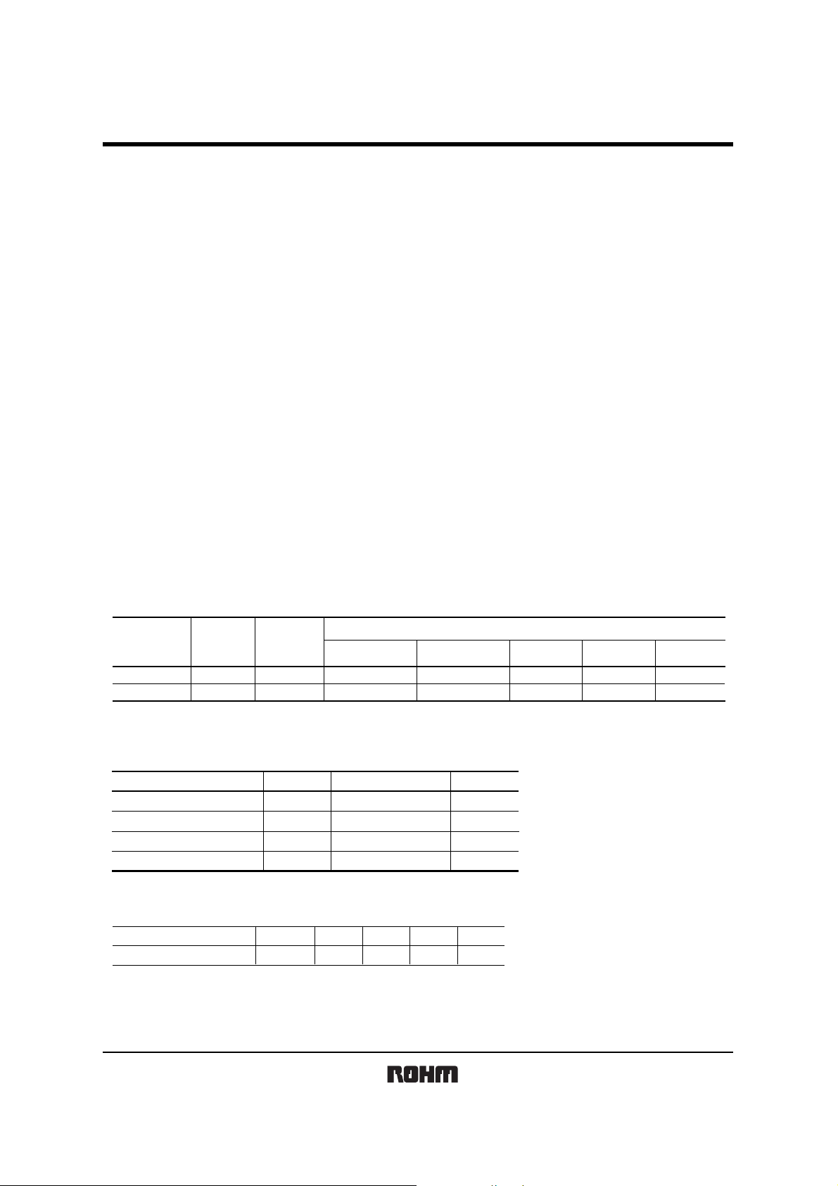
zAbsolute maximum ratings (Ta = 25°C)
Parameter Symbol
Supply Voltage V
Storage temperature
Operating temperature
CC
Tstg
Topr
Limits
6.3
−30 to +100
−10 to +75
Unit
V
mA2.0Output Current Io
°C
°C
zRecommended operating conditions (Ta = 25°C)
Parameter Symbol Min. Typ. Max. Unit
V
Supply Voltage
CC
5.0 V4.5 5.5
Rev.B 1/7
RPM7136-R series
Photo Link Module
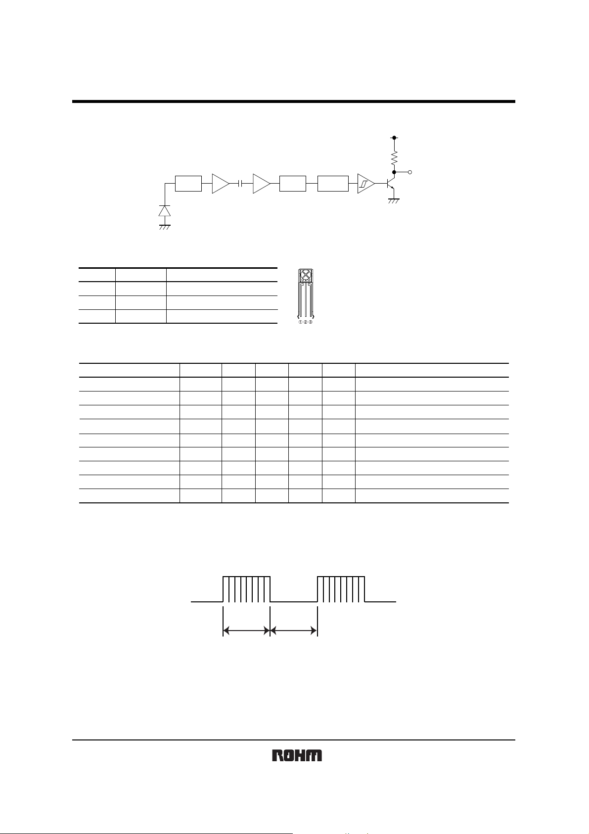
zBlock diagram
AMP
I / V BPF
ComparatorLIMITER
Detector
CC
V
22k
R
OUT
zT ermina l description
Pin namePin No. Function
1R
2
3
OUT
GND
CC
V
OUTPUT TERMINAL
GROUND
POWER SUPPLY
zElectrical, Optical characteristics (Unless otherwise noted, Ta = 25°C V
Parameter Symbol Min. Typ. Max. Unit Conditions
Consumption Current I
Effective Distance
High Level Output Voltage
Low Level Output Voltage
ON Pulse Width
OFF Pulse Width
Center frequency
Horizontal half angle
Vertical half angle
∗1 600/600µs burst wave is transmitted by standard transmitter. However, it must be measured after the initial transmission pulse is 10 pulse.
∗2 It is an angle when the linear arrival distance become half.
CC
L
V
H
V
T
ON
T
OFF
fo
θ 1/2
θ 1/2
L
−
8
4.5
−
400
400
−
−
−
0.85 mA No outside light, No signal input
1.5
15
−
−
600
0.5
800
600
36.0
45
35
−
−
CC=5V)
m−
Outer light condition Ee < 10 (Ix)
V−
V
µs
µs800
<
Isink 200µA
=
Outer light condition Ee < 10 (Ix) ∗1
Outer light condition Ee < 10 (Ix) ∗1
kHz−
deg
deg
z Measurement Conditions
(1) Transmit signal
∗1
∗1
∗1
∗2
∗2
600µs 600µs
Carrier frequency=fo, Duty=50%
Fig.1 Transmit signal
Rev.B 2/7
RPM7136-R series
Photo Link Module
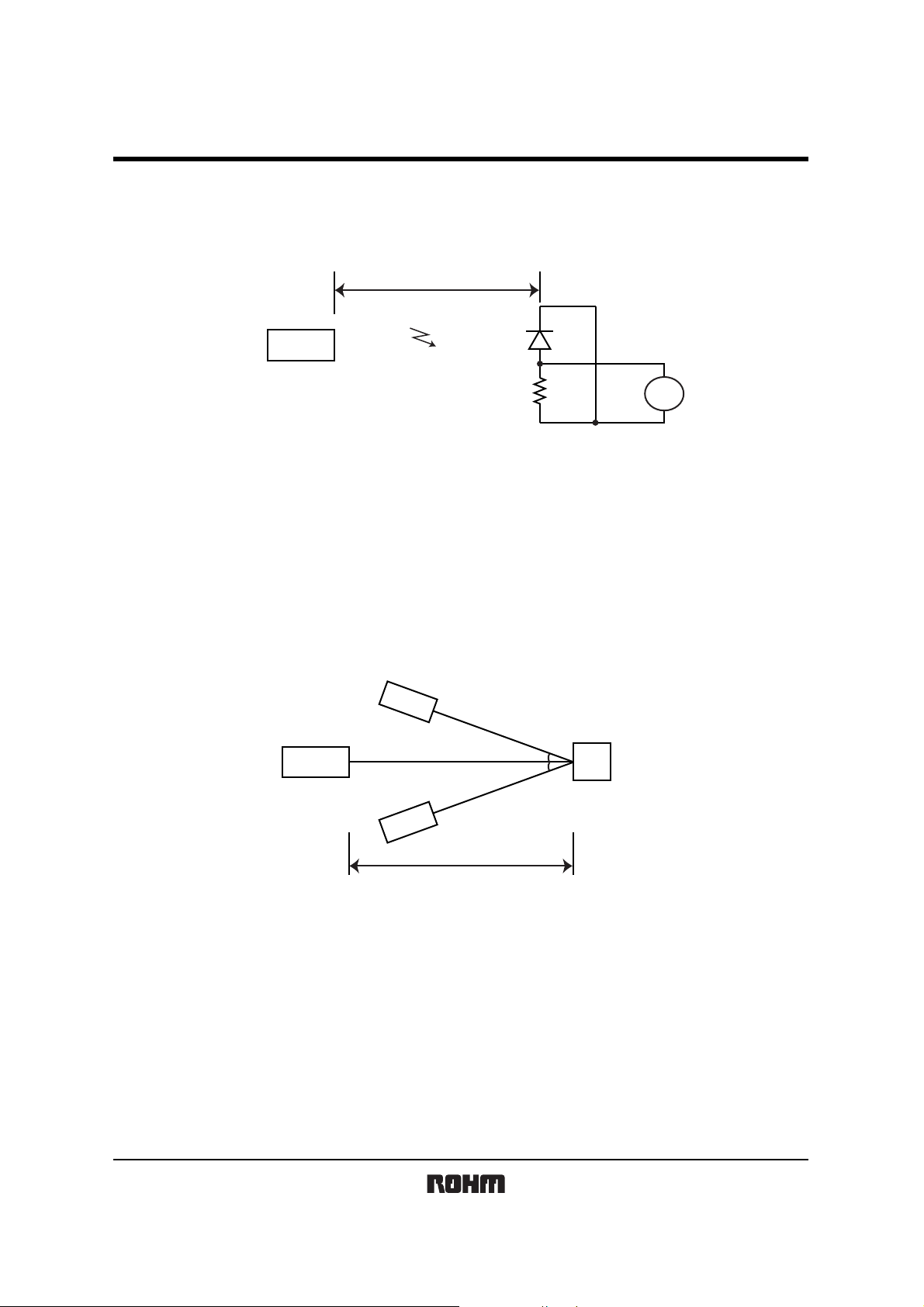
(2) Stand ard transmitter
λ peak=940nm
λ ∆=40nm
OUT
/ R
20cm
RPM-302B
io=V
Standard transmitter
Fig.2 Measurement of standard transmitter proofreading
R
V
OUT
When standard transmitter output the signal at Fig.1 standard photodiode output become io=5µAp-p under the
measurement condition Fig.2.
(The radiant intensity of standard transmitter : 50mW / sr)
RPM-302B : standard photodiode has short current Isc=27 µA at E=1000(lx)
(using CIE standard light sou rce A)
(3) Measurement effective distance, horizont al & vertical half angle
RPM7136-R series
θ
θ
Standard transmitter
Light detector face
illuminance : Ee
Effective distance : L
(θ ; Indicates horizontal and vertical directions)
Fig.3 Measurement condition for effective distance
Effective distance L : Effective distance at θ=0° Fig.3
Horizontal & vertical half angle θ : The angle which effective distance became 50% of L.
Rev.B 3/7

RPM7136-R series
Photo Link Module
(4) Output signal
Transmit signal
Output signal
600µs
T
ON
Fig.4
600µs
T
OFF
(5) Measurement circuit for the output voltage and the consumption current
V
CC
I
CC
A
Carrier frequency=f
Carrier Duty=50%
V
CC
V
H
CC
1/2 V
V
L
GND
0
R
OUT
V
RPM7136-R
GND
Fig.5
V
V
H
, V
L
CC
Rev.B 4/7

RPM7136-R series
Photo Link Module
zHow to use the receiver without holder
Please use the receiver with shield case or shield plate as an EMI noise measures.
(Shield case and shield plate are required to be grounded.)
Because internal or external noise (CRT, fluorescent tube, motor, LCD backlight) of the receiver may caus e malf unctio n
like a reduced effective distance.
(In the case of internal and external noise are strong, please use RPM7136-HxR series with holder.)
zNotes
(1) All characteristics of th e receiver in this s pecification are s pecified by sup plying burst wave form (Fig. 1) with ROHM
standard transmitter (Fig.2 ).
If in case of other burst wave form w ill be used, p lease check th ese spec. Ca refully under the evaluations.
(2) When the receiver will be used as the w ire-less remote controller, please use the signal method the signal method the
signal format which refer to “Measures to prevent malfunctioning of IR remote-controlled electric home appliances”.
(Published July 1987 by Associa tion of Elec tric H ome Appl iances) Oth er examples for suit able signal format are RC5
Code, RC6 Code, RCMM Code. If using other signal method, signal format, (ex: signal format which not including the
leader signal) the receiver might have chances to miss-function.
(3) Please set up transmitter’s carrier frequency as same as the receiver’s f
occurred.
(4) If transmission signal has non-continues carrie r , error might be occurred . Continuous carrier is nece ssary.
0 frequency. Otherwise error might be
T1
T1≠T2
T2
(5) The receiver was designed to use as in-door use only.
Therefore, please understand that the receiver cannot cover all characteristics, in case of using it out-door.
(6) Noise environment (Light noise from inverter Lamp, and other kind of Lamps, Power ripple, electromagnetic noise from
power circuit, and etc) may cause a reduced effective distance.
(7) The receiver may not w ork properly if re ceiving signal judgem ent is done by single pulse due to the
surrounding / environmental noises.
To preven t such misjudgement, please ma ke sure that the rece iver is set up to w ork only when receiving
series of coded signal.
(8) Emitting unit (remote control transmitter) has to be considered about its emitting device function, characteristics and
characteristics of the receiver.
(9) Please connect ‘Holder’ on to the ‘Ground (GND)’ of PCB. If the holder is not connected to the GND, there is a
possibility of worsening the characteristics of product.
(10) Do not supply unnecessary stress to lead.
(11) Please pay careful attention to the lens.
It might have a chance to miss-function when the lens get dust or dirty. And also please do not touch the lens.
(12) In order to prevent products from ESD, human body and solder iron, etc. are required to be grounded.
Rev.B 5/7

RPM7136-R series
Photo Link Module
zElectrical and optical characteristics curves
0.00
−2.00
−4.00
120
100
80
60
Gain : (dB)
−6.00
−8.00
−10.00
−4 −3 −2 −1fo+1 +2 +3 +4
Frequency : (kHz)
Fig.6 BPF characteristic
40
20
Rerative sensitivity : (%)
0
700 750 800 850 900 950 1000 1050 1100 1150 1200
Wave length : λ (nm)
Fig.7 Optical bandwidth of the
photo-diode encapsulation
100
80
60
40
100
80
60
40
20
Relative effective distance : (%)
0
−80 −60 −40 −20 0 20 40 60 80
Angle : (˚)
Fig.8 Direction characteristic
(Horizontal direction)
20
Relative effective distance : (%)
0
−80 −60 −40 −20 0 20 40 60 80
Angle : (˚)
Fig.9 Direction characteristic
(Vertical direction)
Rev.B 6/7
RPM7136-R series
Photo Link Module
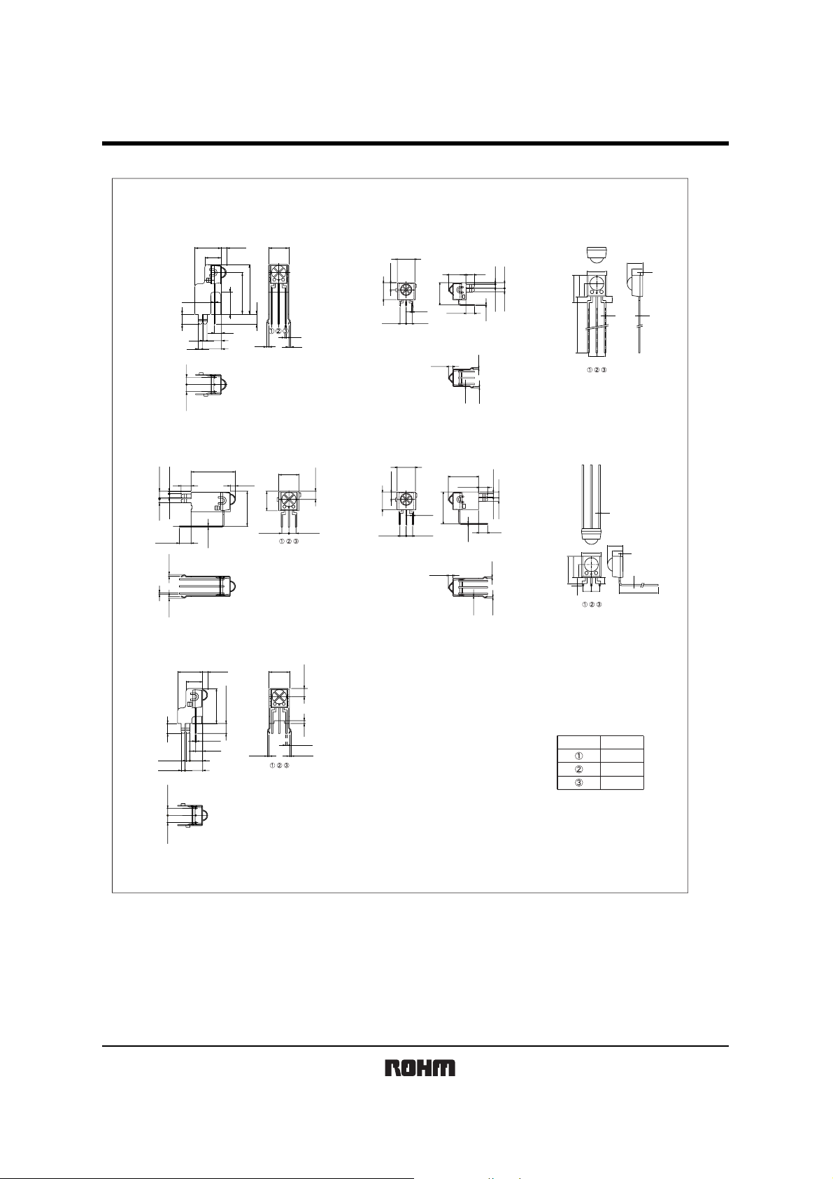
zDimensions (Unit : mm)
9.0
6.0
0.4
3.6
1.4 4.6
1.4 6.3
2.542.54
2.5
RSIP-A3 (H13)
1.8
7.95
7.3
17.95
15.0
3.6
0.5
0.6
0.6
7.30
2.95
7.00
123
2.54 2.54
4.8
3.2
6.5
9.0Max.
22Min.
6.0
4.0
123
2.54
2.54
3.607.20
0.651.40
2.351.40
9.25
0.50
3.60
0.40
1.80
0.60
0.30
0.60
0.8
1.5
0.4
0.5
RSIP-A3 (H8) RSIP-A3
15.9
3.6
2.35
0.65
1.4
1.4
4.2
0.60.6
0.5
1.8
0.4
7.3
2.95
7.0
12.65
2.542.54
RSIP-A3 (H4) RSIP-A3 (H9)
1.89.0
6.0
3.6
12.55
3.6
0.4
2.5
4.61.4
1.4
6.3
2.542.54
7.3
2.95
1.0
0.5
0.60.6
7.30
2.95
7.00
123
2.54 2.54
12.00
3.60
2.35
6.5
9.0Max.
0.5
4.8
3.2
6.0
0.8
4.0
312
0.4
1.5
2.5
20.0min
2.542.54
0.50
12.65
1.80
1.40
1.40 0.65
3.60
0.40
0.60
0.60
0.30
RSIP-A3 V4
Pin No.
Rout
GND
V
CC
RSIP-A3 (H5)
Rev.B 7/7

Appendix
No technical content pages of this document may be reproduced in any form or transmitted by any
means without prior permission of ROHM CO.,LTD.
The contents described herein are subject to change without notice. The specifications for the
product described in this document are for reference only. Upon actual use, therefore, please request
that specifications to be separately delivered.
Application circuit diagrams and circuit constants contained herein are shown as examples of standard
use and operation. Please pay careful attention to the peripheral conditions when designing circuits
and deciding upon circuit constants in the set.
Any data, including, but not limited to application circuit diagrams information, described herein
are intended only as illustrations of such devices and not as the specifications for such devices. ROHM
CO.,LTD. disclaims any warranty that any use of such devices shall be free from infringement of any
third party's intellectual property rights or other proprietary rights, and further, assumes no liability of
whatsoever nature in the event of any such infringement, or arising from or connected with or related
to the use of such devices.
Upon the sale of any such devices, other than for buyer's right to use such devices itself, resell or
otherwise dispose of the same, no express or implied right or license to practice or commercially
exploit any intellectual property rights or other proprietary rights owned or controlled by
ROHM CO., LTD. is granted to any such buyer.
Products listed in this document are no antiradiation design.
Notes
The products listed in this document are designed to be used with ordinary electronic equipment or devices
(such as audio visual equipment, office-automation equipment, communications devices, electrical
appliances and electronic toys).
Should you intend to use these products with equipment or devices which require an extremely high level of
reliability and the malfunction of with would directly endanger human life (such as medical instruments,
transportation equipment, aerospace machinery, nuclear-reactor controllers, fuel controllers and other
safety devices), please be sure to consult with our sales representative in advance.
About Export Control Order in Japan
Products described herein are the objects of controlled goods in Annex 1 (Item 16) of Export Trade Control
Order in Japan.
In case of export from Japan, please confirm if it applies to "objective" criteria or an "informed" (by MITI clause)
on the basis of "catch all controls for Non-Proliferation of Weapons of Mass Destruction.
Appendix1-Rev1.1
 Loading...