

Page 1
查询MCR03供应商
MCR03
Resistors
Thick film rectangular resistors
MCR03 (1608 size)
!Features
1) Power rating of 1 / 10W
2) Highly reliable chip resistor
Ruthenium oxide dielectric offers superior resistance to the element s.
3) Electrodes not corroded by soldering
Thick film makes the electrodes very strong.
4) Resin protective coating for FX, D resistors
Absorbs impact, facilitates mounting.
5) ROHM resistors have approved ISO–9001 certification.
Design and specifications are subject to change without notice. Carefully check the specification sheet supplied with the
product before using or ordering it.
!Ratings
Item Conditions Specifications
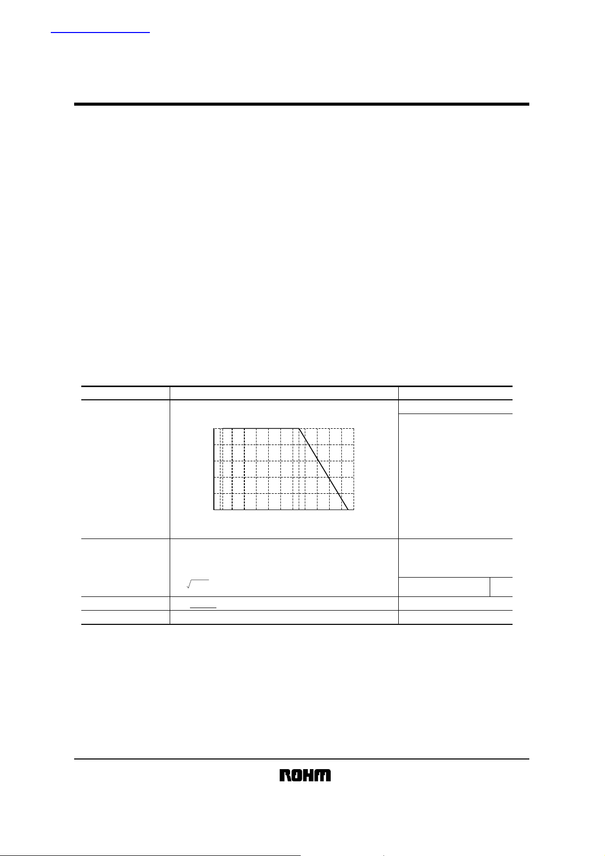
Rated power
Rated voltage
Nominal resistance See Table 1.
Operating temperature
Power must be derated according to the power derating curve in
Figure 1 when ambient temperature exceeds 70°C.
The voltage rating is calculated by the following equation.
If the value obtained exceeds the limiting element voltage,
the voltage rating is equal to the maximum operating voltage.
E= P×R
100
80
60
40
POWER LOAD (%)
20
0
−55 0 70 100 125 155
AMBIENT TEMPERATURE (°C)
Fig.1
E: Rated voltage (V) P: Rated power (W)
R: Nominal resistance (Ω)
0.10W (1 / 10W)
C
at 70°
Limiting element voltage 50V
−55°C to +155°C
1/5
Page 2
MCR03
Resistors
Jumper type
Resistance
Rated current
Operating temperature
!Before using components in circuits where they will be exposed to transient s such as pulse loads (short–duration, high– level loads), be certain to evaluate the
component in the mounted state. In addition, the reliability and performance of this component cannot be guaranteed if it is used with a steady state voltage that
is greater than its rated voltage.
!
Characteristics
Resistance
Variation of resistance
with temperature
Overload
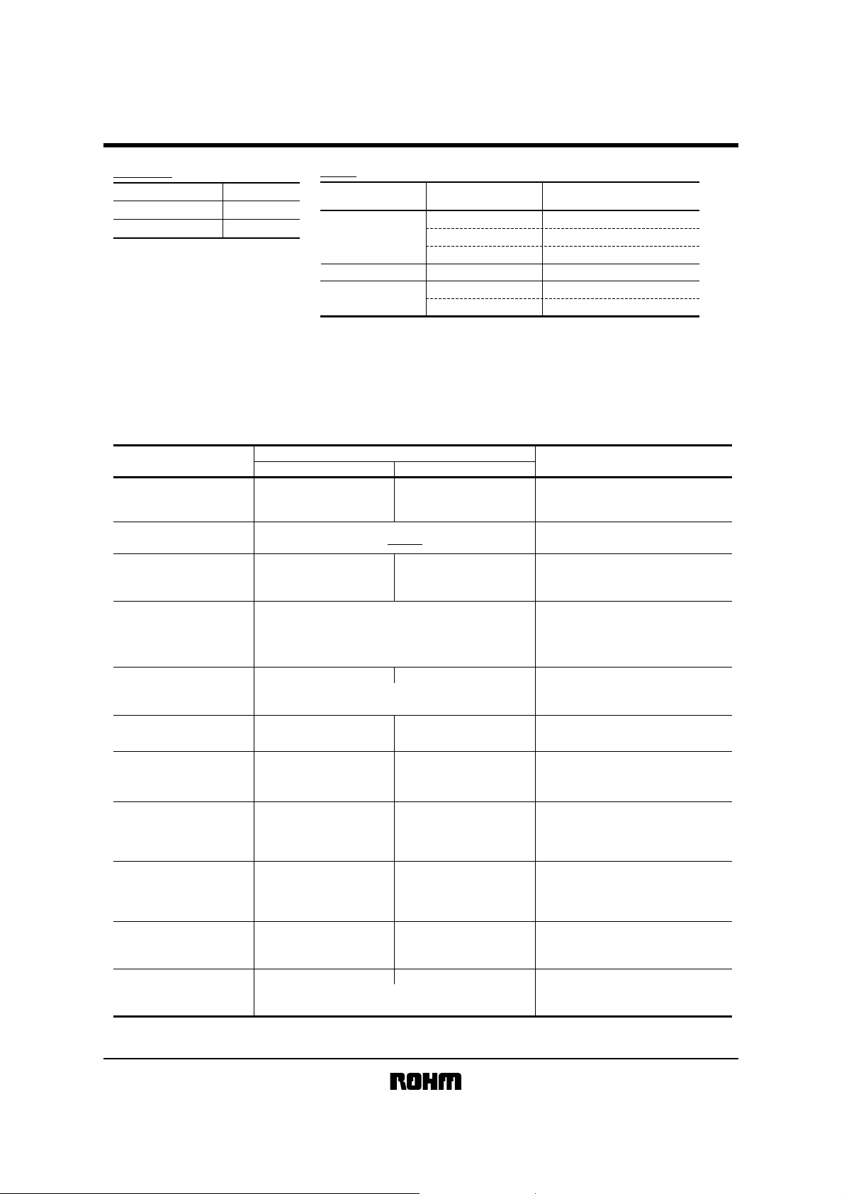
Table 1
Max. 50mΩ
1A
−55°C to +155°C
Resistance tolerance
J (±5%)
FX (±1%) (EZP type)
D (±0.5%) (EZP type)
Resistance range
(Ω)
1.0 ≤ R < 2.2 500±350
2.2 ≤ R < 10 ±500
10 ≤ R ≤ 2.2M
10 ≤ R < 100 ±100
(E24)
(E24)
(E24)
(E24,96)
(E24)
(E24)
Resistance temperature coefficient
(ppm/°C)
±20010 ≤ R ≤ 10M
±100
±50100≤ R ≤ 1M
Item Test conditions (JIS C 5201-1)
Resistor type
J : ±5%
FX : ±1%
D : ±0.5%
± (2.0%+0.1Ω) Max. 50mΩ
Guaranteed value
Max. 50mΩ JIS C 5201-1 4.5
See Table.1
Jumper type
JIS C 5201-1 4.8
Measurement : −55 / +25 / +125°C
JIS C 5201-1 4.13
Rated voltage (current) ×2.5, 2s.
Limiting element voltage ×2 : 100V
Solderability
Resistance to
soldering heat
Rapid change of
temperature
Damp heat, steady state
Endurance at 70°C
Endurance
Resistance to solvent
Bend strength of
the end face plating
A new uniform coating of minimum of
95% of the surface being immersed
and no soldering damage.
± (1.0%+0.05Ω)
No remarkable abnormality on the appearance.
± (1.0%+0.05Ω)
± (3.0%+0.1Ω)
± (3.0%+0.1Ω)
± (3.0%+0.1Ω)
± (1.0%+0.05Ω)
± (1.0%+0.05Ω)
Without mechanical damage such as breaks.
Max. 50mΩ
Max. 50mΩ
Max. 100mΩ
Max. 100mΩ
Max. 100mΩ
Max. 50mΩ
Max. 50mΩ
JIS C 5201-1 4.17
Rosin·Ethanol (25%WT)
Soldering condition : 235±5
Duration of immersion : 2.0±0.5s.
JIS C 5201-1 4.18
Soldering condition : 260±5
Duration of immersion : 10±1s.
JIS C 5201-1 4.19
Test temp. : −55
JIS C 5201-1 4.24
°C, 93%RH
40
Test time : 1,000h~1,048h
JIS C 5201-1 4.25.1
Rated voltage (current), 70
1.5h : ON − 0.5h : OFF
Test time : 1,000h~1,048h
JIS C 5201-1 4.25.3
°C
155
Test time : 1,000h~1,048h
JIS C 5201-1 4.29
°C
, Immersion cleaning, 5±0.5min.
23±5
Solvent : 2-propanol
JIS C 5201-1 4.33
°C
~+125°C 5cyc
°C
°C
°C
2/5
Page 3

Resistors
!External dimensions (Units : mm)
MCR03
1
0.3±0.2
2
3
0.3±0.2
1.6±0.1
5
(J) (FX, D)
4
0.45±0.1
0.8±0.1
6
!
Packaging
Reel Taping
ABD
0 2
0 4
0 6
0 2
0 4
0 6
0 8
C
Label
0 8
EIAJ ET-7200A compliant
Thick paper
mount
No.
Thick dielectric glaze of ruthenium
1
(only silver used for jumper)
2
Thick film of palladium-silver for primary electrode
3
Nickel-coated secondary electrode
4
External electrode coated with Sn/Pb or Sn
5
Alumina substrate
6
Overcoating (J : glass, FX, D : resin)
Heat crimp cover/Tape
(Underside paper tape) Chip resistor Square punchout hole
Material
P
0
P
2
P
1
φD
0
B
0
A
0
WFEA0B
8.0±0.3 3.5±0.05 1.75±0.1 1.1±0.1 1.9±0.1
D
φ1.5
0
+0.1
P
0
P
4.0±0.1 4.0±0.1 2.0±0.05
0
1
P
2
E
F
(Units : mm)
0
T
2
Max. 1.1
W
2
T
Bulk case
(Units : mm)
ABCD
φ180
0
φ60
−3
+1
+1.0
9
0
±
0.2
φ13
0
Shutter
EIAJ ET-7201A compliamt
Slider
110±0.7
12±0.1
36
0
−0.2
(Units: mm)
3/5
Page 4

Resistors
!Part designation
3-digit or 4-digit IEC coding system
Nominal resistancePart No.
MCR03
Packaging / Processing specifications Resistance tolerance
Part No.
Code Packaging
MCR03 EZH
EZP
PZHI
!Dimensions
1.80
1.75
1.70
1.65
(mm)
1.60
1.55
LENGTH
1.50
1.45
1.40
1 10 100 1k 10k 100k 1M 10M
JIS C 5201-1 4.4.2
SAMPLE SIZE : n=20pcs
MICROMETER
RESISTANCE
Fig.2 Dimensions (length)
!
Electrical characteristics
6.0
4.0
(%)
2.0
0
−2.0
DC RESISTANCE
−4.0
−6.0
1 10 100 1k 10k 100k 1M 10M
JIS C 5201-1 4.5
SAMPLE SIZE : n=20pcs
20°C 65%RH
RESISTANCE
Fig.5 Resistance
Paper tape
Bulk case
(Ω)
(Ω)
Standard ordering
unit(pcs)
5,000
5,000
25,000
1.00
0.95
0.90
0.85
(mm)
0.80
0.75
WIDTH
0.70
0.65
0.60
900
700
500
300
100
−100
−300
−500
−700
TEMPERATURE COEFICIENT (ppm / °C)
−900
±5%J
Specify "J" for jumper also.
JIS C 5201-1 4.4.2
SAMPLE SIZE : n=20pcs
MICROMETER
1 10 100 1k 10k 100k 1M 10M
RESISTANCE
±1%
F
D
(Ω)
Fig.3 Dimensions (width)
JIS C 5201-1 4.8
SAMPLE SIZE : n=10pcs
25°C / −55°C
25°C / 125°C
1 10 100 1k 10k 100k 1M 10M
RESISTANCE
(Ω)
Fig.6 Variation of resistance with
temperature
±0.5%
Resistance temperature
coefficient
±100(ppm/°C)X
See table.1
Blank
0.65
0.60
0.55
0.50
(mm)
0.45
0.40
THICKNESS
0.35
0.30
0.25
1 10 100 1k 10k 100k 1M 10M
JIS C 5201-1 4.4.2
SAMPLE SIZE : n=20pcs
MICROMETER
RESISTANCE
Fig.4 Dimensions (thickness)
5.0
4.0
3.0
2.0
1.0
(%)
0
∆R/R
−1.0
−2.0
−3.0
−4.0
−5.0
1 10 100 1k 10k 100k 1M 10M
JIS C 5201-1 4.13
SAMPLE SIZE : n=10pcs
RATED VOLTAGE ×2.5
TIMES : 2s
LIMITING ELEMENT VOLTAGE×2 : 100V
RESISTANCE
Fig.7 Overload
(Ω)
(Ω)
4/5
Page 5

Resistors
2.0
1.5
1.0
0.5
(%)
0
∆R/R
−0.5
−1.0
−1.5
−2.0
1 10 100 1k 10k 100k 1M 10M
Fig.8 Resistance to soldering heat
JIS C 5201-1 4.18
SAMPLE SIZE : n=10pcs
SOLDERING CONDITION : 260°C 10s
RESISTANCE
(Ω)
4.0
3.0
2.0
1.0
(%)
0
∆R/R
−1.0
−2.0
−3.0
−4.0
1 10 100 1k 10k 100k 1M 10M
JIS C 5201-1 4.25.1
SAMPLE SIZE : n=10pcs
70°C 1,000h
OVERLOAD : THE RATED VOLTAGE
RESISTANCE
(Ω)
Fig.11 Endurance at 70°C
2.0
1.5
1.0
0.5
(%)
0
∆R/R
−0.5
−1.0
−1.5
−2.0
1 10 100 1k 10k 100k 1M 10M
JIS C 5201-1 4.33
SAMPLE SIZE : n=10pcs
ENDURANCE WITH 90mm WIDTH
RESISTANCE
(Ω)
Fig.14 Bend strength of
the end face plating
MCR03
2.0
1.5
1.0
0.5
(%)
0
∆R/R
−0.5
−1.0
−1.5
−2.0
1 10 100 1k 10k 100k 1M 10M
JIS C 5201-1 4.19
SAMPLE SIZE : n=10pcs
−55°C / 125°C 5cyc.
RESISTANCE
(Ω)
Fig.9 Rapid change of
4.0
3.0
2.0
1.0
(%)
0
∆R/R
−1.0
−2.0
−3.0
−4.0
1 10 100 1k 10k 100k 1M 10M
JIS C 5201-1 4.24
SAMPLE SIZE : n=10pcs
40°C 93%RH WITH NO LOAD 1,000h
RESISTANCE
(Ω)
Fig.10 Damp heat, steady state
temperature
4.0
3.0
2.0
1.0
(%)
0
∆R/R
−1.0
−2.0
−3.0
−4.0
1 10 100 1k 10k 100k 1M 10M
JIS C 5201-1 4.25.3
SAMPLE SIZE : n=10pcs
155°C WITH NO LOAD 1,000h
RESISTANCE
(Ω)
Fig.12 Endurance
2.0
1.5
1.0
0.5
(%)
0
∆R/R
−0.5
−1.0
−1.5
−2.0
1 10 100 1k 10k 100k 1M 10M
JIS C 5201-1 4.29
SAMPLE SIZE : n=10pcs
IPA, 5min.
RESISTANCE
(Ω)
Fig.13 Resistance to solvents
5/5
 Loading...