

Page 1
A
l
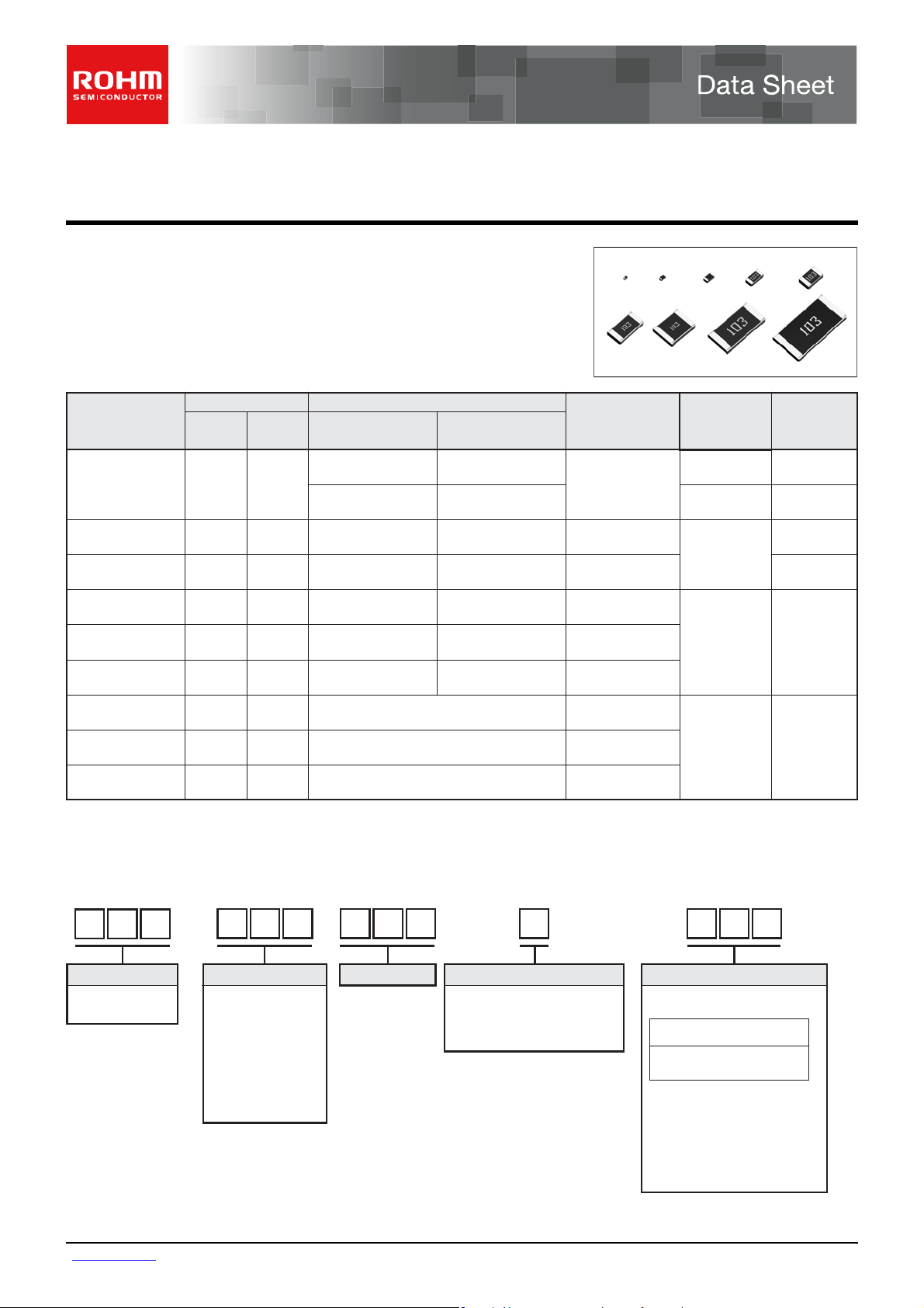
Thick Film Chip Resistors
MCR Series < General Purpose >
Features
1) Full line up from ultra small size (01005) to 2512 with jumper type.
2) High reliability metal glazed thick film.
3) ROHM resistors have obtained ISO9001/ISO/TS16949 certification.
4) "Automotive" product is AEC-Q200 compliant.
Part No.
MCR004
(mm)
0402
Size
(inch)
01005 10Ω to 3MΩ
GENERAL PURPOSE
Type Code
AUTOMOTIVE
∗Corresponds to
AEC−Q200
YZP 15,000
RZP
Resistance Range
−
−
Packing
Specification
Paper tape
(2mm pitch)
Embossed tape
(1mm pitch)
Quantity / Ree
40,000
MCR006
MCR01
MCR03
MCR10
MCR18
MCR25
MCR50
MCR100
0603
1005
1608
2012
3216
3225
5025
6432
0201
0402
0603
0805
1206
1210 JZH
2010
2512
YRT
MRT
ERT
ERT
ERT
JZH
JZH
YZP
MZP
EZP
EZP
EZP
∗Please contact us for status of AEC-Q200 on "General purpose" products.
Part Number Description
06
CMR
Part No.
MCR
(Micro chip resistors)
Size
004 (0402 [01005])
006 (0603 [0201])
01 (1005 [0402])
03 (1608 [0603])
10 (2012 [0805])
18 (3216 [1206])
25 (3225 [1210])
50 (5025 [2010])
100 (6432 [2512])
0 YTR
(mm [inch])
Type Code
Resistance Tolerance Nominal Resistance
D ( ±0.5% )
F ( ±1% )
FX ( ±1% )
J ( ±5% )
∗Only MCR03EZP
(Including jumper type)
1Ω to 10MΩ
1Ω to 10MΩ
1Ω to 10MΩ
1Ω to 10MΩ
1Ω to 10MΩ
1Ω to 3.3MΩ
1Ω to 560kΩ
1Ω to 100kΩ
Paper tape
(2mm pitch)
Paper tape
(4mm pitch)
Embossed tape
(4mm pitch)
J01 0
Resistance code, 3 or 4 digits.
000 denotes jumper type.
Resistance
tolerance
D,FJ::4 digits
Ex.)
1Ω = 1R0 ( ±5% )
9.1 Ω = 9R1 ( ±5%
10 Ω = 10R0 ( ±0.5%,±1% )
100 ( ±5% )
2.2M Ω = 2204 ( ±1% )
225 ( ±5% )
Resistance
code
3 digits
15,000
10,000
5,000
4,000
)
www.rohm.com
1/6
c
○
2012 ROHM Co., Ltd. All rights reserved.
2012.03 - Rev.
Page 2
A
Data Sheet MCR series < General Purpose >
Products List
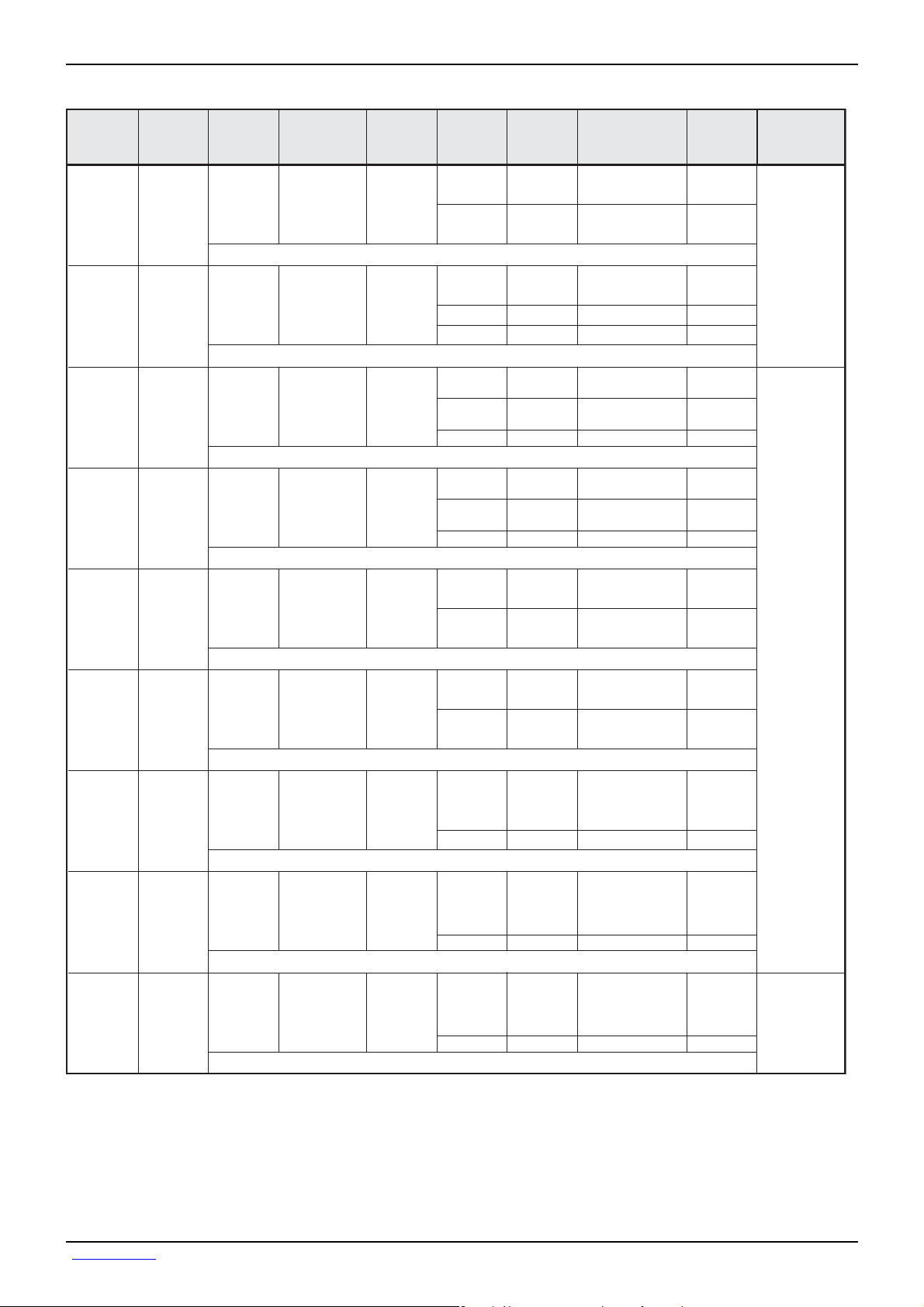
MCR004
Type Code
YZP,
RZP
Rated Power
(70
Limiting Element
°C)
(W)
0.031 15
Voltage
(V)
Maximum
Overload
Voltage
(V)
−
Temperature
Coefficient
(ppm / °C)
±300
±250
±300
±250
Resistance
Tolerance
(%)
J(±5%)
F(±1%)
Resistance Range SeriesPart No.
10Ω to 91Ω
100Ω to 3MΩ
10Ω to 91Ω
100Ω to 3MΩ
E24
E24
E24
E24
Jumper type : Rmax = 50m Ω / Imax. = 0.5A
MCR006 YRT
0.05
25
−
±600 / −200
±250
±250
±200
J(±5%)
F(±1%)
D(±0.5%)
1.0Ω to 9.1Ω
10Ω to 10MΩ
10Ω to 10MΩ
10Ω to 1MΩ
E24
E24
E24
E24
Jumper type : Rmax = 50m Ω / Imax. = 0.5A
MCR01
MRT
0.063
50
−
+500 / −250
±200
±100
±200
±100
J(±5%)
F(±1%)
D(±0.5%)
1.0Ω to 9.1Ω
10Ω to 10MΩ
10Ω to 976kΩ
1MΩ to 2.2MΩ
10Ω to 1MΩ
E24
E24
E24,E96
E24,E96
E24
Jumper type : Rmax = 50m Ω / Imax. = 1A
E24
E24
E24,E96
E24,E96
E24,E96
MCR03
ERT
0.1
50
100
±400
±200
±100
±200
±100
J(±5%)
F(±1%)
D(±0.5%)
1.0Ω to 9.1Ω
10Ω to 10MΩ
10Ω to 976kΩ
1MΩ to 10MΩ
10Ω to 1MΩ
Jumper type : Rmax = 50m Ω / Imax. = 1A
E24
E24
E24,E96
E24,E96
MCR10
ERT
0.125
150
200
±400
±200
±100
±200
J(±5%)
F(±1%)
1.0Ω to 9.1Ω
10Ω to 10MΩ
10Ω to 976kΩ
1MΩ to 2.2MΩ
Jumper type : Rmax = 50m Ω / Imax. = 2A
E24
E24
E24,E96
E24,E96
MCR18
ERT
0.25
200
400
±400
±200
±100
±200
J(±5%)
F(±1%)
1.0Ω to 9.1Ω
10Ω to 10MΩ
10Ω to 976kΩ
1MΩ to 2.2MΩ
Jumper type : Rmax = 50m Ω / Imax. = 2A
E24
E24
E24
E24,E96
MCR25
JZH
0.25
200
400
500±350
±500
±200
±100
J(±5%)
F(±1%)
1.0Ω to 2.0Ω
2.2Ω to 5.1Ω
5.6Ω to 3.3MΩ
10Ω to 1MΩ
Jumper type : Rmax = 50m Ω / Imax. = 2A
MCR50
JZH
0.5
200
400
500±350
±500
±200
±350
±100
J(±5%)
F(±1%)
1.0Ω to 2.0Ω
2.2Ω to 9.1Ω
10Ω to 330kΩ
360kΩ to 560kΩ
10Ω to 180kΩ
E24
E24
E24
E24
E24,E96
Jumper type : Rmax = 50m Ω / Imax. = 3A
MCR100
JZH
500±350
±500
1
200 400
±350
±200
±100
J(±5%)
F(±1%)
1.0Ω to 2.0Ω
2.2Ω to 9.1Ω
10Ω to 22Ω
24Ω to 100kΩ
10Ω to 82kΩ
E24
E24
E24
E24
E24,E96
Jumper type : Rmax = 50m Ω / Imax. = 4A
∗Design and specifications are subject to change without notice. Carefully check the specification sheet supplied with the product
before using or ordering it.
Operating
Temperature
Range
(°C)
−55 to +125
−55 to +155
−55 to +125
www.rohm.com
2/6
c
○
2012 ROHM Co., Ltd. All rights reserved.
2012.03 - Rev.
Page 3
A
M
e
S
S
(Unit : mm)
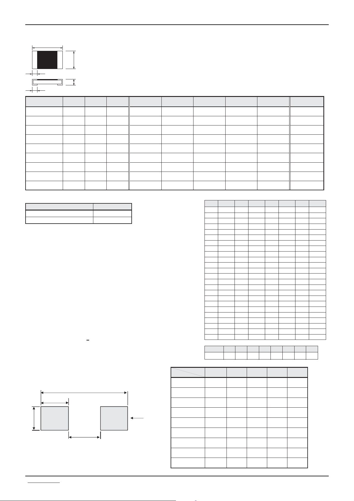
Chip Resistor Dimensions and Markings
<Marking method>
There are three or four digits used for the calculation number
according to IEC code and “R”is used for the decimal point.
a
b
Jumper type
MCR004 / 006 / 01 / 25 / 50 / 100
MCR03 / 10 / 18
Marking method of MCR03
The description of markings on the chip resistor are as shown below.
①
The nominal resistance is expressed in by E-24series 3 digits.
The first 2 digits apply to the resistance value and the last one indicates
the number of zeros to follow. The R is used as a decimal point.
Example:100k= 104
②
・
For the resistance value contained in E96 series.
The nominal resistance is expressed in 3 digits. The first 2 digits is
symbol to the resistance value and the last one is symbol to multipliers.
Example : 100k= 01d (01d100×10
Example : 3.01k= 47b
・
For the resistance value not contained in E96 series and contained
in E-24 series.
The marking is expressed by E-24 series in 3 digits and one short bar
under the last marking letter.
Example : 390= 391
C
L
103
W
t
Part No. Type Code (mm) (inch) L W t a b
MCR004
MCR006
MCR01
MCR03
MCR10
MCR18
MCR25
MCR50
MCR100
YZP,RZP 0402 01005
YRT 0603 0201
MRT 1005 0402
ERT 1608 0603
ERT 2012 0805
ERT 3216 1206
JZH 3225 1210
JZH 5025 2010
JZH 6432 2512
arking method of jumper type
Marking method (J class):
Marking method (F/D class):
Land pattern Example
B
D
A
Marking existenc
No
Yes
(47b301×101 = 3010= 3.01k)
0.4±0.02 0.2±0.02 0.13±0.02 0.1±0.03 0.1±0.03
0.6±0.03 0.3±0.03 0.23±0.03 0.15±0.05 0.15±0.05
1.0±0.05 0.5±0.05 0.35±0.05 0.2±0.1
1.6±0.1 0.8±0.1 0.45±0.1 0.3±0.2 0.3±0.2
2.0±0.1 1.25±0.1 0.5±0.1 0.35±0.2 0.35±0.2
3.05±0.15 1.55±0.15 0.55±0.1 0.45±0.25 0.35±0.25
3.2±0.15 2.5±0.15 0.55±0.15 0.5±0.25 0.5±0.25
5.0±0.15 2.5±0.15 0.55±0.15 0.6±0.25 0.6±0.25
6.3±0.15 3.2±0.15 0.55±0.15 0.6±0.25 0.6±0.25
3
= 100,000= 100k)
Part No.
MCR004
MCR006
MCR01
MCR03
Dimensions
ymbol for E96 Series nominal resistance value
Symbol E96 Symbol E96 Symbol E96 Symbol E96
25
100
01
102
02
105
03
107
04
110
05
113
06
115
07
118
08
121
09
124
10
127
11
130
12
133
13
137
14
140
15
143
16
147
17
150
18
154
19
158
20
162
21
165
22
169
23
174
24
ymbol for multipliers
Symbol A b C d E F X Y
multipliers 10
010110210310410510−110−2
Type Code A
YZP,RZP 0.2
YRT
MRT
ERT
0.3
0.5
0.5
178
26
182
27
187
28
191
29
196
30
200
31
205
32
210
33
215
34
221
35
226
36
232
37
237
38
243
39
249
40
255
41
261
42
267
43
274
44
280
45
287
46
294
47
301
48
309
B
0.4
0.84
1.3
1.3
Land
MCR10
MCR18
MCR25
MCR50
MCR100
ERT
ERT
JZH
JZH
JZH
1.2
2.2
2.2
3.8
5.1
2.6
4.0
4.0
6.0
8.1
(Unit : mm)
+0.05
0.25
−0.1
49
50
51
52
53
54
55
56
57
58
59
60
61
62
63
64
65
66
67
68
69
70
71
72
0.16
1.15
0.3
0.5
0.5
1.5
2.3
2.3
3.0
Data Sheet MCR series < General Purpose >
Marking
existence
No
No
No
Yes ∗
Yes
Yes
Yes
Yes
Yes
73
316
74
324
75
332
76
340
77
348
78
357
79
365
80
374
81
383
82
392
83
402
84
412
85
422
86
432
87
442
88
453
89
464
90
475
91
487
92
499
93
511
94
523
95
536
96
549
C
D
0.1
0.27
0.4
0.4
0.7
0.9
0.9
1.1
1.5
562
576
590
604
619
634
649
665
681
698
715
732
750
768
787
806
825
845
866
887
909
931
953
976
www.rohm.com
3/6
c
○
2012 ROHM Co., Ltd. All rights reserved.
2012.03 - Rev.
Page 4

A
8
8
Derating Curve
When the ambient temperature exceeds 70°C, power dissipation must be adjusted according to the derating curves below.
MCR004 / 006 / 100
100
80
60
40
20
PERCENT RATED POWER (%)
0
−55 0 70 100 125
AMBIENT TEMPERATURE (°C)
Characteristics
Test Items Test Conditions
Guaranteed Value
Resistor Type
MCR01 / 03 / 10 / 18 / 25 / 50
100
80
60
40
20
PERCENT RATED POWER (%)
0
Jumper Type
−55 0 70 100 155
AMBIENT TEMPERATURE (°C)
Data Sheet MCR series < General Purpose >
Resistance
Variation of resistance
with temperature
Overload
Solderability
Resistance to
soldering heat
Rapid change of
temperature
Damp heat, steady state
Endurance at 70°C
Endurance
See P.1
See P.1
± (2.0%+0.1Ω) Max. 50mΩ
A new uniform coating of minimum of
95% of the surface being immersed
and no soldering damage.
± (1.0%+0.05Ω)
Max. 50mΩ
No remarkable abnormality on the appearance.
± (1.0%+0.05Ω)
± (3.0%+0.1Ω)
± (3.0%+0.1Ω)
± (3.0%+0.1Ω)
Max. 50mΩ
Max. 100mΩ
Max. 100mΩ
Max. 100mΩ
°C
20
Measurement : +20 / −55 / +20 / +125°C
Rated voltage (current) ×2.5, 2s.
Limiting element voltage ×2 : (See P.1)
Rosin·Ethanol (25%WT)
Soldering condition : 235±5
°C
Duration of immersion : 2.0±0.5s
Soldering condition : 260±5
°C
Duration of immersion : 10±1s
Test temp.
−55
°C
to +125°C 100cyc (MCR004 / 006)
°C
to +125°C 300cyc (MCR01)
−55
°C
to +125°C 5cyc (MCR03 / 10 / 18 / 25 / 50 / 100)
−55
40°C, 93%RH
Test time : 1,000h to 1,048h
70°C
Rated voltage (current)
1.5h : ON − 0.5h : OFF
Test time : 1,000h to 1,048h
125°C (MCR004 / 006 / 25 / 50 / 100)
155°C (MCR01 / 03 / 10 / 18)
Test time : 1,000h to 1,048h
23±5
°C
Resistance to solvent
Bend strength of
the end face plating
± (1.0%+0.05Ω)
± (1.0%+0.05Ω)
Max. 50mΩ
Max. 50mΩ
Without mechanical damage such as breaks.
, Immersion cleaning, 5±0.5min
Solvent : 2−propanol
−
Compliance Standard(s) : IEC60115−
JISC 5201−
Technical data
Parameter Unit
Insulation
resistance
Failure rate
Weight
mg/pc
MCR004
YZP / RZP
MΩ−
Fit
0.0038
0.04
MCR006
YRT
1000 1000 1000 1000
0.0185
0.150
MCR01
MRT
0.0185
0.565
MCR03
ERT
0.0185
2.03
MCR10
ERT
0.0185
4.73
MCR18
ERT
1000
0.0185
8.56
MCR25
JZH
1000
0.0203
16.5
MCR50
JZH
1000
0.0201
25.8
MCR100
JZH
1000
0.0586
42.0
www.rohm.com
4/6
c
○
2012 ROHM Co., Ltd. All rights reserved.
2012.03 - Rev.
Page 5

A
W
T
)
)
Tape Dimensions
Paper Tape
P
0
P
2
P
Data Sheet MCR series < General Purpose >
(Unit : mm
WType CodePart No. F E A
1
φD
0
E
F
B
0
W
8.0±0.2MCR004 YZP 3.5±0.05 1.75±0.1
8.0±0.2MCR006 YRT 3.5±0.05 1.75±0.1
8.0±0.3MCR01 MRT 3.5±0.05 1.75±0.1
0
B
0
0.24±0.03 0.45±0.03
0.38±0.03 0.68±0.03
0.7±0.1 1.2±0.1
Top tape
Base paper
Embossed Tape
(Bottom tape)
<MCR004>
A
0
B
0
Components Cavity
P
0
P
2
A
0
8.0±0.3MCR03 ERT 3.5±0.05 1.75±0.1
1.0±0.1 1.8±0.1
8.0±0.3MCR10 ERT 3.5±0.05 1.75±0.1
2
T
Type CodePart No. P
MCR004 YZP
MCR006 YRT
MCR01 MRT
MCR03 ERT
MCR10 ERT
MCR18 ERT
8.0±0.3MCR18 ERT 3.5±0.05 1.75±0.1
D
φ1.5
φ1.5
φ1.5
φ1.5
φ1.5
φ1.5
0
+0.1
0
+0.1
0
+0.1
0
+0.1
0
+0.1
0
+0.1
0
0
4.0±0.1
4.0±0.1
4.0±0.1
4.0±0.1
4.0±0.1
4.0±0.1
P
2.0±0.05
2.0±0.05
2.0±0.1
4.0±0.1
4.0±0.1
4.0±0.1
1.55±0.1 2.3±0.1
1.9±0.2 3.5±0.2
1
2.0±0.05 Max 0.5
2.0±0.05 Max 0.5
2.0±0.05
2.0±0.05
2.0±0.05
2.0±0.05
P
2
T
2
Max 1.1
Max 1.1
Max 1.1
Max 1.1
(Unit : mm
WType CodePart No. F E A
4.0±0.05MCR004 RZP 1.8±0.02 0.9±0.05
0
φD
E
F
W
8.0±0.3MCR25 JZH 3.5±0.05 1.75±0.1
12±0.3MCR50 JZH 5.5±0.05 1.75±0.1
0
B
0
0.23±0.02 0.43±0.02
3.0±0.1 3.5±0.1
3.4±0.2 5.6±0.2
P
Top tape
Base Embossed
<MCR25 / 50 / 100>
F
0
B
A
P
0
0
1
Components
P
2
P
1
Pocket
Type CodePart No. P
T
2
MCR004 RZP
MCR25 JZH
MCR50 JZH
0
φD
E
MCR100 JZH
2
12±0.3MCR100 JZH 5.5±0.05 1.75±0.1
D
φ0.8
φ1.5
φ1.5
φ1.5
0
±0.04
+0.1
0
+0.1
0
+0.1
0
0
2.0±0.04
4.0±0.1
4.0±0.1
4.0±0.1
P
1.0±0.02
4.0±0.1
4.0±0.1
4.0±0.1
3.5±0.2 6.7±0.2
1
1.0±0.02 0.2±0.02
2.0±0.05 Max 1.1
2.0±0.05
2.0±0.05
P
2
T
2
Max 1.1
Max 1.1
www.rohm.com
5/6
c
○
2012 ROHM Co., Ltd. All rights reserved.
2012.03 - Rev.
Page 6

A
Reel Dimensions
ABD
Data Sheet MCR series < General Purpose >
0 2
0 4
0 6
0 2
0 4
0 6
0 8
0 8
MCR004
MCR006
MCR01
MCR03
MCR10
MCR18
MCR25
MCR50
MCR100
C
YZP
YRT
MRT
ERT
ERT
ERT
JZH
JZH
JZH
Label
ACCORDING TO EIAJ ET-7200B
AType CodePart No. B C D
+1.0
9
13
0
+1.0
0
φ180
0
−1.5
φ60
+1.0
0
(Unit : mm)
φ13±0.2
ABD
C
Label
ACCORDING TO EIAJ RRM-048c
(Unit : mm)
AType CodePart No. B C D
+1.0
5
−0.6
www.rohm.com
6/6
c
○
2012 ROHM Co., Ltd. All rights reserved.
φ13±0.2φ178±1.0MCR004 RZP φ60±1.0
2012.03 - Rev.
Page 7

Notes
No copying or reproduction of this document, in par t or in whole, is permitted without the
consent of ROHM Co.,Ltd.
The content specied herein is subject to change for improvement without notice.
The content specied herein is for the purpose of introducing ROHM's products (hereinafter
"Products"). If you wish to use any such Product, please be sure to refer to the specications,
which can be obtained from ROHM upon request.
Examples of application circuits, circuit constants and any other information contained herein
illustrate the standard usage and operations of the Products. The peripheral conditions must
be taken into account when designing circuits for mass production.
Great care was taken in ensuring the accuracy of the information specied in this document.
However, should you incur any damage arising from any inaccuracy or misprint of such
information, ROHM shall bear no responsibility for such damage.
The technical information specied herein is intended only to show the typical functions of and
examples of application circuits for the Products. ROHM does not grant you, explicitly or
implicitly, any license to use or exercise intellectual property or other rights held by ROHM and
other parties. ROHM shall bear no responsibility whatsoever for any dispute arising from the
use of such technical information.
The Products specied in this document are intended to be used with general-use electronic
equipment or devices (such as audio visual equipment, ofce-automation equipment, communication devices, electronic appliances and amusement devices).
The Products specied in this document are not designed to be radiation tolerant.
While ROHM always makes effor ts to enhance the quality and reliability of its Products, a
Product may fail or malfunction for a variety of reasons.
Please be sure to implement in your equipment using the Products safety measures to guard
against the possibility of physical injury, re or any other damage caused in the event of the
failure of any Product, such as derating, redundancy, re control and fail-safe designs. ROHM
shall bear no responsibility whatsoever for your use of any Product outside of the prescribed
scope or not in accordance with the instruction manual.
The Products are not designed or manufactured to be used with any equipment, device or
system which requires an extremely high level of reliability the failure or malfunction of which
may result in a direct threat to human life or create a risk of human injur y (such as a medical
instrument, transportation equipment, aerospace machiner y, nuclear-reactor controller, fuelcontroller or other safety device). ROHM shall bear no responsibility in any way for use of any
of the Products for the above special purposes. If a Product is intended to be used for any
such special purpose, please contact a ROHM sales representative before purchasing.
If you intend to export or ship overseas any Product or technology specied herein that may
be controlled under the Foreign Exchange and the Foreign Trade Law, you will be required to
obtain a license or permit under the Law.
Notice
www.rohm.com
© 2012 ROHM Co., Ltd. All rights reserved.
Thank you for your accessing to ROHM product informations.
More detail product informations and catalogs are available, please contact us.
ROHM Customer Support System
http://www.rohm.com/contact/
R1120A
 Loading...