

Page 1
High Power Chip Resistors
<Wide Terminal type>
LTR18 (3216 size : 1 / 2W)
Features
1) mproved welding strength
The structure of longer electrodes provides the wider welding area than the chip resistors with normal electrodes, and this
enhanced the solder welding strength.
2) Increased surge-resistance
This is achieved by Rohm’s original trimming technology plus resistive element patterning.
3) High-power tolerance
Two times of the rated power is guaranteed than the normal-electrode resistors.
ROHM resistors are ISO-9001 & ISO/TS16949 certified.
Applications
Automotive, industrial and power supply.
Ratings
Design and specifications are subject to change without notice.
Carefully check the specification sheet before using or ordering it.
Item Conditions Specifications
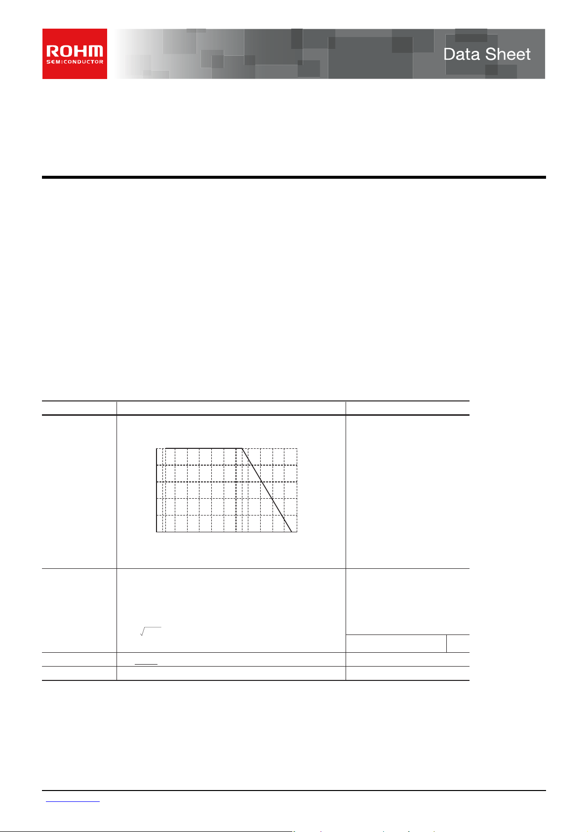
Rated power
Power must be derated according to the power derating curve in
Figure 1 when ambient temperature exceeds 70°
100
80
60
40
POWER LOAD (%)
20
0
−55 0 70 100 155
AMBIENT TEMPERATURE (°C)
Fig.1
C
.
0.5W (1 / 2W)
at 70°C
Rated voltage
Nominal resistance
Operating temperature
www.rohm.com
1/3
c
○
2010 ROHM Co., Ltd. All rights reserved.
The voltage rating is calculated by the following equation.
If the value obtained exceeds the limiting element voltage,
the voltage rating is equal to the maximum operating voltage.
E: Rated voltage (V)
E= P×R
See Table 1.
D(±0.5%) F(±1%) J(±5%)
P: Rated power (W)
R: Nominal resistance (Ω)
Limiting element voltage 200V
C to + 155°C
−55°
2010.06 - Rev.E
Page 2
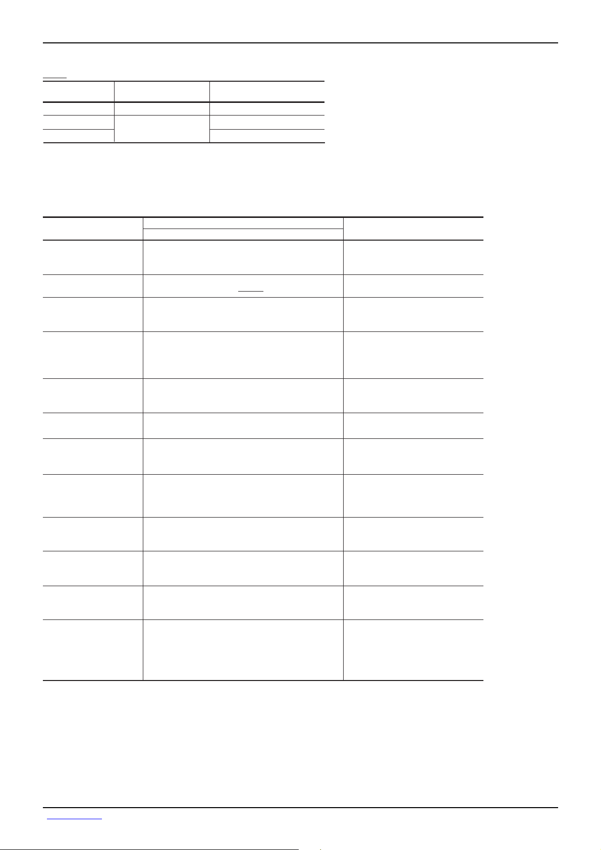
Table 1
R
t
n.
Data Sheet LTR18
esistance tolerance
D (±0.5%)
F (±1%)
J (±5%)
Resistance range
(Ω)
10 to 1M (E24)
1 to 1M (E24)
Resistance temperature coefficien
(ppm/°C)
±100
±100
±200
Before using components in circuits where they will be exposed to transients such as pulse loads (short–duration, high– level
loads), be certain to evaluate the component in the mounted state. In addition, the reliability and performance of this
component cannot be guaranteed if it is used with a steady state voltage that is greater than its rated voltage.
Characteristics
Resistance
Variation of resistance
with temperature
Overload
Solderability
Resistance to
soldering heat
Rapid change of
temperature
Damp heat, steady state
Endurance at 70°C
Endurance
Resistance to solvent
Bend strength of
the end face plating
Item Test conditions (JIS C 5201-1)
A new uniform coating of minimum of
95% of the surface being immersed
and no soldering damage.
No remarkable abnormality on the appearance.
Without mechanical damage such as breaks.
Guaranteed value
Resistor type
J : ±5%
F : ±1%
D : ±0.5%
See Table.1
± (2.0%+0.1Ω)
± (1.0%+0.05Ω)
± (1.0%+0.05Ω)
± (3.0%+0.1Ω)
± (3.0%+0.1Ω)
± (3.0%+0.1Ω)
± (1.0%+0.05Ω)
± (1.0%+0.05Ω)
JIS C 5201-1 4.5
JIS C 5201-1 4.8
Measurement : −55 / +25 / +125°C
JIS C 5201-1 4.13
Rated voltage (current) ×2.5, 2s.
Maximum overload voltage : 200V
JIS C 5201-1 4.17
Rosin·Ethanol (25%WT)
Soldering condition : 235±5
Duration of immersion : 2.0±0.5s.
JIS C 5201-1 4.18
Soldering condition : 260±5
Duration of immersion : 10±1s.
JIS C 5201-1 4.19
Test temp. : −55
JIS C 5201-1 4.24
°C, 93%RH
40
Test time : 1,000h to 1,048h
JIS C 5201-1 4.25.1
Rated voltage (current), 70
1.5h : ON − 0.5h : OFF
Test time : 1,000h to 1,048h
JIS C 5201-1 4.25.3
°C
155
Test time : 1,000h to 1,048h
JIS C 5201-1 4.29
23±5
°C
, Immersion cleaning, 5±0.5mi
Solvent : 2-propanol
JIS C 5201-1 4.33
°C
to +125°C 5cyc
°C
°C
°C
EIAJ ED-4701/300 Test method 304
Voltage : 3kv
Static electric
characteristics
± (5.0%+0.05Ω)
C : 100pF
R : 1.5kΩ
Apply cycle : 1 time
www.rohm.com
2/3
c
○
2010 ROHM Co., Ltd. All rights reserved.
2010.06 - Rev.E
Page 3

R
P
Dimensions (Unit : mm)
Data Sheet LTR18
0.5±0.2
0.55±0.1
1.6±0.15
3.2±0.15
1.6±0.15
0.3±0.2
Packaging
Reel Taping
ABD
0 2
0 4
0 6
0 8
C
ABCD
φ180
0
−1.5
φ60
+1
0
+1.0
9
0
Label
EIAJ ET-7200B compliant
(Unit: mm)
φ13±0.2
0 2
0 4
0 6
0 8
Part designation
No.
Resistive element
1
(Oxide metal thick film)
2
Silver thick film electrode
3
Nickel electrode
4
Sn electrode
5
Alumina substrate
6
Overcoating (Resin)
Heat crimp cover/Tape
Thick paper
(Underside paper tape) Chip resistor Square punchout hole
mount
WFEA0 B0
8.0±0.3 3.5±0.05 1.75±0.1
D0 P0 P1 P2 T2
+0.1
φ1.5
0
Material
P0
P2 P1
A0
4.0±0.1 4.0±0.1 2.0±0.05 Max. 1.1
φD0
B0
1.65
+0.2
−0.1
F
(Unit: mm)
+0.2
2.4
−0.1
E
W
T
2
TLR18
Part No.
E Z P J
Resistance tolerance
J
Nominal resistance
±
0.5%D
±
1%F
±
5%
Resistance code, 3 or 4 digits.
Resistance
tolerance
F , DJ::4 digits
Resistance
code
3 digits
ackaging Specifications Code
Part No.
eel (φ180mm) : Compatible with JEITA standard "EIAJ ET-7200B"
: Standard product
Code Packaging specifications Reel
EZP Paper tape (4mm Pitch) φ180mm (7inch)LTR18
Resistance tolerance
D(±0.5%) F(±1%) J(±5%)
Basic ordering unit
(pcs)
5,000
www.rohm.com
3/3
c
○
2010 ROHM Co., Ltd. All rights reserved.
2010.06 - Rev.E
 Loading...