

KD2003-DC10A
Printheads
Thick film thermal printhead
(8 dots / mm)
KD2003-DC10A
The KD2003-DC10A is a 24 V standa rd thick film the rmal printhead w ith a printing speed up to 6 inches / s that has been
developed mainly for label printer use .
zApplications
High speed label printer
High speed bar code printer
High speed ticket printer
Various high speed terminal printers
zFeatures
1) Newly developed thick-film fast response thermal element is empl oyed for th is series an d 6 inches / s o r 150 mm / s i s
possible without thermal history contro l. It is possible to print 10 inches / s or 250 mm / s if external thermal history
control is used.
2) 150km life realized by attributing durable new protection film .
3) New partial glaze construction makes it compatible with the thermal transfer application.
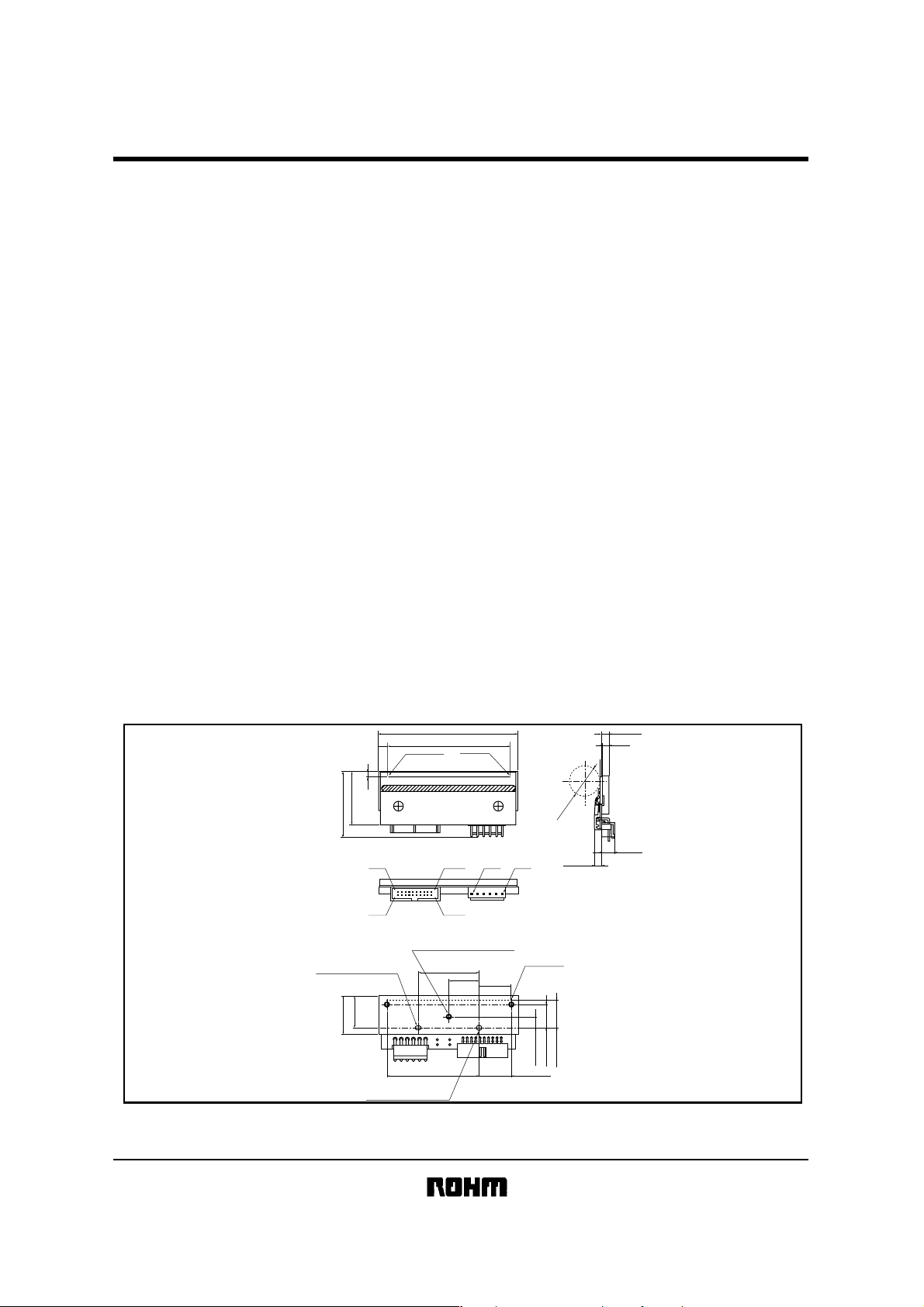
zExternal dimensions (Unit : mm)
DOT #640
91
DOT #1
80 (EFFECTIVE PRINT WIDTH)
6.1±0.4
(5)
(3)
Max.36
Max.45
#2
#1
CONNECTOR A CONNECTOR B
φ3H10 LENGTH 4
(EFFECTIVE DEPTH 3)
25±0.5
(20.8)
φ3H10
(EFFECTIVE DEPTH 3)
#20
#6 #1
#19
3-M3 (EFFECTIVE DEPTH 3)
40±0.3
20±0.3
20±0.2
60.5±0.3
DOT #640
7.3±0.3
20.5±0.3
Max.φ20
Max.5.5
15.3±0.3
17.8±0.2
Max.10
1/3
Printheads
zEquivalent circuit
VH
KD2003-DC10A
DOT #640 DOT #1
VSF
GND
DD
V
STB2
STB1
N.C.
/LAT
CLK
DI4
DO4
DI3
DO3
DI2
DO2
DI1
DO1
TM
TM
CONNECTOR
VSF : Usually VSF and VH are connected.
When measuring R value of Heatelement , VSF and VH should be
separated.
L/S
#640 #321 #320
SHIFT
REGISTER
DI No.
DI1
DI2
DI3
DI4
LATCH REGISTER
SHIFT
REGISTER
THERMISTOR
30kΩ B: 3950K
DOT No.
1 to 192
193 to 320
321 to 512
513 to 640
SHIFT
REGISTER
#1
SHIFT
REGISTER
STB No.
DOT No.
STB1 1 to
321 to
320
640STB2
zPin assignments
CircuitNo. No. Circuit
1 GND
2
3
4
5
6
7
8
9
10
VSF
GND
V
DD
STB2
CLK
DI4
DO4
N.C.
LAT
11
12
13
14
15
16
17
18
19
20
TM
TM
DI3
DO3
DI2
DO2
N.C.
STB1
DI1
DO1
Fig. 1
CONNECTOR BCONNECTOR A
No.
Circuit
1VH
2
3
4
5
6
VH
VH
GND
GND
GND
2/3
Printheads
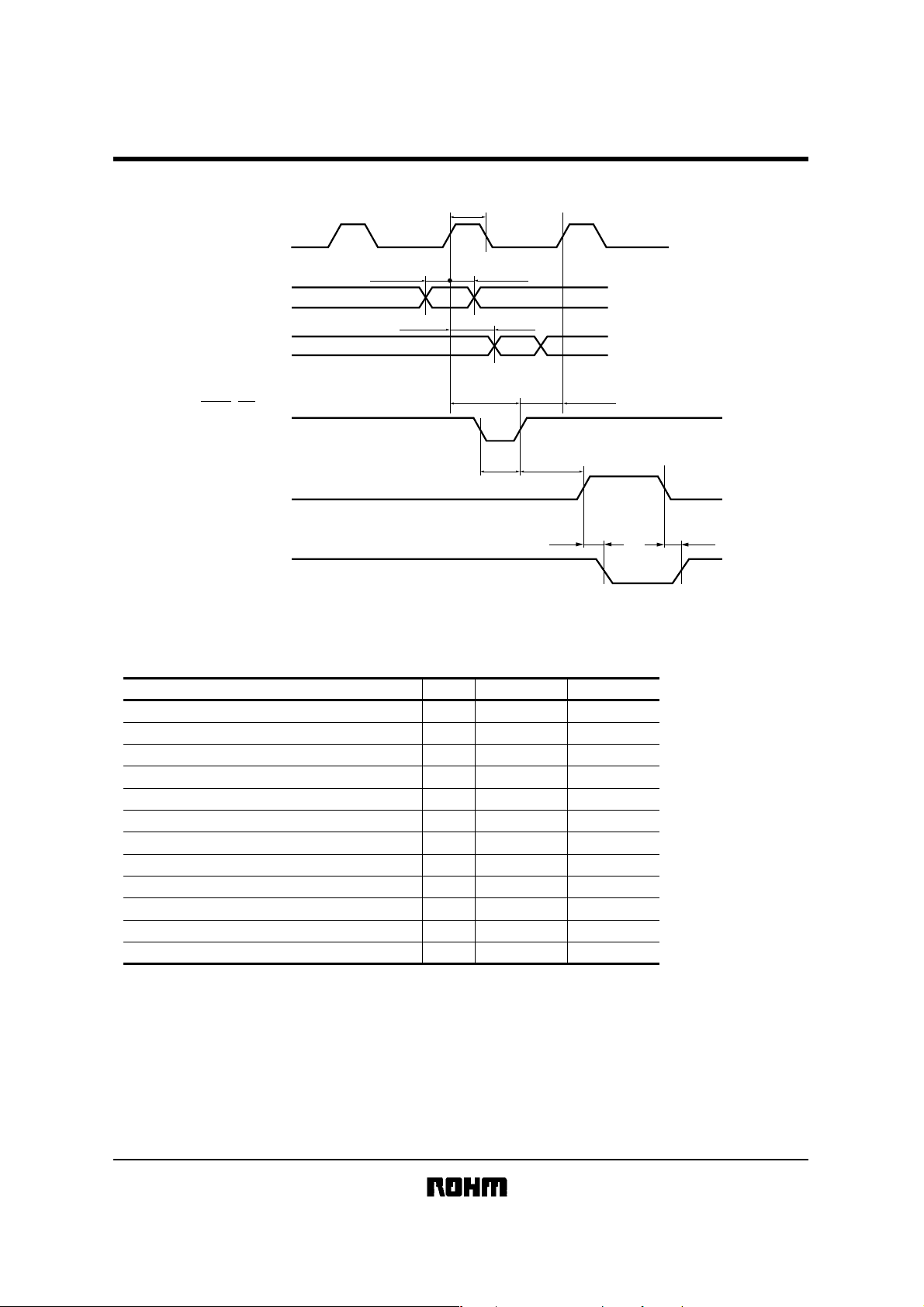
zTiming chart
CLOCK(CLK)
DATA IN(DI)
High: BLACK
Low: WHITE
DATA OUT(DO)
High: BLACK
Low: WHITE
KD2003-DC10A
tw CLK
t setup DI t hold DI
td DO
LATCH(LAT)
High: HOLD
Low: THROUGH
STROBE(STB)
DRIVER OUT
zCharacteristics
Parameter
Effective printing width
Dot pitch
Total dot number
Average resistance value
Applied voltage
Applied power
Print cycle
Maximum number of dots energized simultaneously
Maximum clock frequency
Maximum roller diameter
Running life / pulse life
Operating temperature
t setup LAT
tw LAT
Fig.2
t hold LAT
t setup STB
tdo tdo
Symbol Typical Unit
−
−
−
Rave
V
H
P
O
SLT
−
−
−
−
−
80
0.125
640
650
24
0.80
0.82
640
12
φ
20.0
150 / (1×10
5 to 45
8
)
mm
mm
dots
Ω
V
W / dot
ms
dots
MHz
mm
km / pulses
°C
3/3

Appendix
No technical content pages of this document may be reproduced in any form or transmitted by any
means without prior permission of ROHM CO.,LTD.
The contents described herein are subject to change without notice. The specifications for the
product described in this document are for reference only. Upon actual use, therefore, please request
that specifications to be separately delivered.
Application circuit diagrams and circuit constants contained herein are shown as examples of standard
use and operation. Please pay careful attention to the peripheral conditions when designing circuits
and deciding upon circuit constants in the set.
Any data, including, but not limited to application circuit diagrams information, described herein
are intended only as illustrations of such devices and not as the specifications for such devices. ROHM
CO.,LTD. disclaims any warranty that any use of such devices shall be free from infringement of any
third party's intellectual property rights or other proprietary rights, and further, assumes no liability of
whatsoever nature in the event of any such infringement, or arising from or connected with or related
to the use of such devices.
Upon the sale of any such devices, other than for buyer's right to use such devices itself, resell or
otherwise dispose of the same, no express or implied right or license to practice or commercially
exploit any intellectual property rights or other proprietary rights owned or controlled by
ROHM CO., LTD. is granted to any such buyer.
Products listed in this document are no antiradiation design.
Notes
The products listed in this document are designed to be used with ordinary electronic equipment or devices
(such as audio visual equipment, office-automation equipment, communications devices, electrical
appliances and electronic toys).
Should you intend to use these products with equipment or devices which require an extremely high level of
reliability and the malfunction of with would directly endanger human life (such as medical instruments,
transportation equipment, aerospace machinery, nuclear-reactor controllers, fuel controllers and other
safety devices), please be sure to consult with our sales representative in advance.
About Export Control Order in Japan
Products described herein are the objects of controlled goods in Annex 1 (Item 16) of Export Trade Control
Order in Japan.
In case of export from Japan, please confirm if it applies to "objective" criteria or an "informed" (by MITI clause)
on the basis of "catch all controls for Non-Proliferation of Weapons of Mass Destruction.
Appendix1-Rev1.1
 Loading...