

ROHM EMH1, UMH1N, IMH1A Technical data
Datasheet
www.rohm.com
© 2012 ROHM Co., Ltd. All rights reserved.
EMH1 / UMH1N / IMH1A
NPN 100mA 50V Complex Digital Transistors (Bias Resistor Built-in Transistors)
l
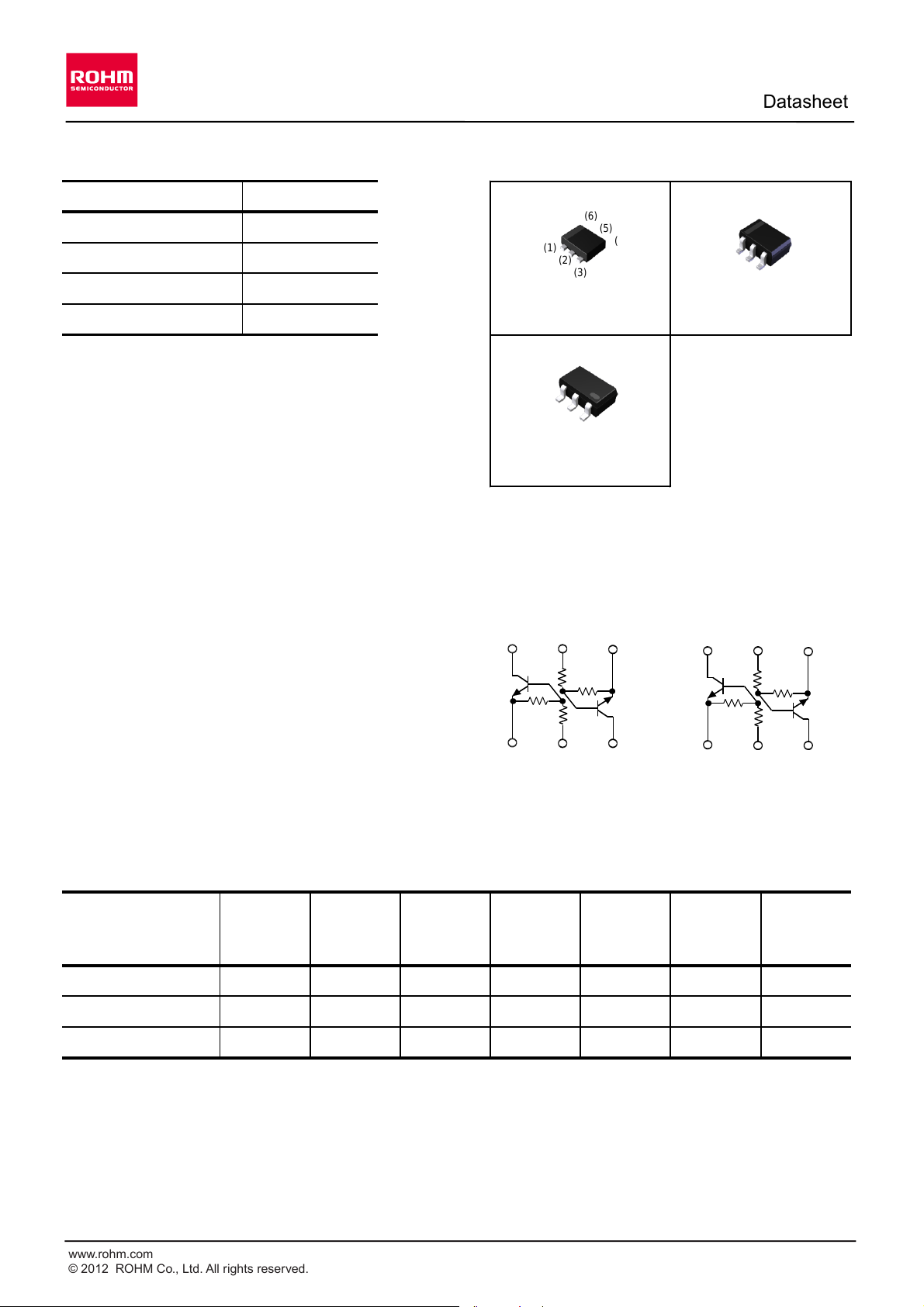
Outline
l
Features
1) Built-In Biasing Resistors, R1 = R2 = 22kW.
2) Two DTC124E chips in one package.
3) Built-in bias resistors enable the configuration of
an inverter circuit without connecting external
input resistors (see inner circuit).
4) The bias resistors consist of thin-film resistors
with complete isolation to allow negative biasing
l
Inner circuit
of the input. They also have the advantage of
completely eliminating parasitic effects.
5) Only the on/off conditions need to be set for
operation, making the circuit design easy.
6) Lead Free/RoHS Compliant.
l
Application
Inverter circuit, Interface circuit, Driver circuit
l
Packaging specifications
R
1
22kW
R
2
22kW
Parameter
Tr1 and Tr2
V
CC
50V
I
C(MAX.)
100mA
Part No.
Package
Package
size
(mm)
Taping
code
8,000H18
Tape width
(mm)
Basic
ordering
unit (pcs)
Marking
Reel size
(mm)
EMH1
EMT6
1616
T2R
180
3,000
H1
IMH1A
3,000
H1
UMH1N
UMT6
2021
TR
180
8
SMT6
2928
T108
180
8
EMT6
UMT6
SMT6
EMH1
(SC-107C)
IMH1A
SOT-457 (SC-74)
UMH1N
SOT-353 (SC-88)
OUT
(6)
(2)
IN
(1)
GND
(3)
OUT
IN
(5)
GND
(4)
OUT
(4)
(2)
IN
(3)
GND
(1)
OUT
IN
(5)
GND
(6)
EMH1 / UMH1N
IMH1A
(6)
(5)
(4)
(1)
(2)
(3)
(4)
(5)
(6)
(3)
(2)
(1)
(6)
(5)
(4)
(1)
(2)
(3)
1/7
2012.06 - Rev.B
www.rohm.com
© 2012 ROHM Co., Ltd. All rights reserved.
Data Sheet
EMH1 / UMH1N / IMH1A
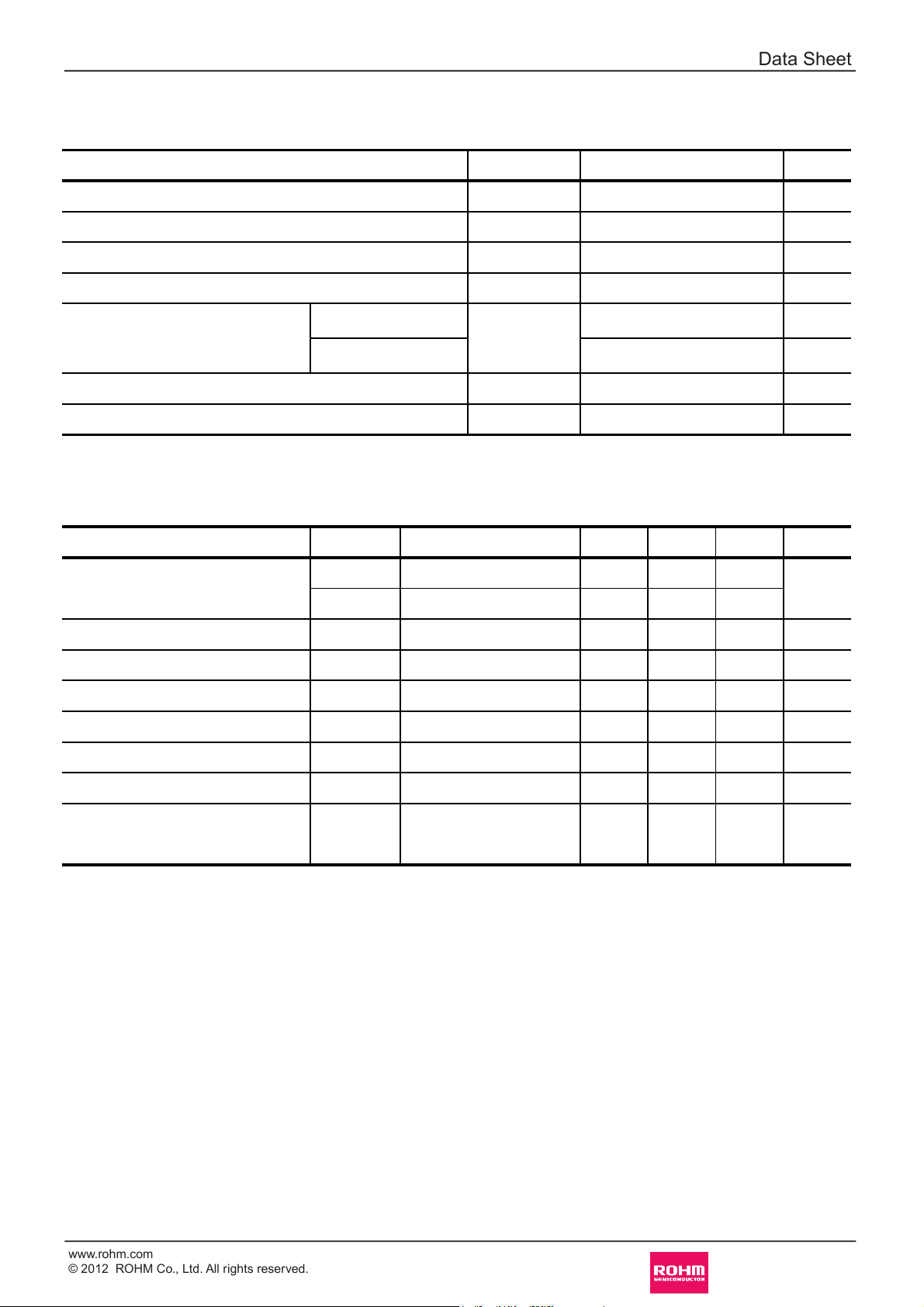
lAbsolute maximum ratings (Ta = 25°C)
<For Tr1 and Tr2 in common>
Supply voltage
Input voltage
Output current
Collector current
Power dissipation
Junction temperature
Range of storage temperature
lElectrical characteristics(Ta = 25°C)
<For Tr1 and Tr2 in common>
*1 Characteristics of built-in transistor
*2 Each terminal mounted on a reference footprint
*3 120mW per element must not be exceeded.
*4 200mW per element must not be exceeded.
Parameter
Symbol
Values
Unit
V
CC
50
V
V
IN
-10 to +40
V
I
O
30
mA
I
C(MAX.)
*1
100
mA
EMH1 / UMH1N
P
D
*2
150 (Total)
*3
mW
IMH1A
300 (Total)
*4
mW
T
j
150
°C
T
stg
-55 to +150
°C
Parameter
Symbol
Conditions
Unit
Min.
Typ.
Max.
Input voltage
V
I(off)
V
CC
= 5V, IO = 100mA
-
-
V
V
I(on)
VO = 0.2V, IO = 5mA
3.0--
0.5
V
Input current
I
I
VI = 5V
--0.36
mA
Output voltage
V
O(on)
IO / II = 10mA / 0.5mA
-
0.1
0.3
mA
DC current gain
G
I
VO = 5V, IO = 5mA
56--
-
Output current
I
O(off)
V
CC
= 50V, VI = 0V
--0.5
kW
Resistance ratio
R2/R
1
-
0.811.2
-
Input resistance
R
1
-
15.4
22
28.6
MHz
Transition frequency
fT
*1
V
CE
= 10V, IE = -5mA,
f = 100MHz
-
250
-
2/7
2012.06 - Rev.B
www.rohm.com
© 2012 ROHM Co., Ltd. All rights reserved.
Data Sheet
EMH1 / UMH1N / IMH1A
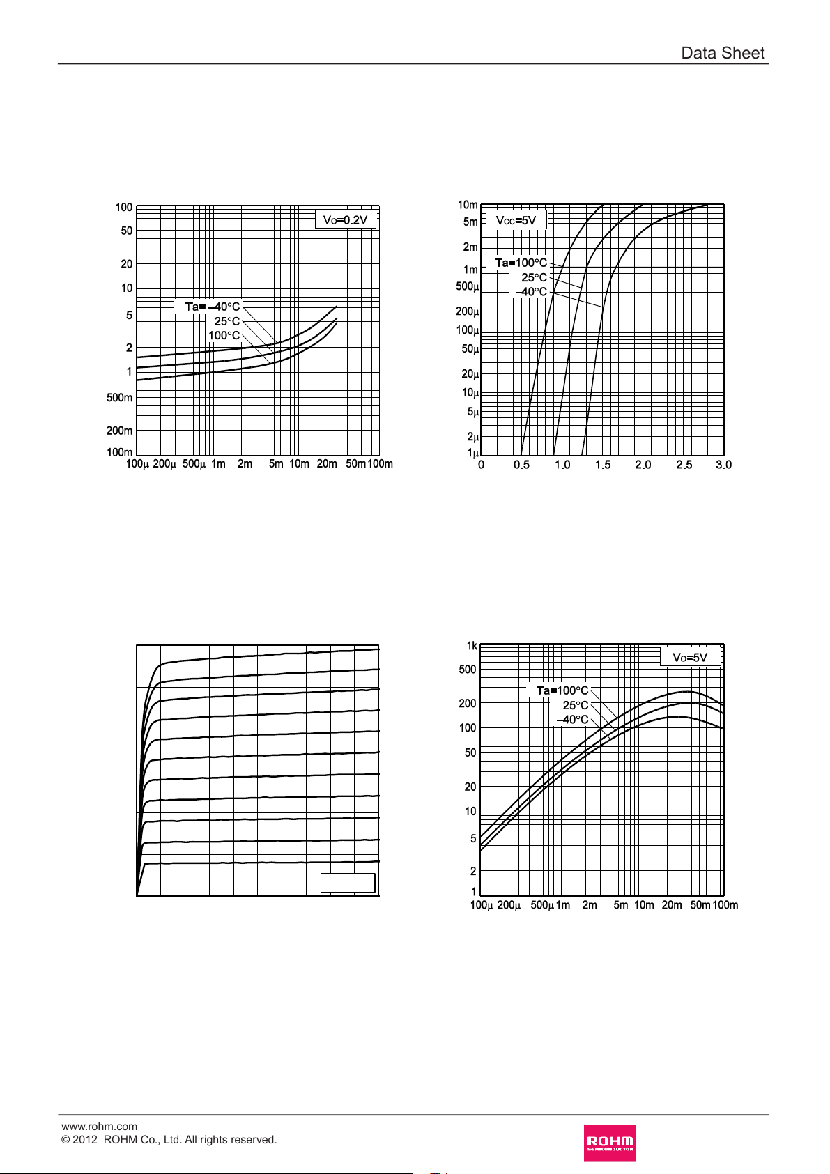
lElectrical characteristic curves(Ta = 25°C)
Fig.1 Input voltage vs. output current
(ON characteristics)
INPUT VOLTAGE : V
I(on)
[V]
OUTPUT CURRENT : IO [A]
Fig.2 Output current vs. input voltage
(OFF characteristics)
OUTPUT CURRENT : I
O
[A]
INPUT VOLTAGE : V
I(off)
[V]
Fig.3 Output current vs. output voltage
OUTPUT CURRENT : I
O
[mA]
OUTPUT VOLTAGE : VO [V]
Fig.4 DC current gain vs. output current
DC CURRENT GAIN : G
I
OUTPUT CURRENT : IO [A]
0
10
20
30
0 5 10
0A
70μA
80μA
100μA
110μA
120μA
130μA
90μA
II=
Ta=25ºC
60μA
50μA
140μA
150μA
3/7
2012.06 - Rev.B
 Loading...