

ESR25
Resistors
Anti-surge thick film chip resistor
ESR25 (1210 size : 1 / 2W)
zFeatu res
1) Power rating of 1 /2W (MCR25 1/4W)
2) Superior anti surge to MCR series
3) Highly reliable chip resistor
Ruthenium oxide dielectric offers superior resistance to the elements.
4) ROHM resistors have approved ISO–9001, ISO/TS 16949 certification.
Design and specifications are subject to change without notice. Carefully check the specification sheet before using or
ordering it.
5) This product is in compliance with the RoHS directive.
zApplications
Automotive, LCD Monitor, projector , power supply , charger, inverter and so on.
zRatings
Item Conditions Specifications
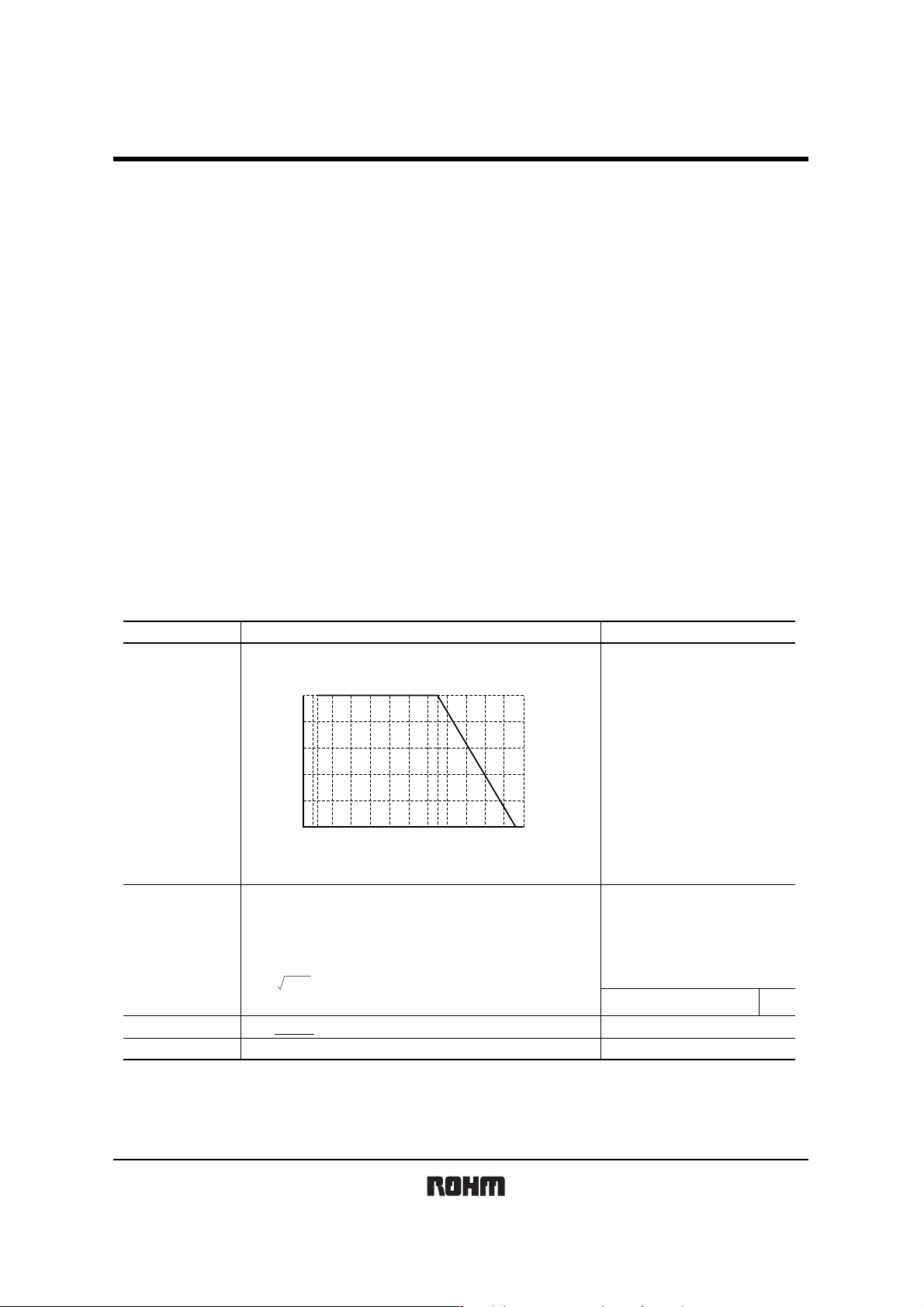
Rated power
Power must be derated according to the power derating curve in
Figure 1 when ambient temperature exceeds 70°
100
80
60
40
POWER LOAD (%)
20
0
−55 0 70 100 155
AMBIENT TEMPERATURE (°C)
Fig.1
C.
0.5W (1/2W)
at 70°C
Rated voltage
Nominal resistance
Operating temperature
The voltage rating is calculated by the following equation.
If the value obtained exceeds the limiting element voltage,
the voltage rating is equal to the maximum operating voltage.
E: Rated voltage (V)
E= P×R
See Table 1.
P: Rated power (W)
R: Nominal resistance (Ω)
Limiting element voltage 200V
C to +155°C
−55°
Rev.A 1/4
ESR25
Resistors
Table 1
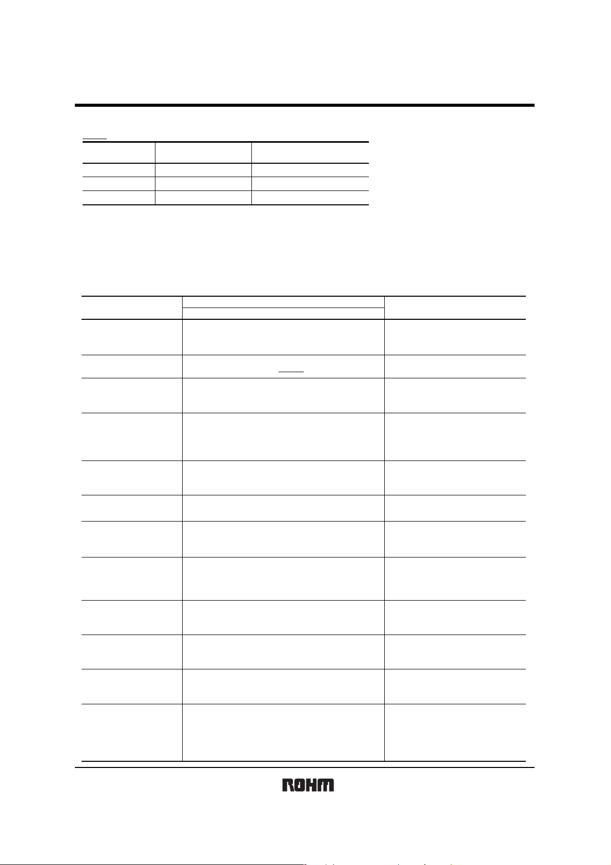
Resistance tolerance
D(±0.5%)
F (±1%)
J (±5%)
Resistance range
10 ≤ R ≤ 1M
(Ω)
(E24)
(E24)
(E24)
Resistance temperature coefficient
(ppm/°C)
±100
±1001 ≤ R ≤ 10M
±2001 ≤ R ≤ 10M
zBefore using components in circuits w here they will be exposed to transients such as pulse loads (short–duration, high– level l oads), be certain to evaluate the
component in the mounted state. In addition, the reliability and performance of this component cannot be guaranteed if it is used with a steady st ate voltage that
is greater than its rated voltage.
z
Characteristics
Resistance
Variation of resistance
with temperature
Overload
Item Test conditions (JIS C 5201-1)
Guaranteed value
Resistor type
J : ±5%
F : ±1%
D : ±0.5%
See Table.1
± (2.0%+0.1Ω)
JIS C 5201-1 4.5
JIS C 5201-1 4.8
Measurement : −55 / +25 / +125°C
JIS C 5201-1 4.13
Rated voltage (current) ×2.5, 2s.
Maximum overload voltage : 400V
JIS C 5201-1 4.17
Rosin·Ethanol (25%WT)
Soldering condition : 235±5
Duration of immersion : 2.0±0.5s.
JIS C 5201-1 4.18
Soldering condition : 260±5
Duration of immersion : 10±1s.
JIS C 5201-1 4.19
Test temp. : −55
JIS C 5201-1 4.24
°C, 93%RH
40
Test time : 1,000h to 1,048h
JIS C 5201-1 4.25.1
Rated voltage (current), 70
1.5h : ON − 0.5h : OFF
Test time : 1,000h to 1,048h
JIS C 5201-1 4.25.3
°C
155
Test time : 1,000h to 1,048h
JIS C 5201-1 4.29
23±5
°C
, Immersion cleaning, 5±0.5min.
Solvent : 2-propanol
JIS C 5201-1 4.33
EIAJ ED-4701 1300 Test method 304
Voltage : 3kv
R : 1.5kΩ
C : 100pF
Apply cycle : 1 time
°C to
°C
°C
+125°C 5cyc
°C
Solderability
Resistance to
soldering heat
Rapid change of
temperature
Damp heat, steady state
Endurance at 70°C
Endurance
Resistance to solvent
Bend strength of
the end face plating
Static electric
characteristics
A new uniform coating of minimum of
95% of the surface being immersed
and no soldering damage.
± (1.0%+0.05Ω)
No remarkable abnormality on the appearance.
± (1.0%+0.05Ω)
± (3.0%+0.1Ω)
± (3.0%+0.1Ω)
± (3.0%+0.1Ω)
± (1.0%+0.05Ω)
± (1.0%+0.05Ω)
Without mechanical damage such as breaks.
± (5.0%+0.05Ω)
Rev.A 2/4

Resistors
zDimensions (Unit : mm)
0.5±0.25
ESR25
1
2
0.5±0.25
3.2±0.15
3
4
5
0.55±0.1
No.
1
Resistive element (Oxide metal thick film)
2
Silver thick film electrode
Nickel electrode
3
Sn electrode
4
Alumina substrate
5
Overcoating (Resin)
6
2.5±0.15
6
z
Packaging
Reel Taping
ABD
0 2
0 4
0 6
0 2
0 4
0 6
0 8
0 8
Material
P
0
P
2
0
φD
E
F
W
0
B
A
0
P
1
K
C
Label
EIAJ ET-7200B compliant
WFEA0 B0
(Unit : mm)
8.0±0.3 3.5±0.05 1.75±0.1 3.0±0.1 3.5±0.1
(Unit: mm)
ABCD
φ180
0
−1.5
φ60
+1
0
+1.0
9
φ13±0.2
0
D0 P0 P1 P2 K
+0.1
φ1.5
4.0±0.1 4.0±0.1 2.0±0.05 Max. 1.1
0
Rev.A 3/4

Resistors
zPart No. Explanation
ESR25
ES 52R
Part No.
Packaging Specifications Code
Part No.
ESR25
Reel (φ180mm) : Compatible with JEITA standard "EIAJ ET-7200B"
: Standard product
Code Packaging specifications Reel
JZP
Resistance tolerance
J(±5%) F(±1%) D(±0.5%)
J Z P J
Resistance tolerance
±5%
J
±1%F
±0.5%D
Embossed tape (4mm Pitch) φ180mm (7inch) 4,000
Nominal resistance
Resistance code, 3 or 4 digits.
Resistance
tolerance
F
D
Resistance
code
3 digits
:
J
4 digits
:
4 digits
:
Basic ordering unit(pcs)
Rev.A 4/4

Appendix
Notes
No technical content pages of this document may be reproduced in any form or transmitted by any
means without prior permission of ROHM CO.,LTD.
The contents described herein are subject to change without notice. The specifications for the
product described in this document are for reference only. Upon actual use, therefore, please request
that specifications to be separately delivered.
Application circuit diagrams and circuit constants contained herein are shown as examples of standard
use and operation. Please pay careful attention to the peripheral conditions when designing circuits
and deciding upon circuit constants in the set.
Any data, including, but not limited to application circuit diagrams information, described herein
are intended only as illustrations of such devices and not as the specifications for such devices. ROHM
CO.,LTD. disclaims any warranty that any use of such devices shall be free from infringement of any
third party's intellectual property rights or other proprietary rights, and further, assumes no liability of
whatsoever nature in the event of any such infringement, or arising from or connected with or related
to the use of such devices.
Upon the sale of any such devices, other than for buyer's right to use such devices itself, resell or
otherwise dispose of the same, no express or implied right or license to practice or commercially
exploit any intellectual property rights or other proprietary rights owned or controlled by
ROHM CO., LTD. is granted to any such buyer.
Products listed in this document are no antiradiation design.
The products listed in this document are designed to be used with ordinary electronic equipment or devices
(such as audio visual equipment, office-automation equipment, communications devices, electrical
appliances and electronic toys).
Should you intend to use these products with equipment or devices which require an extremely high level
of reliability and the malfunction of which would directly endanger human life (such as medical
instruments, transportation equipment, aerospace machinery, nuclear-reactor controllers, fuel controllers
and other safety devices), please be sure to consult with our sales representative in advance.
It is our top priority to supply products with the utmost quality and reliability. However, there is always a chance
of failure due to unexpected factors. Therefore, please take into account the derating characteristics and allow
for sufficient safety features, such as extra margin, anti-flammability, and fail-safe measures when designing in
order to prevent possible accidents that may result in bodily harm or fire caused by component failure. ROHM
cannot be held responsible for any damages arising from the use of the products under conditions out of the
range of the specifications or due to non-compliance with the NOTES specified in this catalog.
Thank you for your accessing to ROHM product informations.
More detail product informations and catalogs are available, please contact your nearest sales office.
ROHM Customer Support System
www.rohm.com
THE AMERICAS / EUROPE / ASIA / JAPAN
Contact us : webmaster@ rohm.co. jp
Copyright © 2008 ROHM CO.,LTD.
21 Saiin Mizosaki-cho, Ukyo-ku, Kyoto 615-8585, Japan
TEL : +81-75-311-2121
FAX : +81-75-315-0172
Appendix1-Rev2.0
 Loading...