

ROHM ESR18EZPJ Technical data

ESR18
Resistors
Anti-surge Chip Resistors
ESR18 (1206 size: 1 / 3W)
zFeatu res
1) Power rating of 1
2) Superior anti surge to MCR series.
3) Highly reliable chip resistor Ruthenium oxide dielectric of fers superior resist ance to the eleme nts.
4) ROHM resistors have approved ISO9001- / ISO/TS 16949- certification.
Design and specifications are subject to change without notice. Carefully check the specification sheet before using or
ordering it.
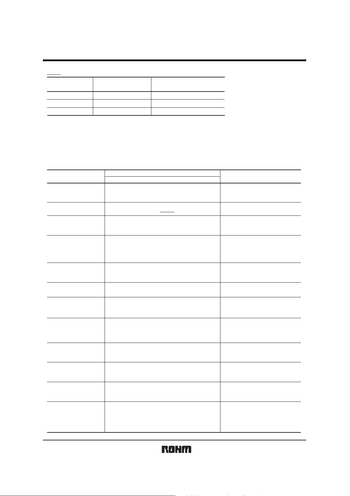
zRatings
Item Conditions Specifications
Rated power
/
3W (MCR18 1 / 4W)
Power must be derated according to the power derating curve in
Figure 1 when ambient temperature exceeds 70
100
80
60
40
POWER LOAD (%)
20
0
−55 0 70 100 155
AMBIENT TEMPERAT
URE (°C)
Fig.1
°
C
.
0.33W (1 / 3W)
at 70
°C
Rated voltage
Nominal resistance See Table 1.
Operating temperature
The voltage rating is calculated by the following equation.
If the value obtained exceeds the limiting element voltage,
the voltage rating is equal to the maximum operating voltage.
E: Rated voltage (V)
E= P×R
P: Rated power (W)
R: Nominal resistance (Ω)
Limiting element voltage
°
C
to +155°
−55
C
200V
Rev.F 1/4
ESR18
Resistors
Table 1
Resistance tolerance
D (±0.5%)
F (±1%)
J (±5%)
Resistance range
≤ R
≤ 1M (E24)
10
1
≤ R
≤ 10M (E24)
1
≤ R
≤ 10M
(Ω)
(E24)
Resistance temperature coefficient
(ppm / °
±100
±100
±200
C
)
zBefore using components in circuits where they will be exposed to transients such as pulse loads (short–duration, high–level lo ads), be certain to evaluate the
component in the mounted state. In addition, the reliability and performance of this component cannot be guaranteed if it is used with a steady st ate voltage that
is greater than its rated voltage.
zCharacteristics
Item Test conditions (JIS C 5201-1)
Resistance
Variation of resistance
with temperature
Overload
Guaranteed value
Resistor type
J : ±5%
F : ±1%
D : ±0.5%
See Table.1
± (2.0%+0.1Ω)
JIS C 5201-1 4.5
JIS C 5201-1 4.8
Measurement : −55 / +25 / +125°C
JIS C 5201-1 4.13
Rated voltage (current) ×2.5, 2s.
Limiting Element Voltage×2 : 400V
JIS C 5201-1 4.17
Rosin·Ethanol (25%WT)
Soldering condition : 235±5
Duration of immersion : 2.0±0.5s.
JIS C 5201-1 4.18
Soldering condition : 260±5
Duration of immersion : 10±1s.
JIS C 5201-1 4.19
Test temp. : −55
JIS C 5201-1 4.24
°C, 93%RH
40
Test time : 1,000h to 1,048h
JIS C 5201-1 4.25.1
Rated voltage (current), 70
1.5h : ON − 0.5h : OFF
Test time : 1,000h to 1,048h
JIS C 5201-1 4.25.3
°C
155
Test time : 1,000h to 1,048h
JIS C 5201-1 4.29
23±5
°C
, Immersion cleaning, 5±0.5min.
Solvent : 2-propanol
JIS C 5201-1 4.33
EIAJ ED-4701/300 Test method 304
Voltage : 3kv
R : 1.5kΩ
C : 100pF
Apply cycle : 1 time
°C
to +125°C 5cyc
°C
°C
°C
Solderability
Resistance to
soldering heat
Rapid change of
temperature
Damp heat, steady state
Endurance at 70°C
Endurance
Resistance to solvent
Bend strength of
the end face plating
Static electric
characteristics
A new uniform coating of minimum of
95% of the surface being immersed
and no soldering damage.
± (1.0%+0.05Ω)
No remarkable abnormality on the appearance.
± (1.0%+0.05Ω)
± (3.0%+0.1Ω)
± (3.0%+0.1Ω)
± (3.0%+0.1Ω)
± (1.0%+0.05Ω)
± (1.0%+0.05Ω)
Without mechanical damage such as breaks.
± (5.0%+0.05Ω)
Rev.F 2/4
 Loading...