

ROHM EMZ7 Datasheet
Transistors
General purpose transistor
(dual transistors)
EMZ7 / UMZ7N
EMZ7 / UMZ7N
!!!!
Features
1) Both a 2SA2018 chip and 2SC5585 chip in a EMT or
UMT package.
2) Mounting possible with EMT3 or UMT3 automatic
mounting machines.
3) Transistor elements are independent, eliminating
interference.
4) Mounting cost and area can be cut in half.
5) Low V
!!!!
CE(sat)
Structure
NPN / PNP epitaxial planar silicon transistor
!!!!
Equivalent Circuit
EMZ7 / UMZ7N
(3)
(2) (1)
Tr
Tr
2
1
(4) (5) (6)
!!!!
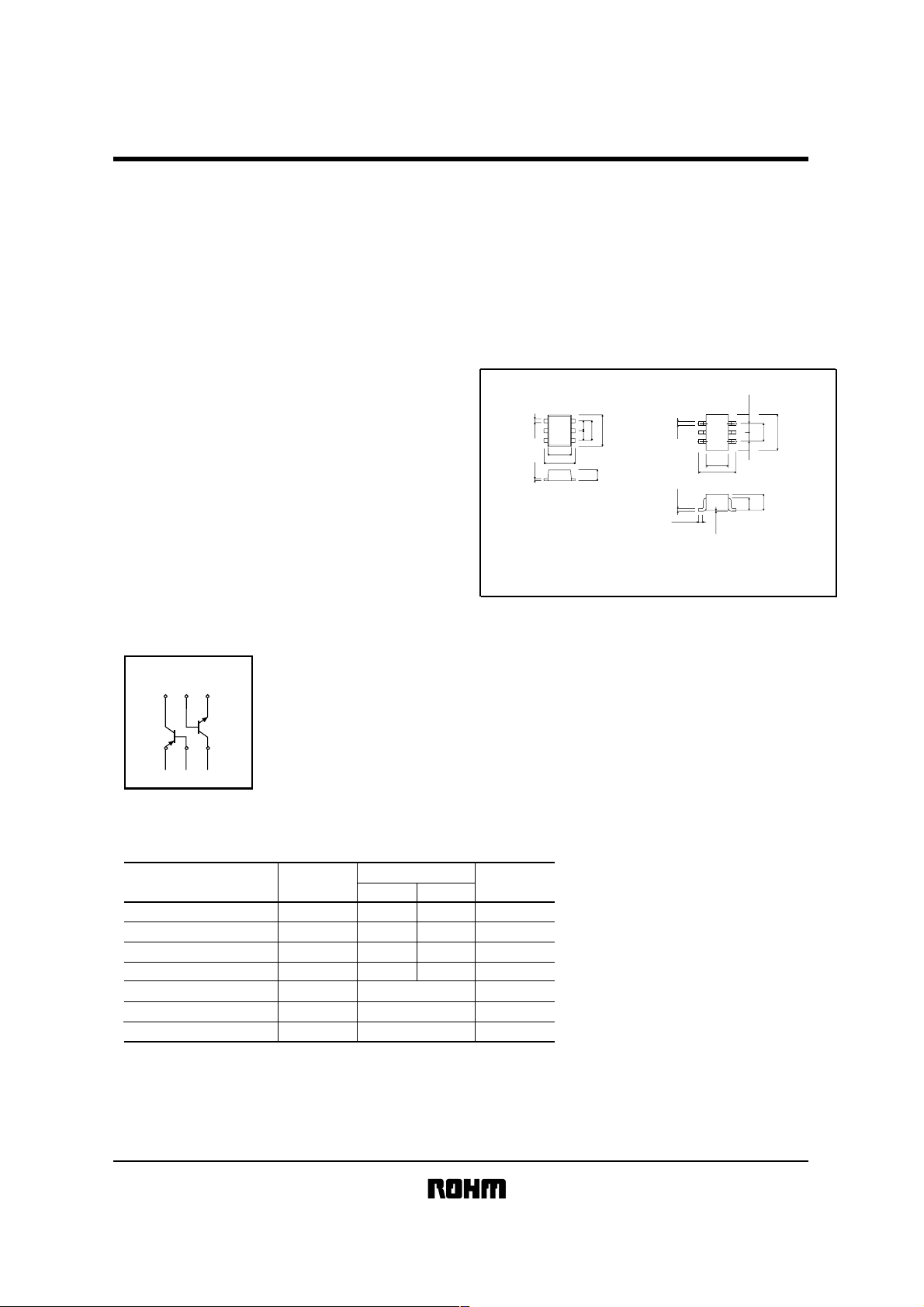
External dimensions
EMZ7
(3)
(4)
(2)(5)
0.22
(1)
(6)
1.2
1.6
0.13
Each lead has same dimensions
ROHM : EMT6
Abbreviated symbol : Z7
(Units : mm)
0.5
1.0
1.6
0.5
0.5
UMZ7N
)
4
(
)
5
(
0.2
)
6
(
1.25
2.1
0.15
0.1Min.
0to0.1
ROHM : UMT6
EIAJ : SC-88
Abbreviated symbol : Z7
)
3
(
0.65
)
2
(
1.3
0.65
0.7
2.0
0.9
)
1
(
Each lead has same dimensions
!!!! Absolute maximum ratings (Ta = 25°C)
Parameter Symbol
Collector-base voltage
Collector-emitter voltage
Emitter-base voltage
Collector current
Collector power dissipation
Junction temperature
Storage temperature
1 120mW per element must not be exceeded.
∗
V
CBO
CEO
V
V
EBO
I
P
Tj
Tstg
C
C
Limits
1
Tr
15
12
150(TOTAL)
150
−55∼+150
−500500
−15
−12
−66
Tr
2
Unit
V
V
V
mA
mW
1
∗
°C
°C
Transistors
!!!! Electrical characteristics (Ta = 25°C)
(NPN)
Tr1
Parameter Symbol
Collector-base breakdown voltage
Collector-emitter breakdown voltage
Emitter-base breakdown voltage
Collector cutoff current
Emitter cutoff current
Collector-emitter saturation voltage
DC current transfer ratio
Transition frequency
Output capacitance
Tr2 (PNP)
Parameter
Collector-base breakdown voltage
Collector-emitter breakdown voltage
Emitter-base breakdown voltage
Collector cutoff current
Emitter cutoff current
Collector-emitter saturation voltage
DC current transfer ratio
Transition frequency
Output capacitance
BV
BV
BV
I
CBO
I
EBO
V
CE(sat)
h
f
Cob
Symbol
BV
BV
BV
I
CBO
I
EBO
V
CE
h
f
Cob
CBO
CEO
EBO
FE
T
CBO
CEO
EBO
(sat)
FE
T
Min.
Typ. Max. Unit Conditions
15
12
6
−
−
−
270
−
−
Min.
−15
−12
−6
−
−
−
270
−
−
−
−
−
−
−
90
−
320
7.5
Typ.
−
−
−
−
−
−100
−
260
6.5
Max.
−250
−
−
−
0.1
0.1
250
680
−
−
−
−
−
−0.1
−0.1
680
−
−
VI
V
V
µA
µA
mV
−
MHz
pF
Unit
V
V
V
µA
µA
mV
−
MHz
pF
C=
C=
I
E=
I
V
V
C/IB=
I
V
V
V
I
I
I
V
V
I
V
V
V
10µA
1mA
10µA
CB=
EB=
CE/IC=
CE=
CB=
C=
−10µA
C=
−1mA
E=
−10µA
CB=
EB=
C/IB=
CE/IC=
CE=
CB=
EMZ7 / UMZ7N
15V
6V
200mA/10mA
2V/10mA
2V, IC=−10mA, f=100MHz
10V, IE=0A, f=1MHz
Conditions
−15V
−6V
−200mA/−10mA
−2V/−10mA
−2V, IC=10mA, f=100MHz
−10V, IE=0A, f=1MHz
!!!!Packaging specifications
Packaging type
Code
Part No.
UMZ7N
EMZ7
!!!!
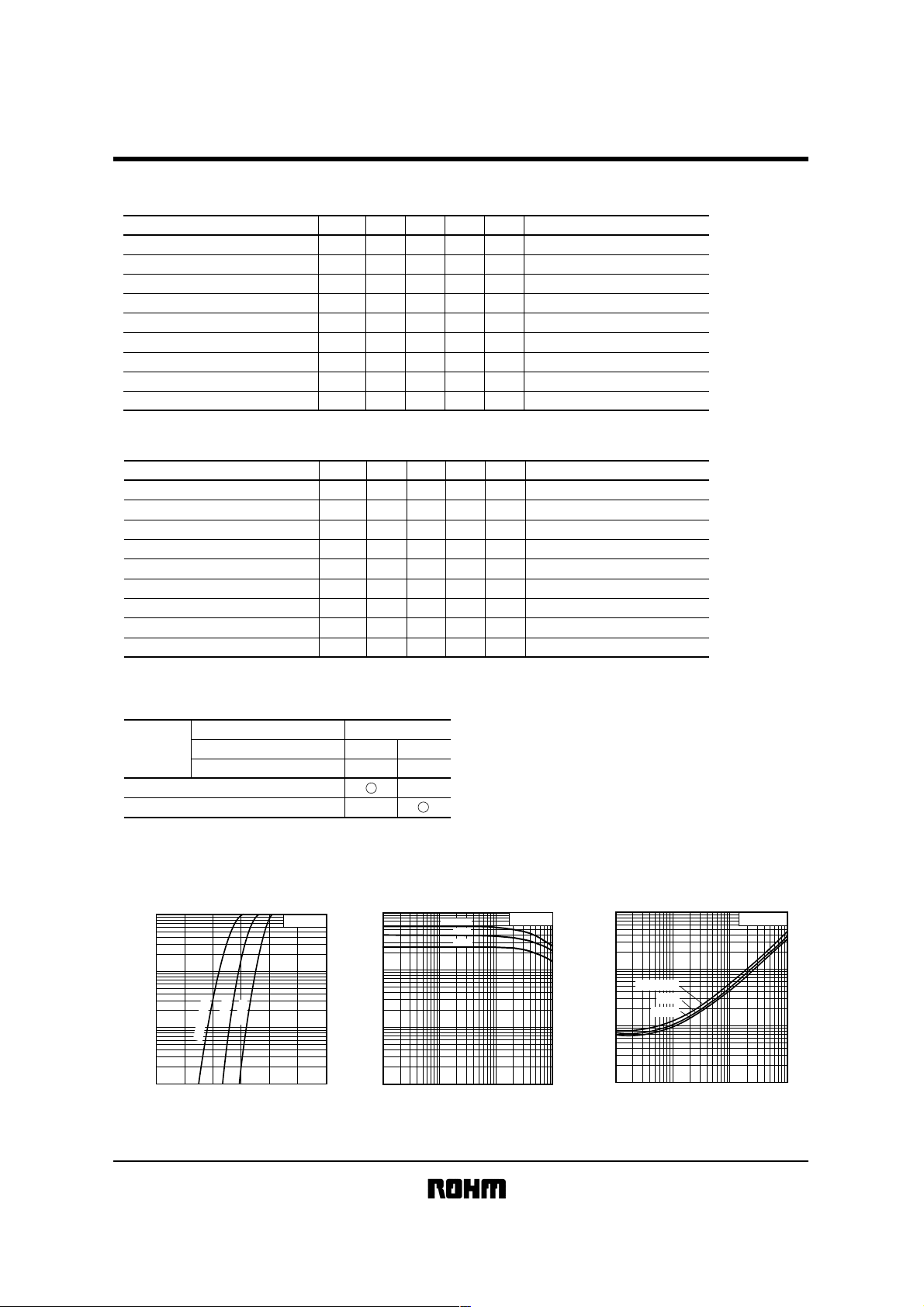
Electrical characteristic curves
(NPN)
Tr1
1000
500
(mA)
C
200
100
50
20
10
5
COLLECTOR CURRENT : I
2
1
Basic ordering unit (pieces)
C
C
C
°
°
°
25
25
40
1
−
Ta =
0
0.5 1.0 1.5
BASE TO EMITTER VOLTAGE : VBE(V)
Fig.1 Grounded emitter propagation
characteristics
VCE=2V
Taping
TR
3000
−
1000
500
FE
200
100
50
20
10
5
DC CURRENT GAIN : h
2
1
1 2 5 10 20 50 100 200 500
T2R
8000
−
Ta=125°C
25°C
−40°C
COLLECTOR CURRENT : IC(mA)
VCE=2V
Fig.2 DC current gain vs.
collector current
1000
1000
(mV)
500
(sat)
CE
200
100
50
Ta=1
25°C
20
10
5
2
1
COLLECTOR SATURATION VOLTAGE : V
25°C
−40°C
1 2 5 10 20 50 100 200 5001000
COLLECTOR CURRENT : IC(mA)
Fig.3 Collector-emitter saturation voltage
vs. collector current ( Ι )
IC/IB=20
 Loading...