

ROHM DTC144GE, DTC144GKA, DTC144GSA, DTC144GUA Schematic [ru]
DTC144GE / DTA144GUA / DTC144GKA / DTC144GSA
Transistors
Digital transistors (built-in resistor)
DTC144GE / DTC144GUA / DTC144GKA / DTC144GSA
zFeatures
1) The built-in bias resistors consist of thin-film resistors with complete isolation to allo w negati ve biasing o f the input, and
parasitic effects are almost completely eliminated.
2) Only the on / off conditions need to be set for operation, making device design easy .
3) Higher mounting densities can be achieved.
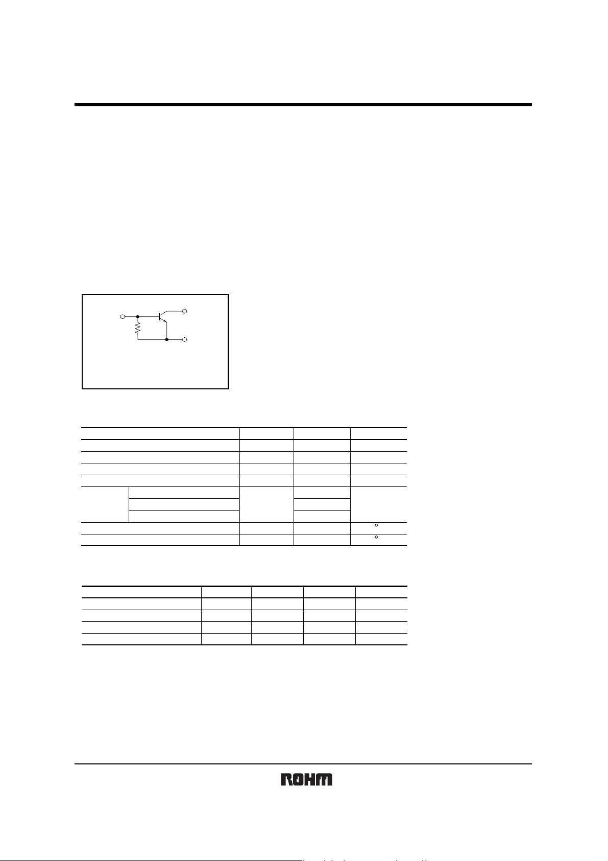
zCircuit schematic
B
E : Emitter
C : Collector
B : Base
R
C
E
zAbsolute maximum ratings (Ta=25°C)
Parameter Symbol
Collector-base voltage
Collector-emitter voltage
Emitter-base voltage
Collector current
Collector
Power
dissipation
Junction temperature
Storage temperature
DTC144GE
DTC144GUA / DTC144GKA
DTC144GSA
V
CBO
V
CEO
V
EBO
I
Pc
Tj
Tstg
C
zPackage, marking, and packaging specifications
Part No. DTC144GE
Package
Marking
Packaging code
Basic ordering unit (pieces)
EMT3
K26
TL
3000
DTC144GUA
UMT3
K26
T106
3000
Limits
50
50
5
100
150
200
300
150
−55 to +150
DTC144GKA
SMT3
K26
T146
3000
Unit
V
V
V
mA
mW
C
C
DTC144GSA
SPT
−
TP
5000
Rev.A 1/2
DTC144GE / DTA144GUA / DTC144GKA / DTC144GSA
Transistors
zElectrical characteristics (Ta=25°C)
Parameter
Collector-base breakdown voltage
Collector-emitter breakdown voltage
Emitter-base breakdown voltage
Collector cutoff current
Emitter cutoff current
Collector-emitter saturation voltage
DC current
Emitter-base resistance
Transition frequency
Transition frequency of the device.
∗
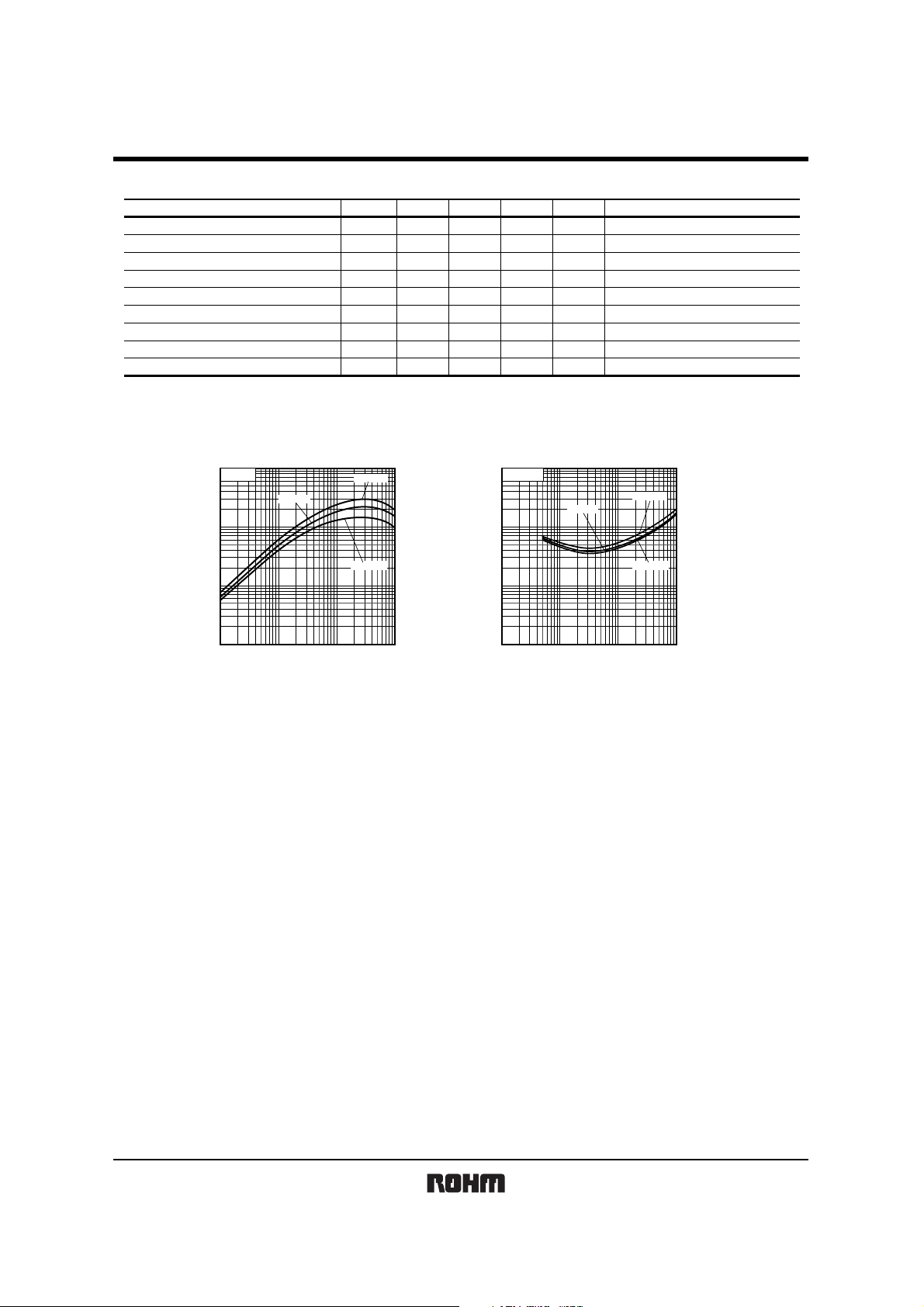
zElectrical characteristics curves
transfer ratio
1k
V
CE
=5V
500
(V)
200
FE
100
50
20
10
5
DC CURRENT GAIN : h
2
1
100µ 200µ 500µ 1m 2m 5m 10m 20m 50m 100m
Ta=25°C
COLLECTOR CURRENT : I
Fig.1 DC current gain
vs. Collector current
Symbol Min. Typ. Max. Unit Conditions
BV
CBO
BV
CEO
BV
EBO
I
CBO
I
EBO
V
CE(sat)
h
FE
R
f
T
Ta=100°C
Ta= −40°C
C
(A)
50
50
5
−
65
−
68
32.9
−
−
−
−
−
−
−
−
47
250
) (V)
sat
(
CE
COLLECTOR SATURATION VOLTAGE : V
−
−
−
0.5
130
0.3
−
61.1
−
1
I
C/IB
=20/1
500m
200m
100m
50m
20m
10m
5m
2m
1m
100µ 200µ 500µ 1m 2m 5m 10m 20m 50m 100m
COLLECTOR CURRENT : I
V
V
V
µA
µA
V
−
kΩ
MHz
Ta=25°C
I
C
=50µA
I
C
=1mA
E
=160µA
I
V
CB
=50V
V
EB
=4V
I
C
=10mA , IB=0.5mA
I
C
=5mA , VCE=5V
−
CE
=10V , IE= −5mA , f=100MHz
V
Ta=100°C
Ta= −40°C
C
(A)
Fig.2 Collector-Emitter saturation voltage
vs. Collector current
∗
Rev.A 2/2
 Loading...