


A
Digital Sound Processors for FPD TVs
32bit Audio DSP
BU9409FV
●General Description
It is a digital audio sound processor used for thin TV. Digital signal processor is Rohm original DSP only for TV
sound signal processing, and it’s cost performance is excellent. Digital inputs are two lines. Output is digital output
corresponding to 2.1ch or play of sub-voice L/R signal.
●Features
■DSP Part
Data width: 32bit (Data RAM)
Quickest machine cycle:40.7ns (512fs,fs=48kHz)
Multiplier: 32 x 24 → 56bit
Adder: 32 + 32 → 32bit
Data RAM: 256 x 32bit
Coefficient RAM: 128 x 24bit
Sampling frequency: fs=48kHz
Master clock: 512fs
(24.576MHz,fs=48kHz)
■Input output I/F
2 stereo digital signal input port : 16/20/24bit (I2S,left-align,right-align)
2 stereo digital signal output port : 16/20/24bit (I2S,left-align,right-align), S/PDIF output
■Sound signal processing function for TV
Prescaler, DC cut HPF, channel mixer, P
TREBLE, pseudo stereo, surround, P
master volume, L/R balance, postscaler, output clipper, subwoofer output processing
2
(P
Volume,P2Bass,P2Treble are Rohm original sound effect functions.)
●Applications
Flat Panel TVs (LCD, Plasma)
2
Volume(Perfect Pure Volume),BASS,MIDDLE,
2
Bass, P2Treble, 7 band parametric equalizer,
No.12083EAT03
www.rohm.com
© 2012 ROHM Co., Ltd. All rights reserved.
1/54
2012.03 - Rev.

BU9409FV
A
Technical Note
●Absolute maximum rating(Ta = 25 ° C)
Item Symbol Rating Unit
Power-supply voltage VDD 4.5 V
Allowable dissipation Pd 700 (*1) mW
operating temperature range T
Storage temperature range T
*1 7mW is decreased for 1°C when using it with Ta=25°C or more.
Operation can’t be guaranteed.
-25~+85 °C
opr
-55~+125 °C
stg
●Operating condition(Ta = - 25 ~+85°C)
Item Symbol Rating Unit
Power-supply voltage VDD 3.0~3.6 V
* 1 It isn’t Radiation-proof designed for the product.
www.rohm.com
© 2012 ROHM Co., Ltd. All rights reserved.
2/54
2012.03 - Rev.

BU9409FV
A
Technical Note
●Electrical Characteristics(Digital serial)
=3.3V unless specified, Ta=25°C
V
DD
Rating value
Unit Terms Adaptive
V
=0~3.3V
IN
Hysteresis
Input voltage
Item Symb
ol
H Level voltage VIH 2.5 - - V *1,2,3
L Level voltage VIL - - 0.8 V *1,2,3
Min. Standard Max.
Input current II -1 - +1 µA
Pull-up resistor input L current IIL -150 -100 -50 µA VIN=0V *2
Pull-down resistor input H current IIH 35 70 105 µA VIN=3.3V *3
Output voltage
H Level voltage V
L Level voltage VOL - - 0.55 V IO=0.6mA *4
2.75 - - V IO=-0.6mA *4
OH
terminal
*1
SDA terminal
Output voltage
L Level voltage V
- - 0.4 V IO=3mA *5
OL
Adaptive terminal
*1 CMOS hysteresis input terminal
SCLI(8pin), SDAI(9pin), MODE(20pin)
*2 Pull-up resistor built-in CMOS hysteresis input terminal
LRCKI(2pin), SDATA1(3pin), SDATA2(4pin), MCLK(39pin), BCKI(40pin)
*3 Pull-down resistor built-in CMOS hysteresis input terminal
RESETX(5pin), MUTEX_SP(6pin), MUTEX_DAC(7pin), ADDR(21pin)
*4 CMOS output terminal
SPDIFO(22pin), SDAO(28pin), SCLO(29pin), MUTEX_DACO(30pin), MUTEX_SPO(31pin),
RESETXO(32pin), DATAO2(33pin), DATAO1(34pin), LRCKO(35pin), BCKO(36pin), SYSCKO(37pin)
*5 Open drain output terminal
SDAI(9pin)
Electric characteristic(Analogue serial)
V
=3.3V Unless specified, Ta=25°C,RL=10kΩ, VC standard
DD
Item Symbol
Min Standard Max
whole
Circuit current IQ - 15 30 mA VDD
Regulator part
Output voltage V
1.3 1.5 1.7 V IO=100mA
REG
PLL part
Lock frequency F
- 24.576 - MHz 256fs(fs=48kHz) input
LK8
Rating Value
Unit Object pin/Condition
www.rohm.com
© 2012 ROHM Co., Ltd. All rights reserved.
3/54
2012.03 - Rev.

BU9409FV
A
●Block diagram
Technical Note
BCKI
MCLK
VSS3
39
BCKO
LRCKO
SDATAO1
SYSCLKO
3740 38 36 27
35
SDATAO2
RESETXO
33 32 31 30 29 2834
MUTEX_DACO
MUTEX_SPO
SCLO
CLK
DSP
SP
Conv.
TEST
I2S
IF
2 3 4 5 6 7 8 9 10 11 13 14 15
1
N.C.
LRCKI
SDATA1
SDATA2
RESETX
Control
IF
MUTEX_SP
MUTEX_DAC
I2C
IF
LDO15
12
SCLI
1VSS
SDAI
REG15
DVDDCORE
SDAO
N.C.
N.C.
N.C.
N.C.
2526
24 23 22 21
SPDIFO
N.C.
ADDR
PLLA
16
17 18 19 20
N.C.
VDD
ANATEST
LDOPOFF
N.C.
2VSS
PLLFIL
MODE
www.rohm.com
© 2012 ROHM Co., Ltd. All rights reserved.
4/54
2012.03 - Rev.

BU9409FV
A
●Pin Description(s)
No.
Name Description of terminals
1 N.C (*2)
2 LRCKI I2S Audio LR signal input
3 SDATA1 I2S Audio data input 1
4 SDATA2 I2S Audio data input 2
5 RESETX Reset status with “L”
6 MUTEX_SP DAC mute signal input(*1)
7 MUTEX_DAC SP mute signal input(*1)
8 SCLI I2C Forwarding clock input
9 SDAI I2C Data input output
10 VSS1 Digital I/O GND
11 DVDDCORE Connect to REG15 terminal
12 REG15 Built-in regulator voltage output
13 LDOPOFF Built-in regulator POFF signal
input
14 ANATEST Analog test monitor terminal
15 VDD Digital I/O power supply
16 N.C
17 N.C
18 PLLFIL Filter connection terminal for
PLL
19 VSS2 Digital I/O GND
20 MODE Test mode selection input
N.C.:Non Connection
(*1):signal terminal is used with D class amplifier IC (BD5446EFV etc.) for input I2S made by Rohm.
(*2) :It connects with the lead frame of a package. Please use by OPEN or GND connection.
Type
-
D
D
D
B
B
B
F
E
-
G
G
G
-
-
G
A
Technical Note
No.
21 ADDR I2C Slave address selection
22 SPDIFO S/PDIF Signal output
23 N.C
24 N.C
25 N.C
26 N.C
27 N.C
28 SDAO 2 line serial data output(*1)
29 SCLO 2 line serial clock output(*1)
30 MUTEX_DACO DAC mute signal output(*1)
31 MUTEX_SPO SP mute signal output(*1)
32 RESETXO Reset signal output(*1)
33 SDATAO2 I2S Audio data output 2
34 SDATAO1 I2S Audio data output 1
35 LRCKO I2S Audio LR signal output 1
36 BCKO I2S Audio clock output 1
37 SYSCLKO System clock output(*1)
38 VSS3 Digital I/O GND
39 MCLK Master clock input
40 BCKI I2S Audio clock input
Name Description of terminals
terminal
Type
B
C
-
-
-
-
C
C
C
C
C
C
C
C
C
C
-
H
D
www.rohm.com
© 2012 ROHM Co., Ltd. All rights reserved.
5/54
2012.03 - Rev.

BU9409FV
A
●Terminal equal circuit figure
A B C
VDD
Technical Note
VDD
VDD
VSS
VSS
VSS
D E F
VDD
VSS
VSS
VSS
G H
VDD
VSS
VDD
VSS
www.rohm.com
© 2012 ROHM Co., Ltd. All rights reserved.
6/54
2012.03 - Rev.

BU9409FV
A
A
1.Command interface
I2C bus method is used in command interface with host CPU on BU9409FV.
In BU9409FV, not only writing but read-out is possible except for some registers.
Besides the slave address in BU9409FV, one byte select address can be Specified, written and readout.
2
The format of I
MSB LSB MSB LSB MSB LSB
S Slave Address A Select Address A Data A P
S: Start condition
Slave Address: Putting up the bit of read mode (H") or write mode (L") after slave address (7bit) set with ADDR,
A: The acknowledge bit in each byte adds into the data when acknowledge is sent and received.
When data is correctly sent and received, "L" will be sent and received.
There was no acknowledge for "H".
Select Address: 1 byte select address is used in BU9409FV. (MSB first)
Data: Data-byte, data(MSB first)sent and received
P: Stop Condition
SDA
SCL
11--11.. DDaattaa wwrriittiinngg
S Slave Address A Select Address A Data A P
: From master to slave : From slave to master
ADDR=0
MSB LSB
A6 A5 A4 A3 A2 A1 A0 R/W
1 0 0 0 0 0 0 0
ADDR=1
MSB LSB
A6 A5 A4 A3 A2 A1 A0 R/W
1 0 0 0 0 0 1 0
S Slave Address
(example) 80h 20h 00h 00h 00h
: From master to slave : From slave to master
C bus slave mode is shown below.
the data of eight bits in total will be sent. (MSB first)
MSB 6 5 LSB
Start Condition
↓When SDA , SCL=”H”
Select Address A Data A Data A Data A P
Stop Condition
↑When SDA , SCL=”H”
Setting of BU9409FV slave address
Terminal setting Write-mode
ADDR
0 80h
1 82h
Technical Note
Slave-address
www.rohm.com
© 2012 ROHM Co., Ltd. All rights reserved.
7/54
2012.03 - Rev.

BU9409FV
A
Writing procedure
Step Clock Master Slave(BU9409FV) Note
1 Start Condition
2 7 Slave Address
3 1 R/W (0)
4 1 Acknowledge
5 8 Select Address Writing object register 8 bit
6 1 Acknowledge
7 8 Data Writing data 8 bit
8 1 Acknowledge
9 Stop Condition
- The select address add +1 by auto increment function when the data is transferred continuously.
Repeat of Step 7~8.
11--22.. DDaattaa rreeaaddoouutt
First of all, the readout target address(ex.&h20h) is written in &hD0 address register at the time of readout.
In the following stream, data is read out after the slave address. Please do not return the acknowledge when ending the
reception.
S Slave Address A Req_Addr A Select Address A P
(example) 80h D0h 20h
S Slave Address A Data 1 A Data 2 A A Data N Ā P
(example) 81h **h **h **h
: Master to slave, : Slave to master, A:With acknowledge, Ā:without acknowledge
Readout Procedure
Step Clock Master Slave(BU9409FV) Note
1 Start Condition
2 7 Slave Address
3 1 R/W (0)
4 1 Acknowledge
5 8 Req_Addr Address for I2C readout &hD0
6 1 Acknowledge
7 8 Select Address Readout object register 8 bit
8 1 Acknowledge
9 1 Stop Condition
10 1 Start Condition
11 7 Slave Address
12 1 R/W (1)
13 1 Acknowledge
14 8 Data Readout data 8 bit
15 1 Acknowledge
16 Stop Condition
○ The select address adds +1 by auto increment function when continuous data is transferred.
Repeat Step14~15.
&h80 (&h82)
&h80 (&h82)
&h81 (&h82)
Technical Note
www.rohm.com
© 2012 ROHM Co., Ltd. All rights reserved.
8/54
2012.03 - Rev.

BU9409FV
A
Technical Note
11--33.. CCoonnttrrooll ssiiggnnaall ssppeecciiffiiccaattiioonn
○ Bus line, I/O stage electrical specification and timing.
SDAI
t
BUF
t
LOW
t
t
R
F
t
HD;STA
SCLI
t
HD;STA
SP
t
HD;DAT
t
HIGH
t
SU;DATtSU;STA
t
SU;STO
Sr
Fig.1-1: Timing chart
Table 1-1: SDAI and SCLI bus-line characteristic (Unless specified, Ta=25, Vcc=3.3V)
Parameter Code
High-speed mode
Min. Max.
Unit
1 SCLI clock frequency fSCL 0 400 kHz
Bus-free-time between "Stop" condition and "Start"
2
condition
"Start" condition of hold-time (resending). After this period,
3
the first clock-pulse is generated.
4 LOW status hold-time of SCLI clock
5 HIGH status hold-time of SCLI clock
6 Setup time of resending “Start” condition
7 Data-hold-time
8 Data-setup time
9 Rising time of SDAI and SCL signal
10 Fall time of SDAI and SCL signal
11 Setup time of "Stop" condition
t
BUF 1.3 - μs
t
HD;STA 0.6 - μs
t
LOW 1.3 - μs
t
HIGH 0.6 - μs
t
SU;STA 0.6 - μs
t
HD;DAT 01) - μs
t
SU;DAT
t
R 20+Cb 300 ns
t
F 20+Cb 300 ns
t
SU;STO 0.6 - μs
500/250/15
0
- ns
12 Capacitive load of each bus-line Cb - 400 pF
The above-mentioned numerical values are all the values corresponding to V
IH min
and V
IL max
level.
1) To exceed an undefined area on falling edged of SCLI, transmission device should internally offer the hold-time of
300ns or more for SDAI signal(V
of SCLI signal).
IH min
2) Data-setup time changes with setup of MCLK. In MCLK=512fs, data setup time is 150ns.
In MCLK=256fs, data setup time is 250ns. In MCLK=128fs, data setup time is 500ns.
The above-mentioned characteristic is a theory value in IC design and it doesn't be guaranteed by shipment inspection.
When problem occurs by any chance, we talk in good faith and correspond.
Neither terminal SCLI nor terminal SDAI correspond to 5V tolerant. Please use it within absolute maximum rating 4.5V.
P
www.rohm.com
© 2012 ROHM Co., Ltd. All rights reserved.
9/54
2012.03 - Rev.

BU9409FV
A
Technical Note
2.Switching of data and clock
I/O system chart of BU9409FV audio data is shown below.
Digital input1
Digital input1
Digital input2
Digital input2
SEL1
SDATA1
SDATA2
Audio DSP
(BU9409FV)
S-P
conversi
on1
S-P
conversi
on2
DSP CLK
(512fs)
DSP operation part
This part is performanced by hardware.
Main Main
Bass
Func.
Main
PLLA
mclk_
P-EQ
div
MCLK
SEL3
Sub
Treble
plla_
div
SYSCLKO
(256fs)
EVR
I2C
Sub
Control I/F
RESET
SEL2
MODE
Convers
Convers
Convers
・・・
ADDR
P-S
SDATAO1(Main)
ion1
P-S
SDATAO2(Sub)
ion2
P-S
ion3
SPDIFO
D Class amp output
D Class amp output
(Sub Woofer)
Optical output
BU9409FV has 2 digital stereo input and 3 digital stereo output with the same sampling rate.
Output from DSP operation part is converted into I
2
S mode digital output or S/PDIF mode digital serial output.
System clock uses master clock input from MCLK terminal, makes 512fs multiplying clock in PLL block. Moreover, 256fs
synchronous clock can be output from terminal SYSCLKO, and the clock is supplied to external DAC or D class SP
amplifier.
SPDIFO and output data selection of SDATAO1 and SDATAO2 should unify the DSP processing after (post) or processing
before (pre) with all outputs.
22--11.. SS--PP ccoonnvveerrssiioonn11 iinnppuutt ddaattaa sseelleeccttiioonn((SSEELL11))
Default = 0
Select Address Value Operating Description
&h03 [ 0 ]
0 Input data from SDATA1
1 Input data from SDATA2
22--22.. SS--PP ccoonnvveerrssiioonn22 iinnppuutt ddaattaa sseelleeccttiioonn((SSEELL11))
Default = 0
Select Address Value Operating Description
&h03 [ 4 ]
0 Input data from SDATA1
1 Input data from SDATA2
22--33.. OOuuttppuutt ddaattaa sseelleeccttiioonn((SSEELL22)) ttoo PP--SS ccoonnvveerrssiioonn11 ((SSDDAATTAAOO11 TTeerrmmiinnaall))
Default = 0
Select Address Value Operating Description
&h04 [ 1:0 ]
0 Main data output after DSP is processed.
1 Sub data output after DSP is processed.
2 Main data output before DSP is processed.
3 Sub data output before DSP is processed.
(Main SP)
www.rohm.com
© 2012 ROHM Co., Ltd. All rights reserved.
10/54
2012.03 - Rev.

BU9409FV
A
Technical Note
22--44.. OOuuttppuutt ddaattaa sseelleeccttiioonn((SSEELL22)) ttoo PP--SS ccoonnvveerrssiioonn22 ((SSDDAATTAAOO22 TTeerrmmiinnaall))
Default = 0
Select Address Value Operating Description
&h04 [ 5:4 ]
22--55.. SSPPDDIIFFOO TTeerrmmiinnaall oouuttppuutt ddaattaa sseelleeccttiioonn((SSEELL22))
Default = 0
Select Address Value Operatin
&h05 [ 1:0 ]
22--66.. SSyysstteemm cclloocckk sseelleeccttiioonn((SSEELL33))
Select the DSP clock supplied to S-P conversion1、S-P conversion2、DSP、P-S conversion1、P-S conversion2、S/PDIF
output part.
Default = 0
Select Address Value Operating Description
&h08 [ 5:4 ]
After power on or reset released, system block selection uses clock(even if not 512fs is ok) input from terminal MCLK to
receive I2C command and initialize BU9409. Then set the dividing frequency ratio of PLL block (mclk_div, pll_div) that is
suitable for the clock frequency from terminal MCLK , when PLL_512fs clock from PLL is steady, set &h08 = 10h.
Dividing frequency ratio setting of PLL block which corresponding to input clock from terminal MCLK
22--77..
Sampling rate of input clock Setting of mclk_div
512fs(24.576MHz、fs=48kHz)
256fs(12.288MHz、fs=48kHz)
128fs(6.144MHz、fs=48kHz)
0 Sub data output after DSP is processed.
1 Main data output after DSP is processed.
2 Sub data output before DSP is processed.
3 Main data output before DSP is processed.
0 Main data output after DSP is processed.
1 Sub data output after DSP is processed.
2 Main data output before DSP is processed.
3 Sub data output before DSP is processed.
0 Chose the input from a MCLK terminal as a clock.
1 Chose the PLL output as a clock.
2
Chose the input from a SDATA2terminal as a clock. (used for IC test).
3
&hF3
10h 01h 23h
08h 01h 23h
04h 01h 23h
Setting of pll_div
&hF5
g Description
PLL initialization
&hF6
www.rohm.com
© 2012 ROHM Co., Ltd. All rights reserved.
11/54
2012.03 - Rev.

BU9409FV
A
Technical Note
3. S-P Conversion 1, S-P Conversion 2
BU9409FV has two serial-parallel conversion circuits. (S-P conversion 1, S-P conversion 2)
S-P conversion 1 & 2 receives the audio data of three-wire serial input from terminal and converts it into parallel data.
They select the inputs from LRCKI (2pin), BCKI (40pin), SDATA1 (3pin), and SDATA2(4pin).
Input format has IIS method, left-justified method and right-justified method. Moreover, for bit clock frequency, 64fs or 48fs
can be selected, and when 48fs is selected, the input format becomes the fixed right-justification. In addition, 16bit, 20bit and
24bit inputs can be selected respectively.
Timing chart of each transmission method is shown in the diagram below.
IIS method
IIS方式
LRCKI
1 2 3 4 5 6 7 8 9 10 11 12 13 14 15 16 17 18 19 20 21 22 23 24 25 26 27 28 29 30 31 32 1 2 3 4 5 6 7 8 9 10 11 12 13 14 15 16 17 18 19 20 21 22 23 24 25 26 27 28 29 30 31 32
BCKI
MSB LSB
S
DATAI
16bit
MSB LSB
S
16bit
20bit
24bit
20bit
24bit
Left-justified method
左詰方式
LRCKI
1 2 3 4 5 6 7 8 9 10 11 12 13 14 15 16 17 18 19 20 21 22 23 24 25 26 27 28 29 30 31 32 1 2 3 4 5 6 7 8 9 10 11 12 13 14 15 16 17 18 19 20 21 22 23 24 25 26 27 28 29 30 31 32
BCKI
MSB L SB
S
DATAI
16bit
20bit
24bit
MSB L SB
S
16bit
20bit
24bit
Right-justified method
右詰方式
LRCKI
1 2 3 4 5 6 7 8 9 10 11 12 13 14 15 16 17 18 19 20 21 22 23 24 25 26 27 28 29 30 31 32 1 2 3 4 5 6 7 8 9 10 11 12 13 14 15 16 17 18 19 20 21 22 23 24 25 26 27 28 29 30 31 32
BCKI
DATAI
MSB LSB
S
16bit
20bit
24bit
MSB LSB
S
16bit
20bit
24bit
48fs
LRCKO
1 2 3 4 5 6 7 8 9 10 11 12 13 14 15 16 17 18 19 20 21 22 23 24 1 2 3 4 5 6 7 8 9 10 11 12 13 14 15 16 17 18 19 20 21 22 23 24
BCKO
DATAO
MSB LSB
S
16bit
20bit
24bit
MSB L SB
S
16bit
20bit
24bit
www.rohm.com
© 2012 ROHM Co., Ltd. All rights reserved.
12/54
2012.03 - Rev.

BU9409FV
A
Technical Note
33--11.. TThhrreeee--wwiirree sseerriiaall iinnppuutt’’ss bbiitt cclloocckk ffrreeqquueennccyy sseettttiinngg
Default = 0
Select Address Value Operational explanation
S-P conversion1, S-Pconversion2
&h0B [ 4 ]
33--22.. TThhrreeee--wwiirree sseerriiaall iinnppuutt’’ss ffoorrmmaatt sseettttiinngg
Default = 0
Select Address Value Operational explanation
S-P conversion1 &h0B
S-P conversion2 &h0C
33--33.. TThhrreeee--wwiirree sseerriiaall iinnppuutt’’ss ddaattaa bbiitt wwiiddtthh sseettttiinngg
Default =
S-P conversion1 &h0B
S-P conversion2 &h0C
0
Select Address Value Operational explanation
[ 3:2 ]
[ 3:2 ]
[ 1:0 ]
[ 1:0 ]
0 64fs method
1 48fs method
0 IIS method
1 left-justified method
2 right-justified method
0 16 bit
1 20 bit
2 24 bit
www.rohm.com
© 2012 ROHM Co., Ltd. All rights reserved.
13/54
2012.03 - Rev.

BU9409FV
A
Technical Note
4. Digital sound processing(DSP)
BU9409FV’s Digital Sound Processing(DSP) consists of special hardware most suitable to Thin TV.
BU9409FV uses this special DSP to perform the following processing.
Prescaler, DC Cut HPF, Channel Mixer, P
2
Volume(Perfect Pure Volume), BASS, MIDDLE, TREBLE,
Pseudo Stereo, Surround, P2Bass, P2Treble, 7 Band・Parametric Equalizer, Master Volume, L/R Balance, PostScaler,
Output Clipper、 Sub-woofer output Processing.
DDSSPP OOuuttlliinnee aanndd SSiiggnnaall FFllooww
Data width: 32 bit (DATA RAM)
Machine cycle: 40.7ns (512fs, fs=48kHz)
Multiplier: 32×24 → 56 bit
Adder: 32+32
Data RAM: 256×32 bit
→ 32 bit
MUX
Data
Input
RAM
MUX
0
M
U
X
Coefficient RAM: 128×24 bit
Sampling frequency: fs=48kHz
Master clock: 512fs (24.576MHz, fs=48kHz)
ADD
Acc
Digital signal from 16bit to 24bit is inputted to DSP,
Output
and it is extended by +8bit(+42dB) as overflow margin on the upper side.
The clip process is performed in DSP when the process exceeding this range is performed.
Input1
Input2
Pre
scaler
HPF
Channel
mixer
Digital Audio Processing Signal Flow
P2Volume
BASS
MIDDLE
TREBLE
Scaler
Pseude
stereo
1
surround
&
P2Bass P2Treble
Channel
Channel
mixer
mixer
Scaler
LPF
7Band
P-EQ
2
3band
P-EQ
EVR
&
Blance
EVR
&
Balance
Post
scaler
&
Clipper
Post
scaler
&
Clipper
44--11.. PPrreessccaalleerr
When digital signal is inputted to audio DSP, if the level is full scale input and the process of surround or equalizer is
performed, then it overflows, therefore the input gain is adjusted by prescaler.
Adjustable range is +24dB to -103dB and can be set by the step of 0.5dB.
Prescaler does not incorporate the smooth transition function.
Default = 30h
Select Address Operational explanation
&h20 [ 7:0 ]
command gain
00
01 +23.5dB
30
31
32
……
FE
FF
+24dB
0dB
-0.5dB
-1dB
-103dB
-∞
……
Coefficient
operation
Circuit
Coefficient
RAM
Decoder
circuit
Main output
Sub output
www.rohm.com
© 2012 ROHM Co., Ltd. All rights reserved.
14/54
2012.03 - Rev.

BU9409FV
A
Technical Note
44--22.. DDCC CCuutt HHPPFF
The DC offset component of digital signal inputted to the audio DSP is cut by this HPF.
The cutoff frequency fc of HPF is 1Hz, and first-order filter is used.
Default = 0
44--33.. CChhaannnneell mmiixxeerr
It performs the setting of mixing the sounds of left channel & right channel of digital signal inputted to the audio DSP.
Here the stereo signal is made to be monaural.
The data inputted to Lch of DSP is mixed.
Default = 0
The data inputted to Rch of DSP is mixed.
Default = 0
Select Address Value Operational explanation
&h21 [ 0 ]
Select Address Value Operational explanation
&h22 [ 7:6 ]
Select Address Value Operational explanation
&h22 [ 5:4 ]
0 Not using the DC Cut HPF
1 Using the DC Cut HPF
0 Inputting the Lch data
1 Inputting the data of (Lch + Rch) / 2
2 Inputting the data of (Lch + Rch) / 2
3 Inputting the Rch data
0 Inputting the Rch data
1 Inputting the data of (Lch + Rch) / 2
2 Inputting the data of(Lch + Rch) / 2
3 Inputting the Lch data
www.rohm.com
© 2012 ROHM Co., Ltd. All rights reserved.
15/54
2012.03 - Rev.

BU9409FV
A
2
2
44--44.. P
P
VVoolluummee ((PPeerrffeecctt PPuurree VVoolluummee))
There are some scenes in which sound suddenly becomes large like plosive sound in TV Commercial or Movie.
2
Volume function automatically controls the volume and adjusts the output level.
P
In addition, it also adjusts in such a way that a whispery sound can be heard easily.
2
Volume function operates in the fields of (1), (2) & (3) divided according to input level.
P
(1) at the time of V
inf
I
(-∞)~V
Noise is prevented from being lifted by P
(2) When input level is over V
V
= VI + α
O
α: Lifting the Whole output level by the offset value α
(3) When output level V
V
O
= K・VI + α
O
min
I
and output is below V
min
I
exceeds V
Omax
2
Volume function.
Omax
V
O
V
Omax
P2V_MAX
(2)
K: Slope for suppressing of D range (P2V_K)
It is also possible to set an output level constant.
2
Selection of using the P
Default = 0
Volume function.
V
Omin
α
V
Oinf
(1)
V
V
Iinf
Imin
P2V_MIN
Select Address Value Operational explanation
&h33 [ 7 ]
0 Not using the P2Volume function
1 Using the P2Volume function
Setting of V
In order to cancel that noise etc. is lifted by P
2
Volume functions.
P
Default = 00h
min
I
2
Volume, the P2V_MIN sets the minimum level at which (to the minimum) the
command
Select Address Operational explanation
&h34 [ 4:0 ]
command gain
00 -∞
01
02
03
04
05
06
07
-30dB
-32dB
-34dB
-36dB
-38dB
-40dB
-42dB
command gain
-44dB
08
09
-46dB
0A
-48dB
-50dB
0B
0C
-52dB
0D
-54dB
0E
-56dB
0F
-58dB
command gain
-60dB
10
11
-62dB
12
-64dB
-66dB
13
14
-68dB
15
-70dB
16
-72dB
17
-74dB
コマンド値 ゲイン
-76dB
18
19
-78dB
1A
-80dB
-82dB
1B
1C
-84dB
1D
-86dB
1E
-88dB
1F
-90dB
Technical Note
K
(3)
0dB
P2V off
V
I
Setting of V
max
O
P2V_MAX sets the output suppression level. It represents the output level V
case of setting of P2V_K = “0h”(slope is 0).
Default = 00h
Select Address Operational explanation
&h35 [ 4:0 ]
www.rohm.com
© 2012 ROHM Co., Ltd. All rights reserved.
command gain
00 0dB
01
-1dB
-2dB
02
-3dB
03
04
-4dB
05
-5dB
06
-6dB
07
-7dB
16/54
command gain
08
-8dB
09
-9dB
-10dB
0A
-11dB
0B
0C
-12dB
0D
-13dB
0E
-14dB
0F
-15dB
at the time of input level VI = 0dB in the
max
O
command gain
10
11
12
13
14
15
16
17
-16dB
-17dB
-18dB
-19dB
-20dB
-21dB
-22dB
-23dB
command gain
18
-24dB
19
-25dB
-26dB
1A
-27dB
1B
1C
-28dB
1D
-29dB
1E
-30dB
1F
-
2012.03 - Rev.

BU9409FV
A
Setting of K
P2V_K sets the slop of D range. It sets the P2V_MAX = “1Eh”(-30dB) and represents the output level V
input level V
= 0dB.
I
Default = 00h
Select Address Operational explanation
&h36 [ 3:0 ]
command gain
0 -30dB
1
-28dB
-26dB
2
-24dB
3
4
-22dB
5
-20dB
6
-18dB
7
-16dB
comman
8
9
A
B
C
D
E
F
gain
-14dB
-12dB
-10dB
-8dB
-6dB
-4dB
-2dB
0dB
Setting of α
P2V_OFS makes small voice easy to be heard because the whole output level is lifted.
Default = 00h
Select Address Operational explanation
&h37 [ 4:0 ]
command gain
00 0dB
01
02
03
04
05
06
07
+1dB
+2dB
+3dB
+4dB
+5dB
+6dB
+7dB
command gain
08
09
0A
0B
0C
0D
0E
0F
+8dB
+9dB
+10dB
+11dB
+12dB
+13dB
+14dB
+15dB
command gain
10
+16dB
11
+17dB
+18dB
12
+19dB
13
14
+20dB
15
+21dB
16
+22dB
17
+23dB
Setting 1 of transition time at the time of attack
2
A_RATE is the setting of transition time when the state of P
Default = 0
Volume function is transited to (2)→(3).
Select Address Operational explanation
&h38 [ 6:4 ]
command A_RATE time
0 1ms
1 2ms
2
3
3ms
4ms
command
4
5
6
7
A_RATE time
10ms
20ms
40ms
Setting 1 of transition time at the time of recovery
2
R_RATE is the setting of transition time when the state of P
Default = 0h
Volume function is transited to (3)→(2).
Select Address Operational explanation
&h38 [ 3:0 ]
command R_RATE time
0 0.25s
1
2
3
4
5
6
7
0.5s
0.75s
1s
1.25s
1.5s
2s
2.5s
command
8
9
A
B
C
D
E
F
R_RATE time
3s
4s
5s
6s
7s
8s
9s
10s
Technical Note
max
O
command gain
18
19
1A
1B
1C
1D
1E
1F
5ms
at the time of
+24dB
-
-
-
-
-
-
-
www.rohm.com
© 2012 ROHM Co., Ltd. All rights reserved.
17/54
2012.03 - Rev.

BU9409FV
A
Technical Note
Explanation of A_RATE,R_RATE(field transition of (2)<->(3))
Input
V
I
Time
T
Field (2) Field (2)Field (3)
V
Omax
Output
V
O
Time
T
Attack operation
A_RATE
The time from exceeding the
attack operation detection level
V
till the attack operation's
Omax
transition to Field (3) is
completed
Recovery operation
R_RATE
The time from falling below the
recovery operation detection
level V
operation's transition to Field
(2) is completed
till the recovery
Omax
Setting 1 of attack detection time
2
A_TIME is the setting of the initiation of P
Volume function’s transition operation. If output level at the time of transiting to
(2)→(3) continues for more then A_TIME time in succession, then the state transition of P
Default = 0
Select Address Operational explanation
&h39 [ 6:4 ]
command A_TIME
command
0 0.5ms
1 1ms
2
3
Setting 1 of recovery detection time
2
R_TIME is the setting of the initiation of P
(3)→(2) continues for more then R_TIME time in succession, then the state transition of P
Default = 0
Select Address Operational explanation
&h39 [ 2:0 ]
Volume function’s transition operation. If output level at the time of transiting to
command R_TIME
1.5ms
2ms
command
0 50ms
1 100ms
2
3
150ms
200ms
2
Volume is started.
A_TIME
4
5
6
7
2
Volume is started.
3ms
4ms
5ms
6ms
4
5
6
7
R_TIME
300ms
400ms
500ms
600ms
www.rohm.com
© 2012 ROHM Co., Ltd. All rights reserved.
18/54
2012.03 - Rev.

BU9409FV
A
Explanation of A_RATE_Low,R_RATE_Low(field transition of (1)<->(2))
Technical Note
V
Imin
Input
V
I
Tme T
Field (1) Field (1)Field (2)
V
Omin
Output
V
O
Time T
Recovery operation
R_RATE_Low
The time from falling
below the recovery
operation detection level
V
till the recovery
Imin
operation's transition to
Field (2) is completed
Attack operation
A_RATE_Low
The time from exceeding
the attack operation
detection level V
attack operation's transition
to Field (1) is completed
Imin
till the
Setting 2 of the transition time at the time of attack
A_RATE_LOW is the setting of transition time when the state of P
Default = 0
2
Volume function is transited to (2)→(1).
Select Address Operational explanation
Command
0 1ms
&h3A [ 6:4 ]
1 2ms
2
3
Setting 2 of the transition time at the time of recovery
R_RATE_LOW is the setting of transition time when the state of P
Default = 0 (Caution) This setting value is not reflected in BU9409FV. The value of &h38 [3:0] is set up.
A_RATE_LOW Time
Command
A_RATE_LOW Time
4
5
3ms
4ms
2
Volume function is transited to (1)→(2).
6
7
Select Address Operational explanation
&h3A [ 2:0 ]
Setting 2 of attack・recovery detection time
AR_TIME_LOW is the setting of the initiation of P
Command
0 1ms
1 2ms
2
3
2
Volume function’s transition operation. If output level at the time of
R_RATE_LOW Time
3ms
4ms
Command
4
5
6
7
R_RATE_LOW Time
transiting to (1)<->(2) continues for more then AR_TIME time in succession, then the state transition of P
Default = 0
Select Address Operational explanation
&h3B [ 6:4 ]
Command
0 0.5ms
1 1ms
2
3
AR_TIME_LOW
1.5ms
2ms
Command
4
5
6
7
AR_TIME_LOW
3ms
4ms
5ms
6ms
5ms
10ms
20ms
40ms
5ms
10ms
20ms
40ms
2
Volume is started.
www.rohm.com
© 2012 ROHM Co., Ltd. All rights reserved.
19/54
2012.03 - Rev.

BU9409FV
A
○Pulse sound detection and High-speed recovery function(functioning only at the time of transition of (2)<->(3))
2
Volume function makes the P2Volume also compatible with large pulse sounds (clapping of hands, fireworks & shooting
P
2
etc.) in addition to normal P
operation (R_RATE) is performed at 4 or 8 times the speed of normal attack operation or recovery operation.
Selection of using the pulse sound detection function.
Default = 0
Select Address Value Operational explanation
&h3BC[ 7 ]
Selection of operating times of Recovery Time (R_RATE) in the case of using the pulse sound detection function
Default = 0
Select Address Value Operational explanation
&h3C [ 3 ]
Selection of pulse sound detection time
Default = 0
Select Address Operational explanation
&h3C [ 6:4 ]
Setting of operating level of pulse sound detection function
Operation is started by the difference between the presently detected value and the last value as a standard.
Default = 0
Select Address Operational explanation
&h3C [ 2:0 ]
Example) Present detection level A : -10dB → 10^(-10/20) = 0.32
The last detection level B : -30dB → 10^(-30/20) = 0.032
A – B : 0.32 – 0.032 = 0.288 → Operating by the setting of command ”4” to ”7”.
Volume operation. When large pulse sound is inputted, attack operation (A_RATE) or recovery
0 Not using of pulse sound detection function
1 Using of pulse sound detection function
0
1
Operating at 4 times the speed corresponding to the setting time of
R_RATE
Operating at 8 times the speed corresponding to the setting time of
R_RATE
Command
Command
Detection time
0 100us
1 200us
2
3
400us
1ms
Detection level
0 Over 1.002
1 Over 0.709
2
3
Over 0.502
Over 0.355
Command
4
5
6
7
Command
Detection time
4
5
6
7
Technical Note
2ms
5ms
10ms
20ms
Detection level
Over 0.251
Over 0.178
Over 0.126
Over 0.089
www.rohm.com
© 2012 ROHM Co., Ltd. All rights reserved.
20/54
2012.03 - Rev.

BU9409FV
A
Technical Note
44--55.. BBAASSSS
BASS of TONE Control can use Peaking filter or Low-shelf filter.
The setting is converted, in the IC, into digital filter’s coefficients (b0, b1, b2, a1, a2)by selecting the F
transmitted to coefficient RAM. The switching shock noise at the time of alteration of setting can be prevented by the smooth
transition function.
○BASS Control
Selection of filter types
Selection of smooth transition function
Selection of smooth transition time
Setting of smooth transition start
In the case of using the smooth transition function, after being transmitted, by the &h40[0] command, to the coefficient RAM
for smooth transition, the alteration of BASS’s coefficients is completed by using this command.
What is necessary is the time of waiting, which is more than the time selected by the setting of Bass smooth transition time,
from the time the BASS smooth transition start (&h4C[0] = “1”) is executed until the following command is sent. Please
make sure to perform the Bass smooth transition stop(&h4C[0] = “0”) after the smooth transition is completed.
Default = 0
Select Address Value Operational explanation
Default = 0
Select Address Value Operational explanation
Default = 0
Select Address Value Operational explanation
Default = 0
Select Address Value Operational explanation
&h40 [ 7 ]
&h40 [ 6 ]
&h40 [ 5:4 ]
&h4C [ 0 ]
0 Peaking filter
1 Low-shelf filter
0 Using BASS smooth transition function
1 Not BASS using smooth transition function
0 21.4ms
1 10.7ms
2 5.4ms
3 2.7ms
0 BASS smooth transition stop
1 BASS smooth transition start
,Q and Gain, and
0
www.rohm.com
© 2012 ROHM Co., Ltd. All rights reserved.
21/54
2012.03 - Rev.

BU9409FV
A
Technical Note
Setting of the Start of transmitting to coefficient RAM
In the case of using the smooth transition, it is transmitted to the coefficient RAM for smooth transition. In the case of not
using of the smooth transition, it is transmitted directly to the coefficient RAM.
Default = 0
Select Address Value Operational explanation
&h40 [ 0 ]
0 BASS coefficient transmission stop
1 BASS coefficient transmission start
selection of frequency(F
Default = 0Eh
0
)
Select Address Operational explanation
&h41 [ 5:0 ]
Command
00
01
02
03
04
05
06
07
Frequency
20Hz
22Hz
25Hz
28Hz
32Hz
35Hz
40Hz
45Hz
Command
08
09
0A
0B
0C
0D
0E
0F
Frequency
50Hz
56Hz
63Hz
70Hz
80Hz
90Hz
100Hz
110Hz
Command
10
11
12
13
14
15
16
17
Frequency
125Hz
140Hz
160Hz
180Hz
200Hz
220Hz
250Hz
280Hz
Command
18
19
1A
1B
1C
1D
1E
1F
Frequency
315Hz
350Hz
400Hz
450Hz
500Hz
560Hz
630Hz
700Hz
Command
20
21
22
23
24
25
26
27
Frequency
800Hz
900Hz
1kHz
1.1kHz
1.25kHz
1.4kHz
1.6kHz
1.8kHz
Command
28
29
2A
2B
2C
2D
2E
2F
Frequency
2kHz
2.2kHz
2.5kHz
2.8kHz
3.15kHz
3.5kHz
4kHz
4.5kHz
Command
30
31
32
33
34
35
36
37
Frequency
5kHz
5.6kHz
6.3kHz
7kHz
8kHz
9kHz
10kHz
11kHz
Command
Frequency
12.5kHz
38
39
14kHz
16kHz
3A
3B
18kHz
20kHz
3C
3D
-
-
3E
3F
-
Selection of quality factor (Q)
Default = 4h
Select Address Operational explanation
&h42 [ 3:0 ]
Command
Quality factor
0
1
2
3
4
5
6
7
0.33
0.43
0.56
0.75
1.0
1.2
1.5
1.8
Selection of Gain
Default = 40h
Select Address Operational explanation
&h43 [ 6:0 ]
Command Gain
1C -18dB
…
3E -1dB
3F
40
41
…
64
If the coefficient of b0, b1, b2, a1, and a2 exceeds ±4, it may not operate normally.
Command
8
9
A
B
C
D
E
F
…
-0.5dB
0dB
+0.5dB
+1dB42
…
+18dB
Quality factor
2.2
2.7
3.3
3.9
4.7
5.6
6.8
8.2
www.rohm.com
© 2012 ROHM Co., Ltd. All rights reserved.
22/54
2012.03 - Rev.

BU9409FV
A
Technical Note
44--66.. MMIIDDDDLLEE
MIDDLE of TONE Control uses Peaking filter.
The setting is converted, in the IC, into digital filter’s coefficients (b0, b1, b2, a1, a2)by selecting the F,Q and Gain, and
transmitted to coefficient RAM. The switching shock noise at the time of alteration of setting can be prevented by the smooth
transition function.
○MIDDLE Control
Selection of smooth transition function
Selection of smooth transition time
Setting of smooth transition start
In the case of using the smooth transition function, after being transmitted, by the &h44[0] command, to the coefficient RAM
for smooth transition, the alteration of MIDDLE’s coefficients is completed by using this command.
What is necessary is the time of waiting, which is more than the time selected by the setting of MIDDLE smooth transition
time, from the time the MIDDLE smooth transition start (&h4C[1] = “1”) is executed until the following command is sent.
Please make sure to perform the MIDDLE smooth transition stop(&h4C[1] = “0”) after the smooth transition is completed.
Setting of the Start of transmitting to coefficient RAM
In the case of using the smooth transition, it is transmitted to the coefficient RAM for smooth transition. In the case of not
using of the smooth transition, it is transmitted to the direct coefficient RAM.
Default = 0
Select Address Value Operational explanation
Default = 0
Select Address Value Operational explanation
Default = 0
Select Address Value Operational explanation
Default = 0
Select Address Value Operational explanation
&h44 [ 6 ]
&h44 [ 5:4 ]
&h4C [ 1 ]
&h44 [ 0 ]
0 Using MIDDLE smooth transition function
1 Not MIDDLE using smooth transition function
0 21.4ms
1 10.7ms
2 5.4ms
3 2.7ms
0 MIDDLE smooth transition stop
1 MIDDLE smooth transition start
0 MIDDLE coefficient transmission stop
1 MIDDLE coefficient transmission sart
www.rohm.com
© 2012 ROHM Co., Ltd. All rights reserved.
23/54
2012.03 - Rev.

BU9409FV
A
Selection of frequency(F0)
Default = 0Eh
Select Address Operational explanation
&h45 [ 5:0 ]
Selection of quality factor(Q)
Default = 4h
Select Address Operational explanation
&h46 [ 3:0 ]
Selection of Gain
Default = 40h
Select Address Operational explanation
&h47 [ 6:0 ]
If the coefficient of b0, b1, b2, a1, and a2 exceeds ±4, it may not operate normally.
Command
00
01
02
03
04
05
06
07
Frequency
20Hz
22Hz
25Hz
28Hz
32Hz
35Hz
40Hz
45Hz
Command
08
09
0A
0B
0C
0D
0E
0F
Frequency
50Hz
56Hz
63Hz
70Hz
80Hz
90Hz
100Hz
110Hz
Command
10
11
12
13
14
15
16
17
Frequency
125Hz
140Hz
160Hz
180Hz
200Hz
220Hz
250Hz
280Hz
Command
18
19
1A
1B
1C
1D
1E
1F
Command
0
1
2
3
4
5
6
7
Frequency
315Hz
350Hz
400Hz
450Hz
500Hz
560Hz
630Hz
700Hz
Quality factor
Command
20
21
22
23
24
25
26
27
Frequency
800Hz
900Hz
1kHz
1.1kHz
1.25kHz
1.4kHz
1.6kHz
1.8kHz
Command
0.33
0.43
0.56
0.75
1.0
1.2
1.5
1.8
Command Gain
1C -18dB
…
3E -1dB
3F
40
41
…
64
8
9
A
B
C
D
E
F
Command
…
-0.5dB
0dB
+0.5dB
+1dB42
…
+18dB
Frequency
28
29
2.2kHz
2.5kHz
2A
2B
2.8kHz
3.15kHz
2C
2D
3.5kHz
2E
2F
4.5kHz
Quality factor
2.2
2.7
3.3
3.9
4.7
5.6
6.8
8.2
Technical Note
Command
2kHz
30
31
32
33
34
35
4kHz
36
37
Frequency
5kHz
5.6kHz
6.3kHz
7kHz
8kHz
9kHz
10kHz
11kHz
Command
38
39
3A
3B
3C
3D
3E
3F
Frequency
12.5kHz
14kHz
16kHz
18kHz
20kHz
-
-
-
www.rohm.com
© 2012 ROHM Co., Ltd. All rights reserved.
24/54
2012.03 - Rev.

BU9409FV
A
Technical Note
44--77.. TTRREEBBLLEE
TREBLE of TONE Control can use Peaking filter or High-shelf filter.
The setting is converted, in the IC, into digital filter’s coefficients (b0, b1, b2, a1, a2)by selecting the F
transmitted to coefficient RAM. The switching shock noise at the time of alteration of setting can be prevented by the smooth
transition function.
○TREBLE Control
Selection of filter types
Selection of smooth transition function
Selection of smooth transition time
Setting of smooth transition start
In the case of using the smooth transition function, after being transmitted, by the &h48[0] command, to the coefficient RAM
for smooth transition, the alteration of TREBLE’s coefficients is completed by using this command.
transition time, from the time the TREBLE smooth transition start (&h4C[2] = “1”) is executed until the following command is
sent. Please make sure to perform the TREBLE smooth transition stop(&h4C[2] = “0”) after the smooth transition is
completed.
,Q and Gain, and
0
Default = 0
Select Address Value Operational explanation
&h48 [ 7 ]
Default = 0
Select Address Value Operational explanation
&h48 [ 6 ]
Default = 0
Select Address Value Operational explanation
&h48 [ 5:4 ]
Default = 0
Select Address Value Operational explanation
&h4C [ 2 ]
What is necessary is the time of waiting, which is more than the time selected by the setting of TREBLE smooth
0 Peaking filter
1 High-shelf filter
0 Using smooth transition function
1 Not using smooth transition function
0 21.4ms
1 10.7ms
2 5.4ms
3 2.7ms
0 TREBLE smooth transition stop
1 TREBLE smooth transition start
www.rohm.com
© 2012 ROHM Co., Ltd. All rights reserved.
25/54
2012.03 - Rev.

BU9409FV
A
Technical Note
Setting of the Start of transmitting to coefficient RAM
In the case of using the smooth transition, it is transmitted to the coefficient RAM for smooth transition. In the case of not
using of the smooth transition, it is transmitted to the direct coefficient RAM.
Default = 0
Select Address Value Operational explanation
&h48 [ 0 ]
0 TREBLE coefficient transmission stop
1 TREBLE coefficient transmission start
Selection of frequency(F
Default = 0Eh
Select
)
0
Operational explanation
Address
&h49 [ 5:0 ]
Command
00
01
02
03
04
05
06
07
Frequency
20Hz
22Hz
25Hz
28Hz
32Hz
35Hz
40Hz
45Hz
Command
08
09
0A
0B
0C
0D
0E
0F
Frequency
50Hz
56Hz
63Hz
70Hz
80Hz
90Hz
100Hz
110Hz
Command
10
11
12
13
14
15
16
17
Frequency
125Hz
140Hz
160Hz
180Hz
200Hz
220Hz
250Hz
280Hz
Command
18
19
1A
1B
1C
1D
1E
1F
Frequency
315Hz
350Hz
400Hz
450Hz
500Hz
560Hz
630Hz
700Hz
Command
20
21
22
23
24
25
26
27
Frequency
800Hz
900Hz
1kHz
1.1kHz
1.25kHz
1.4kHz
1.6kHz
1.8kHz
Command
28
29
2A
2B
2C
2D
2E
2F
Frequency
2kHz
2.2kHz
2.5kHz
2.8kHz
3.15kHz
3.5kHz
4kHz
4.5kHz
Command
30
31
32
33
34
35
36
37
Frequency
5kHz
5.6kHz
6.3kHz
7kHz
8kHz
9kHz
10kHz
11kHz
Command
38
39
3A
3B
3C
3D
3E
3F
Selection of quality factor(Q)
Default = 4h
Select Address Operational explanation
&h4A [ 3:0 ]
Command
Quality factor
0
1
2
3
0.33
0.43
0.56
0.75
4
5
6
7
Command
1.0
1.2
1.5
1.8
Quality factor
8
9
A
B
C
D
E
F
2.2
2.7
3.3
3.9
4.7
5.6
6.8
8.2
Selection of Gain
Default = 40h
Select Address Operational explanation
&h4B [ 6:0 ]
Command Gain
1C -18dB
…
…
3E -1dB
3F
40
41
…
64
-0.5dB
0dB
+0.5dB
+1dB42
…
+18dB
If the coefficient of b0, b1, b2, a1, and a2 exceeds ±4, it may not operate normally.
Frequency
12.5kHz
14kHz
16kHz
18kHz
20kHz
-
-
-
www.rohm.com
© 2012 ROHM Co., Ltd. All rights reserved.
26/54
2012.03 - Rev.

BU9409FV
A
Technical Note
44--88.. SSccaalleerr 11
Scaler adjusts the gain in order to prevent the overflow in DSP.
Adjustable range is +24dB to -103dB and can be set by the step of 0.5dB.
Scaler 1 does not incorporate the smooth transition function.
Default = 30h
Select Address Operational explanation
&h24 [ 7:0 ]
Command Gain
00
01 +23.5dB
30
31
32
……
FE
FF
+24dB
0dB
-0.5dB
-1dB
……
-103dB
-∞
44--99.. PPsseeuuddoo sstteerreeoo
The sense of stereo is reproduced by signal processing of monaural voice.
Selection of filter effects of pseudo stereo
Default = 0
Select Address Value Operational explanation
&h71 [ 1:0 ]
0 Not using of pseudo stereo
1 Gain is set as "high"
2 Gain is set as "low"
If combined with the Surround’s setting of ON(&h70[7] = 1), it will become even wider.
Lch
Lch PHASE
SHIFTER
Rch PHASE
SHIFTER
EFFECT
GAIN
(High/Low/
)OFF
EFFECT
GAIN
(High/Low/
)OFF
Lch
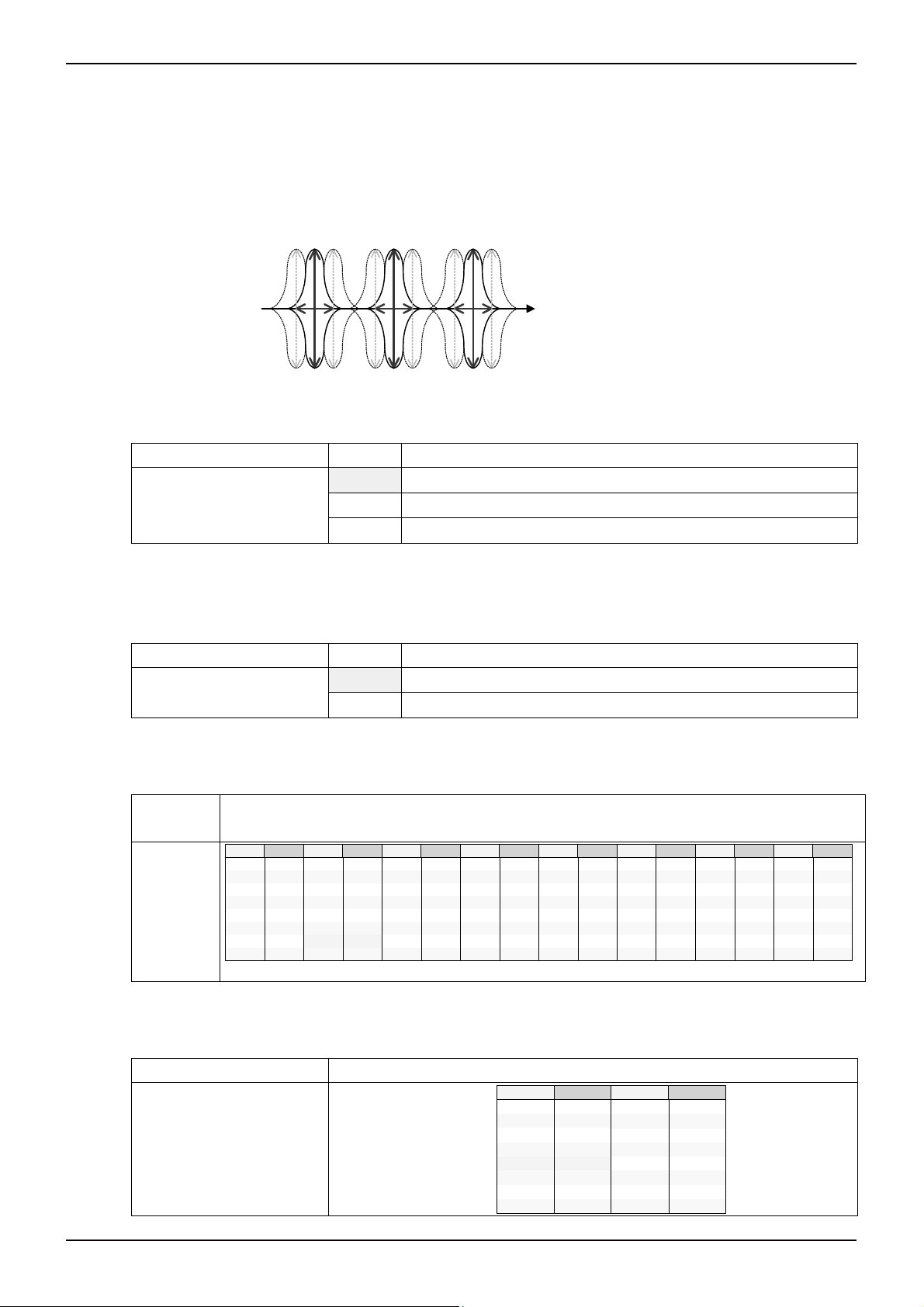
44--1100.. SSuurrrroouunndd ((MMaattrriixx SSuurrrroouunndd 33DD))
Rch Rch
It realizes the Surround with little feeling of fatigue even after wide seat spot and long-time watching & listening to. It
reproduces the feeling of broadening of the natural sounds in medium & high bands and realizes the sound field that do no
damage to the feeling of locating of the vocal.
If loop is used, then the number of stages of phase shifter can be increased in a pseudo way.
Lch
Loop
+
Lch
+
+
L-R
-
+
+
PHASE
SHIFTER
EFFECT
GAIN
LPF
-
www.rohm.com
© 2012 ROHM Co., Ltd. All rights reserved.
Rch
27/54
+
Rch
2012.03 - Rev.

BU9409FV
A
ON/OFF of Surround function
Default = 0
Select Address Value Operational explanation
&h70 [ 7 ]
Setting of using the LOOP
Default = 0
Select Address Value Operational explanation
&h70 [ 5 ]
Setting of Surround gain
Default = Fh
Select Address Operational explanation
&h70 [ 3:0 ]
Technical Note
0 Turning the Surround effect OFF
1 Turning the Surround effect ON
0 Not using of LOOP
1 Using of LOOP
Command
00dB
1
2
3
4
5
6
7
Gain
-1dB
-2dB
-3dB
-4dB
-5dB
-6dB
-7dB
Command
8
9
A
B
C
D
E
F
Gain
-8dB
-9dB
-10dB
-11dB
-12dB
-13dB
-14dB
-15dB
www.rohm.com
© 2012 ROHM Co., Ltd. All rights reserved.
28/54
2012.03 - Rev.

BU9409FV
A
V
d
2
2
P
44--1111.. P
BBaassss ((PPeerrffeecctt PPuurree BBaassss:: DDeeeepp BBaassss EEqquuaalliizzeerr))
Technical Note
It is the deep bass equalizer making it possible that even thin-screen TV, by which the enclosure of speaker is restricted,
can reproduce the real sound close to powerful deep bass & original sound.
Solid & clear deep bass with little feeling of distortion is realized. Even boosting of bass does not interfere with vocal band,
therefore rich and natural deep band is realized.
Gain
ocal ban
P2Bass gain
P2Bassゲイン
ボーカル帯域
f
LPF Cutoff frequency
ON/OFF
2
Bass function
of P
Default = 0
HPF Cutoff frequency
HPFカットオフ周波数
LPFカットオフ周波数
Select Address Value Operational explanation
&h73 [ 7 ]
0 Not using of P2Bass function
1 Using of P2Bass function
2
Setting of P
Bass smooth transition time
Default = 0
Select Address Value Operational explanation
&h73 [ 3:2 ]
0 21.4ms
1 10.7ms
2 5.4ms
3 2.7ms
2
Bass smooth transition control
P
Default = 0
Select Address Value Operational explanation
&h77 [ 1:0 ]
0 P2Bass smooth transition stop
1 Setting of the values into Coefficient RAM for P2Bass smooth transition
2 P2Bass smooth transition start
2
What is necessary is the time of waiting, which is more than the time selected by the setting of P
2
time, from the time the P
Please make sure to perform the P
Bass smooth transition start(&h77[1:0] = “2”) is executed until the following command is sent.
2
Bass smooth transition stop(&h77[1:0] = “0”) after the smooth transition is completed.
Bass smooth transition
www.rohm.com
© 2012 ROHM Co., Ltd. All rights reserved.
29/54
2012.03 - Rev.

BU9409FV
A
Setting of P2Bass deep bass gain
Default = 00h
Select Address Operational explanation
&h74 [ 7:4 ]
Command Gain
0 0dB
1
2
3
4
5
6
7
+1dB
+2dB
+3dB
+4dB
+5dB
+6dB
+7dB
Command
8
9
A
B
C
D
E
F
2
Setting of P
Bass HPF cutoff frequency
Default = 0
Select Address Value Operational explanation
&h74 [ 3:2 ]
0 60Hz
1 80Hz
2 100Hz
3 120Hz
2
Setting of P
Bass LPF cutoff frequency
Default = 0
Select Address Value Operational explanation
&h74 [ 1:0 ]
0 120Hz
1 160Hz
2 200Hz
3 240Hz
ON/OFF of pseudo bass function
It can contribute to bass emphasis effect caused by pseudo bass. And it can also be used independently.
Default = 0
Select Address Value Operational explanation
&h72 [ 7 ]
0 Not using of pseudo bass function
1 Using of pseudo bass function
Setting of pseudo bass gain
Default = 00h
Select Address Operational explanation
&h72 [ 6:4 ]
Command Gain
0 -4dB
1 -2dB
2
3
0dB
+2dB
Command
4
5
6
7
Technical Note
Gain
+8dB
+9dB
+10dB
+11dB
+12dB
+13dB
+14dB
+15dB
Gain
+4dB
+6dB
+8dB
+10dB
www.rohm.com
© 2012 ROHM Co., Ltd. All rights reserved.
30/54
2012.03 - Rev.

BU9409FV
A
2
2
P
44--1122.. P
TTrreebbllee ((PPeerrffeecctt PPuurree TTrreebbllee::MMeeddiiuumm・・HHiigghh--bbaanndd eeqquuaalliizzeerr))
Technical Note
It realizes good Clearness, sound stretch, and clear-cut manner.
It realizes such an effect that the sound is raised and can be heard when speaker is located on the underside of a device.
2
ON/OFF of P
Treble function
Default = 0
Select Address Value Operational explanation
&h75 [ 7 ]
0 Not using of P2Treble function
1 Using of P2Treble function
2
Setting of P
Treble smooth transition time
Default = 0
Select Address Value Operational explanation
&h75 [ 3:2 ]
0 21.4ms
1 10.7ms
2 5.4ms
3 2.7ms
2
Treble smooth transition control
P
Default = 0
Select Address Value Operational explanation
&h78 [ 1:0 ]
0 P2Treble smooth transition stop
1
Setting of the values into Coefficient RAM for P
transition
2
Treble smooth
2 P2Treble smooth transitionStart
2
What is necessary is the time of waiting, which is more than the time selected by the setting of P
2
time, from the time the P
Please make sure to perform the P
Treble smooth transition start(&h78[1:0] = “2”) is executed until the following command is sent.
2
Treble smooth transition stop(&h78[1:0] = “0”) after the smooth transition is completed.
Treble smooth transition
2
Setting of P
Treble medium・high-band gain
Default = 0h
Select Address Operational explanation
&h76 [ 7:4 ]
Command Gain
0 0dB
1
2
3
4
5
6
7
+1dB
+2dB
+3dB
+4dB
+5dB
+6dB
+7dB
Command
8
9
A
B
C
D
E
F
Gain
+8dB
+9dB
+10dB
+11dB
+12dB
+13dB
+14dB
+15dB
www.rohm.com
© 2012 ROHM Co., Ltd. All rights reserved.
31/54
2012.03 - Rev.

BU9409FV
A
Technical Note
44--1133.. SSccaalleerr 22
Scaler adjusts the gain in order to prevent the overflow in DSP.
Adjustable range is +24dB to -103dB and can be set by the step of 0.5dB.
Scaler 2 does not incorporate the smooth transition function.
Default = 30h
Select Address Operational explanation
&h25 [ 7:0 ]
Command Gain
00
01 +23.5dB
30
31
32
……
FE
FF
+24dB
0dB
-0.5dB
-1dB
……
-103dB
-∞
44--1144.. 77 bbaanndd・・ppaarraammeettrriicc eeqquuaalliizzeerr
77--bbaanndd ppaarraammeettrriicc eeqquuaalliizzeerr
an use Peaking filter, Low-shelf filter or high-shelf filter.
c
The setting is converted, in the IC, into digital filter’s coefficients (b0, b1, b2, a1, a2)by selecting the F,Q and Gain, and
transmitted to coefficient RAM. There is no smooth transition function.
Band1 Band2 Band3 Band4 Band5 Band6 Band7
f
Level
±18dB
(0.5dB step)
63 160 400 1k 2.5k 6.3k 16k (Hz)
Selection of filter types
Default = 0
Select Address Value Operational explanation
bit[ 7:6 ]
It sets to all band
0 Peaking filter
1 Low-shelf filter
2 High-shelf filter
Setting of the Start of transmitting to coefficient RAM
It is transmitted to direct coefficient RAM.
Default = 0
Select Address Value Operational explanation
bit [ 0 ]
It sets to all band
0 Coefficient transmission stop
1 Coefficient transmission start
www.rohm.com
© 2012 ROHM Co., Ltd. All rights reserved.
32/54
2012.03 - Rev.

BU9409FV
A
Selection of frequency(F0)
Default = 0Eh
Select
Operational explanation
Address
bit [ 5:0 ]
It sets to all
band
Command
00
01
02
03
04
05
06
07
Frequency
20Hz
22Hz
25Hz
28Hz
32Hz
35Hz
40Hz
45Hz
Command
08
09
0A
0B
0C
0D
0E
0F
Frequency
50Hz
56Hz
63Hz
70Hz
80Hz
90Hz
100Hz
110Hz
Command
10
11
12
13
14
15
16
17
Frequency
125Hz
140Hz
160Hz
180Hz
200Hz
220Hz
250Hz
280Hz
Command
18
19
1A
1B
1C
1D
1E
1F
Frequency
315Hz
350Hz
400Hz
450Hz
500Hz
560Hz
630Hz
700Hz
Command
20
21
22
23
24
25
26
27
Selection of quality factor(Q)
Default = 4h
Select Address Operational explanation
bit [ 3:0 ]
It sets to every band
Command
Quality factor
0
1
2
3
4
5
6
7
0.33
0.43
0.56
0.75
1.0
1.2
1.5
1.8
Selection of Gain
Default = 40h
Select Address Operational explanation
bit [ 6:0 ]
It sets to every band
Command Gain
1C -18dB
…
3E -1dB
3F
40
41
…
64
If the coefficient of b0, b1, b2, a1, and a2 exceeds ±4, it may not operate normally.
The Select Address of each band is shown in the table below:
Band1 Band2 Band3 Band4 Band5 Band6 Band7
Selection of filter type bit [ 7:6 ]
Setting of the Start of transmitting to
&h50h &h54h &h58h &h5Ch &h60h &h64h &h68h
coefficient RAM bit [ 0 ]
F(frequency)selection bit [ 5:0 ] &h51h &h55h &h59h &h5Dh &h61h &h65h &h69h
Q(Quality Factor) selection bit [ 3:0 ] &h52h &h56h &h5Ah &h5Eh &h62h &h66h &h6Ah
Gain selection bit [ 6:0 ] &h53h &h57h &h5Bh &h5Fh &h63h &h67h &h6Bh
Frequency
800Hz
900Hz
1kHz
1.1kHz
1.25kHz
1.4kHz
1.6kHz
1.8kHz
Command
Command
8
9
A
B
C
D
E
F
-0.5dB
+0.5dB
+1dB42
+18dB
28
29
2A
2B
2C
2D
2E
2F
…
0dB
…
Frequency
2kHz
2.2kHz
2.5kHz
2.8kHz
3.15kHz
3.5kHz
4kHz
4.5kHz
Quality factor
2.2
2.7
3.3
3.9
4.7
5.6
6.8
8.2
Technical Note
Frequency
Command
5kHz
30
31
5.6kHz
6.3kHz
32
33
7kHz
8kHz
34
35
9kHz
10kHz
36
37
11kHz
Command
38
39
3A
3B
3C
3D
3E
3F
Frequency
12.5kHz
14kHz
16kHz
18kHz
20kHz
-
-
-
www.rohm.com
© 2012 ROHM Co., Ltd. All rights reserved.
33/54
2012.03 - Rev.

BU9409FV
A
Technical Note
44--1155.. MMaaiinn oouuttppuutt EEVVRR ((EElleeccttrroonniicc vvoolluummee))
Volume is from+24dB to -103dB, and can be selected by the step of 0.5dB.
At the time of switching of Volume, smooth transition is performed. The smooth transition time takes about 22ms in the case
of transiting from 0dB. (Fixed)
Setting of Volume
Default = FFh
Select Address Operational explanation
&h26 [ 7:0 ]
Command Gain
00
01 +23.5dB
30
31
32
……
FE
FF
+24dB
0dB
-0.5dB
-1dB
……
-103dB
-∞
44--1166.. MMaaiinn oouuttppuutt bbaallaannccee
Balance can be attenuated, by the step width of 1dB, from the Volume setting value. At the time of switching, smooth
transition is performed. At the time of switching of Balance, smooth transition is performed. The smooth transition time takes
about 22ms. (Fixed)
Setting of L/R Balance
Default = 80h
Select Address Operational explanation
&h27 [ 7:0 ]
Command Lch
00
01
…
7F
80
81
…
FE
-126dB
0dB
0dB
…
0dB
0dB
-1dB
…
Rch
-∞
-126dB
…
-1dB0dB7E
0dB
0dB
0dB
…
0dB
0dB-∞FF
44--1177.. MMaaiinn oouuttppuutt ppoossttssccaalleerr
It performs the level adjustment when the data calculated in the 32-bit-width DSP is outputted in the form of 24bitwidth.
Adjustable range is from +24dB to -103dB and can be set by the step of 0.5dB.
There is no smooth transition function in Postscaler.
Default = 30h
Select Address Operational explanation
&h28 [ 7:0 ]
Command Gain
00
01 +23.5dB
30
31
32
……
FE
FF
+24dB
0dB
-0.5dB
-1dB
……
-103dB
-∞
www.rohm.com
© 2012 ROHM Co., Ltd. All rights reserved.
34/54
2012.03 - Rev.

BU9409FV
A
Technical Note
44--1188.. MMaaiinn oouuttppuutt cclliippppeerr
When measuring the rated output (practical maximum output), it is measured where the total distortion rate (THD+N) is
10%. Clipping with any output amplitude is possible by using of clipper function, for example, the rated output of 10W or 5W
can be obtained by using an amplifier with 15W output.
Please set the &h27[7] at “H” when using of clipper function.
Default = 0
Select Address Value Operational explanation
Clip level is set in the form of higher-order 8 bit&h2A[7:0] and lower-order 8 bit&h2B[7:0].
&h29 [ 7 ]
Clip Level
0 Not using clipper function
1 Using clipper function
23 22 21 20 19 18 17 16 15 14 13 12 11 10 9 8 7 6 5 4 3 2 1 0
10111 1111111111111111111
01000 0000000000000000000
0
1
l becomes narrow if the setting value is reduced.
Negative clip level is set in such a way that it is the inversion data of positive clip level.
44--1199.. SSeelleeccttiioonn ooff ssuubb iinnppuutt ddaattaa
Selection of Sub input (Sub woofer processing etc.).
The Sub woofer output interlocked with P2Bass’s gain setting is possible by inputting the data that after P2Bass processing.
In addition, in BU9409FV, the data can be inputted from SP conversion2.
Default = 0
clip_level[15:0]
~clip_level[15:0]
Select Address Value Operational explanation
&h2F [ 1:0 ]
0 Inputting of data that are after scaler 1
1 Inputting of data that are after P2Bass processing
2 Inputting of data from SP conversion2
0000000
1111111
Maximum value
Minimum value
A positive clip level
A negative clip level
The
clip
leve
www.rohm.com
© 2012 ROHM Co., Ltd. All rights reserved.
35/54
2012.03 - Rev.

BU9409FV
A
Technical Note
44--2200.. SSuubb oouuttppuutt cchhaannnneell mmiixxeerr
Mixing setting of sound of the left channel and the right channel of the digital signal for sub output which is input into sound
DSP is done. The monaural conversion of the stereo signal is done here.
The data which is input into Lch of Sub output signal processing is mixed.
Default = 0
Select Address Value Operating explanation
&h22 [ 3:2 ]
The data which is input into Rch of Sub output signal processing is mixed.
Default = 0
Select Address Value Operating explanation
&h22 [ 1:0 ]
44--2211.. LLPPFF ffoorr ssuubb wwooooffeerr oouuttppuutt
It is the crossover filter (LPF) for sub woofer output.
LPF function ON/OFF.
Default = 0
Select Address Value Operating explanation
&h7A [ 7 ]
Setting of the cut off frequency (Fc) of LPF
Default = 0h
Select Address Operating explanation
&h7A [ 6:4 ]
0 Inputting the Lch data
1 Inputting the data of (Lch + Rch) / 2
2 Inputting the data of (Lch + Rch) / 2
3 Inputting the Rch data
0 Inputting the Rch data
1 Inputting the data of (Lch + Rch) / 2
2 Inputting the data of (Lch + Rch) / 2
3 Inputting the Lch data
0 LPF function is not used
1 LPF function is used
Command Fc
0
1
2
3
60Hz
80Hz
100Hz
120Hz
Command
4
5
6
7
Fc
160Hz
200Hz
240Hz
280Hz
www.rohm.com
© 2012 ROHM Co., Ltd. All rights reserved.
36/54
2012.03 - Rev.
BU9409FV
A
Technical Note
44--2222.. SSuubb oouuttppuutt 33 bbaanndd
Parametric Equalizer
The peaking filter or the low shelf filter or the high shelf filter can be used by the parametric equalizer of 3 bands. By the fact
that F, Q and Gain are selected, it converts the setting to the coefficient (b0, b1, b2, a1 and a2) of the digital filter inside IC,
and transfers it to the coefficient RAM. There is no smooth transition function.
Band1 Band2 Band3
f
Level
±18dB
(0.5dB step)
Selection of filter type
Default = 0
63 80 100 (Hz)
Select Address Value Operating explanation
bit[ 7:6 ]
It sets to all band
0 Peaking filter
1 Low shelf filter
2 High shelf filter
Transfer start setting to coefficient RAM.
It transfers directly to coefficient RAM.
Default = 0
Select Address Value Operating explanation
bit [ 0 ]
It sets to all band
0 Coefficient transmission stop
1 Coefficient transmission start
Selection of frequency (F
Default = 0Eh
Select
)
0
Operating explanation
Address
bit [ 5:0 ]
It sets to all
band
Command
00
01
02
03
04
05
06
07
Frequency
20Hz
22Hz
25Hz
28Hz
32Hz
35Hz
40Hz
45Hz
Command
08
09
0A
0B
0C
0D
0E
0F
Frequency
50Hz
56Hz
63Hz
70Hz
80Hz
90Hz
100Hz
110Hz
Command
10
11
12
13
14
15
16
17
Frequency
125Hz
140Hz
160Hz
180Hz
200Hz
220Hz
250Hz
280Hz
Command
18
19
1A
1B
1C
1D
1E
1F
Frequency
315Hz
350Hz
400Hz
450Hz
500Hz
560Hz
630Hz
700Hz
Command
20
21
22
23
24
25
26
27
Frequency
800Hz
900Hz
1kHz
1.1kHz
1.25kHz
1.4kHz
1.6kHz
1.8kHz
Command
28
29
2A
2B
2C
2D
2E
2F
Frequency
2kHz
2.2kHz
2.5kHz
2.8kHz
3.15kHz
3.5kHz
4kHz
4.5kHz
Command
30
31
32
33
34
35
36
37
Frequency
5kHz
5.6kHz
6.3kHz
7kHz
8kHz
9kHz
10kHz
11kHz
Command
38
39
3A
3B
3C
3D
3E
3F
Selection of quality factor (Q)
Default = 4h
Select Address Operating explanation
bit [ 3:0 ]
It sets to all band
Command
Quality factor
0
1
2
3
4
5
6
7
Command
0.33
0.43
0.56
0.75
1.0
1.2
1.5
1.8
Quality factor
8
9
A
B
C
D
E
F
2.2
2.7
3.3
3.9
4.7
5.6
6.8
8.2
Frequency
12.5kHz
14kHz
16kHz
18kHz
20kHz
-
-
-
www.rohm.com
© 2012 ROHM Co., Ltd. All rights reserved.
37/54
2012.03 - Rev.

BU9409FV
A
Selection of Gain
Default = 40h
Select Address Operating explanation
bit [ 6:0 ]
It sets to all band
Command Gain
1C -18dB
…
3E -1dB
3F
40
41
…
…
-0.5dB
0dB
+0.5dB
+1dB42
…
Technical Note
64
+18dB
If the coefficient of b0, b1, b2, a1, and a2 exceeds ±4, it may not operate normally.
Select Address of every band is as in chart below
Band1 Band2 Band3
Selection of filter type bit [ 7:6 ]
&h80h &h84h &h88h
Transfer start setting to coefficient RAM
bit [ 0 ]
F (frequency) selection bit [ 5:0 ] &h81h &h85h &h89h
Q (quality factor) selection bit [ 3:0 ] &h82h &h86h &h8Ah
Gain selection bit [ 6:0 ] &h83h &h87h &h8Bh
44--2233.. SSuubb oouuttppuutt EEVVRR ((eelleeccttrroonniicc vvoolluummee))
The volume for sub output can select with 0.5dB step from +24dB to -103dB.
When changing volume, smooth transition is done. Smooth transition duration is required approximately 22ms when it is
from 0dB. (Fixed)
Volume setting
Default = FFh
Select Address Operating explanation
&h2C [ 7:0 ]
Command Gain
00
01 +23.5dB
30
31
32
……
FE
FF
+24dB
0dB
-0.5dB
-1dB
……
-103dB
-∞
www.rohm.com
© 2012 ROHM Co., Ltd. All rights reserved.
38/54
2012.03 - Rev.

BU9409FV
A
Technical Note
44--2244.. SSuubb oouuttppuutt bbaallaannccee
As for sub output balance, it is possible to be attenuated at 1dB step width from volume setting value. When changing,
smooth transition is done.
When changing balance, smooth transition is done. Smooth transition duration is required approximately 22ms. (Fixed)
L/R Balance setting
Default = 80h
Select Address Operating explanation
&h2D [ 7:0 ]
Command Lch
00
01
…
7F
80
81
…
FE
0dB
0dB
…
0dB
0dB
-1dB
…
-126dB
Rch
-∞
-126dB
…
-1dB0dB7E
0dB
0dB
0dB
…
0dB
0dB-∞FF
44--2255.. SSuubb oouuttppuutt ppoosstt ssccaalleerr
The occasion when the data which is calculated with DSP of 32bit width is output at 24bit width, level adjustment is done.
The adjustment range can be set with 0.5dB step from +24dB to -103dB.
There is no smooth transition function in the sub output post scaler.
Default = 30h
Select Address Operating explanation
&h2E [ 7:0 ]
Command Gain
00
01 +23.5dB
30
31
32
……
FE
FF
+24dB
0dB
-0.5dB
-1dB
……
-103dB
-∞
www.rohm.com
© 2012 ROHM Co., Ltd. All rights reserved.
39/54
2012.03 - Rev.

BU9409FV
A
Technical Note
44--2266.. SSuubb oouuttppuutt cclliippppeerr
The case when rated output (practical maximum output) of the television is measured, total harmonic distortion + noise
(THD+N) measures at the place of 10%. It can obtain the rated output of 10W and 5W for example making use of the
amplifier of 15W output, because it is possible to clip with optional output amplitude by using the clipper function.
Please designate &h30 [7] as” H when using sub output clipper
function.
Default = 0
As for clip level, it sets with superior 8 bits &h31 [7: 0] and subordinate 8 bits &h32 [7: 0].
Clip Level
Select Address Value Operating explanation
&h30 [ 7 ]
0 Clipper function is not used
1 Clipper function is used
23 22 21 20 19 18 17 16 15 14 13 12 11 10 9 8 7 6 5 4 3 2 1 0
10111 1111111111111111111
01000 0000000000000000000
0
1
g value is made small, clip level becomes narrow.
As for negative clip level, the reversal data of positive clip level is set.
clip_level[15:0]
~clip_level[15:0]
0000000
1111111
Maximum value
Minimum value
A positive clip level
A negative clip level
When
settin
www.rohm.com
© 2012 ROHM Co., Ltd. All rights reserved.
40/54
2012.03 - Rev.

BU9409FV
A
Technical Note
44--2277.. DDiirreecctt sseettttiinngg ffiivvee ccooeeffffiicciieenntt ooff bb00,, bb11,, bb22,, aa11 aanndd aa22 ooff BBii--qquuaadd FFiilltteerr
7 bands Parametric Equalizer of main output and of 3 bands Parametric Equalizer of sub output have used the secondary
IIR type digital filter (Bi-quad Filter).
It is possible to set five coefficient 24 bit of b0, b1, b2, a1 and a2 of Bi-quad Filter (-4~+4) directly from an external.
When this function is used, it can do the filter type and frequency setting, Q value (quality factor) setting and gain setting
other than Peaking, Low-Shelf and High-Shelf unrestrictedly.
(Note) five coefficient have the necessity to make below the ±4, there is no read-out function of setting value and an
automatic renewal function of coefficient RAM.
Register for the coefficient transfer of 24bit
Before transferring into coefficient RAM in a lumping, the data is housed in the register for coefficient transfer from the
micro-computer.
Default = 00h
Select Address Operating explanation
&h8D [ 7:0] bit[23:16] which transfers 24 bit coefficient
&h8E [ 7:0] bit[15:8] which transfers 24 bit coefficient
&h8F [ 7:0] bit[7:0] which transfers 24 bit coefficient
It starts to transmit the coefficient of 24bit into coefficient RAM
Default = 0
Select Address Value Operating explanation
&h8C [ 7 ]
0 Coefficient transmission stop
1 Coefficient transmission start
Coefficient number appointment of coefficient RAM
Default = 00h
Select Address Operating explanation
&h8C [ 6:0] Coefficient number appointment of coefficient RAM
Appointment of coefficient number other than 14H↔45H is prohibition
Main output 7Band Parametric EQ
-1
Z
-1
Z
Coefficient
:number
14
H.
b0
+
+ +
15
16
H.
17
H.
BAND1 (Main)
H
a1b1
+ +
18
H
a2b2
Sub output 3Band Parametric EQ
Coefficient
37
H.
b0
-1
Z
38
H.
-1
Z
39
H.
Coefficient
19
b0
-1
-1
Z
Z
1A
-1
-1
Z
Z
1B
:number
+
+ +
+ +
BAND1 (Sub) BAND2 (Sub) BAND3 (Sub)
Coefficient
:number
H.
+ +
-1
Z
1C
+ +
-1
Z
-1
Z
1D
Z
Z
H
a1b1
Z
H
a2b2
Coefficient
3C
b0
-1
3D
-1
3E
-1
H.
H.
BAND2 (Main) BAND3 (Main) BAND4 (Main) BAND5 (Main) BAND6 (Main) BAND7 (Main)
3A
H
a1b1
3B
H
a2b2
:number
1E
H.
b0
+ +
-1
Z
1F
H.
+ +
-1
Z
20
H.
:number
H.
+ +
3F
40
H
a1b1
H
a2b2
H.
H.
+ +
21
a1b1
22
H
a2b2
-1
Z
-1
Z
Coefficient
:number
23
H.
b0
+ +
-1
-1
Z
Z
Z
-1
Z
Z
-1
Z
Coefficient
41
b0
-1
42
-1
43
24
H.
25
H.
:number
H.
H.
H.
H
26
+ +
27
+
44
+ +
45
Coefficient
:number
28
H.
b0
+ +
-1
-1
Z
Z
H
a1b1
H
a2b2
29
H.
-1
-1
Z
Z
2A
H.
-1
Z
H
a1b1
-1
Z
H
a2b2
+ +
2B
a1b1
2C
a2b2
Coefficient
:number
2D
H.
b0
+ +
-1
-1
Z
Z
H
H
2E
H.
-1
-1
Z
Z
2F
H.
+ +
30
a1b1
31
a2b2
Coefficient
:number
32
H.
b0
-1
-1
Z
Z
H
H
33
H.
+ +
-1
-1
Z
Z
34
H.
+
-1
Z
35
H
a1b1
-1
Z
36
H
a2b2
www.rohm.com
© 2012 ROHM Co., Ltd. All rights reserved.
41/54
2012.03 - Rev.

BU9409FV
A
Technical Note
44--2288.. AAbboouutt tthhee aauuttoommaattiicc rreenneewwaall ooff ffiivvee ccooeeffffiicciieennttss ooff bb00,, bb11,, bb22,, aa11 aanndd aa22 ooff BBii--qquuaadd FFiilltteerr
BASS, MIDDLE, TREBLE, main output 7 bands Parametric Equalizer and sub output 3 band Parametric Equalizer have
used coefficient RAM. As for this coefficient RAM, because direct access is not possible from the micro-computer, it cannot
refresh the register efficiently.
here is an automatic renewal function of coefficient RAM in this DSP, the automatic write-in renewal of coefficient RAM is
T
possible by using this function. However when 4-26 「the function of direct setting a coefficient RAM」 is utilized, it is not
possible to utilize automatic write-in renewal.
Selection of using the automatic write-in renewal function
Default = 0
Select Address Value Operating explanation
&h6D [ 0 ]
The separate setting of Filter of automatic write-in renewal function
Default = 00h
Select Address Filter Operating explanation
&h6E [ 0 ] BASS 0:Automatic renewal function OFF
&h6E [ 1 ] MIDDLE 0:Automatic renewal function OFF
&h6E [ 2 ] TREBLE 0:Automatic renewal function OFF
&h6E [ 4 ] Sub BAND1 0:Automatic renewal function OFF
&h6E [ 5 ] Sub BAND2 0:Automatic renewal function OFF
&h6E [ 6 ] Sub BAND3 0:Automatic renewal function OFF
&h6F [ 0 ] Main MAND1 0:Automatic renewal function OFF
&h6F [ 1 ] Main MAND2 0:Automatic renewal function OFF
&h6F [ 2 ] Main MAND3 0:Automatic renewal function OFF
&h6F [ 3 ] Main MAND4 0:Automatic renewal function OFF
&h6F [ 4 ] Main MAND5 0:Automatic renewal function OFF
&h6F [ 5 ] Main MAND6 0:Automatic renewal function OFF
&h6F [ 6 ] Main MAND7 0:Automatic renewal function OFF
0 Automatic write-in renewal function is used
1 Automatic write-in renewal function is not used
1:Automatic renewal function ON
1:Automatic renewal function ON
1:Automatic renewal function ON
1:Automatic renewal function ON
1:Automatic renewal function ON
1:Automatic renewal function ON
1:Automatic renewal function ON
1:Automatic renewal function ON
1:Automatic renewal function ON
1:Automatic renewal function ON
1:Automatic renewal function ON
1:Automatic renewal function ON
1:Automatic renewal function ON
www.rohm.com
© 2012 ROHM Co., Ltd. All rights reserved.
42/54
2012.03 - Rev.

BU9409FV
A
Technical Note
5. P-S conversion 1 ,P-S conversion 2
Two parallel serial conversion circuits are built in BU9409FV. (P-S conversion 1, P-S conversion 2)
P-S conversion 1 convert the Main output of DSP from SDATAO1, LRCKO, and BCKO (34,35,36pin) into three line serial
data and output the data.
P-S conversion 2 convert the sub output of DSP from SDATAO1, LRCKO, and BCKO (33,35,36pin) into three line serial data
and output the data.
Output format has the IIS mode, left-align mode, and right-align mode. 16 each bit, 20bit, and 24bit output can also be
selected. The figure below shows the timing chart of each transmission mode.
IIS mode
IIS方式
LRCKO
1 2 3 4 5 6 7 8 9 10 11 12 13 14 15 16 17 18 19 20 21 22 23 24 25 26 27 28 29 30 31 32 1 2 3 4 5 6 7 8 9 10 11 12 13 14 15 16 17 18 19 20 21 22 23 24 25 26 27 28 29 30 31 32
BCKO
MSB LSB
S
DATAO
16bit
MSB LSB
S
16bit
20bit
24bit
20bit
24bit
left-align mode
左詰方式
LRCKO
1 2 3 4 5 6 7 8 9 10 11 12 13 14 15 16 17 18 19 20 21 22 23 24 25 26 27 28 29 30 31 32 1 2 3 4 5 6 7 8 9 10 11 12 13 14 15 16 17 18 19 20 21 22 23 24 25 26 27 28 29 30 31 32
BCKO
MSB L SB
S
DATAO
16bit
20bit
24bit
MSB L SB
S
16bit
20bit
24bit
right-align mode
右詰方式
LRCKO
1 2 3 4 5 6 7 8 9 10 11 12 13 14 15 16 17 18 19 20 21 22 23 24 25 26 27 28 29 30 31 32 1 2 3 4 5 6 7 8 9 10 11 12 13 14 15 16 17 18 19 20 21 22 23 24 25 26 27 28 29 30 31 32
BCKO
DATAO
MSB LSB
S
16bit
20bit
24bit
MSB LSB
S
16bit
20bit
24bit
p
55--11.. FFoorrmmaatt sseettttiinngg ooff tthhrreeee lliinnee sseerriiaall oouuttp
Default =
0
uutt
Select Address Value Operating Description
P-S conversion 1 &h0D [ 3:2 ]
P-S conversion 2
& h0E [ 3:2 ]
0 IIS mode
1 left-align mode
2 right-align mode
55--22.. SSeettttiinngg ddaattaa bbiitt wwiiddtthh ooff tthhrreeee lliinnee sseerriiaall oouuttppuutt
Default =
0
Select Address Value Operating Description
P-S conversion 1 &h0D [ 1:0 ]
P-S conversion 2
& h0E [ 1:0 ]
0 16 bit
1 20 bit
2 24 bit
www.rohm.com
© 2012 ROHM Co., Ltd. All rights reserved.
43/54
2012.03 - Rev.

BU9409FV
A
6. Mute function by command
Mute function by command is provided in BU9409FV.
It's possible to mute DSP's main and sub digital output by setting to &hFD [ 4 ] = 1h and MUTEX_DAC terminal and a
MUTEX_SP terminal both to L.
Setting the transition time of smooth mute
Mute the Main and Sub output of DSP.
Select the transition time of entering from 0dB to mute state.
Smooth transition time when releasing mute is about 22ms(fixed) .
Default = 0
Select Address Value Operating Description
&h10 [ 1:0 ]
0 Don’t use mute function.
1 10.8ms
2 5.4ms
3 2.7ms
Technical Note
7. Clock halt function of DSP part
Clock halt function of DSP part with terminal MUTEX_DAC and MUTEX_SP is provided in BU9409FV.
Clock halt function’s setting
Default = 0
Select Address Value Operating Description
&hA9 [ 7 ]
When setting on using the clock halt function, then set the MUTEX_DAC and MUTEX_SP terminal on L ,the clock of DSP
part will be halted. If clock is halted, command can’t be sent and received in a part of the block. If &hA9 [ 7 ] is input from
MCLK into clock, command can be sent and received even on the clock halt condition.
When MUTEX_DAC or MUTEX_SP terminal is on H, the clock halt will be released.
Power consumption decreases in the clock halt condition.
0 Don’t use the clock halt function
1 Use the clock halt function
www.rohm.com
© 2012 ROHM Co., Ltd. All rights reserved.
44/54
2012.03 - Rev.

BU9409FV
A
8. Command sent after releasing reset
Please send the following command after releasing reset including power supply on.
0. Power supply turning on
↓
○ Please input the clock from the outside. When the clock is not input, reset can't normally be done.
↓
1. Reset release (RESETB="H")
↓
2. &hA0[7:0] = C2h :Set PLLA.
↓
3. &hF3[5:0] = 10h :Set the dividing frequency ratio of MCLK. Please do as follows to set a value by fs of
MCLK.
(MCLK:512fs=10h、256fs=08h、128fs=04h)
↓
4. &hF5[3:0] = 1h:Set the dividing frequency ratio of PLL.
↓
5. &hF6[5:0] = 23h:Set the phase match of PLL.
↓
6. &hF1[4] = 0 :Turn on the analog input.
↓
7. &h08[5:4] = 1h :Select the system clock.
↓
8. &hA7[7:0] = F4h:Synchronous detection condition setting 1 for PLLA is initialized.
↓
9. &hA8[7:0] = 33h:Synchronous detection condition setting 2 for PLLA is initialized.
↓
10. &hA9[3:0] = 3h:Synchronous detection condition setting 3 for PLLA is initialized.
↓
11. &hA9[5:4] = 2h or 1h or 0h :Set MCLK.
(Set in “2h”While MCLK is 512fs, set in “1h”While MCLK is 256fs, set in “0h”While MCLK is 128fs.)
↓
○ It is about 20ms weight until PLL is steady.
↓
10. &h01[5:4] = 0h :Turn off the RAM Clear.
↓
11. Other register setting
&h26[7:0] = **h :Release the mute of the Main output volume(30h=0dB).
&h2C[7:0] = **h :Release the mute of the Sub output volume(30h=0dB).
Technical Note
www.rohm.com
© 2012 ROHM Co., Ltd. All rights reserved.
45/54
2012.03 - Rev.

BU9409FV
A
Technical Note
9. About frequency setting such as tone control and parametric equalizer
Because the sampling rate converter is not built into BU9409FV, the calculation clock of DSP is changed according to the
input sampling rate of I2S.
Because sampling rate describes the frequency on the assumption of 48kHz in this function specification, conversion is
needed in case of sampling frequency of 44.1kHz and 32kHz.
Please refer to the table below for F0 setting of tone control (Bass, Middle, Treble) and parametric equalizer.
F0 (fs=48kHz)
Command
00
01
02
03
04
05
06
07
Frequency
20Hz
22Hz
25Hz
28Hz
32Hz
35Hz
40Hz
45Hz
Command
08
09
0A
0B
0C
0D
0E
0F
Frequency
50Hz
56Hz
63Hz
70Hz
80Hz
90Hz
100Hz
110Hz
Command
10
11
12
13
14
15
16
17
Frequency
125Hz
140Hz
160Hz
180Hz
200Hz
220Hz
250Hz
280Hz
Command
18
19
1A
1B
1C
1D
1E
1F
Frequency
315Hz
350Hz
400Hz
450Hz
500Hz
560Hz
630Hz
700Hz
Command
20
21
22
23
24
25
26
27
Frequency
800Hz
900Hz
1kHz
1.1kHz
1.25kHz
1.4kHz
1.6kHz
1.8kHz
Command
28
29
2A
2B
2C
2D
2E
2F
Frequency
2kHz
2.2kHz
2.5kHz
2.8kHz
3.15kHz
3.5kHz
4kHz
4.5kHz
Command
30
31
32
33
34
35
36
37
Frequency
5kHz
5.6kHz
6.3kHz
7kHz
8kHz
9kHz
10kHz
11kHz
Command
38
39
3A
3B
3C
3D
3E
3F
F0 (fs=44.1kHz)
Command
00
01
02
03
04
05
06
07
Frequency
18Hz
20Hz
23Hz
26Hz
29Hz
32Hz
37Hz
41Hz
Command
08
09
0A
0B
0C
0D
0E
0F
Frequency
46Hz
51Hz
58Hz
64Hz
74Hz
83Hz
92Hz
101Hz
Command
10
11
12
13
14
15
16
17
Frequency
115Hz
129Hz
147Hz
165Hz
184Hz
202Hz
230Hz
257Hz
Command
18
19
1A
1B
1C
1D
1E
1F
Frequency
289Hz
322Hz
368Hz
413Hz
459Hz
515Hz
579Hz
643Hz
Command
20
21
22
23
24
25
26
27
Frequency
735Hz
827Hz
919Hz
1.01kHz
1.15kHz
1.29kHz
1.47kHz
1.65kHz
Command
28
29
2A
2B
2C
2D
2E
2F
Frequency
1.84kHz
2.02kHz
2.3kHz
2.57kHz
2.89kHz
3.22kHz
3.68kHz
4.13kHz
Command
30
31
32
33
34
35
36
37
Frequency
4.59kHz
5.15kHz
5.79kHz
6.43kHz
7.35kHz
8.27kHz
9.19kHz
10.1kHz
Command
38
39
3A
3B
3C
3D
3E
3F
Frequency
12.5kHz
14kHz
16kHz
18kHz
20kHz
-
-
-
Frequency
11.5kHz
12.9kHz
14.7kHz
16.5kHz
18.4kHz
-
-
-
F0 (fs=32kHz)
Command
00
01
02
03
04
05
06
07
Frequency
13Hz
15Hz
17Hz
19Hz
21Hz
23Hz
27Hz
30Hz
Command
08
09
0A
0B
0C
0D
0E
0F
Frequency
33Hz
37Hz
42Hz
47Hz
53Hz
60Hz
67Hz
73Hz
Command
10
11
12
13
14
15
16
17
Frequency
83Hz
93Hz
107Hz
120Hz
133Hz
147Hz
167Hz
187Hz
Command
18
19
1A
1B
1C
1D
1E
1F
Frequency
210Hz
233Hz
267Hz
300Hz
333Hz
373Hz
420Hz
467Hz
Command
20
21
22
23
24
25
26
27
Frequency
533Hz
600Hz
667Hz
733Hz
833Hz
933Hz
1.07kHz
1.2kHz
Command
28
29
2A
2B
2C
2D
2E
2F
Frequency
1.33kHz
1.47kHz
1.67kHz
1.87kHz
2.1kHz
2.33kHz
2.67kHz
3kHz
Command
30
31
32
33
34
35
36
37
Frequency
3.33kHz
3.73kHz
4.2kHz
4.67kHz
5.33kHz
6kHz
6.67kHz
7.33kHz
Command
38
39
3A
3B
3C
3D
3E
3F
Frequency
8.33kHz
9.33kHz
10.7kHz
12kHz
13.3kHz
-
-
-
www.rohm.com
© 2012 ROHM Co., Ltd. All rights reserved.
46/54
2012.03 - Rev.

BU9409FV
A
Technical Note
1100.. AAbboouutt aa sseettuupp ooff aa cclloocckk,, aanndd tthhee iinnppuutt ooff aa ccoommmmaanndd
The input of MCLK is decided by combination of three kinds of sampling rates (fs=32kHz, 44.1kHz, 48kHz), and three kinds
of magnifications (128 times, 256 times, 512 times).
Sampling rate(fs)
MCLK clock 32kHz 44.1kHz 48kHz
128fs 4.096MHz 5.6448MHz 6.144MHz
256fs 8.192MHz 11.2896MHz 12.288MHz
512fs 16.384MHz 22.5792MHz 24.576MHz
In order that PLL may multiple the dividing output of MCLK, the dividing ratio of MCLK is not concerned with a sampling rate
like explanation in Chapter 8, but is decided by the magnification of MCLK.
MCLK clock &hF3[5:0]
128fs 04h
256fs 08h
512fs 10h
Therefore, as for the case of the input of 4.096MHz-6.144NHz, and a 256fs setup, in the input frequency of MCLK, in a 128fs
setup, a 16.384MHz - 24.576MHz input serves as a range which can be operated in a 8.192MHz - 12.288MHz input and a
512fs setup.
MCLK
I2C
CONTROL LOGIC
&hF3[5:0]
DIV
PLLA PLL_DIV
DSP
S
E
L
1
AUDIO IF
ERROR_DET
BU9409FV
Clock line
&h08[5:4]
S
E
L
2
The clock system figure of BU9409FV is as mentioned above.
(1) In the case of &h08 [5:4] =1, the block of an above figure light blue operates with a PLL clock.
(2) In the case of &h08 [5:4] =0, the block of an above figure light blue operates by MCLK.
Be careful of the following points at the time of a command input.
In (1), a part of blocks containing DSP are operating with the clock of PLL.
Therefore, even if MCLK is the range which is 4.096MHz - 24.576MHz, when a setup of PLL and the setup of &hF3 are not
performed correctly, a command may not be received other than command &h08 of a system control system, &hA0-&hA9,
&hB0-&hBA, &hD0, &hF0 - &hFA.
In (2), the whole operates with the clock of MCLK.
If MCLK is the range which is 4.096MHz - 24.576MHz, all blocks will receive an I2C command.
SYSCLKO
www.rohm.com
© 2012 ROHM Co., Ltd. All rights reserved.
47/54
2012.03 - Rev.

BU9409FV
A
Technical Note
1111.. AAbboouutt tthhee cchhaannggee ooff aa ssaammpplliinngg rraattee
1111--11.. WWhheenn aa ssaammpplliinngg rraattee cchhaannggee ccaann pprreeddiicctt bbeeffoorreehhaanndd
hen the change of a sampling rate can predict beforehand, please switch a sampling rate in the following
W
procedures.
he mute of the DAC is carried out (MUTEX_SP and MUTEX_DAC are set to L and it is a mute about BD5446.).
1.T
↓
2. EVR is set as -infinity.
↓
3. Set prescaler as -infinity.
↓
4. A RAM clearance is carried out by setting it as &h01= C0h.
↓
5. &h08[5:4] = by setting it as 0, the whole clock is switched to MCLK.
↓
6. Switch a sampling rate.
↓
7. Switch to a PLL clock after stabilizing the input of MCLK by setting it as more 20 msec WAIT and &h08 [5:4] =1h,
since it is PLL stability.
↓
8. A RAM clearance is canceled by setting it as &h01 = 0.
↓
9. Since the coefficient is cleared, please set up DSP.
↓
10. Please cancel a DAC mute.
1111--22.. WWhheenn aa ssaammpplliinngg rraattee cchhaan
Pleas
e do the following work, when the change of a sampling rate cannot predict beforehand, and having switched is
detected.
1.The mute of the DAC is carried out (MUTEX_SP and MUTEX_DAC are set to L and it is a mute about BD5446.).
↓
○When the input of MCLK has stopped, please do not input a command until MCLK is inputted again.
Please perform the following setup, after MCLK is inputted on the frequency of specification within the limits.
↓
2. It is set as &h08[5:4] = 0 and the whole clock is switched to MCLK.
↓
3.Switch to a PLL clock after stabilizing the input of MCLK by setting it as more 20 msec WAIT and &h08 [5:4] =1h,
since it is PLL stability.
↓
4.A RAM clearance is carried out by setting it as &h01= C0h.
↓
5.EVR is set as -infinity.
↓
6.Prescaler is set as -infinity.
↓
7.A
RAM clearance is canceled by setting it as &h01 = 0.
↓
8.Since the coefficient is cleared, please set up DSP.
↓
9.Please cancel a DAC mute.
nggee ccaannnnoott pprreeddiicctt bbeeffoorreehhaanndd
www.rohm.com
© 2012 ROHM Co., Ltd. All rights reserved.
48/54
2012.03 - Rev.

BU9409FV
A
Technical Note
1111--33.. WWhheenn tthhee ffrreeqquueennccyy mmoorree tthhaann aa ssttoopp oorr tthhee ssppeecciiffiiccaattiioonn rraannggee ddooeess nnoott eenntteerr
[[ MMCCLLKK ]] aatt tthhee ttiimmee ooff aa ssaammpplliinngg rraattee cchhaannggee
W
hen switching a sampling rate, the clock of the frequency more than the specification range does not go into MCLK, but
when input data is 0, it can return with the following procedures.
1. Carry out the mute of the DAC (MUTEX_SP and MUTEX_DAC are set to L and it is a mute about BD5446.)
↓
○When the input of MCLK has stopped, please do not input a command until MCLK is inputted again.
Please perform the following setup, after MCLK is inputted on the frequency of specification within the limits.
↓
2. It is 20ms or more WAIT because of PLL stability.
↓
○When the section where MCLK stopped or the relation with I2S input had collapsed in the midst of the midst of soft
transition and transmission of a coefficient exists, the coefficient may not be able to be transmitted well. When soft
transition and a coefficient are transmitting, please perform a setup from 11-2 4.
Please perform the following setup, when you are not the midst of soft transition or transmission of a coefficient.
↓
3. Please cancel a DAC mute.
www.rohm.com
© 2012 ROHM Co., Ltd. All rights reserved.
49/54
2012.03 - Rev.

BU9409FV
A
Technical Note
1122.. WWhheenn tthhee cclloocckk wwhhiicchh eexxcceeeeddeedd tthhee ssppeecciiffiiccaattiioonn rraannggee ffrroomm MMCCLLKK iiss iinnppuutttteedd
hen the frequency beyond fs=48kHz is inputted from
W
Frequency
MCLK in the state where it was set as &h08 [5:4] =1, since
PLL follows inputted MCLK, as shown in the right figure,
when it exceeds Time Ter, it will exceed the frequency in
which DSP can operate.
In this case, an allophone may carry out irrespective of the
existence of data.
PLL output frequency
When you change into such a state, please carry out the
mute of the DAC immediately, apply reset (RESETB=L), and
do the work after reset release of Chapter 8.
48kHz
The time of Ter serves as about 70 usec.
The frequency limit
that DSP can
operate
MCLK
inputted
frequency
Time
Ter
www.rohm.com
© 2012 ROHM Co., Ltd. All rights reserved.
50/54
2012.03 - Rev.

BU9409FV
A
13. Audio Interface Signal Specification
○Electric specification and timing of MCK, BCK, LRCK, and SDATA1 and SDATA2
MCLK
1/fMCLK
LRCK
1/fLRCK
Technical Note
BCK
LRCK
BCK
SDATA1,SDATA2
tBCK
tBCK H tBCK L
Fig 1-2 Clock timing
tBLRDG
Fig 1-3 Audio interface timing
tLBRD G
tSU;SD
tHD;SD
Parameter Sign Unit
1
MCK
2 DUTY dSCLK 40 60 %
3
LRCK
4 DUTY dLRCK 40 60 %
5
BCK
6 H width tBCKH 130 - ns
Frequency fSCLK 4.096 24.576 MHz
Frequency fLRCK 32 48 kHz
Cycle tBCK 325 - ns
Min. Max.
7 L width tBCKL 130 - ns
8 It is time to the edge of LRCK from a BCK rising edge.*1 tBLRDG 20 - ns
9 It is time to a BCK rising edge from the edge of LRCK.*1 tLBRDG 20 - ns
10 Setup time of SDATA tSU;SD 20 - ns
11 Hold time of SDATA tHD;SD 20 - ns
*1 This standard value has specified that the edge of LRCK and the rising edge of BCK do not overlap.
www.rohm.com
© 2012 ROHM Co., Ltd. All rights reserved.
51/54
2012.03 - Rev.

BU9409FV
A
14. Notes at the Time of Res et
Since the state of IC is not decided, please make it into RESETX=L at the time of a power supply injection, and surely apply
reset.
Reset of BU9409FV is performing noise removal by MCLK.
Therefore, in order to apply reset, a MCLK clock pulse is required of the state of RESETX=L more than 10 times.
The power-on reset after a power supply injection, and when you usually apply reset at the time of operation, please be sure
to carry out in the state where the clock is inputted, from MCLK.
15. Read-out of Soft Transition Flag
It is set to &hF4[0] =H when BASS, MIDDLE, TREBLE or P2Bass, and P2Treble are soft transiting.
It is possible to check whether soft transition is completed by reading &hF4 [0]
Soft transition will be completed if the read-out result of &hF4 [0] is L.
Technical Note
www.rohm.com
© 2012 ROHM Co., Ltd. All rights reserved.
52/54
2012.03 - Rev.

BU9409FV
A
●Cautions
(1) ABSOLUTE MAXIMUM RATINGS
Permanent device damage may occur and break mode (open or short) can not be specified if power supply,
operating temperature, and those of ABSOLUTE MAXIMUM RATINGS are exceeded. If such a special condition is
expected, components for safety such as fuse must be used.
(2)Regarding of SCLI and SDAI terminals
SCLI and the SDAI terminal do not support 5 V-tolerant. Please use it within absolute maximum rating (4.5V).
(3) Power Supply
Power and Ground line must be designed as low impedance in the PCB. Print patterns if digital power supply and
analog power supply must be separated even if these have same voltage level. Print patterns for ground must be
designed as same as power supply. These considerations avoid analog circuits from the digital circuit noise. All pair
of power supply and ground must have their own de-coupling capacitor. Those capacitor should be checked about
their specification, etc. (nominal electrolytic capacitor degrades its capacity at low temperature) and choose the
constant of an electrolytic capacitor.
(4) Functionality in the strong electro-magnetic field
Malfunction may occur if in the strong electro-magnetic field.
(5) Input terminals
All LSI contain parasitic components. Some are junctions which normally reverse bias. When these junctions forward
bias, currents flows on unwanted path, malfunction or device damage may occur. To prevent this, all input terminal
voltage must be between ground and power supply, or in the range of guaranteed value in the Electrical
characteristics. And no voltage should be supplied to all input terminal when power is not supplied.
Technical Note
www.rohm.com
© 2012 ROHM Co., Ltd. All rights reserved.
53/54
2012.03 - Rev.

BU9409FV
A
●Ordering Information
Technical Note
B U 9 4 0 9 F V E2
Part Number
Package
FV: SSO-B40
●Physical Dimension Tape and Reel Information
SSOP-B40
13.6 ± 0.2
(MAX 13.95 include BURR)
40
21
1.8 ± 0.1
7.8 ± 0.3
5.4 ± 0.2
1
0.1
0.65
0.22 ± 0.1
0.08
20
M
0.5 ± 0.2
0.15 ± 0.1
0.1 S
(Unit : mm)
<Tape and Reel information>
Embossed carrier tapeTape
Quantity
Direction
of feed
2000pcs
E2
The direction is the 1pin of product is at the upper left when you hold
()
reel on the left hand and you pull out the tape on the right hand
Reel
●Marking Diagram(s)(TOP VIEW)
Packaging and forming specification
E2: Embossed tape and reel
1pin
Order quantity needs to be multiple of the minimum quantity.
∗
Direction of feed
BU9409F
Lot No.
www.rohm.com
© 2012 ROHM Co., Ltd. All rights reserved.
54/54
2012.03 - Rev.

Notes
No copying or reproduction of this document, in part or in whole, is permitted without the
consent of ROHM Co.,Ltd.
The content specied herein is subject to change for improvement without notice.
The content specied herein is for the purpose of introducing ROHM's products (hereinafter
"Products"). If you wish to use any such Product, please be sure to refer to the specications,
which can be obtained from ROHM upon request.
Examples of application circuits, circuit constants and any other information contained herein
illustrate the standard usage and operations of the Products. The peripheral conditions must
be taken into account when designing circuits for mass production.
Great care was taken in ensuring the accuracy of the information specied in this document.
However, should you incur any damage arising from any inaccuracy or misprint of such
information, ROHM shall bear no responsibility for such damage.
The technical information specied herein is intended only to show the typical functions of and
examples of application circuits for the Products. ROHM does not grant you, explicitly or
implicitly, any license to use or exercise intellectual property or other rights held by ROHM and
other parties. ROHM shall bear no responsibility whatsoever for any dispute arising from the
use of such technical information.
The Products specied in this document are intended to be used with general-use electronic
equipment or devices (such as audio visual equipment, ofce-automation equipment, communication devices, electronic appliances and amusement devices).
The Products specied in this document are not designed to be radiation tolerant.
While ROHM always makes efforts to enhance the quality and reliability of its Products, a
Product may fail or malfunction for a variety of reasons.
Please be sure to implement in your equipment using the Products safety measures to guard
against the possibility of physical injury, re or any other damage caused in the event of the
failure of any Product, such as derating, redundancy, re control and fail-safe designs. ROHM
shall bear no responsibility whatsoever for your use of any Product outside of the prescribed
scope or not in accordance with the instruction manual.
The Products are not designed or manufactured to be used with any equipment, device or
system which requires an extremely high level of reliability the failure or malfunction of which
may result in a direct threat to human life or create a risk of human injury (such as a medical
instrument, transportation equipment, aerospace machinery, nuclear-reactor controller, fuelcontroller or other safety device). ROHM shall bear no responsibility in any way for use of any
of the Products for the above special purposes. If a Product is intended to be used for any
such special purpose, please contact a ROHM sales representative before purchasing.
If you intend to export or ship overseas any Product or technology specied herein that may
be controlled under the Foreign Exchange and the Foreign Trade Law, you will be required to
obtain a license or permit under the Law.
Notice
Thank you for your accessing to ROHM product informations.
More detail product informations and catalogs are available, please contact us.
ROHM Customer Support System
www.rohm.com
© 2012 ROHM Co., Ltd. All rights reserved.
http://www.rohm.com/contact/
R1120
A
 Loading...