

Page 1
1
2018
AC/DC Converter
User’s Guide
Isolation Fly-back Converter PWM method Output 22.5W 15V
BM2P016T Reference Board
BM2P016T-EVK-002
The BM2P016T-EVK-002 evaluation board outputs 15V voltage from the input of 90Vac to 264Vac. The output current supplies up to 1.5A.
BM2P016T which is PWM method DC/DC converter IC built-in 650V MOSFET is used.
The BM2P016T contributes to low power consumption by built-in a 650 V starting circuit.
Current mode control imposes current limitation on every cycle, providing superior performance in bandwidth and transient response. The switching
frequency is 65 kHz in fixed mode. At light load, frequency is reduced and high efficiency is realized. Built-in frequency hopping function contributes
to low EMI. Low on-resistance 1.4 Ω 650 V MOSFET built-in contributes to low power consumption and easy design.
The flywheel diode is a fast recovery diode of 6A/600 V RF601TDNZ, contributing to low power consumption.
The conduction / radiation emission test is based on CISPR 22 Class B with best EMI design.
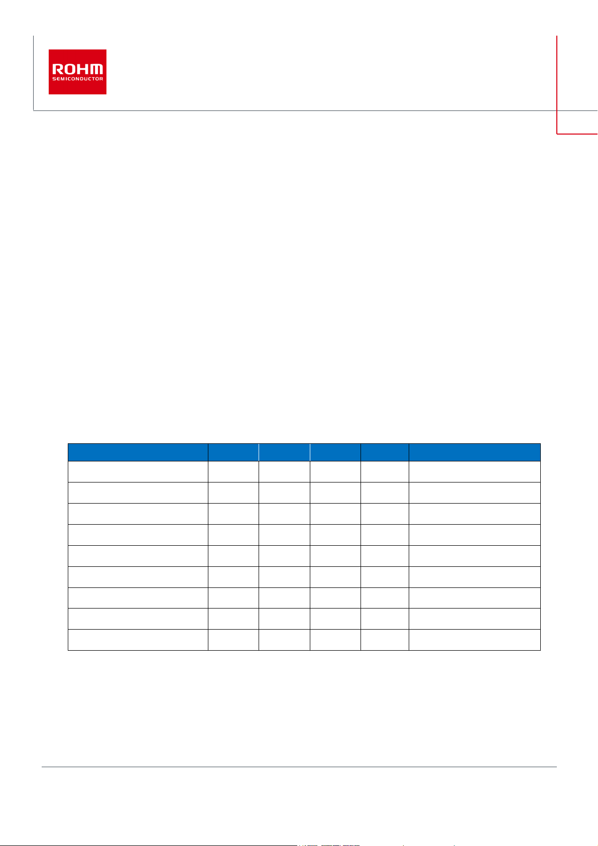
Electronics Characteristics
Not guarantee the characteristics, is representative value. Unless otherwise noted :VIN = 230Vac, I
= 1500mA, Ta:25°C
OUT
Parameter Min Typ Max Units Conditions
Input Voltage Range 90 230 264 Vac
Input Frequency 47 50/60 63 Hz
Output Voltage 13.5 15.0 16.5 V
Maximum Output Power - 15.0 22.5 W I
Output Current Range
(NOTE1)
Stand-by Power - 130 - mW I
Efficiency - 84.5 - %
Output Ripple Voltage
(NOTE2)
Operating Temperature Range -10 25 65 °C
(NOTE1) Please adjust operating time, within any parts surface temperature under 105°C
(NOTE2) Not include spike noise
0 1000 1500 mA
- 200 - mVpp
= 1500mA
OUT
= 0A
OUT
© 2018 ROHM Co., Ltd.
1/10
No. 61UG006E Rev.00
MAR.
Page 2
BM2P016T-EVK-002
1
2018
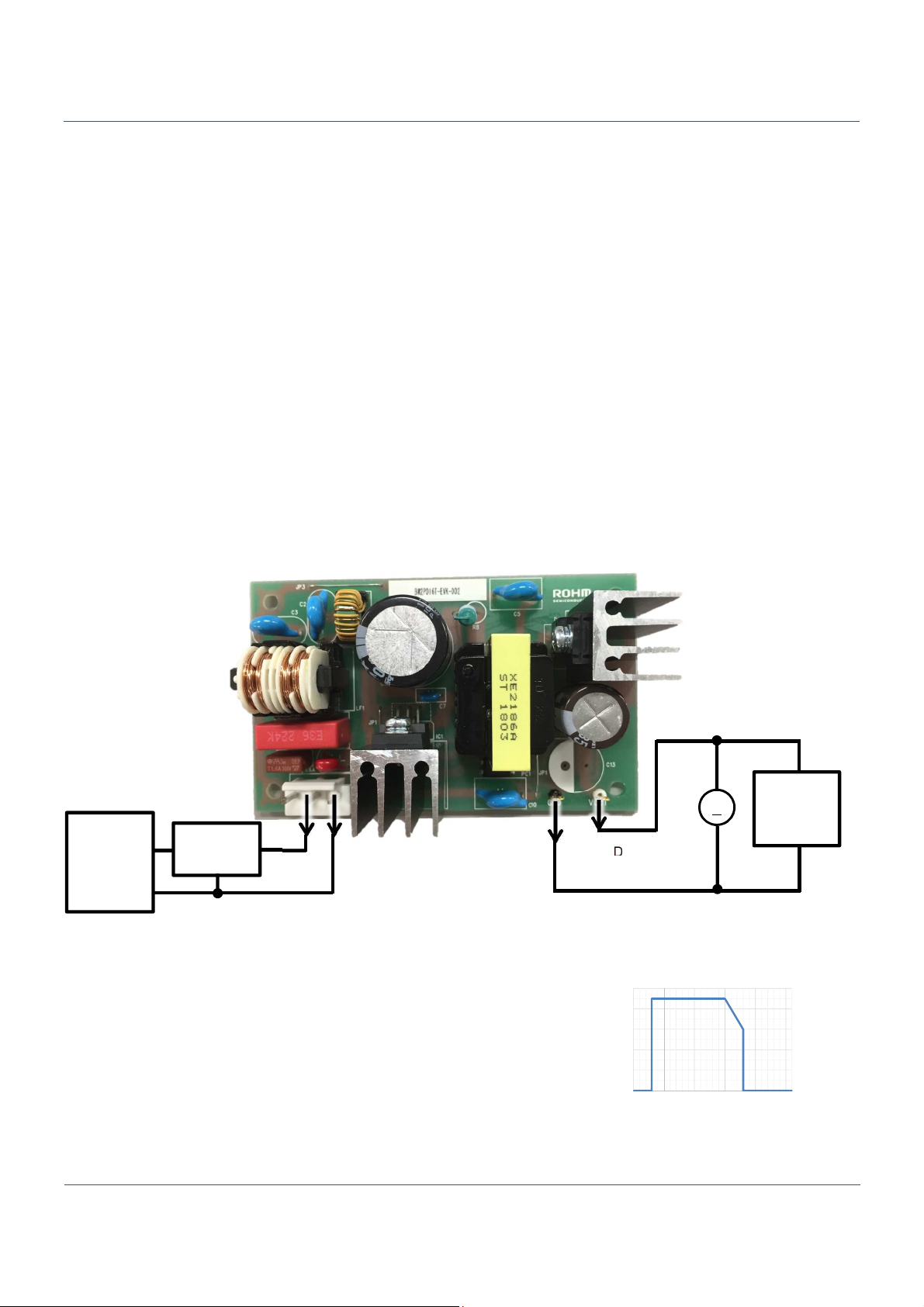
Operation Procedure
1. Operation Equipment
(1) AC Power supply 90Vac~264Vac, over 10W
(2) Electronic Load capacity 1.5A
(3) Multi meter
2. Connect method
(1) AC power supply presetting range 90~264Vac, Output switch is off.
(2) Load setting under 1.5A. Load switch is off.
(3) AC power supply N terminal connect to the board AC (N) of CN1, and L terminal connect to AC (L).
(4) Load + terminal connect to VOUT, GND terminal connect to GND terminal
(5) AC power meter connect between AC power supply and board.
(6) Output test equipment connects to output terminal
(7) AC power supply switch ON.
(8) Check that output voltage is 15V.
(9) Electronic load switch ON
(10) Check output voltage drop by load connect wire resistance
CN1 : from the left
①:AC (N), ②:AC (L)
AC Power
Supply
Power
Meter
DC Multi Meter
Figure 1. Connection Circuit
Deleting
Maximum Output Power Po of this reference board is 22.5W. The derating
curve is shown on the right.
Please adjust load continuous time by over 105°C of any parts surface
temperature within the operating temperature range (-10~65°C).
25.0
20.0
15.0
10.0
5.0
Output Power Po [W]
0.0
-25 0 25 50 75 100
Figure 2. Temperature Deleting curve
User’s Guide
+
V
−
Ambient Temparature Ta [℃]
Electronic
Load
© 2018 ROHM Co., Ltd.
2/10
No. 61UG006E Rev.00
MAR.
Page 3
BM2P016T-EVK-002
© 201
1
Reference
mm (inch)
C5
Core:EE25/20
User’s Guide
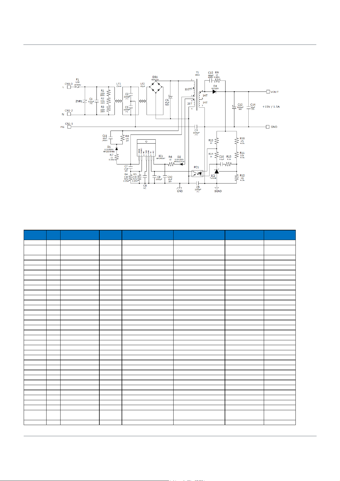
Schematics
VIN = 90~264Vac, V
OUT
= 15V
Figure 3. BM2P016T-EVK-002 Schematics
Bill of Materials
Table 1. BoM of BM2P016T-EVK-002
Part
C1 1 X2 Capacitor 0.1μF 300Vac, ±20% 890 334 025 027C S Wurth C2,C3,C4
C6 1 Electrolytic 47μF 450V, ±20% 450BXW47MEFR18x20 Rubycon 18mmΦX20mm
C7 1 Ceramic 47pF 1000V, X7R, ±10% RDE5C3A470J2K1H03B Murata C8 0 Ceramic NC - N.C. Taiyo Yuden 1608 (0603)
C9 1 Ceramic 1000pF 100V, X7R, ±10% HMK107B7102KA-T Taiyo Yuden 1608 (0603)
C10,C14 2 Ceramic 10μF 35V, X7R, ±20% GMK316AB7106ML-TR Taiyo Yuden 3216 (1206)
C11 1 Ceramic 10nF 630V, X7R, ±10% GRM31AR72J103KW01 Murata 3216 (1206)
C12 1 Electrolytic 1000uF 35V , ±20% UPA1V102MPD Nichicon
C15 1 Ceramic 680pF 1000V, X7R, ±10% GRM31BR73A681KW01 Murata 3216 (1206)
C16 1 Ceramic 3300pF 100V, X7R, ±10% HMK107B7332KA-T Taiyo Yuden DIP7
CN1 1 Connector 3pin 5mm pitch B3P-NV JST DB1 1 Bridge 1A 600V S1NB60-7062 Shindengen D1 1 FRD 0.2A 800V RFU02VSM8S ROHM TUMD2M
D2 1 FRD 0.5A 200V RF05VAM2S ROHM TUMD2M
D3 1 FRD 6A 200V RF601T2DNZ ROHM TO-220
F1 1 Fuse 1.6A 1.6A 300V 36911600000 Littelfuse HS1,HS2 2 Heat Sink - 22.9℃/W IC-1625-STL Sankyo Thermotec -
- 2 Skrew M3 M3 SEMS-SCREW-P4-3X8 TOMOHO IC1 1 AC/DC Converter - 650V BM2P016T-Z ROHM TO220-7
IC2 1 Shunt Regulator 120kΩ 2W, 700V, ±2% TL431BIDBZT TI SOT-23-3
LF1 1 Line Filter 13mH 1A XF1482Y Alpha Trans LF2 1 Line Filter 60μH 1A LF1246Y Alpha Trans PC1 1 Optocoupler - 5kV LTV-817-B LiteOn DIP4
R1,R2,R3 3 Resistor 220kΩ 0.25W, ±5% MCR18EZPJ224 ROHM 3216 (1206)
R4,R5 2 Resistor 0.82Ω 0.25W, ±1% MCR18EZHFLR820 ROHM 3216 (1206)
R6,R7,R9 3 Resistor 10Ω 0.25W, ±5% MCR18EZPJ100 ROHM 3216 (1206)
R8 1 Resistor 47kΩ 2W, 700V, ±2% ERG2SJ473 Panasonic R10 1 Resistor 47kΩ 0.1W, ±1% MCR03EZPFX4702 ROHM 1608 (0603)
R11 1 Resistor 3.3kΩ 0.1W, ±1% MCR03EZPFX3302 ROHM 1608 (0603)
R12 1 Resistor 10kΩ 0.1W, ±1% MCR03EZPFX1002 ROHM 1608 (0603)
R13,R14 2 Resistor 1kΩ 0.1W, ±5% MCR03EZPJ102 ROHM 1608 (0603)
R15 1 Resistor 5.1kΩ 0.1W, ±5% MCR03EZPJ512 ROHM 1608 (0603)
T1 1 Transformer -
ZNR1 1 Varistor - 300Vac, 423Vmin, 400A V470ZA05P Littelfuse 5mmΦ Disc
Qty. Type Value Description Part Number Ma nufacture
4 Y1 Capacitor 2200pF Y1 capacitor DE1E3KX222MB4BP01F Murata -
Bobin:EI-2506,
XE2186A Alpha Trans -
Configuration
12.5mmΦX20mm
8 ROHM Co., Ltd.
3/10
No. 61UG006E Rev.00
MAR.2018
Page 4
BM2P016T-EVK-002
© 201
1
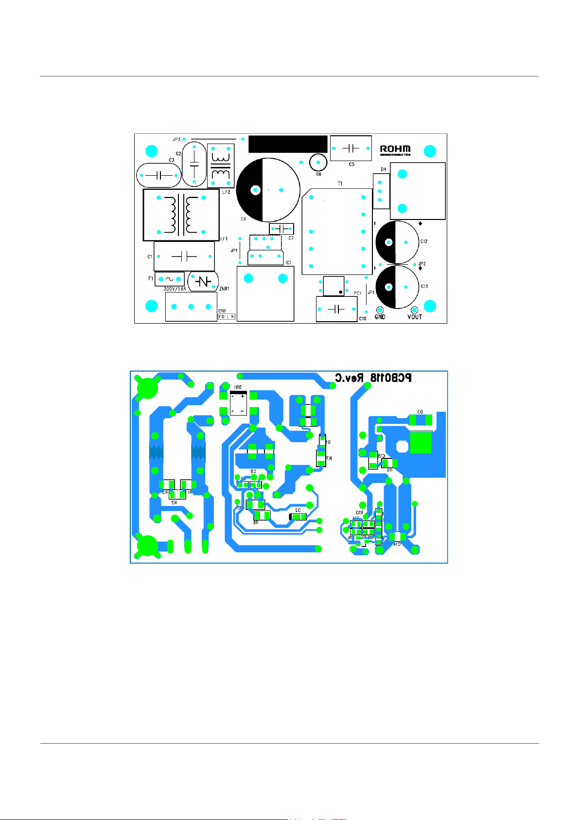
PCB
Size : 55 mm x 91 mm
User’s Guide
Figure 4. Top Silkscreen (Top view)
8 ROHM Co., Ltd.
Figure 5. Bottom Layout (Top view)
4/10
No. 61UG006E Rev.00
MAR.2018
Page 5

BM2P016T-EVK-002
© 201
1
Number of Turns
Winding*
Barrier
Insulation
Insulation Tape
1T
Insulation Tape
1T
Transformer Design
Product : XE2186A AlphaTrans Corp.
Bobbin : EI-2506 10PIN
Core : EE25/20 JSF
Figure 6. Connection Diagram Figure 7. Winding structure diagram
Table 2. Winding Specification
User’s Guide
NP1-2
NS1-2
NP2
NS1-1
NP1-1
Winding PIN
NP1-1
③→②
Winding
Material
Tape
2UEW 0.32 56T / 2Layer
Insulation Tape 1T
NS1-2
NP2
NS1-1
⑨→⑧
④→⑤
⑧→⑦
TEX-E 0.50 14T
2UEW 0.32 28T
TEX-E 0.50 14T
Insulation Tape 1T
NP1-2
②→①
2UEW 0.32 54T / 2Layer
Insulation Tape 3T
*All windings are closely wound
Inductance (Lp) 1000μH±10% (100kHz,1V)
Leakage Inductance 50μH MAX
Withstand Voltage Pri – Sec AC1500V
Sec - Core AC1500V
Pri – Core AC500V
Insulation resistance 100MΩ over (DC500V)
Manufacturer : Alfatrans Co., LTD.
〒541-0059 2-7-1 bakurou-cho, chu-o ku, osaka
http://www.alphatrans.jp/
Tape
8 ROHM Co., Ltd.
5/10
No. 61UG006E Rev.00
MAR.2018
Page 6

BM2P016T-EVK-002
© 201
1
Performance Data
・Constant Load Regulations
User’s Guide
16.5
16.0
15.5
15.0
VIN=100Vac
Output Voltage [V]
14.5
14.0
13.5
0 500 1000 1500 2000 2500
Output Current [mA]
Figure 8. Load Regulation (I
Table 3. Load Regulation (VIN=100Vac) Table 4. Load Regulation (VIN=230Vac)
I
V
OUT
375 mA
750 mA
1125 mA
1500 mA
Efficiency
OUT
14.981 V
14.976 V
14.971 V
14.966 V
OUT
vs. V
100
90
80
70
VIN=230Vac
60
50
Efficiency [%]
40
30
20
10
0
0 500 1000 1500
Output Current [mA]
) Figure 9. LOAD Regulation (I
OUT
I
V
OUT
84.35 %
85.74 %
85.11 %
84.43 %
375 mA
750 mA
1125 mA
1500 mA
vs. Efficiency)
OUT
Efficiency
OUT
14.980 V
14.975 V
14.971 V
14.965 V
VIN=100Vac
VIN=230Vac
80.14 %
82.58 %
84.93 %
84.52 %
8 ROHM Co., Ltd.
6/10
No. 61UG006E Rev.00
MAR.2018
Page 7

BM2P016T-EVK-002
© 201
1
・Power Consumption
User’s Guide
5.0
4.5
4.0
3.5
3.0
2.5
Power Loss [W]
2.0
1.5
1.0
0.5
0.0
0 500 1000 1500
Output Current [mA]
Figure 10. Load Regulation (I
・Constant AC Line Regulations
VIN=230Vac
VIN=100Vac
vs. P
OUT
0.7
0.6
0.5
0.4
0.3
Power Loss [W]
0.2
0.1
0.0
1 10 100
Output Current [mA]
) Figure 11. LOAD Regulation (I
LOSS
VIN=230Vac
VIN=100Vac
vs. P
OUT
LOSS
)
16.5
16.0
15.5
15.0
Output Voltage [V]
14.5
14.0
13.5
80 100 120 140 160 180 200 220 240 260 280
Input Voltage [Vac]
Figure 12. LINE Regulation (I
OUT
I
OUT
I
OUT
I
OUT
I
OUT
vs. V
100
90
80
70
= 20mA
=100mA
60
50
=1000mA
=1500mA
Efficiency [%]
40
30
20
10
0
80 100 120 140 160 180 200 220 240 260 280
Input Voltage [Vac]
) Figure 13. LINE Regulation (I
OUT
I
=1500mA
OUT
I
=1000mA
OUT
I
=100mA
OUT
I
= 20mA
OUT
vs. Efficiency)
OUT
8 ROHM Co., Ltd.
7/10
No. 61UG006E Rev.00
MAR.2018
Page 8

BM2P016T-EVK-002
© 201
1
・Switching Frequency
70
VIN=100Vac
60
50
40
30
20
Switching Frequency [kHz]
10
0
0 250 500 750 1000 1250 1500
Output Current [mA]
Figure 14. Switching Frequency (I
・Coil Peak Current
VIN=230Vac
vs. FSW)
OUT
User’s Guide
1.0
0.9
0.8
0.7
VIN=230Vac
0.6
VIN=100Vac
0.5
0.4
0.3
Primary Peak Current [A]
0.2
0.1
0.0
0 250 500 750 1000 1250 1500
Output Current [mA]
Figure 15. Primary Peak Current (I
OUT
vs. I
4.0
3.5
3.0
VIN=230Vac
2.5
2.0
1.5
Coil Peak Current [A]
1.0
0.5
0.0
0 250 500 750 1000 1250 1500
) Figure 16. Secondary Peak Current (I
peak
VIN=100Vac
Output Current [mA]
vs. I
OUT
peak
)
8 ROHM Co., Ltd.
8/10
No. 61UG006E Rev.00
MAR.2018
Page 9

BM2P016T-EVK-002
1
2018
・
VOUT Ripple Voltage
250
User’s Guide
200
150
100
Ripple Voltage [mVpp]
50
0
0 250 500 750 1000 1250 1500
Output Current [mA]
Figure 17. VOUT Ripple Voltage (I
Ripple Voltage: 39mVpp
VIN=230Vac
vs. V
OUT
VIN=100Vac
)
ripple
Ripple Voltage: 120mVpp
Ripple Voltage: 215mVpp
Figure 18. VOUT Ripple Voltage.1 Figure 19. VOUT Ripple Voltage.2 Figure 20. VOUT Ripple Voltage.3
VIN=100Vac, IOUT=10mA VIN=100Vac, I
=500mA VIN=100Vac, I
OUT
=1500mA
OUT
CH1: VOUT 50mV/div, 1000μs/div CH1: VOUT 50mV/div, 10μs/div CH1: VOUT 50mV/div, 10μs/div
Ripple Voltage: 209mVpp
Ripple Voltage: 69mVpp
Ripple Voltage: 135mVpp
Figure 21. VOUT Ripple Voltage.4 Figure 22. VOUT Ripple Voltage.5 Figure 23. VOUT Ripple Voltage.6
VIN=230Vac, IOUT=10mA VIN=230Vac, I
=500mA VIN=230Vac, I
OUT
=1500mA
OUT
CH1: VOUT 50mV/div, 1000μs/div CH1: VOUT 50mV/div, 10μs/div CH1: VOUT 50mV/div, 10μs/div
© 2018 ROHM Co., Ltd.
9/10
No. 61UG006E Rev.00
MAR.
Page 10

BM2P016T-EVK-002
© 201
1
VIN=90Vac,
I
=1
.5A
VIN=264Vac,
I
=1
.5A
・Operating Temperature
The Results were measured 30 minutes after startup.
Table 5. Parts surface temperature (Ta: 25°C)
Part
IC1 50.1 °C 56.0 °C
D1 64.9 °C 63.5 °C
DB1 65.0 °C 44.7 °C
T1 80.1 °C 81.2 °C
・EMI
OUT
User’s Guide
Condition
OUT
CISPR22.B
CISPR22.B
Figure 24. Conducted Emission.1 Figure 25. Conducted Emission.2
VIN=110Vac/60Hz, I
=1.5A VIN=230Vac/50Hz, I
OUT
OUT
=1.5A
QP margin= 11.7dB, AV margin=17.1dB QP margin= 11.1dB, AV margin=17.3dB
CISPR22.B
CISPR22.B
8 ROHM Co., Ltd.
Figure 26. Radiated Emission.1 Figure 27. Radiated Emission.2
VIN=110Vac/60Hz, I
=1.5A VIN=230Vac/50Hz, I
OUT
OUT
=1.5A
QP margin=13.9dB, AV margin=21.2dB QP margin= 9.6dB, AV margin=13.4dB
10/10
No. 61UG006E Rev.00
MAR.2018
Page 11

Notes
The information contained herein is subject to change without notice.
1)
Before you use our Products, please contact our sales representative
2)
tions :
Although ROHM is continuously working to improve product reliability and quality, semicon-
3)
ductors can break down and malfunction due to various factors.
Therefore, in order to prevent personal injury or fire arising from failure, please take safety
measures such as complying with the derating characteristics, implementing redundant and
fire prevention designs, and utilizing backups and fail-safe procedures. ROHM shall have no
responsibility for any damages arising out of the use of our Poducts beyond the rating specified by
ROHM.
Examples of application circuits, circuit constants and any other information contained herein are
4)
provided only to illustrate the standard usage and operations of the Products. The peripheral
conditions must be taken into account when designing circuits for mass production.
The technical information specified herein is intended only to show the typical functions of and
5)
examples of application circuits for the Products. ROHM does not grant you, explicitly or implicitly,
any license to use or exercise intellectual property or other rights held by ROHM or any other
parties. ROHM shall have no responsibility whatsoever for any dispute arising out of the use of
such technical information.
The Products specified in this document are not designed to be radiation tolerant.
6)
For use of our Products in applications requiring a high degree of reliability (as exemplified
7)
below), please contact and consult with a ROHM representative : transportation equipment (i.e.
cars, ships, trains), primary communication equipment, traffic lights, fire/crime prevention, safety
equipment, medical systems, servers, solar cells, and power transmission systems.
Do not use our Products in applications requiring extremely high reliability, such as aerospace
8)
equipment, nuclear power control systems, and submarine repeaters.
ROHM shall have no responsibility for any damages or injury arising from non-compliance with
9)
the recommended usage conditions and specifications contained herein.
ROHM has used reasonable care to ensurH the accuracy of the information contained in this
10)
document. However, ROHM does not warrants that such information is error-free, and ROHM
shall have no responsibility for any damages arising from any inaccuracy or misprint of such
information.
Please use the Products in accordance with any applicable environmental laws and regulations,
11)
such as the RoHS Directive. For more details, including RoHS compatibility, please contact a
ROHM sales office. ROHM shall have no responsibility for any damages or losses resulting
non-compliance with any applicable laws or regulations.
When providing our Products and technologies contained in this document to other countries,
12)
you must abide by the procedures and provisions stipulated in all applicable export laws and
regulations, including without limitation the US Export Administration Regulations and the Foreign
Exchange and Foreign Trade Act.
This document, in part or in whole, may not be reprinted or reproduced without prior consent of
13)
ROHM.
and verify the latest specifica-
Notice
ZZZURKPFRP
652+0&R/WG$OOULJKWVUHVHUYHG
Thank you for your accessing to ROHM product informations.
More detail product informations and catalogs are available, please contact us.
ROHM Customer Support System
http://www.rohm.com/contact/
5
%
Page 12

■<High Voltage Safety Precautions>
◇ Read all safety precautions before use
Please note that this document covers only the BM2P016T-Z evaluation board
(BM2P016T-EVK-002) and its functions. For additional information, please refer to the
datasheet.
To ensure safe operation, please carefully read all precautions
before handling the evaluation board
Depending on the configuration of the board and voltages used,
Potentially lethal voltages may be generated.
Therefore, please make sure to read and observe all safety precautions
described in the red box below.
Before Use
[1] Verify that the parts/components are not damaged or missing (i.e. due to the drops).
[2] Check that there are no conductive foreign objects on the board.
[3] Be careful when performing soldering on the module and/or evaluation board to ensure that
solder splash does not occur.
[4] Check that there is no condensation or water droplets on the circuit board.
During Use
[5] Be careful to not allow conductive objects to come into contact with the board.
[6] Brief accidental contact or even bringing your hand close to the board may result in
discharge and lead to severe injury or death.
Therefore, DO NOT touch the board with your bare hands or bring them too close to
the board.
In addition, as mentioned above please exercise extreme caution when using conductive
tools such as tweezers and screwdrivers.
[7] If used under conditions beyond its rated voltage, it may cause defects such as short-circuit
or, depending on the circumstances, explosion or other permanent damages.
[8] Be sure to wear insulated gloves when handling is required during operation.
After Use
[9] The ROHM Evaluation Board contains the circuits which store the high voltage. Since it
stores the charges even after the connected power circuits are cut, please discharge the
electricity after using it, and please deal with it after confirming such electric discharge.
[10] Protect against electric shocks by wearing insulated gloves when handling.
This evaluation board is intended for use only in research and development facilities and should by
handled
procedures.
We recommend carrying out operation in a safe environment that includes the use of high voltage
signage at all entrances, safety interlocks, and protective glasses.
only by qualified personnel familiar with all safety and operating
 Loading...