


System Lens Driver for Digital Still Cameras / Single-lens Reflex Cameras
5ch System Lens Drivers
for Digital Still Cameras
BD6370GUL, BD6758MWV, BD6758KN
No.09014EAT01
●Description
The BD6370GUL motor driver provides 3 Constant-Voltage Drive / Full-ON Drive H-bridge channels, 1 Constant-Voltage
Drive / Linear Constant-Current Drive / Full-ON Drive H-bridge channel, and 1 Constant-Current Drive H-bridge channel,
while the BD6758MWV and the BD6758KN provides 4 Full-ON Drive H-bridge channels and 1 Linear Constant-Current
Drive H-bridge channel.
A Stepping motor can be used for auto focus and a DC motor for zoom and iris. ROHM offers both an advance type equipped
with a D/A converter in all channels and a standard type, allowing selection of the ideal unit depending on the application.
●Features
1) Subminiature 24PIN Wafer-level CSP (Chip Size Package): 2.6 x 2.6 x 0.55mm
3
(BD6370GUL)
2) Resemblance 6ch drive function (BD6370GUL)
3) Drive type selection (BD6370GUL)
4) Low ON-Resistance Power CMOS output:
All blocks (Const.-V/Full-ON Drive, Const.-V/Const.-C/Full-ON Drive, and Const.-Current Drive) with 1.4Ω Typ. (BD6370GUL)
Full-ON Drive block with 1.2Ω Typ. and Linear Constant-Current Drive block with 1.0Ω Typ. (BD6758MWV / KN)
5) Serial interface 3-line bus control input (BD6370GUL)
6) Built-in Constant-Voltage control 6-bit D/A converter and Constant-Current control 6-bit D/A converter resolution (BD6370GUL)
7) Built-in ±5% high-precision Constant-Voltage Driver (BD6370GUL)
8) Built-in ±3% high-precision Linear Constant-Current Driver
9) Constant-Voltage Drive block and Constant-Current Drive block features phase compensation capacitor-free design
10) 1.2V±3% high-precision reference voltage output (BD6758MWV / KN)
11) Drive mode switching function (BD6758MWV / KN)
12) UVLO (Under Voltage Lockout Protection) function
13) Built-in TSD (Thermal Shut Down) circuit
14) Standby current consumption: 0μA Typ.
●Absolute Maximum Ratings
Parameter Symbol
BD6370GUL BD6758MWV BD6758KN
Limit
Unit
Power supply voltage VCC -0.3 to +6.5 0 to +7.0 0 to +7.0 V
Motor power supply voltage VM -0.3 to +6.5 0 to +7.0 0 to +7.0 V
Control input voltage VIN -0.3 to VCC+0.3 0 to VCC 0 to VCC V
Power dissipation Pd 830
1
※
880
2
※
875
3
※
mW
Operating temperature range Topr -25 to +85 -25 to +85 -25 to +85 °C
Junction temperature Tjmax +150 +150 +150 °C
Storage temperature range Tstg -55 to +150 -55 to +150 -55 to +150 °C
H-bridge output current Iout -500 to +500
※1 Reduced by 6.64mW/°C over 25°C, when mounted on a glass epoxy board (50mm 58mm 1.75mm; 8layers).
※2 Reduced by 7.0mW/°C over 25°C, when mounted on a glass epoxy board (74.2mm 74.2mm 1.6mm).
※3 Reduced by 7.0mW/°C over 25°C, when mounted on a glass epoxy board (70mm 70mm 1.6mm).
※4 Must not exceed Pd, ASO, or Tjmax of 150°C.
4
※
-800 to +800
4
※
-800 to +800
4
※
mA/ch
www.rohm.co
© 2009 ROHM Co., Ltd. All rights reserved.
1/32
2009.06 - Rev.A

BD6370GUL, BD6758MWV, BD6758KN
Technical Note
●Operating Conditions (Ta=-25 to +85°C)
Parameter Symbol
BD6370GUL BD6758MWV BD6758KN
Limit Unit
Power supply voltage VCC 2.7 to 5.5 2.5 to 5.5 2.5 to 5.5 V
Motor power supply voltage VM 2.7 to 5.5 2.5 to 5.5 2.5 to 5.5 V
Control input voltage VIN 0 to VCC 0 to VCC 0 to VCC V
Control input frequency FIN 100
Serial clock input frequency FSCLK 10
H-bridge output current Iout -400 to +400
※5 ON duty=50%
※6 Must not exceed Pd or ASO.
5
※
100
5
※
- - MHz
6
※
-500 to +500
5
※
100
6
※
-500 to +500
5
※
kHz
6
※
mA/ch
●Electrical Characteristics and Diagrams
1) BD6370GUL Electrical DC Characteristics (Unless otherwise specified, Ta=25°C, VCC=3.0V, VM=5.0V)
Parameter Symbol
Min. Typ. Max.
Limit
Unit Conditions
Overall
Circuit current (Standby mode) ICCST - 0 3.0 μA PS=0V
Circuit current (Active mode) ICC - 1.3 2.0 mA PS=3V with no control signal, and no load
Control input (IN=PS, INPUT1, 2, 34, 45, STROBE, SCLK, and SDATA)
High level input voltage VINH 2.0 - VCC V
Low level input voltage VINL 0 - 0.7 V
High level input current 1 IINH1 15 30 60 μA VINH1 (PS, INPUT1, 2, 34, 45) =3V
High level input current 2 IINH2 7.5 15 30 μA VINH2 (STROBE, SCLK, SDATA) =3V
Low level input current IINL -1 0 - μA VINL=0V
UVLO
UVLO voltage VUVLO 1.6 - 2.4 V
Constant-Voltage Drive / Full-ON Drive block (ch1 to ch3)
Output ON-Resistance RON - 1.40 1.75 Ω Io=±400mA on high and low sides in total
Output high voltage 1 VVOH1 1.35 1.50 1.65 V DACx=6’b01_0100, RL=20Ω
Output high voltage 2 VVOH2 2.85 3.00 3.15 V DACx=6’b10_1000, RL=20Ω
Output high voltage 3 VVOH3 4.49 4.725 4.96 V DACx=6’b11_1111, RL=20Ω
DAC resolution DVRES - 6 - BITS 75mV/LSB
Differential non-linear tolerance DVDNL -1 - 1 LSB
Integral non-linear tolerance DVINL -2 - 2 LSB
Min. voltage of DAC setting DVRNG 1.5 - - V DACx=6’b01_0100
Constant-Voltage Drive / Constant-Current Drive / Full-ON Drive block (ch4)
Output ON-Resistance RON - 1.40 1.75 Ω Io=±400mA on high and low sides in total
Constant-Voltage Drive block in ch4
Output high voltage 1 VVOH1 1.35 1.50 1.65 V DACV4=6’b01_0100, RL=20Ω
Output high voltage 2 VVOH2 2.85 3.00 3.15 V DACV4=6’b10_1000, RL=20Ω
Output high voltage 3 VVOH3 4.49 4.725 4.96 V DACV4=6’b11_1111, RL=20Ω
DAC resolution DVRES - 6 - BITS 75mV/LSB
Differential non-linear tolerance DVDNL -1 - 1 LSB
Integral non-linear tolerance DVINL -2 - 2 LSB
Min. voltage of DAC setting DVRNG 1.5 - - V DACV4=6’b01_0100
Constant-Current Drive block in ch4
RNF voltage 1 VIRNF1 40 50 60 mV DACI4=6’b00_1010, R
RNF voltage 2 VIRNF2 94 99 104 mV DACI4=6’b01_0100, R
RNF voltage 3 VIRNF3 178 198 218 mV DACI4=6’b10_1000, R
=0.5Ω, RL=10Ω
RNF4
=0.5Ω, RL=10Ω
RNF4
=0.5Ω, RL=10Ω
RNF4
DAC resolution DIRES - 6 - BITS 5mV/LSB
Differential non-linear tolerance DIDNL -1 - 1 LSB
Integral non-linear tolerance DIINL -2 - 2 LSB
Min. voltage of DAC setting DIRNG 50 - - mV DACI4=6’b00_1010
Constant-Current Drive block (ch5)
Output ON-Resistance RON - 1.4 1.75 Ω Io=±400mA on high and low sides in total
RNF voltage 1 VIRNF1 38 48 58 mV DAC5=6’b00_1010, R
RNF voltage 2 VIRNF2 91 96 101 mV DAC5=6’b01_0100, R
RNF voltage 3 VIRNF3 172 192 212 mV DAC5=6’b10_1000, R
=0.5Ω, RL=10Ω
RNF5
=0.5Ω, RL=10Ω
RNF5
=0.5Ω, RL=10Ω
RNF5
DAC resolution DIRES - 6 - BITS 5mV/LSB
Differential non-linear tolerance DIDNL -1 - 1 LSB
Integral non-linear tolerance DIINL -2 - 2 LSB
Min. voltage of DAC setting DIRNG 50 - - mV DAC5=6’b00_1010
www.rohm.co
© 2009 ROHM Co., Ltd. All rights reserved.
2/32
2009.06 - Rev.A

]
BD6370GUL, BD6758MWV, BD6758KN
Technical Note
2) BD6370GUL Electrical DC Characteristic Diagrams
5.0
4.0
3.0
2.0
Circuit current : ICC [mA
1.0
0.0
0.0 1.0 2.0 3.0 4.0 5.0 6.0 7. 0
Supply voltag e : VCC [V]
Fig.1 Circuit Current
(Active mode)
BD6370GUL
Top 8 5 ° C
Mid 25°C
Low -25°C
Op. range
(2.7V to 5.5V)
5.0
4.0
3.0
2.0
1.0
Output ON resistance : RON [Ω]
0.0
0.0 1.0 2.0 3.0 4.0 5.0 6.0 7.0
Supply voltage : VM [V]
Fig.2 Output ON-Resistance
(ch1 to ch3)
BD6370GUL
Top 8 5 ° C
Mid 25°C
Low -25°C
Op. range
(2.7V to 5.5V)
5.0
4.0
3.0
2.0
1.0
Output ON resistance : RON [Ω]
0.0
0.01.02.03.04.05.06.07.0
Supply voltage : VM [V]
Fig.3 Output ON-Resistance
(ch4 to ch5)
BD6370GUL
Top 8 5 ° C
Mid 25°C
Low -25°C
Op. range
(2.7V to 5.5V)
1.0
0.5
0.0
-0.5
Diff. non-linear tolerance : DVDNL [LSB]
-1.0
0 8 16 24 32 40 48 56 64
Serial setting value : D AC code [BI T]
Fig.4 Differential Non-Linear
-25°C
Tolerance
BD6370GUL
85°C
25°C
Operating range
2.0
1.0
0.0
-1.0
Integ.non-linear tolerance: DVINL [LSB]
-2.0
0 8 16 24 32 40 48 56 64
Serial setting value : D AC code [BIT]
BD6370GUL
25°C
-25°C
85°C
Operating range
Fig.5 Integral Non-Linear Tolerance
(Const.-Voltage drive block, RL=20Ω)
20
10
0
-10
Output high voltage accuracy: VVOH [%]
-20
0 8 16 24 32 40 48 56 64
Serial setting value : D AC code [BIT]
Fig.6 Output High Voltage Accuracy
(Const.-Voltage drive block, RL=20Ω)
BD6370GUL
25°C
85°C
Operating range
-25°C
1.0
0.5
0.0
-0.5
Diff. non-linear tolerance : DIDNL [LSB]
-1.0
Fig.7 Differential Non-Linear
25°C
85°C
Operating range
0 8 16 24 32 40 48 56 64
Serial setting value : D AC code [BIT]
Tolerance
-25°C
BD6370GUL
2.0
Integ.non-linear tolerance: DIINL [LSB]
1.0
0.0
-1.0
-2.0
-25°C
Operating range
0 8 16 24 32 40 48 56 64
Serial setting value : D AC code [BIT]
BD6370GUL
25°C
85°C
Fig.8 Integral Non-Linear Tolerance
(Const.-Current drive block, R
=0.5Ω, RL=10Ω)
RNFx
20
10
0
-10
RNF voltage accuracy: VIRNF [%]
-20
0 8 16 24 32 40 48 56 64
Serial setting value : D AC code [BIT]
-25°C
Operating range
BD6370GUL
85°C
Fig.9 RNF Voltage Accuracy
(Const.-Current drive block, R
=0.5Ω, RL=10Ω)
RNFx
25°C
1.0
0.5
0.0
-0.5
Diff. non-linear tolerance : DIDNL [LSB]
-1.0
0 8 16 24 32 40 48 56 64
Serial setting value : D AC code [BIT]
Fig.10 Differential Non-Linear
Tolerance
BD6370GUL
85°C 25°C-25°C
Operating range
2.0
1.0
0.0
-1.0
Integ.non-linear tolerance: DIINL [LSB]
-2.0
0 8 16 24 32 40 48 56 64
Serial setting value : DA C c ode [BIT]
BD6370GUL
25°C
85°C
Operating range
Fig.11 Integral Non-Linear
Tolerance
-25°C
20
10
0
-10
RNF voltage accuracy: VIRNF [%]
-20
0 8 16 24 32 40 48 56 64
Serial setting value : D AC code [BIT]
BD6370GUL
25°C
Operating Range
Fig.12 RNF Voltage Accuracy
(Const.-Current drive block, R
=1.0Ω, RL=10Ω)
RNFx
-25°C
85°C
www.rohm.co
© 2009 ROHM Co., Ltd. All rights reserved.
3/32
2009.06 - Rev.A
BD6370GUL, BD6758MWV, BD6758KN
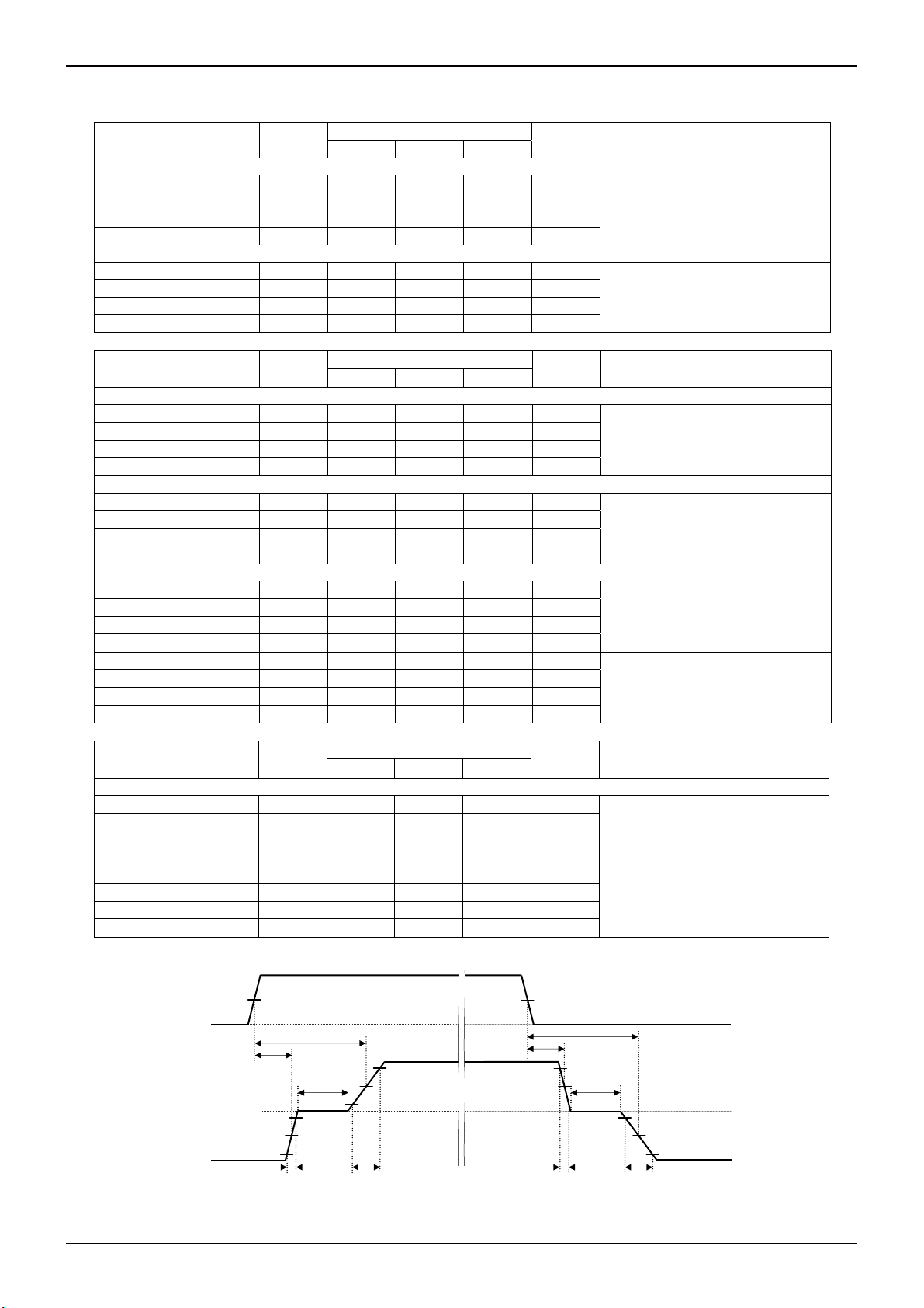
3) BD6370GUL Electrical AC Characteristics (Unless otherwise specified, Ta=25°C, VCC=3.0V, VM=5.0V)
Constant-Voltage / Full-ON Type Drive blocks (ch1 to ch3)
Parameter Symbol
Information
ch1 ch2 ch3
7
※
Unit Conditions
Full-ON Drive Mode
Turn on time ton 1.11 1.04 1.10 μs
Turn off time toff 0.06 0.06 0.06 μs
Rise time tr 1.64 1.42 1.50 μs
DACx=6’b11_1111, RL=20Ω
Fall time tf 0.01 0.01 0.01 μs
Constant-Voltage Drive Mode
Turn on time ton 1.26 1.23 1.22 μs
Turn off time toff 0.04 0.04 0.04 μs
Rise time tr 1.31 1.35 1.30 μs
DACx=6’b10_1000, RL=20Ω
Fall time tf 0.02 0.02 0.02 μs
Constant-Voltage / Constant-Current / Full-ON Type Drive block (ch4)
Parameter Symbol
Information
- ch4 -
7
※
Unit Conditions
Full-ON Drive Mode
Turn on time ton - 0.76 - μs
Turn off time toff - 0.05 - μs
Rise time tr - 0.68 - μs
Fall time tf - 0.02 - μs
DACV4=6’b11_1111,
DACI4=6’b11_1111,
RL=20Ω
Constant-Voltage Drive Mode
Turn on time ton - 1.19 - μs
Turn off time toff - 0.04 - μs
Rise time tr - 1.31 - μs
Fall time tf - 0.01 - μs
DACV4=6’b10_1000,
DACI4=6’b11_1111,
RL=20Ω
Constant-Current Drive Mode
Turn on time ton - 0.83 - μs
Turn off time toff - 0.05 - μs
Rise time tr - 0.89 - μs
Fall time tf - 0.03 - μs
Turn on time ton - 0.69 - μs
Turn off time toff - 0.04 - μs
Rise time tr - 0.29 - μs
Fall time tf - 0.03 - μs
Constant-Current Type Drive block (ch5)
Parameter Symbol
Information
- ch5 -
7
※
Unit Conditions
DACV4=6’b11_1111,
DACI4=6’b10_1100 (I
R
=0.5Ω, RL=10Ω,
RNFI4
R
=4mΩ, RW=40mΩ
METALI4
DACV4=6’b11_1111,
DACI4=6’b10_1010 (IO=200mA),
=1.0Ω, RL=10Ω,
R
RNFI4
R
=4mΩ, RW=40mΩ
METALI4
Constant-Current Drive Mode
Turn on time ton - 0.77 - μs
Turn off time toff - 0.04 - μs
Rise time tr - 0.47 - μs
Fall time tf - 0.04 - μs
Turn on time ton - 0.69 - μs
Turn off time toff - 0.04 - μs
Rise time tr - 0.24 - μs
Fall time tf - 0.02 - μs
※7 AC characteristics are reference values, then the performance of IC’s characteristics is not guaranteed.
DAC5=6’b10_1101 (I
=0.5Ω, RL=10Ω,
R
RNF5
R
=22mΩ, RW=40mΩ
METAL5
DAC5=6’b10_1010 (I
=1.0Ω, RL=10Ω,
R
RNF5
R
=22mΩ, RW=40mΩ
METAL5
INPUTx
50%
50%
OUTxA-OUTxB current
ton
toff
Dead
Time
-10%
-50%
-90%
tf tr
10%
90%
50%
ton
toff
90%
50%
Dead
Time
10%
tf tr
-10%
-50%
-90%
Fig.13 The Definition of I/O Switching
Waveforms
Technical Note
=400mA),
O
=400mA),
O
=200mA),
O
100%
0%
100%
0%
-100%
www.rohm.co
© 2009 ROHM Co., Ltd. All rights reserved.
4/32
2009.06 - Rev.A

BD6370GUL, BD6758MWV, BD6758KN
4) BD6370GUL Electrical AC Characteristic Diagrams
BD6370GUL
BD6370GUL
INPUT1,2,or34
voltage
[5V/div]
INPUT1,2,or34
voltage
[5V/div]
INPUT34or45
voltage
[5V/div]
OUTxA-xB
[100mA/div]
current
OUTxA-xB
current
[100mA/div]
OUT4A-4B
current
[100mA/div]
[500nsec/div]
[500nsec/div]
Fig.14 I/O AC Responses (ton, tr)
ch1 to ch3 Full-ON Drive Mode
DACx=6’b11_1111, RL=20Ω
BD6370GUL
Fig.15 I/O AC Responses (ton, tr)
ch1 to ch3Constant-Voltage Drive Mode
DACx=6’b10_1000, RL=20Ω
BD6370GUL
Fig.16 I/O AC Responses (ton, tr)
ch4 Full-ON Drive Mode
DACV4=DACI4=6’b11_1111, RL=20Ω
INPUT1,2,or34
voltage
[5V/div]
INPUT1,2,or34
voltage
[5V/div]
INPUT34or45
voltage
[5V/div]
OUTxA-xB
[100mA/div]
current
OUTxA-xB
current
[100mA/div]
OUT4A-4B
current
[100mA/div]
[20nsec/div]
[20nsec/div]
Fig.17 I/O AC Responses (toff, tf)
ch1 to ch3 Full-ON Drive Mode
DACx=6’b11_1111, RL=20Ω
Fig.18 I/O AC Responses (toff, tf)
ch1 to ch3Constant-Voltage Drive Mode
DACx=6’b10_1000, RL=20Ω
Fig.19 I/O AC Responses (toff, tf)
ch4 Full-ON Drive Mode
DACV4=DACI4=6’b11_1111, RL=20Ω
BD6370GUL
BD6370GUL
INPUT34or45
voltage
[5V/div]
INPUT34or45
voltage
[5V/div]
OUT4A-4B
[100mA/div]
current
OUT4A-4B
current
[200mA/div]
OUT5A-5B
current
[200mA/div]
[500nsec/div]
[500nsec/div]
Fig.20 I/O AC Responses (ton, tr)
ch4 Constant-Voltage Drive Mode
DACV4=6’b10_1000, DACI4=6’b11_1111, RL=20Ω
Fig.21 I/O AC Responses (ton, tr)
ch4 Constant-Current Drive Mode
DACV4=6’b11_1111, DACI4=6’b10_1100, R
=0.5Ω, RL=10Ω
RNFI4
Fig.22 I/O AC Responses (ton, tr)
ch5 Constant-Current Drive Mode
DAC5=6’b10_1101, R
BD6370GUL
BD6370GUL
INPUT34or45
voltage
[5V/div]
INPUT34or45
voltage
[5V/div]
INPUT45
voltage
[5V/div]
OUT4A-4B
[100mA/div]
current
OUT4A-4B
current
[200mA/div]
OUT5A-5B
current
[200mA/div]
Fig.23 I/O AC Responses (toff, tf)
ch4 Constant-Voltage Drive Mode
DACV4=6’b10_1000, DACI4=6’b11_1111, RL=20Ω
[20nsec/div]
Fig.24 I/O AC Responses (toff, tf)
DACV4=6’b11_1111, DACI4=6’b10_1100, R
ch4 Constant-Current Drive Mode
[20nsec/div]
=0.5Ω, RL=10Ω
RNFI4
Fig.25 I/O AC Responses (toff, tf)
ch5 Constant-Current Drive Mode
DAC5=6’b10_1101, R
AC characteristics are reference values, then the performance of IC’s characteristics is not guaranteed.
Technical Note
BD6370GUL
[500nsec/div]
BD6370GUL
[20nsec/div]
BD6370GUL
[500nsec/div]
=0.5Ω, RL=10Ω
RNF5
BD6370GUL
[20nsec/div]
=0.5Ω, RL=10Ω
RNF5
www.rohm.co
© 2009 ROHM Co., Ltd. All rights reserved.
5/32
2009.06 - Rev.A

BD6370GUL, BD6758MWV, BD6758KN
Technical Note
BD6370GUL
BD6370GUL
INPUT34or45
voltage
[5V/div]
OUT4A-4B
[200mA/div]
current
OUT5A-5B
current
[200mA/div]
[500nsec/div]
[500nsec/div]
Fig.26 I/O AC Responses (ton, tr)
DACV4=6’b11_1111, DACI4=6’b10_1010, R
ch4 Constant-Current Drive Mode
=1.0Ω, RL=10Ω
RNFI4
Fig.27 I/O AC Responses (ton, tr)
ch5 Constant-Current Drive Mode
DAC5=6’b10_1010, R
=1.0Ω, RL=10Ω
RNF5
BD6370GUL
BD6370GUL
INPUT34or45
voltage
[5V/div]
INPUT45
voltage
[5V/div]
OUT4A-4B
[200mA/div]
current
OUT5A-5B
current
[200mA/div]
[20nsec/div]
[20nsec/div]
Fig.28 I/O AC Responses (toff, tf)
DACV4=6’b11_1111, DACI4=6’b10_1010, R
ch4 Constant-Current Drive Mode
=1.0Ω, RL=10Ω
RNFI4
Fig.29 I/O AC Responses (toff, tf)
ch5 Constant-Current Drive Mode
DAC5=6’b10_1010, R
=1.0Ω, RL=10Ω
RNF5
AC characteristics are reference values, then the performance of IC’s characteristics is not guaranteed.
5) BD6758MWV and BD6758KN Electrical Characteristics (Unless otherwise specified, Ta=25°C, VCC=3.0V, VM=5.0V)
Parameter
Symbol
Min. Typ. Max.
Limit
Unit
Conditions
Overall
Circuit current
during standby operation
ICCST - 0 10 μA PS=0V
Circuit current ICC - 1.4 2.5 mA PS=VCC with no signal
Control input (IN=PS, IN1A to 5B, SEL1 to 2, BRK1 to 2, EN1, and IN5)
High level input voltage VINH 2.0 - - V
Low level input voltage VINL - - 0.7 V
High level input current IINH 15 30 60 μA VINH=3V
Low level input current IINL -1 0 - μA IVINL=0V
Pull-down resistor RIN 50 100 200 kΩ
UVLO
UVLO voltage VUVLO 1.6 - 2.4 V
Full-ON Drive block (ch1 to ch4)
Output ON-Resistance RON - 1.2 1.5 Ω Io=±400mA on high and low sides in total
Linear Constant-Current Drive block (ch5)
Output ON-Resistance RON - 1.0 1.25 Ω Io=±400mA on high and low sides in total
VREF output voltage VREF 1.16 1.20 1.24 V Iout=0~1mA
Output limit voltage VOL 194 200 206 mV RNF=0.5Ω, VLIM=0.2V
www.rohm.co
© 2009 ROHM Co., Ltd. All rights reserved.
6/32
2009.06 - Rev.A

]
BD6370GUL, BD6758MWV, BD6758KN
Technical Note
6) BD6758MWV and BD6758KN Electrical AC Characteristic Diagrams
5.0
4.0
3.0
2.0
Circuit current : ICC [mA
1.0
0.0
0.0 1.0 2. 0 3.0 4.0 5.0 6.0 7.0
Fig.30 Circuit current
BD6758MWV, BD6758KN
Top 8 5 ° C
Mid 25°C
Low -25°C
Op. range
(2.5V to 5.5V)
Supply voltag e : VCC [V]
5.0
4.0
3.0
2.0
1.0
Output ON resistance : RON [Ω]
0.0
0.0 1.0 2.0 3.0 4.0 5.0 6.0 7.0
Fig.31 Output ON-Resistance
BD6758MWV, BD6758KN
Top 8 5 ° C
Mid 25°C
Low -25°C
Op. range
(2.5V to 5.5V)
Supply voltage : VM [V]
(Full-ON Drive block)
5.0
4.0
3.0
2.0
1.0
Output ON resistance : RON [Ω]
0.0
0.0 1.0 2.0 3.0 4.0 5.0 6.0 7.0
Fig.32 Output ON-Resistance
(Linear Constant-Current Drive block)
BD6758MWV, BD6758KN
Top 8 5 ° C
Mid 25°C
Low -25°C
Op. range
(2.5V to 5.5V)
Supply voltage : VM [V]
250
200
BD6758MWV, BD6758KN
150
100
50
RNF voltage : VRNF [mV]
0
0 50 100 150 200 250
VLIM voltage : VLIM [mV]
Fig.33 Output limit voltage
(RNF=0.5Ω)
Top 8 5 ° C
Mid 25°C
Low -25°C
●Power Dissipation Reduction
1000
800
600
400
830mW
432mW
BD6370GUL
1000
880mW
800
600
458mW
400
200
Power dissipation : Pd [mW]
0
0 25 50 75 100 125 150
Ambient temperature : Ta [°C]
Fig.34 Power Dissipation
Reduction
85°C
200
Power dissipation : Pd [mW]
0
0 25 50 75 100 125 150
Ambient temperature : Ta [°C]
Fig.35 Power Dissipation
Reduction
BD6758MWV
85°C
1000
875mW
800
600
455mW
400
200
Power dissipation : Pd [mW]
0
0 25 50 75 100 125 150
Ambient temperature : Ta [°C]
85°C
Fig.36 Power Dissipation
Reduction
BD6758KN
www.rohm.co
© 2009 ROHM Co., Ltd. All rights reserved.
7/32
2009.06 - Rev.A

A4A
A
A1A
BD6370GUL, BD6758MWV, BD6758KN
●Block Diagram, Pin Arrangement, and Pin Function
PS
B3
Power Save & Serial Reset
VCC
E3
TSD & UVLO
INPUT1
INPUT2
Serial Interface
D3
C3
Serial Interface
Logic12
Serial Interface
Level Shift
&
Pre Driver
6bit DAC
12
V
DAC12
STROBE
SCLK
SDATA
INPUT34
INPUT45
Serial Interface
B4
D4
C4
Serial Interface
D2
C2
Serial
Interface
Selector
Logic3
Serial Interface
Selector
Logic4
Serial Interface
Serial Interface
Level Shift
&
Pre Driver
6bit DAC
Level Shift
&
Pre Driver
6bit DAC
6bit DAC
V4
V
DAC3
3
V
DACI4
I4
V
DACV4
BandGap
H bridge
C.V./Full ON
H bridge
C.V./Full ON
H bridge
C.V./Full ON
H bridge
C.V./C.C./Full ON
Serial Interface
B5
C5
D5
E4
E5
B1
Technical Note
OUT1A
OUT1B
5
OUT2A
OUT2B
OUT3A
OUT3B
PGND
1 2 3 4 5
3
VM
A RNF4 OUT4A VM OUT1A OUT1B
2
OUT4A
OUT4B
B OUT4B
RNF4
C OUT5A INPUT45 INPUT2 SDATA OUT2B
D OUT5B INPUT34 INPUT1 SCLK OUT3A
INDEX
POST
PS STROBE OUT2A
Serial Interface
Logic5
Serial Interface
Level Shift
&
Pre Driver
6bit DAC
E2
GND
C1
D1
E1
OUT5A
E RNF5 GND VCC OUT3B PGND
OUT5B
RNF5
H bridge
Const. Current
V
DAC5
5
Fig.37 BD6370GUL Block Diagram Fig.38 BD6370GUL Pin Arrangement (Top View)
VCSP50L2 Package
BD6370GUL Pin Function Table
No.
Pin
Name
Function No.
Pin
Name
Function
A1 RNF4 Resistance connection pin for output current detection ch4 D1 OUT5B H-bridge output pin ch5 B
A2 OUT4A H-bridge output pin ch4 A D2 INPUT34 Control input pin ch3 or ch4
A3 VM Motor power supply pin D3 INPUT1 Control input pin ch1
A4 OUT1A H-bridge output pin ch1 A D4 SCLK Serial clock input pin
A5 OUT1B H-bridge output pin ch1 B D5 OUT3A H-bridge output pin ch3 A
B1 OUT4B H-bridge output pin ch4 B E1 RNF5 Resistance connection pin for output current detection ch5
B2 INDEX POST - E2 GND Ground pin
B3 PS Power-saving pin E3 VCC Power supply pin
B4 STROBE Serial enable input pin E4 OUT3B H-bridge output pin ch3 B
B5 OUT2A H-bridge output pin ch2 A E5 PGND Motor ground pin ch1 to ch3
C1 OUT5A H-bridge output pin ch5 A
C2 INPUT45 Control input pin ch4 or ch5
C3 INPUT2 Control input pin ch2
C4 SDATA Serial data input pin
C5 OUT2B H-bridge output pin ch2 B
www.rohm.co
© 2009 ROHM Co., Ltd. All rights reserved.
8/32
2009.06 - Rev.A

A
BD6370GUL, BD6758MWV, BD6758KN
Technical Note
PS
35
Power Save
TSD & UVLO
IN1A
IN1B
IN2A
IN2B
SEL1
36
1
2
3
28
Logic12
Logic12
Level Shift
Pre Driver
IN3A
IN3B
IN4A
IN4B
SEL2
BRK1
BRK2
EN1
IN5
6
7
8
9
18
10
11
27
26
Logic34
Logic5
Level Shift
Pre Driver
Level Shift
Pre Driver
VREF
VREF VLIM
VCC
4
&
&
&
20 19
BandGap
H bridge
Full ON
H bridge
Full ON
H bridge
Full ON
H bridge
Full ON
H bridge
Const. Current
5
GND
31
29
30
33
34
32
14
12
13
16
17
15
24
21
25
23
22
VM1
OUT1A
OUT1B
OUT2A
OUT2B
PGND1
VM2
OUT3A
OUT3B
OUT4A
OUT4B
PGND2
VM3
OUT5A
OUT5B
RNF
SENSE
27
IN5
EN1
VM3
RNF
GND
VREF
OUT5
SENSE
IN3A
IN3B
IN4A
SEL1
OUT1A
OUT1B
VM1
PGND1
OUT2A
OUT2B
PS
IN1A
36
OUT5B
BD6758MWV
BD6758KN
VCC
IN1B
IN2A
IN2B
Fig.39 BD6758KN Block Diagram Fig.40 BD6758MWV / KN Pin Arrangement (Top View)
MWV=UQFN036V5050 Package
KN=VQFN36 Package
BD6758KN Pin Function Table
No.
Pin
Name
Function No.
Pin
Name
Function
1 IN1B Control input pin ch1 B 19 VLIM Output current setting pin ch5
2 IN2A Control input pin ch2 A 20 VREF Reference voltage output pin
3 IN2B Control input pin ch2 B 21 OUT5A H-bridge output pin ch5 A
4 VCC Power supply pin 22 SENSE Output current detection ch5
5 GND Ground pin 23 RNF Resistance connection pin for output current detection ch5
6 IN3A Control input pin ch3 A 24 VM3 Motor power supply pin ch5
7 IN3B Control input pin ch3 B 25 OUT5B H-bridge output pin ch5 B
8 IN4A Control input pin ch4 A 26 IN5 Control input pin ch5 INPUT
9 IN4B Control input pin ch4 B 27 EN1 Control input pin ch5 ENABLE
10 BRK1 Control input pin ch3 BRAKE 28 SEL1 Drive mode selection pin ch1 and ch2
11 BRK2 Control input pin ch4 BRAKE 29 OUT1A H-bridge output pin ch1 A
12 OUT3A H-bridge output pin ch3 A 30 OUT1B H-bridge output pin ch1 B
13 OUT3B H-bridge output pin ch3 B 31 VM1 Motor power supply pin ch1 and ch2
14 VM2 Motor power supply pin ch3 and ch4 32 PGND1 Motor ground pin ch1 and ch2
15 PGND2 Motor ground pin ch3 and ch4 33 OUT2A H-bridge output pin ch2 A
16 OUT4A H-bridge output pin ch4 A 34 OUT2B H-bridge output pin ch2 B
17 OUT4B H-bridge output pin ch4 B 35 PS Power saving pin
18 SEL2 Drive mode selection pin ch3 and ch4 36 IN1A Control input pin ch1 A
VLIM
IN4B
9
SEL2
OUT4B
OUT4A
PGND2
VM2
OUT3B
OUT3A
BRK2
BRK1
18
www.rohm.co
© 2009 ROHM Co., Ltd. All rights reserved.
9/32
2009.06 - Rev.A

A4 A
A
A1 A
BD6370GUL, BD6758MWV, BD6758KN
Technical Note
●BD6370GUL Function Explanation
Power-saving (p.11/32)
H : Active
L : Standby
Bypass filter Capacitor for
power supply input. (p.29/32)
1~100uF
VCC
E3
Motor control input
(p.11/32)
Serial control input
(p.12/32)
Motor control input
(p.11/32)
INPUT1
INPUT2
STROBE
SCLK
SDATA
INPUT34
INPUT45
B3
Power Save & Serial Reset
Serial Interface
D3
C3
Serial Interface
Serial Interface
B4
D4
C4
D2
C2
Serial
Interface
Serial Interface
Selector
Serial Interface
Fig.41 BD6370GUL Application Circuit Diagram
Logic12
Serial Interface
Logic3
Serial Interface
Selector
Logic4
Serial Interface
Serial Interface
Logic5
Serial Interface
TSD & UVLO
Level Shift
&
Pre Driver
6bit DAC
Level Shift
&
Pre Driver
6bit DAC
Level Shift
&
Pre Driver
6bit DAC
6bit DAC
V4
Level Shift
&
Pre Driver
6bit DAC
E2
GND
BandGap
B5
C5
5
OUT1A
OUT1B
OUT2A
OUT2B
M
Resemblance drive
mode (p.11/32)
H bridge
C.V./Full ON
H bridge
C.V./Full ON
V
DAC12
12
M
D5
H bridge
C.V./Full ON
V
DAC3
3
H bridge
C.V./C.C./Full ON
R
V
DACI4
I4
V
DACV4
V
DAC5
5
METALI4
=4mΩ (Typ.)
Serial Interface
H bridge
Const. Current
R
METAL5
=22mΩ (Typ.)
OUT3A
OUT3B
E4
PGND
E5
3
VM
2
OUT4A
OUT4B
B1
RNF4
R
The output current is converted to a voltage
with the RNF4 external resistor. (p.11/32)
Iout[A] = V
In the case of Const.-Voltage or Full-ON
mode, no need to connect the R
C1
OUT5A
OUT5B
D1
RNF5
E1
R
The output current is converted to a voltage
with the RNF5 external resistor. (p.11/32)
Bypass filter Capacitor for
power supply input. (p.29/32)
1~100uF
RNFI4
DACI4
RNF5
Iout[A] = V
DAC5
[V]÷(R
[V]÷(R
METALI4
METAL5
PS
1) Power saving and Serial Reset (BD6370GUL; PS)
(1) Function Explanation p.11/32
2) Control Input (BD6370GUL; INPUTx)
(1) Function Explanation p.11/32
3) H-bridge (BD6370GUL; VM, OUTxA, OUTxB, and RNFx)
(1) Function Explanation p.11/32
(2) The D/A Converter Settings of Constant-Voltage, Constant-Current, and Full-ON Mode p.11/32
4) Serial Input (BD6370GUL; STROBE, SCLK, and SDATA)
(1) Function Explanation p.12/32
(2) Serial Register Bit Map p.12/32
5) Serial Register Data Bit Function (BD6370GUL)
(1) Address Bit [000] Function Explanation p.13/32 to p.14/32
(2) Address Bit [001] Function Explanation p.15/32
(3) Address Bit [010] Function Explanation p.16/32 to p.17/32
(4) Address Bit [011] Function Explanation p.18/32 to p.19/32
(5) Address Bit [100] Function Explanation p.20/32
6) I/O Truth Table (BD6370GUL) p.21/32 to p.23/32
7) The More Precise Constant-Current Settings (BD6370GUL) p.24/32 to p.23/32
8) Application Control Sequence (BD6370GUL)
(1) Stepping Motor drive controlled by 2 phases mode p.25/32 to p.26/32
[Ω]+R
[Ω])
RNFI4
.
RNFI4
[Ω]+R
[Ω])
RNF5
www.rohm.co
© 2009 ROHM Co., Ltd. All rights reserved.
10/32
2009.06 - Rev.A

BD6370GUL, BD6758MWV, BD6758KN
1) Power-saving and Serial Reset (BD6370GUL; PS)
(1) Function Explanation
When Low-level voltage is applied to PS pin, the IC will be turned off internally and the circuit current will be 0μA (Typ .).
During operating mode, PS pin should be High-level. (See the Electrical Characteristics; p.2/32)
Be cancelled power saving mode after turned on power supply VCC and VM, because of PS terminal combines power
saving with serial reset function. If the case of power saving terminal always shorted power supply terminal, reset
function may not be well, and it may cause the IC to malfunction. (See the Sequence of Serial Control Input; p.12/32)
2) Motor Control Input (BD6370GUL; INPUTx)
(1) Function Explanation
These pins are used to program and control the motor drive modes. So INPUTx switches CW or CCW, CW or Brake,
and CCW or Brake, using serial function. (See the Electrical Characteristics; p.2/32 and I/O Truth Table; p.21/32 to
p.23/32)
INPUT34 and INPUT45 pins drive ch3 or ch4, and ch4 or ch5, respectively. The driven channel is selected using
serial function. (See the Driven Outputs for INPUT Terminal Table; p.14/32)
3) H-bridge (BD6370GUL; VM, OUTxA, OUTxB, and RNFx)
(1) Function Explanation
The H-bridge output transistors of BD6370GUL are Power CMOS Drivers. The total H-bridge ON-Resistance on the
high and low sides varies with the VM voltage. The system must be designed so that the maximum H-bridge current
for each channel is 500mA or below.
The 3 H-bridges of ch1 to ch3 can be driven as the resemblance 4-channels. For this reason, it is possible to drive the
2 Stepping Motors by ch1 to ch3 as long as the 2 motors don’t move simultaneously. The selection of resemblance
drive mode for ch1 to ch3 is set using serial function. (See the Driven Outputs for INPUT Terminal Table; p.14/32)
The 2 control input terminals of INPUT34 and INPUT45 drive the 3 H-bridges of ch3 to ch5. Use caution because it is
impossible to drive all 3 H-bridges simultaneously.
(2) The D/A Converter Settings of Constant-Voltage, Constant-Current, and Full-ON Mode
The ch1 to ch3 enable Constant-Voltage or Full-ON Driving, and the ch4 enables Constant-Voltage, Constant-Current,
or Full-ON Driving, while the ch5 is Constant-Current Driving.
In the case of Full-ON mode for ch1 to ch3, input serial data of each Constant-Voltage setting D/A Converter (DAC12
and DAC3) to be full bits high.
In the ch4, as it set Constant-Voltage mode, input serial data of Constant-Current setting D/A Converter (DACI4) to be
full bits high. As it set Constant-Current mode, input serial data of Constant-Voltage setting D/A Converter (DACV4) to
be full bits high, while as it set Full-ON mode, input serial data of both D/A Converters to be full bits high. In the
settings of Constant-Voltage or Full-ON mode, no need to connect the external resistance for output current detection
in RNF4 pin.
The selection of drive mode for ch1 to ch4 is set using serial function. (See the serial settings of the drive mode in
each channel; p.13/32 and p.15/32)
(a) Constant-Voltage mode (ch1 to ch4)
Output high voltage; VVOHx[V] = 8×V
DACx
VVOHx[V] = VM[V] (8×V
D/A Converter setting value; 8×V
[V] = 1.5 to 4.725 (DACx = 6’b01_0100 to 6’b11_1111, x = 12, 3, and V4)
DACx
In the ch4, set DACI4 = 6’b11_1111.
(b) Constant-Current mode (ch4 and ch5)
Output current; Ioutx[A] = V
D/A Converter setting value; V
; metal impedance of BD6370GUL’s inside (ch4; R
R
METALx
; Resistance to connect RNFx pin for output current detection
R
RNFx
[V]÷(R
DACx
DACx
METALx
[V] = 0.05 to 0.315 (DACx = 6’b00_1010 to 6’b11_1111, x = I4 and 5)
In the ch4, set DACV4 = 6’b11_1111.
(c) Full-ON mode (ch1 to ch4)
D/ A Co n v e r t e r s et t i n g v a l u e ; D A C x = 6 ’ b 11 _ 1111 (x = 12, 3, V4, and I4)
[V] (8×V
[Ω]+R
[Ω]) (x = I4 and 5) ・・・・・・(3)
RNFx
Technical Note
≦VM[V], x = 12, 3, and V4) ・・・・・・(1)
DACx
>VM[V], x = 12, 3, and V4) ・・・・・・(2)
DACx
[Ω] = 0.004(Typ.), ch5; R
METALI4
[Ω] = 0.022(Typ.))
METAL5
www.rohm.co
© 2009 ROHM Co., Ltd. All rights reserved.
11/32
2009.06 - Rev.A

BD6370GUL, BD6758MWV, BD6758KN
Technical Note
4) Serial Input (BD6370GUL; STROBE, SCLK, and SDATA)
(1) Function Explanation
The BD6370GUL provides a 3-line serial interface for setting output modes and D/A converters.
SDATA is sent to the internal shift register during the STROBE low interval at the SCLK rising edge. Shift register data
(Bit[B] to Bit[0]) is written to the IC's internal 12-bit memory at the STROBE rising edge, according to the addresses
stored in Bit[E], Bit[D], and Bit[C]. The serial data input order is Bit[E] to Bit[0].
In the case of the resemblance drive mode (MODE13=1 and/or MODE23=1), input the serial data to be the same
condition of DAC12 and DAC3.
Be cancelled power saving mode after turned on power supply VCC and VM. Serial settings are reset when the PS
pin changes to Low-level control voltage, because of PS terminal combines power saving with serial reset function.
Serial settings are also reset when the UVLO or TSD circuit operates.
RESET period; 20μs
VCC
PS
STROBE
Active mode Standby mode
Timing of input serial data
writing to internal register
Timing of register data
writing to internal memory
SCLK
SDATA
Bit[E] Bit[D] Bit[C] Bit[B] Bit[A] Bit[9] Bit[8] Bit[7] Bit[6] Bit[5] Bit[4] Bit[3] Bit[2] Bit[1] Bit[0]
PROTECT period; 50μs
ADDRESS BITS DATA BITS
Against the malfunction, it makes delay time to enable serial input in the IC
Fig.42 Sequence of Serial Control Input
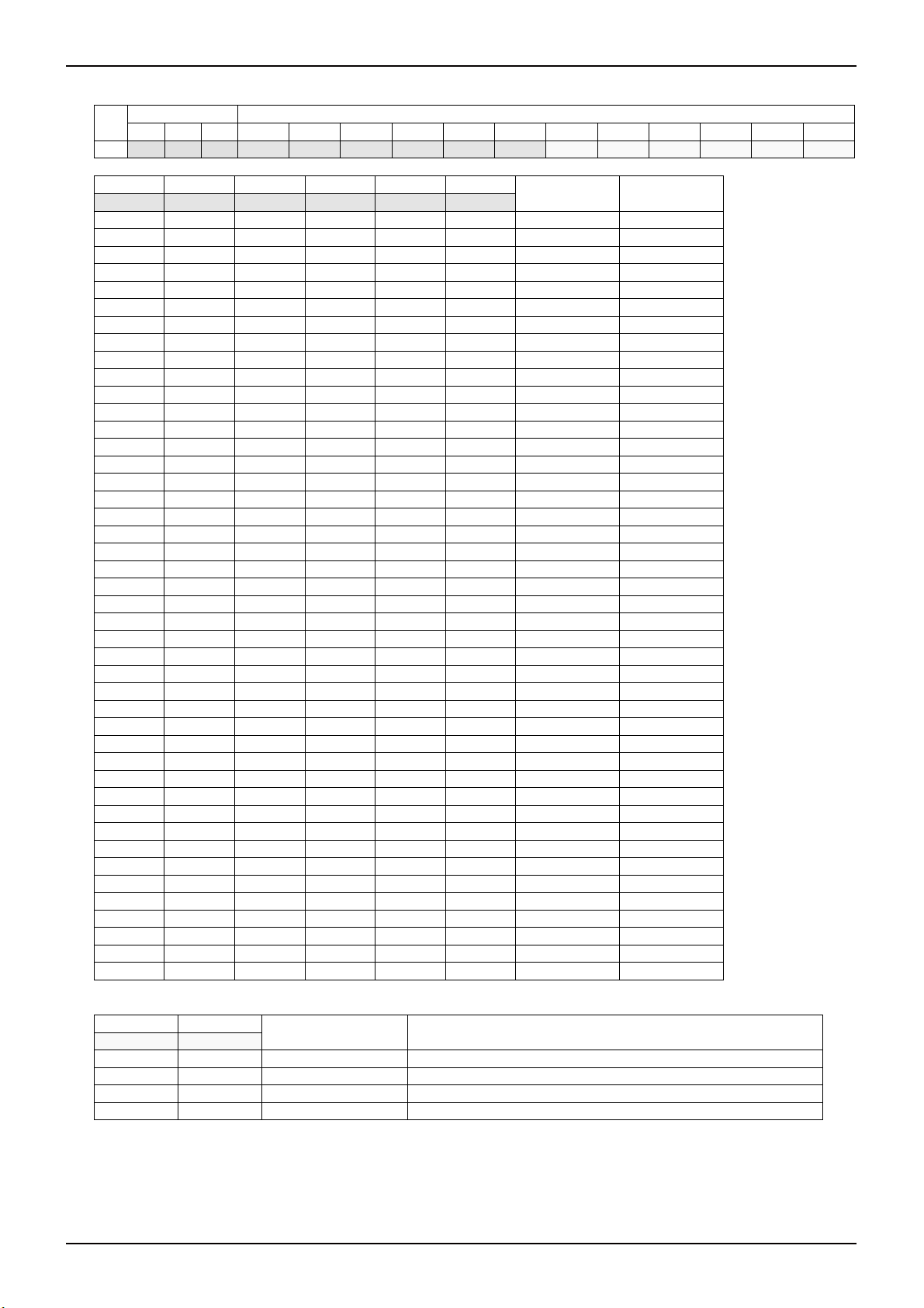
(2) Serial Register Bit Map
Bit Map is consisted of 5 addresses and 60 data. It is the prohibited bit of MODExx input. Don’t input the prohibited bit
at all times. A low level should be input to the TEST bit at all times. A high signal may cause the IC to malfunction.
(a) The Prohibited Input of MODE Bit
(MODE45, MODE34, MODE23, MODE13) = (0, 0, 0, 1), (0, 0, 1, 0), (0, 0, 1, 1), (1, 0, 0, 1), (1, 0, 1, 0), (1, 0, 1, 1),
(1, 1, 0, 0), (1, 1, 0, 1), (1, 1, 1, 0), (1, 1, 1, 1)
BD6370GUL Serial Register Bit Map
ADDRESS BIT DATA BIT
No.
Bit[E] Bit[D] Bit[C] Bit[B] Bit[A] Bit[9] Bit[8] Bit[7] Bit[6] Bit[5] Bit[4] Bit[3] Bit[2] Bit[1] Bit[0]
00H 0 0 0 TEST TEST MODE45 MODE34 MODE23 MODE13 MODE3C MODE3B MODE3A MODE12C MODE12B MODE12A
01H 0 0 1 DAC12[5] DAC12[4] D AC12[3] DAC12[2] DAC12[1] DAC12[0] MODE5B MODE5A MODE4D MODE4C MODE4B MODE4A
02H 0 1 0 DAC5[5] DAC5[4] DAC5[3] DAC5[2] DAC5[1] DAC5[0] DAC3[5] DAC3[4] DAC3[3] DAC3[2] DAC3[1] DAC3[0]
03H 0 1 1 DACV4[5] DACV4[4] DACV4[3] DACV4[2] DACV4[1] DACV4[0] DACI4[5] DACI4[4] DACI4[3] DACI4[2] DACI4[1] DACI4[0]
04H 1 0 0 TEST TEST IN5B IN5A IN4B IN4A IN3B IN3A IN2B IN2A IN1B IN1A
BD6370GUL Serial Register Bit Function
Bit Name Function Bit Name Function
MODE13 OUT1A-OUT3A resemblance drive select MODExA Control input mode select ch1 to ch5 (x=1 to 5)
MODE23 OUT2A-OUT3B resemblance drive select MODExB Control input mode select ch1 to ch5 (x=1 to 5)
MODE34 INPUT34 terminal select ch3 or ch4
MODE45 INPUT45 terminal select ch4 or ch5
MODExC
INxA Control input mode select ch1 to ch5 (x=1 to 5) MODExC
INxB Control input mode select ch1 to ch5 (x=1 to 5) MODExD
TEST TEST BIT (Low level input fixed) DACx[y]
Output drive select Constant-Voltage / Full-ON
mode ch1 to ch3 (x=1 to 3)
Output drive select Constant-Voltage /
Constant-Current / Full-ON mode ch4 (x=4)
6Bit D/A Converter output select ch1 to ch5
(x=12 to 5, y=0 to 5)
100%
0%
100%
0%
100%
0%
100%
0%
100%
0%
www.rohm.co
© 2009 ROHM Co., Ltd. All rights reserved.
12/32
2009.06 - Rev.A

BD6370GUL, BD6758MWV, BD6758KN
Technical Note
5) Serial Register Data Bit Function (BD6370GUL)
(1) ADDRESS BIT [000] Function Explanation
ADDRESS BIT DATA BIT
No.
Bit[E] Bit[D] Bit[C] Bit[B] Bit[A] Bit[9] Bit[8] Bit[7] Bit[6] Bit[5] Bit[4] Bit[3] Bit[2] Bit[1] Bit[0]
00H 0 0 0 TEST TEST MODE45 MODE34 MODE23 MODE13 MODE3C MODE3B MODE3A MODE12C MODE12B MODE12A
(a) TEST; test bit for shipment inspection
A low signal should be input to the TEST bit at all times. A high signal may cause the IC to malfunction.
(b) MODE3C and MODE12C; output drive mode select for ch1, ch2, and ch3
Bit[5] Bit[2] drive mode for OUTPUT terminal
MODE3C MODE12C ch3 ch2 ch1
0 - Full-ON - - set DAC3=6’b11_1111
1 - Constant-Voltage - -
- 0 - Full-ON Full-ON set DAC12=6’b11_1111
- 1 - Constant-Voltage Constant-Voltage
Note
(c) MODE3B, MODE3A, MODE12B, and MODE12A; control input mode select for ch3, ch2, and ch1, respectively
Refer to I/O Truth Table (p.21/32 to p.22/32) for the detail logic of MODE3B, MODE3A, MODE12B, and MODE12A.
www.rohm.co
© 2009 ROHM Co., Ltd. All rights reserved.
13/32
2009.06 - Rev.A

(
(
BD6370GUL, BD6758MWV, BD6758KN
Technical Note
(d) MODE45, MODE34; input terminal select for ch3, ch4, and ch5, and MODE23, MODE13; resemblance drive select for
ch1, ch2, and ch3
Bit[9] Bit[8] Bit[7] Bit[6] driven outputs for INPUTx terminal Note
MODE45 MODE34 MODE23 MODE13 INPUT45 INPUT34 INPUT2 INPUT1 output terminal of OPEN mode Ref No.
0 0 0 0 OUT4A-OUT4B OUT3A-OUT3B OUT2A-OUT2B OUT1A-OUT1B OUT5A, OUT5B 1
0 0 0 1 OUT4A-OUT4B OUT3B OUT2A-OUT2B OUT1A-OUT3A OUT1B, OUT5A, OUT5B 0 0 1 0 OUT4A-OUT4B OUT3A OUT2A-OUT3B OUT1A-OUT1B OUT2B, OUT5A, OUT5B 0 0 1 1 OUT4A-OUT4B don’t care OUT2A-OUT3B OUT1A-OUT3A OUT1B, OUT2B, OUT5A, OUT5B -
0 1 0 0 OUT5A-OUT5B OUT4A-OUT4B OUT2A-OUT2B OUT1A-OUT1B OUT3A, OUT3B 2
0 1 0 1 OUT5A-OUT5B OUT4A-OUT4B OUT2A-OUT2B OUT1A-OUT3A OUT1B, OUT3B 3
0 1 1 0 OUT5A-OUT5B OUT4A-OUT4B OUT2A-OUT3B OUT1A-OUT1B OUT2B, OUT3A 4
0 1 1 1 OUT5A-OUT5B OUT4A-OUT4B OUT2A-OUT3B OUT1A-OUT3A OUT1B, OUT2B 5
1 0 0 0 OUT5A-OUT5B OUT3A-OUT3B OUT2A-OUT2B OUT1A-OUT1B OUT4A, OUT4B 6
1 0 0 1 OUT5A-OUT5B OUT3B OUT2A-OUT2B OUT1A-OUT3A OUT1B, OUT4A, OUT4B 1 0 1 0 OUT5A-OUT5B OUT3A OUT2A-OUT3B OUT1A-OUT1B OUT2B, OUT4A, OUT4B 1 0 1 1 OUT5A-OUT5B don’t care OUT2A-OUT3B OUT1A-OUT3A OUT1B, OUT2B, OUT4A, OUT4B 1 1 0 0 don’t care don’t care OUT2A-OUT2B OUT1A-OUT1B OUT3A, OUT3B, OUT4A, OUT4B, OUT5A, OUT5B 1 1 0 1 don’t care don’t care OUT2A-OUT2B OUT1A-OUT3A OUT1B, OUT3B, OUT4A, OUT4B, OUT5A, OUT5B 1 1 1 0 don’t care don’t care OUT2A-OUT3B OUT1A-OUT1B OUT2B, OUT3A, OUT4A, OUT4B, OUT5A, OUT5B 1 1 1 1 don’t care don’t care OUT2A-OUT3B OUT1A-OUT3A OUT1B, OUT2B, OUT4A, OUT4B, OUT5A, OUT5B -
Gray lines are prohibition serial bit; don’t input their bits at all times
ATTENTION in the case of resemblance drive mode (MODE23=1 and/or MODE13=1)
MODE3B, MODE3A, IN3B, and IN3A bits are “don’t care”. Because OUT1A-OUT3A is driven by MODE12B, MODE12A,
IN1B, and IN1A bits, and INPUT1 terminal control. In the same condition, MODE12B, MODE12A, IN2B, and IN2A bits,
and INPUT2 terminal drive OUT2A-OUT3B. And set the serial data as DAC12 = DAC3, if not, Output high voltage is
different value between OUT1A and OUT3A, and/or OUT2A and OUT3B.
INPUT1
INPUT2
ch1
C.V./Full ON
ch2
C.V./Full ON
OUT1A
OUT1B
OUT2A
OUT2B
M
Auto
Focus
(STM)
INPUT1
ch1
C.V./Full ON
ch2
C.V./Full ON
OUT1A
OUT1B
OUT2A
OUT2B
M
INPUT34
INPUT45
ch3
C.V./Full ON
ch4
C.V./C.C./Full ON
ch5
C.C.
Fig.43 Example of Standard Model
ref No. 1, 2, and 6)
INPUT1
INPUT2
ch1
C.V./Full ON
ch2
C.V./Full ON
OUT3A
OUT3B
OUT4A
OUT4B
OUT5A
OUT5B
OUT1A
OUT1B
OUT2A
OUT2B
Zoom
(DCM)
Iris
(VCM)
Shutter
(VCM)
INPUT34
INPUT45
ch3
C.V./Full ON
ch4
C.V./C.C./Full ON
ch5
C.C.
OUT3A
OUT3B
OUT4A
OUT4B
OUT5A
OUT5B
Fig.44 Example of High Performance Model
ref No.2 and 5)
Auto
M
Focus
(STM)
INPUT1
INPUT2
ch1
C.V./Full ON
ch2
C.V./Full ON
OUT1A
OUT1B
OUT2A
OUT2B
M
M
INPUT34
INPUT45
ch3
C.V./Full ON
ch4
C.V./C.C./Full ON
ch5
C.C.
Fig.45 Example of Standard Model and 1 Actuator
(ref No.3 and 6)
OUT3A
OUT3B
OUT4A
OUT4B
OUT5A
OUT5B
Iris
(VCM)
Zoom
(DCM)
Shutter
(VCM)
other
actuator;
LED etc.
OUT3A
OUT3B
OUT4A
OUT4B
OUT5A
OUT5B
INPUT34
INPUT45
ch3
C.V./Full ON
ch4
C.V./C.C./Full ON
ch5
C.C.
Fig.46 Example of Standard Model and 1 Actuator
(ref No.4 and 6)
C.V.=Constant-Voltage drive mode, Full ON=Full-ON drive mode, and C.C.=Constant-Current drive mode
STM=Stepping Motor, DCM=DC Motor, and VCM=Voice Coil Motor
Examples of Applications above are typical. BD6370GUL is not limited to these applications.
Auto
Focus
(STM)
Iris or Zoom
(STM)
Zoom or Iris
(DCM, VCM)
Shutter
(VCM)
Auto
Focus
(STM)
Iris
(VCM)
Zoom
(DCM)
Shutter
(VCM)
other
actuator;
LED etc.
www.rohm.co
© 2009 ROHM Co., Ltd. All rights reserved.
14/32
2009.06 - Rev.A
BD6370GUL, BD6758MWV, BD6758KN
Technical Note
(2) ADDRESS BIT [001] Function Explanation
ADDRESS BIT DATA BIT
No.
Bit[E] Bit[D] Bit[C] Bit[B] Bit[A] Bit[9] Bit[8] Bit[7] Bit[6] Bit[5] Bit[4] Bit[3] Bit[2] Bit[1] Bit[0]
01H 0 0 1 DAC12[5] DAC12[4] D AC12[3] DAC12[2] DAC12[1] DAC12[0] MODE5B MODE5A MODE4D MODE4C MODE4B MODE4A
(a) DAC12[5] to DAC12[0]; D/A Converter setting for output high voltage of Constant-Voltage mode in ch1 and ch2
Bit[B] Bit[A] Bit[9] Bit[8] Bit[7] Bit[6]
DAC12[5] DAC12[4] DAC12[3] DAC12[2] DAC12[1] DAC12[0]
0 1 0 1 0 0 0.188 1.500
0 1 0 1 0 1 0.197 1.575
0 1 0 1 1 0 0.206 1.650
0 1 0 1 1 1 0.216 1.725
0 1 1 0 0 0 0.225 1.800
0 1 1 0 0 1 0.234 1.875
0 1 1 0 1 0 0.244 1.950
0 1 1 0 1 1 0.253 2.025
0 1 1 1 0 0 0.263 2.100
0 1 1 1 0 1 0.272 2.175
0 1 1 1 1 0 0.281 2.250
0 1 1 1 1 1 0.291 2.325
1 0 0 0 0 0 0.300 2.400
1 0 0 0 0 1 0.309 2.475
1 0 0 0 1 0 0.319 2.550
1 0 0 0 1 1 0.328 2.625
1 0 0 1 0 0 0.338 2.700
1 0 0 1 0 1 0.347 2.775
1 0 0 1 1 0 0.356 2.850
1 0 0 1 1 1 0.366 2.925
1 0 1 0 0 0 0.375 3.000
1 0 1 0 0 1 0.384 3.075
1 0 1 0 1 0 0.394 3.150
1 0 1 0 1 1 0.403 3.225
1 0 1 1 0 0 0.413 3.300
1 0 1 1 0 1 0.422 3.375
1 0 1 1 1 0 0.431 3.450
1 0 1 1 1 1 0.441 3.525
1 1 0 0 0 0 0.450 3.600
1 1 0 0 0 1 0.459 3.675
1 1 0 0 1 0 0.469 3.750
1 1 0 0 1 1 0.478 3.825
1 1 0 1 0 0 0.488 3.900
1 1 0 1 0 1 0.497 3.975
1 1 0 1 1 0 0.506 4.050
1 1 0 1 1 1 0.516 4.125
1 1 1 0 0 0 0.525 4.200
1 1 1 0 0 1 0.534 4.275
1 1 1 0 1 0 0.544 4.350
1 1 1 0 1 1 0.553 4.425
1 1 1 1 0 0 0.563 4.500
1 1 1 1 0 1 0.572 4.575
1 1 1 1 1 0 0.581 4.650
1 1 1 1 1 1 0.591 4.725
DAC12 setting
voltage; V
DAC12
Output high
[V]
voltage; VVOH [V]
(b) MODE4D and MODE4C; output drive mode select for ch4
Bit[3] Bit[2]
MODE4D MODE4C
0 0 Full-ON set DACV4=DACI4=6’b11_1111, and RNF4 terminal to ground
0 1 Full-ON set DACV4=DACI4=6’b11_1111, and RNF4 terminal to ground
1 0 Constant Voltage set DACI4=6’b11_1111, and RNF4 terminal to ground
1 1 Constant Current set DACV4=6’b11_1111, and RNF4 terminal with resistance to ground
drive mode for ch4 Note
(c) MODE5B, MODE5A, MODE4B, and MODE4A; control input mode select for ch5 and ch4, respectively
Refer to I/O Truth Table (p.23/32) for the detail logic of MODE5B, MODE5A, MODE4B, and MODE4A.
www.rohm.co
© 2009 ROHM Co., Ltd. All rights reserved.
15/32
2009.06 - Rev.A

BD6370GUL, BD6758MWV, BD6758KN
Technical Note
(3) ADDRESS BIT [010] Function Explanation
ADDRESS BIT DATA BIT
No.
Bit[E] Bit[D] Bit[C] Bit[B] Bit[A] Bit[9] Bit[8] Bit[7] Bit[6] Bit[5] Bit[4] Bit[3] Bit[2] Bit[1] Bit[0]
02H 0 1 0 DAC5[5] DAC5[4] DAC5[3] DAC5[2] DAC5[1] DAC5[0] DAC3[5] DAC3[4] DAC3[3] DAC3[2] DAC3[1] DAC3[0]
(a) DAC5[5] to DAC5[0]; D/A Converter setting for output current (DAC5 setting voltage) of Constant-Current mode in ch5
As regards how to calculate the output current setting, refer to p.11/32 and p.24/32
Bit[B] Bit[A] Bit[9] Bit[8] Bit[7] Bit[6]
DAC5[5] DAC5[4] DAC5[3] DAC5[2] DAC5[1] DAC5[0]
DAC5 setting
V
voltage;
DAC5
[mV]
R
=0.5Ω
RNF5
Output current [mA]
R
=1.0Ω
RNF5
Output current [mA]
0 0 1 0 1 0 50 96 49
0 0 1 0 1 1 55 105 54
0 0 1 1 0 0 60 115 59
0 0 1 1 0 1 65 125 64
0 0 1 1 1 0 70 134 68
0 0 1 1 1 1 75 144 73
0 1 0 0 0 0 80 153 78
0 1 0 0 0 1 85 163 83
0 1 0 0 1 0 90 172 88
0 1 0 0 1 1 95 182 93
0 1 0 1 0 0 100 192 98
0 1 0 1 0 1 105 201 103
0 1 0 1 1 0 110 211 108
0 1 0 1 1 1 115 220 113
0 1 1 0 0 0 120 230 117
0 1 1 0 0 1 125 239 122
0 1 1 0 1 0 130 249 127
0 1 1 0 1 1 135 259 132
0 1 1 1 0 0 140 268 137
0 1 1 1 0 1 145 278 142
0 1 1 1 1 0 150 287 147
0 1 1 1 1 1 155 297 152
1 0 0 0 0 0 160 307 157
1 0 0 0 0 1 165 316 161
1 0 0 0 1 0 170 326 166
1 0 0 0 1 1 175 336 171
1 0 0 1 0 0 180 345 176
1 0 0 1 0 1 185 355 181
1 0 0 1 1 0 190 364 186
1 0 0 1 1 1 195 374 191
1 0 1 0 0 0 200 383 196
1 0 1 0 0 1 205 393 201
1 0 1 0 1 0 210
1 0 1 0 1 1 215 210
1 0 1 1 0 0 220 216
1 0 1 1 0 1 225 220
1 0 1 1 1 0 230 225
1 0 1 1 1 1 235 230
1 1 0 0 0 0 240 235
1 1 0 0 0 1 245 240
1 1 0 0 1 0 250 245
1 1 0 0 1 1 255 250
1 1 0 1 0 0 260 254
1 1 0 1 0 1 265 259
1 1 0 1 1 0 270 264
1 1 0 1 1 1 275 269
1 1 1 0 0 0 280 274
1 1 1 0 0 1 285 279
1 1 1 0 1 0 290 284
1 1 1 0 1 1 295 289
1 1 1 1 0 0 300 294
1 1 1 1 0 1 305 298
1 1 1 1 1 0 310 303
1 1 1 1 1 1 315 308
Over Operating
Condition
205
www.rohm.co
© 2009 ROHM Co., Ltd. All rights reserved.
16/32
2009.06 - Rev.A

BD6370GUL, BD6758MWV, BD6758KN
(b) DAC3[5] to DAC3[0]; D/A Converter setting for output high voltage of Constant-Voltage mode in ch3
Bit[5] Bit[4] Bit[3] Bit[2] Bit[1] Bit[0]
DAC3[5] DAC3[4] DAC3[3] DAC3[2] DAC3[1] DAC3[0]
0 1 0 1 0 0 0.188 1.500
0 1 0 1 0 1 0.197 1.575
0 1 0 1 1 0 0.206 1.650
0 1 0 1 1 1 0.216 1.725
0 1 1 0 0 0 0.225 1.800
0 1 1 0 0 1 0.234 1.875
0 1 1 0 1 0 0.244 1.950
0 1 1 0 1 1 0.253 2.025
0 1 1 1 0 0 0.263 2.100
0 1 1 1 0 1 0.272 2.175
0 1 1 1 1 0 0.281 2.250
0 1 1 1 1 1 0.291 2.325
1 0 0 0 0 0 0.300 2.400
1 0 0 0 0 1 0.309 2.475
1 0 0 0 1 0 0.319 2.550
1 0 0 0 1 1 0.328 2.625
1 0 0 1 0 0 0.338 2.700
1 0 0 1 0 1 0.347 2.775
1 0 0 1 1 0 0.356 2.850
1 0 0 1 1 1 0.366 2.925
1 0 1 0 0 0 0.375 3.000
1 0 1 0 0 1 0.384 3.075
1 0 1 0 1 0 0.394 3.150
1 0 1 0 1 1 0.403 3.225
1 0 1 1 0 0 0.413 3.300
1 0 1 1 0 1 0.422 3.375
1 0 1 1 1 0 0.431 3.450
1 0 1 1 1 1 0.441 3.525
1 1 0 0 0 0 0.450 3.600
1 1 0 0 0 1 0.459 3.675
1 1 0 0 1 0 0.469 3.750
1 1 0 0 1 1 0.478 3.825
1 1 0 1 0 0 0.488 3.900
1 1 0 1 0 1 0.497 3.975
1 1 0 1 1 0 0.506 4.050
1 1 0 1 1 1 0.516 4.125
1 1 1 0 0 0 0.525 4.200
1 1 1 0 0 1 0.534 4.275
1 1 1 0 1 0 0.544 4.350
1 1 1 0 1 1 0.553 4.425
1 1 1 1 0 0 0.563 4.500
1 1 1 1 0 1 0.572 4.575
1 1 1 1 1 0 0.581 4.650
1 1 1 1 1 1 0.591 4.725
DAC3 setting
voltage; V
DAC3
Output high
[V]
voltage; VVOH [V]
Technical Note
www.rohm.co
© 2009 ROHM Co., Ltd. All rights reserved.
17/32
2009.06 - Rev.A

BD6370GUL, BD6758MWV, BD6758KN
Technical Note
(4) ADDRESS BIT [011] Function Explanation
ADDRESS BIT DATA BIT
No.
Bit[E] Bit[D] Bit[C] Bit[B] Bit[A] Bit[9] Bit[8] Bit[7] Bit[6] Bit[5] Bit[4] Bit[3] Bit[2] Bit[1] Bit[0]
03H 0 1 1 DACV4[5] DACV4[4] DACV4[3] DACV4[2] DACV4[1] DACV4[0] DACI4[5] DACI4[4] DACI4[3] DACI4[2] DACI4[1] DACI4[0]
(a) DACV4[5] to DACV4[0]; D/A Converter setting for output high voltage of Constant-Voltage mode in ch4
Bit[B] Bit[A] Bit[9] Bit[8] Bit[7] Bit[6]
DACV4[5] DACV4[4] DACV4[3] DACV4[2] DACV4[1] DACV4[0]
0 1 0 1 0 0 0.188 1.500
0 1 0 1 0 1 0.197 1.575
0 1 0 1 1 0 0.206 1.650
0 1 0 1 1 1 0.216 1.725
0 1 1 0 0 0 0.225 1.800
0 1 1 0 0 1 0.234 1.875
0 1 1 0 1 0 0.244 1.950
0 1 1 0 1 1 0.253 2.025
0 1 1 1 0 0 0.263 2.100
0 1 1 1 0 1 0.272 2.175
0 1 1 1 1 0 0.281 2.250
0 1 1 1 1 1 0.291 2.325
1 0 0 0 0 0 0.300 2.400
1 0 0 0 0 1 0.309 2.475
1 0 0 0 1 0 0.319 2.550
1 0 0 0 1 1 0.328 2.625
1 0 0 1 0 0 0.338 2.700
1 0 0 1 0 1 0.347 2.775
1 0 0 1 1 0 0.356 2.850
1 0 0 1 1 1 0.366 2.925
1 0 1 0 0 0 0.375 3.000
1 0 1 0 0 1 0.384 3.075
1 0 1 0 1 0 0.394 3.150
1 0 1 0 1 1 0.403 3.225
1 0 1 1 0 0 0.413 3.300
1 0 1 1 0 1 0.422 3.375
1 0 1 1 1 0 0.431 3.450
1 0 1 1 1 1 0.441 3.525
1 1 0 0 0 0 0.450 3.600
1 1 0 0 0 1 0.459 3.675
1 1 0 0 1 0 0.469 3.750
1 1 0 0 1 1 0.478 3.825
1 1 0 1 0 0 0.488 3.900
1 1 0 1 0 1 0.497 3.975
1 1 0 1 1 0 0.506 4.050
1 1 0 1 1 1 0.516 4.125
1 1 1 0 0 0 0.525 4.200
1 1 1 0 0 1 0.534 4.275
1 1 1 0 1 0 0.544 4.350
1 1 1 0 1 1 0.553 4.425
1 1 1 1 0 0 0.563 4.500
1 1 1 1 0 1 0.572 4.575
1 1 1 1 1 0 0.581 4.650
1 1 1 1 1 1 0.591 4.725
DACV4 setting
voltage; V
DACV4
Output high
[V]
voltage; VVOH [V]
www.rohm.co
© 2009 ROHM Co., Ltd. All rights reserved.
18/32
2009.06 - Rev.A

BD6370GUL, BD6758MWV, BD6758KN
Technical Note
(b) DACI4[5] to DACI4[0]; D/A Converter setting for output current (DACI4 setting voltage) of Constant-Current mode in ch4
As regards how to calculate the output current setting, refer to p.11/32 and p.24/32
Bit[5] Bit[4] Bit[3] Bit[2] Bit[1] Bit[0]
DACI4[5] DACI4[4] DACI4[3] DACI4[2] DACI4[1] DACI4[0]
DACI4 setting
voltage;
V
DACI4
[mV]
R
=0.5Ω
RNFI4
Output current [mA]
R
=1.0Ω
RNFI4
Output current [mA]
0 0 1 0 1 0 50 99 50
0 0 1 0 1 1 55 109 55
0 0 1 1 0 0 60 119 60
0 0 1 1 0 1 65 129 65
0 0 1 1 1 0 70 139 70
0 0 1 1 1 1 75 149 75
0 1 0 0 0 0 80 159 80
0 1 0 0 0 1 85 169 85
0 1 0 0 1 0 90 179 90
0 1 0 0 1 1 95 188 95
0 1 0 1 0 0 100 198 100
0 1 0 1 0 1 105 208 105
0 1 0 1 1 0 110 218 110
0 1 0 1 1 1 115 228 115
0 1 1 0 0 0 120 238 120
0 1 1 0 0 1 125 248 125
0 1 1 0 1 0 130 258 129
0 1 1 0 1 1 135 268 134
0 1 1 1 0 0 140 278 139
0 1 1 1 0 1 145 288 144
0 1 1 1 1 0 150 298 149
0 1 1 1 1 1 155 308 154
1 0 0 0 0 0 160 317 159
1 0 0 0 0 1 165 327 164
1 0 0 0 1 0 170 337 169
1 0 0 0 1 1 175 347 174
1 0 0 1 0 0 180 357 179
1 0 0 1 0 1 185 367 184
1 0 0 1 1 0 190 377 189
1 0 0 1 1 1 195 387 194
1 0 1 0 0 0 200 397 199
1 0 1 0 0 1 205
1 0 1 0 1 0 210 209
1 0 1 0 1 1 215 214
1 0 1 1 0 0 220 219
1 0 1 1 0 1 225 224
1 0 1 1 1 0 230 229
1 0 1 1 1 1 235 234
1 1 0 0 0 0 240 239
1 1 0 0 0 1 245 244
1 1 0 0 1 0 250 249
1 1 0 0 1 1 255 254
1 1 0 1 0 0 260 259
1 1 0 1 0 1 265 264
1 1 0 1 1 0 270 269
1 1 0 1 1 1 275 274
1 1 1 0 0 0 280 279
1 1 1 0 0 1 285 284
1 1 1 0 1 0 290 289
1 1 1 0 1 1 295 294
1 1 1 1 0 0 300 299
1 1 1 1 0 1 305 304
1 1 1 1 1 0 310 309
1 1 1 1 1 1 315 314
Over Operating
Condition
204
www.rohm.co
© 2009 ROHM Co., Ltd. All rights reserved.
19/32
2009.06 - Rev.A

BD6370GUL, BD6758MWV, BD6758KN
Technical Note
(5) ADDRESS BIT [100] Function Explanation
ADDRESS BIT DATA BIT
No.
Bit[E] Bit[D] Bit[C] Bit[B] Bit[A] Bit[9] Bit[8] Bit[7] Bit[6] Bit[5] Bit[4] Bit[3] Bit[2] Bit[1] Bit[0]
04H 1 0 0 TEST TEST IN5B IN5A IN4B IN4A IN3B IN3A IN2B IN2A IN1B IN1A
(a) TEST; test bit for shipment inspection
A low signal should be input to the TEST bit at all times. A high signal may cause the IC to malfunction.
(b) IN5B to IN1A; control input mode select for ch1 to ch5, respectively
Refer to I/O Truth Table (p.21/32 to p.23/32) for the detail logic of IN1A to IN5B.
www.rohm.co
© 2009 ROHM Co., Ltd. All rights reserved.
20/32
2009.06 - Rev.A

BD6370GUL, BD6758MWV, BD6758KN
6) I/O Truth Table (BD6370GUL)
(1) I/O truth table for ch1 and ch2, in the case of MODE13=0, MODE23=0 (x=1 or 2)
Serial interface input bit Terminal Output terminal
MODE12B MODE12A INxB INxA INPUTx OUTxA OUTxB
PWM Drive Mode by INPUTx terminal
0 0 0 0 X Z Z OFF
0 0 0 1 L L L Brake
0 0 0 1 H H L CW
0 0 1 0 L L L Brake
0 0 1 0 H L H CCW
0 0 1 1 X L L Brake
PWM Drive Mode by INPUTx terminal
0 1 0 0 X Z Z OFF
0 1 0 1 L H L CW
0 1 0 1 H L L Brake
0 1 1 0 L L H CCW
0 1 1 0 H L L Brake
0 1 1 1 X L L Brake
CW / CCW Drive Mode by INPUTx terminal
1 0 X 0 X Z Z OFF
1 0 0 1 L L H CCW
1 0 0 1 H H L CW
1 0 1 1 X L L Brake
CW / CCW Drive Mode by INPUTx terminal
1 1 X 0 X Z Z OFF
1 1 0 1 L H L CW
1 1 0 1 H L H CCW
1 1 1 1 X L L Brake
H; High level, L; Low level, Z; Hi impedance, X; Don’t care
At CW, current flows from OUTxA to OUTxB. At CCW, current flows from OUTxB to OUTxA.
(2) I/O truth table for ch3, in the case of MODE34=0, MODE13=0, and MODE23=0
Serial interface input bit Terminal Output terminal
MODE3B MODE3A IN3B IN3A INPUT34 OUT3A OUT3B
PWM Drive Mode by INPUT34 terminal
0 0 0 0 X Z Z OFF
0 0 0 1 L L L Brake
0 0 0 1 H H L CW
0 0 1 0 L L L Brake
0 0 1 0 H L H CCW
0 0 1 1 X L L Brake
PWM Drive Mode by INPUT34 terminal
0 1 0 0 X Z Z OFF
0 1 0 1 L H L CW
0 1 0 1 H L L Brake
0 1 1 0 L L H CCW
0 1 1 0 H L L Brake
0 1 1 1 X L L Brake
CW / CCW Drive Mode by INPUT34 terminal
1 0 X 0 X Z Z OFF
1 0 0 1 L L H CCW
1 0 0 1 H H L CW
1 0 1 1 X L L Brake
CW / CCW Drive Mode by INPUT34 terminal
1 1 X 0 X Z Z OFF
1 1 0 1 L H L CW
1 1 0 1 H L H CCW
1 1 1 1 X L L Brake
H; High level, L; Low level, Z; Hi impedance, X; Don’t care
At CW, current flows from OUT3A to OUT3B. At CCW, current flows from OUT3B to OUT3A.
Technical Note
MODE
MODE
www.rohm.co
© 2009 ROHM Co., Ltd. All rights reserved.
21/32
2009.06 - Rev.A

A
A
A
A
A
BD6370GUL, BD6758MWV, BD6758KN
(3) I/O truth table for ch1, ch3, in the case of MODE13=1 (OUT1A-OUT3A resemblance drive mode)
Serial interface input bit Terminal Output terminal
MODE12B MODE12A IN1B IN1
PWM Drive Mode by INPUT1 terminal
0 0 0 0 X Z Z OFF
0 0 0 1 L L L Brake
0 0 0 1 H H L CW
0 0 1 0 L L L Brake
0 0 1 0 H L H CCW
0 0 1 1 X L L Brake
PWM Drive Mode by INPUT1 terminal
0 1 0 0 X Z Z OFF
0 1 0 1 L H L CW
0 1 0 1 H L L Brake
0 1 1 0 L L H CCW
0 1 1 0 H L L Brake
0 1 1 1 X L L Brake
CW / CCW Drive Mode by INPUT1 terminal
1 0 X 0 X Z Z OFF
1 0 0 1 L L H CCW
1 0 0 1 H H L CW
1 0 1 1 X L L Brake
CW / CCW Drive Mode by INPUT1 terminal
1 1 X 0 X Z Z OFF
1 1 0 1 L H L CW
1 1 0 1 H L H CCW
1 1 1 1 X L L Brake
H; High level, L; Low level, Z; Hi impedance, X; Don’t care, OUT1B; Hi impedance
At CW, current flows from OUT1A to OUT3A. At CCW, current flows from OUT3A to OUT1A.
INPUT1 OUT1
OUT3
MODE
(4) I/O truth table for ch2, ch3, in the case of MODE23=1 (OUT2A-OUT3B resemblance drive mode)
Serial interface input bit Terminal Output terminal
MODE12B MODE12A IN2B IN2
PWM Drive Mode by INPUT2 terminal
0 0 0 0 X Z Z OFF
0 0 0 1 L L L Brake
0 0 0 1 H H L CW
0 0 1 0 L L L Brake
0 0 1 0 H L H CCW
0 0 1 1 X L L Brake
PWM Drive Mode by INPUT2 terminal
0 1 0 0 X Z Z OFF
0 1 0 1 L H L CW
0 1 0 1 H L L Brake
0 1 1 0 L L H CCW
0 1 1 0 H L L Brake
0 1 1 1 X L L Brake
CW / CCW Drive Mode by INPUT2 terminal
1 0 X 0 X Z Z OFF
1 0 0 1 L L H CCW
1 0 0 1 H H L CW
1 0 1 1 X L L Brake
CW / CCW Drive Mode by INPUT2 terminal
1 1 X 0 X Z Z OFF
1 1 0 1 L H L CW
1 1 0 1 H L H CCW
1 1 1 1 X L L Brake
H; High level, L; Low level, Z; Hi impedance, X; Don’t care, OUT2B; Hi impedance
At CW, current flows from OUT2A to OUT3B. At CCW, current flows from OUT3B to OUT2A.
INPUT2 OUT2
OUT3B
MODE
ATTENTION in the case of resemblance drive mode (MODE23=1 and/or MODE13=1)
MODE3B, MODE3A, IN3B, and IN3A bits are “don’t care”. Because OUT1A-OUT3A is driven by MODE12B, MODE12A,
IN1B, and IN1A bits, and INPUT1 terminal control. In the same condition, MODE12B, MODE12A, IN2B, and IN2A bits,
and INPUT2 terminal drive OUT2A-OUT3B. And set the serial data as DAC12 = DAC3, if not, Output high voltage is
different value between OUT1A and OUT3A, and/or OUT2A and OUT3B.
Technical Note
www.rohm.co
© 2009 ROHM Co., Ltd. All rights reserved.
22/32
2009.06 - Rev.A

BD6370GUL, BD6758MWV, BD6758KN
(5) I/O truth table for ch4, in the case of MODE45=0 (if MODE34=0, then x=45, else then x=34)
Serial interface input bit Terminal Output terminal
MODE4B MODE4A IN4B IN4A INPUTx OUT4A OUT4B
PWM Drive Mode by INPUTx terminal
0 0 0 0 X Z Z OFF
0 0 0 1 L L L Brake
0 0 0 1 H H L CW
0 0 1 0 L L L Brake
0 0 1 0 H L H CCW
0 0 1 1 X L L Brake
PWM Drive Mode by INPUTx terminal
0 1 0 0 X Z Z OFF
0 1 0 1 L H L CW
0 1 0 1 H L L Brake
0 1 1 0 L L H CCW
0 1 1 0 H L L Brake
0 1 1 1 X L L Brake
CW / CCW Drive Mode by INPUTx terminal
1 0 X 0 X Z Z OFF
1 0 0 1 L L H CCW
1 0 0 1 H H L CW
1 0 1 1 X L L Brake
CW / CCW Drive Mode by INPUTx terminal
1 1 X 0 X Z Z OFF
1 1 0 1 L H L CW
1 1 0 1 H L H CCW
1 1 1 1 X L L Brake
H; High level, L; Low level, Z; Hi impedance, X; Don’t care
At CW, current flows from OUT4A to OUT4B. At CCW, current flows from OUT4B to OUT4A.
(6) I/O truth table for ch5, in the case of MODE45=1, MODE34=0 (or MODE45=0, MODE34=1)
Serial interface input bit Terminal Output terminal
MODE5B MODE5A IN5B IN5A INPUT45 OUT5A OUT5B
PWM Drive Mode by INPUT45 terminal
0 0 0 0 X Z Z OFF
0 0 0 1 L L L Brake
0 0 0 1 H H L CW
0 0 1 0 L L L Brake
0 0 1 0 H L H CCW
0 0 1 1 X L L Brake
PWM Drive Mode by INPUT45 terminal
0 1 0 0 X Z Z OFF
0 1 0 1 L H L CW
0 1 0 1 H L L Brake
0 1 1 0 L L H CCW
0 1 1 0 H L L Brake
0 1 1 1 X L L Brake
CW / CCW Drive Mode by INPUT45 terminal
1 0 X 0 X Z Z OFF
1 0 0 1 L L H CCW
1 0 0 1 H H L CW
1 0 1 1 X L L Brake
CW / CCW Drive Mode by INPUT45 terminal
1 1 X 0 X Z Z OFF
1 1 0 1 L H L CW
1 1 0 1 H L H CCW
1 1 1 1 X L L Brake
H; High level, L; Low level, Z; Hi impedance, X; Don’t care
At CW, current flows from OUT5A to OUT5B. At CCW, current flows from OUT5B to OUT5A.
Technical Note
MODE
MODE
www.rohm.co
© 2009 ROHM Co., Ltd. All rights reserved.
23/32
2009.06 - Rev.A

A2B1A
D1E1
A
BD6370GUL, BD6758MWV, BD6758KN
Technical Note
7) The More Precise Constant-Current Settings (BD6370GUL)
Regarding Constant-Current Drive blocks (ch4 and ch5), there is the metal impedance of each RNF in BD6370GUL inside:
4mΩ (Typ.) and 22mΩ (Typ.), respectively. Then the metal impedances and the board patterning impedances of RNF4 and
RNF5 lines considered, set each D/A Converter to drive the actuator in the more precise constant current.
BD6370GUL
Constant Current Drive block (ch4 and ch5)
Le vel Shif t
&
Pre D riv er
6bit DAC
Le vel Shif t
&
Pre D riv er
6bit DAC
VDACI4
I4
V
DAC5
5
H bridge
C.V./C.C./Full ON
METALI4
R
=4mΩ (Typ.)
H bridge
C.C.
R
METAL5
=22mΩ (Typ. )
1~1 00u F
Board Ground
VM
3
OUT4 A
OUT4 B
RNF4
1
OUT5 A
C1
OUT5 B
RNF5
IOUT4
R
R
W4_1
W5_1
I
OUT5
R
R
RNFI4
RNF5
R
W4_2
R
W5_2
R
; external component of output current detection
RNFx
R
; metal impedance of BD6370 GUL’s inside
METALx
; board patterning impedance
R
Wx_1, 2
V
; setting value of constan t current
DACx
; current flowed through the motor
I
OUT x
Fig.47 Metal Impedance and Board Patterning Impedance of Constant-Current block
The more correct D/A Converter settings of Constant-Current H-bridge (ch4 and ch5)
Output current value; I
OUTx
[A] = V
DACx
[V]÷(R
RNFx
[Ω]+R
METALx
[Ω]+R
Wx_1
[Ω]+R
Wx_2
[Ω])
(ex.) If there are V
Output current value (ch4); I
Output current value (ch5); I
Else if there are V
=0.1[V], R
DACx
=0.1[V], R
DACx
=0.5[Ω], and R
RNFx
OUT4
OUT5
RNFx
Wx_1+RWx_2
=0[Ω] (the ideal patterning condition), then
[A] = 0.1[V]÷(0.5[Ω]+0.004[Ω]+0[Ω]) = 0.198
[A] = 0.1[V]÷(0.5[Ω]+0.022[Ω]+0[Ω]) = 0.191
= 0.5[Ω], and R
Wx_1+RWx_2
=0.05[Ω] (the more closely real patterning
condition; the value is different to the patterning), then
Output current value (ch4); I
Output current value (ch5); I
[A] = 0.1[V]÷(0.5[Ω]+0.004[Ω]+0.05[Ω]) = 0.181
OUT4
[A] = 0.1[V]÷(0.5[Ω]+0.022[Ω]+0.05[Ω]) = 0.175
OUT5
www.rohm.co
© 2009 ROHM Co., Ltd. All rights reserved.
24/32
2009.06 - Rev.A

BD6370GUL, BD6758MWV, BD6758KN
8) Application control sequences (BD6370GUL)
(1) Stepping Motor drive controlled by 2 phases mode
VCC
PS
STROBE
SCLK
SDATA
INPUT1
(i) (ii) (iii) (iv) (v) (vi) (vii)
INPUT2
OUT1A [V]
OUT1B [V]
OUT2A [V]
OUT2B [V]
OUT1A-1B [A]
OUT2A-2B [A]
; Hi impedance ; Don’t care
1 1
3 2
4
Forward Reverse
4 4
Fig.48 Timing Chart of Stepping Motor Drive
Sequence of Stepping Motor Drive
Serial interface input bit Terminal Output terminal MODE
MODE
MODE
12B
Control standby
1 0 0 0 0 0 X X Z Z Z Z
Start 2 phase mode driving
1 0 0 1 0 1 H H H L H L CW CW 1
1 0 0 1 0 1 H L H L L H CW CCW 2
1 0 0 1 0 1 L L L H L H CCW CCW 3
1 0 0 1 0 1 L H L H H L CCW CW 4
1 0 0 1 0 1 H H H L H L CW CW 1
1 0 0 1 0 1 H H H L H L CW CW 1
1 0 0 1 0 1 L H L H H L CCW CW 4
1 0 0 1 0 1 L L L H L H CCW CCW 3
1 0 0 1 0 1 H L H L L H CW CCW 2
1 0 0 1 0 1 H H H L H L CW CW 1
End timing (control standby)
1 0 0 0 0 0 X X Z Z Z Z
H; High level, L; Low level, Z; Hi impedance, X; Don’t care
At CW, current flows from OUTxA to OUTxB. At CCW, current flows from OUTxB to OUTxA.
At Forward; position up from “1” to “4”. At Reverse; position down from “4” to “1”.
IN2B IN2A IN1B IN1A INPUT1 INPUT2 OUT1A OUT1B OUT2A OUT2B ch1 ch2 Position
12A
Technical Note
3 2 1 3 4 2 1 3 2 1
Forward
Reverse
100%
0%
100%
0%
100%
0%
100%
0%
100%
0%
100%
0%
100%
0%
0%
100%
0%
100%
0%
100%
0%
100%
0%
100%
0%
-100%
100%
0%
-100%
www.rohm.co
© 2009 ROHM Co., Ltd. All rights reserved.
25/32
2009.06 - Rev.A

1
3
4
2
F
r
R
BD6370GUL, BD6758MWV, BD6758KN
In Fig.49, it shows minimum step angle, and the relation between size and direction of the current to motor.
CW
OUT2A
orwa
OUT1B
CCW
OUT1A
CW
evers
Fig.49 Torque Vector of 2 Phases Mode
OUT2B
CCW
Serial Control Input from Initial Set Up (i) to End Timing (vii)
ADDRESS BIT DATA BIT
No.
Bit[E] Bit[D] Bit[C] Bit[B] Bit[A] Bit[9] Bit[8] Bit[7] Bit[6] Bit[5] Bit[4] Bit[3] Bit[2] Bit[1] Bit[0]
Initial set up
(i) ADDRESS BIT [000]; set ch1 and ch2; Constant-Voltage drive mode
00H 0 0 0
TEST TEST MODE45 MODE34 MODE23 MODE13 MODE3C MODE3B MODE3A MODE12C MODE12B MODE12A
0 0 0 0 0 0 0 0 0 1 1 0
(ii) ADDRESS BIT [001]; set Output high voltage=3.0V for ch1 and ch2
01H 0 0 1
DAC12[5] DAC12[4] D AC12[3] DAC12[2] DAC12[1] DAC12[0] MODE5B MODE5A MODE4D MODE4C MODE4B MODE4A
1 0 1 0 0 0 0 0 0 0 0 0
(iii) ADDRESS BIT [010]; in this case, don’t care
02H 0 1 0
DAC5[5] DAC5[4] DAC5[3] DAC5[2] DAC5[1] DAC5[0] DAC3[5] DAC3[4] DAC3[3] DAC3[2] DAC3[1] DAC3[0]
0 0 0 0 0 0 0 0 0 0 0 0
(iv) ADDRESS BIT [011]; in this case, don’t care
03H 0 1 1
DACV4[5] DACV4[4] DACV4[3] DACV4[2] DACV4[1] DACV4[0] DACI4[5] DACI4[4] DACI4[3] DACI4[2] DACI4[1] DACI4[0]
0 0 0 0 0 0 0 0 0 0 0 0
(v) ADDRESS BIT [100]; set control standby mode
04H 1 0 0
TEST TEST IN5B IN5A IN4B IN4A IN3B IN3A IN2B IN2A IN1B IN1A
0 0 0 0 0 0 0 0 0 0 0 0
Start timing
(vi) ADDRESS BIT [100]
04H 1 0 0
TEST TEST IN5B IN5A IN4B IN4A IN3B IN3A IN2B IN2A IN1B IN1A
0 0 0 0 0 0 0 0 0 1 0 1
End timing
(vii) ADDRESS BIT [100]
04H 1 0 0
TEST TEST IN5B IN5A IN4B IN4A IN3B IN3A IN2B IN2A IN1B IN1A
0 0 0 0 0 0 0 0 0 0 0 0
The above Sequence is one example. BD6370GUL is not limited to this sequence.
Technical Note
www.rohm.co
© 2009 ROHM Co., Ltd. All rights reserved.
26/32
2009.06 - Rev.A

BD6370GUL, BD6758MWV, BD6758KN
●BD6758MWV and BD6758KN Function Explanation
Power-saving (p.27/32)
H : Active
L : Standby
Bypass filter Capacitor for
power supply input. (p.29/32)
1~100uF
PS
35
36
1
2
3
28
Power Save
Logic12
Logic12
Motor control input
(p.27/32)
Drive mode selection
(p.27/32)
H : EN/IN
L : IN/IN
IN1A
IN1B
IN2A
IN2B
SEL1
TSD & UVLO
Level Shift
Motor control input
(p.27/32)
Drive mode selection
(p.27/32)
H : EN/IN
L : IN/IN
Motor control input
モータ制御入力
brake function
ブレーキ機能(p.?/32)
(p.27/32)
H : ブレーキ
H : Brake
Motor control input
(p.27/32)
IN3A
IN3B
IN4A
IN4B
SEL2
BRK1
BRK2
EN1
IN5
6
7
8
9
18
10
11
27
26
Logic34
Logic5
Level Shift
Level Shift
When using the VREF voltage ( 1.2V)
resistance division value as VLIM input
value, select R
and R2 values such that,
1
≦20kΩ (p.28/32)
2kΩ≦R
1+R2
Fig.50 BD6758MWV / KN Application Circuit Diagram
VREF
1) Power-saving function (BD6758MWV / KN)
When Low-level voltage is applied to PS pin, the IC will be turned off internally and the circuit current will be 0μA (Typ.).
During operating mode, PS pin should be High-level. (See the Electrical Characteristics; p.6/32)
2) Control input (BD6758MWV / KN)
(1) INxA, INxB, EN1 and IN5 pins
These pins are used to program and control the motor drive modes. (See the Electrical Characteristics; p.6/32 and I/O
Truth Table; p.28/32)
(2) SELx pins
When the Low-level voltage is applied to the SEL pin, the I/O logic can be set to EN/IN mode. However, when the
High-level voltage is applied, the I/O logic can be set to IN/IN mode. (See the Electrical Characteristics; p.6/32 and I/O
Truth Table; p.28/32)
(3) BRKx pins
Applying the High-level voltage to the BRKx pin will set the brake mode. (See the Electrical Characteristics; p.6/32
and I/O Truth Table; p.28/32)
3) H-bridge (BD6758MWV / KN)
The 5-channel H-bridges can be controlled independently. For this reason, it is possible to drive the H-bridges
simultaneously, as long as the package thermal tolerances are not exceeded.
The H-bridge output transistors of BD6758MWV and BD6758KN are Power CMOS Drivers. The total H-bridge
ON-Resistance on the high and low sides varies with the VM voltage. The system must be designed so that the maximum
H-bridge current for each channel is 800mA or below. (See the Operating Conditions; p.2/32)
&
Pre Driver
&
Pre Driver
&
Pre Driver
VREF
20
VCC
4
19
VLIM
R1 R2
BandGap
H bridge
Full ON
H bridge
Full ON
H bridge
Full ON
H bridge
Full ON
H bridge
Const. Current
5
GND
Technical Note
Bypass filter Capacitor for
power supply input. (p.29/32)
1~100uF
31
VM1
29
30
33
34
32
14
12
13
16
17
15
24
21
25
23
22
OUT1A
OUT1B
OUT2A
OUT2B
PGND1
VM2
OUT3A
OUT3B
OUT4A
OUT4B
PGND2
VM3
OUT5A
OUT5B
RNF
SENSE
M
Bypass filter Capacitor for
power supply input. (p.29/32)
1~100uF
M
Bypass filter Capacitor for
power supply input. (p.29/32)
1~100uF
0.1Ω~5.0Ω
The output current is converted to a voltage with
the RNF external resistor and transmitted to the
SENSE pin. (p.28/32)
Iout[A] = VLIM[V]÷RNF[Ω]
www.rohm.co
© 2009 ROHM Co., Ltd. All rights reserved.
27/32
2009.06 - Rev.A

BD6370GUL, BD6758MWV, BD6758KN
4) Drive system of Linear Constant-Current H-bridge (BD6758MWV / KN: ch5)
BD6758MWV / KN (ch5) enable Linear Constant-Current Driving.
(1) Reference voltage output (with a tolerance of ±3%)
The VREF pin outputs 1.2V, based on the internal reference voltage. The output current of the Constant-Current Drive
block is controllable by connecting external resistance to the VREF pin of the IC and applying a voltage divided by the
resistor to the output current setting pins (VLIM pin). It is recommended to set the external resistance to 2kΩ or above
in consideration of the current capacity of the VREF pin, and 20kΩ or below in order to minimize the fluctuation of the
set value caused by the base current of the internal transistor of the IC.
(2) Output current detection and current settings
By connecting external resistor (0.1Ω to 5.0Ω) to the RNF pin of the IC, the motor drive current will be converted into
voltage in order to be detected. The output current is kept constant by shorting the RNF and SENSE pins and
comparing the voltage with the VLIM voltage. To perform output current settings more precisely, trim the external RNF
resistance if needed, and supply a precise voltage externally to the VLIM pin of the IC. In that case, open the VREF
pin.
Output current value
VLIM[V]
RNF[Ω]
The output current is 400mA3% if 0.2V is applied to the VLIM pin and a 0.5Ω resistor is connected externally to the
RNF pin.
If the VLIM pin is shorted to the VCC pin (or the same voltage level as the VCC is applied) and the SENSE and RNF
pins are shorted to the ground, this channel can be used as a Full-ON Drive H-bridge like the other four channels of
BD6758KN.
5) I/O truth table (BD6758MWV / KN)
BD6758MWV / KN Full-ON Driver ch1 and ch2 I/O Truth Table
Drive
mode
SEL1 INxA INxB OUTxA OUTxB
INPUT OUTPUT
H X Z Z Standby
EN/IN L
L L H L CW
L H L H CCW
L L Z Z Standby
IN/IN H
H L H L CW
L H L H CCW
H H L L Brake
L: Low, H: High, X: Don’t care, Z: High impedance
At CW, current flows from OUTA to OUTB. At CCW, current flows from OUTB to OUTA.
BD6758MWV / KN Full-ON Driver ch3 and ch4 I/O Truth Table
Drive
mode
SEL2 INxA INxB BRKx OUTxA OUTxB
INPUT OUTPUT
H X X Z Z Standby
EN/IN L
L L L H L CW
L H L L H CCW
L X H L L Brake
L L X Z Z Standby
IN/IN H
H L X H L CW
L H X L H CCW
H H X L L Brake
L: Low, H: High, X: Don’t care, Z: High impedance
At CW, current flows from OUTA to OUTB. At CCW, current flows from OUTB to OUTA.
BD6758MWV / KN Linear Constant-Current Driver ch5 I/O Truth Table
Drive
mode
EN1 IN5 OUT5A OUT5B
INPUT OUTPUT
H X Z Z Standby
EN/IN
L L H L CW
L H L H CCW
L: Low, H: High, X: Don’t care, Z: High impedance
At CW, current flows from OUTA to OUTB. At CCW, current flows from OUTB to OUTA.
Technical Note
Output mode
Output mode
Output mode
www.rohm.co
© 2009 ROHM Co., Ltd. All rights reserved.
28/32
2009.06 - Rev.A

BD6370GUL, BD6758MWV, BD6758KN
Technical Note
●I/O Circuit Diagram
PS, INPUT1, 2, 34, 45
STROBE, SCLK, SDATA
8
※
,
9
※
VM, GND,
OUT1A, 1B, 2A, 2B, 3A, 3B
VM, RNF4, OUT4A, 4B VM, RNF5, OUT5A, 5B
VCC
10kΩ
100kΩ
200kΩ
VCC
※
※
VM
20kΩ 140kΩ
8
9
OUTxA
OUTxB
PGND
20kΩ 140kΩ
4mΩ
VM
OUT4A
OUT4B
RNF4
Fig.51 BD6370GUL I/O Circuit Diagram (Resistance values are typical ones)
PS, INxA, INxB, EN1, IN5, SELx,
BRKx
VCC
VCC
VMx, OUTxA, OUTxB, PGNDx, RNF VLIM, SENSE
VMx
VREF
VCC VCC
VCC
10kΩ
OUTxA
100kΩ
OUTxB
PGNDx
RNF
200kΩ
Fig.52 BD6758MWV / KN I/O Circuit Diagram (Resistance values are typical ones)
●Notes for use
1) Absolute maximum ratings
Use of the IC in excess of absolute maximum ratings such as the applied voltage or operating temperature range may
result in IC damage. Assumptions should not be made regarding the state of the IC (short mode or open mode) when such
damage is suffered. The implementation of a physical safety measure such as a fuse should be considered when use of
the IC in a special mode where the absolute maximum ratings may be exceeded is anticipated.
2) Storage temperature range
As long as the IC is kept within this range, there should be no problems in the IC’s performance. Conversely, extreme
temperature changes may result in poor IC performance, even if the changes are within the above range.
3) Power supply pins and lines
None of the VM line for the H-bridges is internally connected to the VCC power supply line, which is only for the control logic or
analog circuit. Therefore, the VM and VCC lines can be driven at different voltages. Although these lines can be connected to a
common power supply, do not open the power supply pin but connect it to the power supply externally.
Regenerated current may flow as a result of the motor's back electromotive force. Insert capacitors between the power supply
and ground pins to serve as a route for regenerated current. Determine the capacitance in full consideration of all the
characteristics of the electrolytic capacitor, because the electrolytic capacitor may loose some capacitance at low temperatures.
If the connected power supply does not have sufficient current absorption capacity, regenerative current will cause the voltage
on the power supply line to rise, which combined with the product and its peripheral circuitry may exceed the absolute maximum
ratings. It is recommended to implement a physical safety measure such as the insertion of a voltage clamp diode between the
power supply and ground pins.
For this IC with several power supplies and a part consists of the CMOS block, it is possible that rush current may flow
instantaneously due to the internal powering sequence and delays, and to the unstable internal logic, respectively. Therefore,
give special consideration to power coupling capacitance, width of power and ground wirings, and routing of wiring.
4) Ground pins and lines
Ensure a minimum GND pin potential in all operating conditions. Make sure that no pins are at a voltage below the GND at
any time, regardless of whether it is a transient signal or not.
When using both small signal GND and large current MGND patterns, it is recommended to isolate the two ground
patterns, placing a single ground point at the application's reference point so that the pattern wiring resistance and voltage
variations caused by large currents do not cause variations in the small signal ground voltage. Be careful not to change the
GND wiring pattern of any external components, either.
The power supply and ground lines must be as short and thick as possible to reduce line impedance.
5) Thermal design
Use a thermal design that allows for a sufficient margin in light of the power dissipation (Pd) in actual operating conditions.
22mΩ
1kΩ
VM
OUT5A
OUT5B
RNF5
www.rohm.co
© 2009 ROHM Co., Ltd. All rights reserved.
29/32
2009.06 - Rev.A

BD6370GUL, BD6758MWV, BD6758KN
Technical Note
6) Pin short and wrong direction assembly of the device
Use caution when positioning the IC for mounting on printed circuit boards. The IC may be damaged if there is any
connection error or if positive and ground power supply terminals are reversed. The IC may also be damaged if pins are
shorted together or are shorted to other circuit’s power lines.
7) Actions in strong magnetic field
Use caution when using the IC in the presence of a strong magnetic field as doing so may cause the IC to malfunction.
8) ASO
When using the IC, set the output transistor for the motor so that it does not exceed absolute maximum ratings or ASO.
9) Thermal shutdown circuit
If the junction temperature (Tjmax) reaches 175°C, the TSD circuit will operate, and the coil output circuit of the motor will
open. There is a temperature hysteresis of approximately 25°C (BD6373GW and BD6873KN Typ.) and 25°C (BD6753KV
Typ.). The TSD circuit is designed only to shut off the IC in order to prevent runaway thermal operation. It is not designed
to protect the IC or guarantee its operation. The performance of the IC’s characteristics is not guaranteed and it is
recommended that the device is replaced after the TSD is activated.
10) Serial data input
In the BD6370GUL, SDATA input string start with MSB first. A low level should be input to the TEST bit at all times. A high signal
may cause the IC to malfunction. The serial settings are reset during standby mode operation and whenever the UVLO or TSD
circuits are operating.
It is the prohibited bit of MODExx input. Don’t input the prohibited bit at all times. (See the Serial Register Bit Map; p.12/32)
In the case of the resemblance drive mode (MODE13=1 and/or MODE23=1), MODE3B, MODE3A, IN3B, and IN3A bits are
“don’t care”. Because OUT1A-OUT3A is driven by MODE12B, MODE12A, IN1B, and IN1A bits, and INPUT1 terminal control. In
the same condition, MODE12B, MODE12A, IN2B, and IN2A bits, and INPUT2 terminal drive OUT2A-OUT3B. And set the serial
data as DAC12 = DAC3, if not, Output high voltage is different value between OUT1A and OUT3A, and/or OUT2A and OUT3B.
In the case of Full-ON mode for ch1 to ch3,input serial data of each Constant-Voltage setting D/A Converter (DAC12 and DAC3)
to be full bits high.
In the ch4, as it set Constant-Voltage mode, input serial data of Constant-Current setting D/A Converter (DACI4) to be full bits
high. As it set Constant-Current mode, input serial data of Constant-Voltage setting D/A Converter (DACV4) to be full bits high,
while as it set Full-ON mode, input serial data of both D/A Converters to be full bits high. In the settings of Constant-Voltage or
Full-ON mode, no need to connect the external resistance for output current detection in RNF4 pin.
11) Power saving terminal
Be cancelled power saving mode after turned on power supply VCC and VM, because of PS terminal combines power
saving with serial reset function. If the case of power saving terminal always shorted power supply terminal, reset function
may not be well, and it may cause the IC to malfunction.
12) Testing on application board
When testing the IC on an application board, connecting a capacitor to a pin with low impedance subjects the IC to stress.
Always discharge capacitors after each process or step. Always turn the IC's power supply off before connecting it to, or
removing it from a jig or fixture, during the inspection process. Ground the IC during assembly steps as an antistatic
measure. Use similar precaution when transporting and storing the IC.
13) Application example
The application circuit is recommended for use. Make sure to confirm the adequacy of the characteristics. When using the
circuit with changes to the external circuit constants, make sure to leave an adequate margin for external components
including static and transitional characteristics as well as dispersion of the IC.
14) Regarding input pin of the IC
This monolithic IC contains P
+
isolation and P substrate layers between adjacent elements to keep them isolated. P-N
junctions are formed at the intersection of these P layers with the N layers of other elements, creating a parasitic diode or
transistor. For example, the relation between each potential is as follows:
When GND > Pin A, the P-N junction operates as a parasitic diode.
When GND > Pin B, the P-N junction operates as a parasitic diode and transistor.
Parasitic elements can occur inevitably in the structure of the IC. The operation of parasitic elements can result in mutual
interference among circuits, operational faults, or physical damage. Accordingly, methods by which parasitic elements
operate, such as applying a voltage that is lower than the GND (P substrate) voltage to an input pin, should not be used.
Pin A
N
+
P
P
P
Parasitic element
GND
Resistor Transistor (NPN)
Pin A
+
N N
P substrate
Parasitic
element
Pin B
N
+
P
Parasitic element
B
C
N
E
P
GND
+
P
N
P substrate
GND
Pin B
B C
Other adjacent
elements
E
GND
Fig.53 Example of Simple IC Architecture
Parasitic
element
www.rohm.co
© 2009 ROHM Co., Ltd. All rights reserved.
30/32
2009.06 - Rev.A

V
BD6370GUL, BD6758MWV, BD6758KN
●Ordering part number
B D 6 3 7 0 G U L - E 2
Part No. Part No.
CSP50L2 (BD6360GUL)
UQFN036V5050
5.0± 0.1
1.0MAX
0.08 S
C0.2
36
28
0.5± 0.1
1PIN MARK
1
27 19
0.9
6370 :C.V./F.ON 3ch
+C.V./C.C./F.ON 1ch
+C.C. 1ch
6758 :F.ON 4ch+C.C. 1ch
(Unit:mm)
5.0± 0.1
S
0.02
(0.22)
+0.03
2.7±0.1
0.4
-
9
0.02
10
2.7±0.1
18
+0.05
0.2
-
0.04
(Unit : mm)
Package
GUL : VCSP50L2
MWV : UQFN036V5050
KN : VQFN36
<Tape and Reel information>
Embossed carrier tapeTape
Quantity
Direction
of feed
<Tape and Reel information>
Quantity
Direction
of feed
3000pcs
E2
The direction is the 1pin of product is at the upper left when you hold
()
reel on the left hand and you pull out the tape on the right hand
Reel
Embossed carrier tapeTape
2500pcs
E2
The direction is the 1pin of product is at the upper left when you hold
()
reel on the left hand and you pull out the tape on the right hand
Reel
1pin
1pin
Packaging and forming specification
E2: Embossed tape and reel
Order quantity needs to be multiple of the minimum quantity.
∗
Order quantity needs to be multiple of the minimum quantity.
∗
Technical Note
Direction of feed
Direction of feed
www.rohm.co
© 2009 ROHM Co., Ltd. All rights reserved.
31/32
2009.06 - Rev.A

BD6370GUL, BD6758MWV, BD6758KN
VQFN36
0.22± 0.05
(1.1)
28 18
6.2± 0.1
6.0± 0.1
36
0.22± 0.05
+0.1
0.6
-
0.3
(0.5)
6.2± 0.1
6.0± 0.1
27
1
19
10
9
M
0.08
0.02
-
+0.03
0.95MAX
0.02
0.05
3-(0.35)
Notice :
Do not use the dotted line area
(0.22)
0.5
for soldering
(Unit : mm)
<Tape and Reel information>
Embossed carrier tape (with dry pack)Tape
Quantity
Direction
of feed
2500pcs
E2
The direction is the 1pin of product is at the upper left when you hold
()
reel on the left hand and you pull out the tape on the right hand
Reel
1pin
Technical Note
Direction of feed
Order quantity needs to be multiple of the minimum quantity.
∗
www.rohm.co
© 2009 ROHM Co., Ltd. All rights reserved.
32/32
2009.06 - Rev.A

Notes
No copying or reproduction of this document, in part or in whole, is permitted without the
consent of ROHM Co.,Ltd.
The content specied herein is subject to change for improvement without notice.
The content specied herein is for the purpose of introducing ROHM's products (hereinafter
"Products"). If you wish to use any such Product, please be sure to refer to the specications,
which can be obtained from ROHM upon request.
Examples of application circuits, circuit constants and any other information contained herein
illustrate the standard usage and operations of the Products. The peripheral conditions must
be taken into account when designing circuits for mass production.
Great care was taken in ensuring the accuracy of the information specied in this document.
However, should you incur any damage arising from any inaccuracy or misprint of such
information, ROHM shall bear no responsibility for such damage.
The technical information specied herein is intended only to show the typical functions of and
examples of application circuits for the Products. ROHM does not grant you, explicitly or
implicitly, any license to use or exercise intellectual proper ty or other rights held by ROHM and
other par ties. ROHM shall bear no responsibility whatsoever for any dispute arising from the
use of such technical information.
Notice
The Products specied in this document are intended to be used with general-use electronic
equipment or devices (such as audio visual equipment, ofce-automation equipment, communication devices, electronic appliances and amusement devices).
The Products specied in this document are not designed to be radiation tolerant.
While ROHM always makes efforts to enhance the quality and reliability of its Products, a
Product may fail or malfunction for a variety of reasons.
Please be sure to implement in your equipment using the Products safety measures to guard
against the possibility of physical injury, re or any other damage caused in the event of the
failure of any Product, such as derating, redundancy, re control and fail-safe designs. ROHM
shall bear no responsibility whatsoever for your use of any Product outside of the prescribed
scope or not in accordance with the instruction manual.
The Products are not designed or manufactured to be used with any equipment, device or
system which requires an extremely high level of reliability the failure or malfunction of which
may result in a direct threat to human life or create a risk of human injury (such as a medical
instrument, transpor tation equipment, aerospace machinery, nuclear-reactor controller,
fuel-controller or other safety device). ROHM shall bear no responsibility in any way for use of
any of the Products for the above special purposes. If a Product is intended to be used for any
such special purpose, please contact a ROHM sales representative before purchasing.
If you intend to export or ship overseas any Product or technology specied herein that may
be controlled under the Foreign Exchange and the Foreign Trade Law, you will be required to
obtain a license or permit under the Law.
Thank you for your accessing to ROHM product informations.
More detail product informations and catalogs are available, please contact us.
ROHM Customer Support System
www.rohm.com
© 2009 ROHM Co., Ltd. All rights reserved.
http://www.rohm.com/contact/
R0039
A
 Loading...