

PNP small signal transistor
BC857B
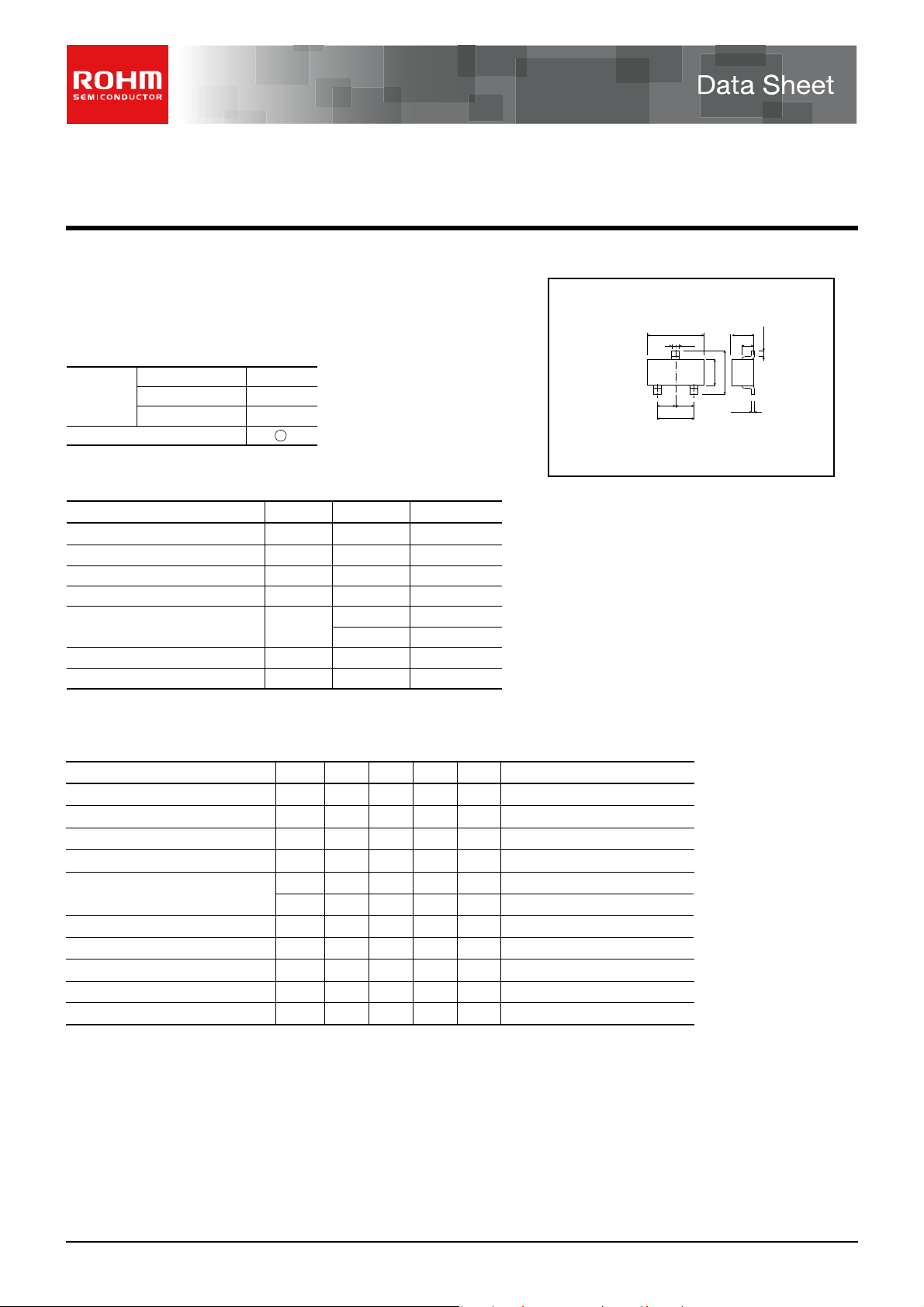
Features Dimensions (Unit : mm)
1) Ideal for switching and AF amplifier applications.
2) High current gain.
Packaging specifications
Type
BC857B
Package
Code
Basic ordering unit (pieces)
Taping
T116
3000
Absolute maximum ratings (Ta=25C)
Parameter
Collector-base voltage
Collector-emitter voltage
Emitter-base voltage
Collector current
Collector power dissipation
Junction temperature
Storage temperature
Mounted on a 7×5×0.6 mm CERAMIC SUBSTRATE
∗
Symbol Limits Unit
CBO
V
V
CEO
V
EBO
C
I
P
C
Tj
Tstg
−65 to 150
Electrical characteristics (Ta=25C)
CEO
CBO
EBO
CBO
BE(on)
h
FE
f
T
CBO
Min.
−45
−50
−5
−
−
−
−0.6
210 − 480
−
−−4.5
−
Parameter Symbol
Collector-emitter breakdown voltage
Collector-base breakdown voltage
Emitter-base breakdown voltage
Collector-base cutoff current
Collector-emitter saturation voltage
Base-emitter voltage
DC current transfer ratio
Transition frequency
Collector outpu capacitance
Collector-base cutoff current
BV
BV
BV
V
CE(sat1)
V
CE(sat2)
V
Cob
I
I
−50 V
−45
−5
−0.1
0.20
0.35
150
W
W
°C
V
V
A
∗
°C
Typ. Max. Unit Conditions
−
−
−
−
−
−
−
250
−
−
−
−
−0.015
−0.3
−0.65
−0.75
−
−4
MHz
C
VI
V
C
I
V
E
I
μA
V
I
V
C/IB
I
C/IB
V
V
−
V
V
V
V
μA
BC857B
(1)Emitter
(2)Base
(3)Collector
Abbreviated symbol : G3F
= −1mA
= −50μA
= −50μA
CB
= −30V
= −10mA/ −0.5mA
= −100mA/ −5mAV
CE
= −5V, IC= −10mA
CE
= 5V, IC= −2mA
CE
= −5V, IE= 20mA, f=100MHz
CB
= −10V, f=1MHzpF
CB
= −30V
0.95
2.9
0.4
(3)
(2)
(1)
0.95
1.9
0.95
0.45
0.2Min.
2.4
1.3
0.15
Each lead has same dimensions
www.rohm.com
1/2
c
○
2011 ROHM Co., Ltd. All rights reserved.
2011.11 - Rev.B
VCE=-5V
Ta=125ºC
75ºC
25ºC
-55ºC
IB=-50uA
IB=0A
IB=-100uA
IB=-150uA
IB=-200uA
IB=-250uA
IB=-500uA
450uA
400uA
350uA
-300uA
IC/IB=20/1
Ta=125ºC
75ºC
25ºC
-55ºC
VCE=-5V
Ta=125ºC
75ºC
25ºC
-55ºC
Ta=25 ºC
IC/IB=50/1
20/1
10/1
Ta=25 ºC
VCE=-5V
3V
-1V
IB=-20uA
IB=0A
IB=-25uA
IB=-30uA
IB=-35uA
IB=-50uA
IB=-45uA
IB=-40uA
IB=-15uA
IB=-10uA
IB=-5uA
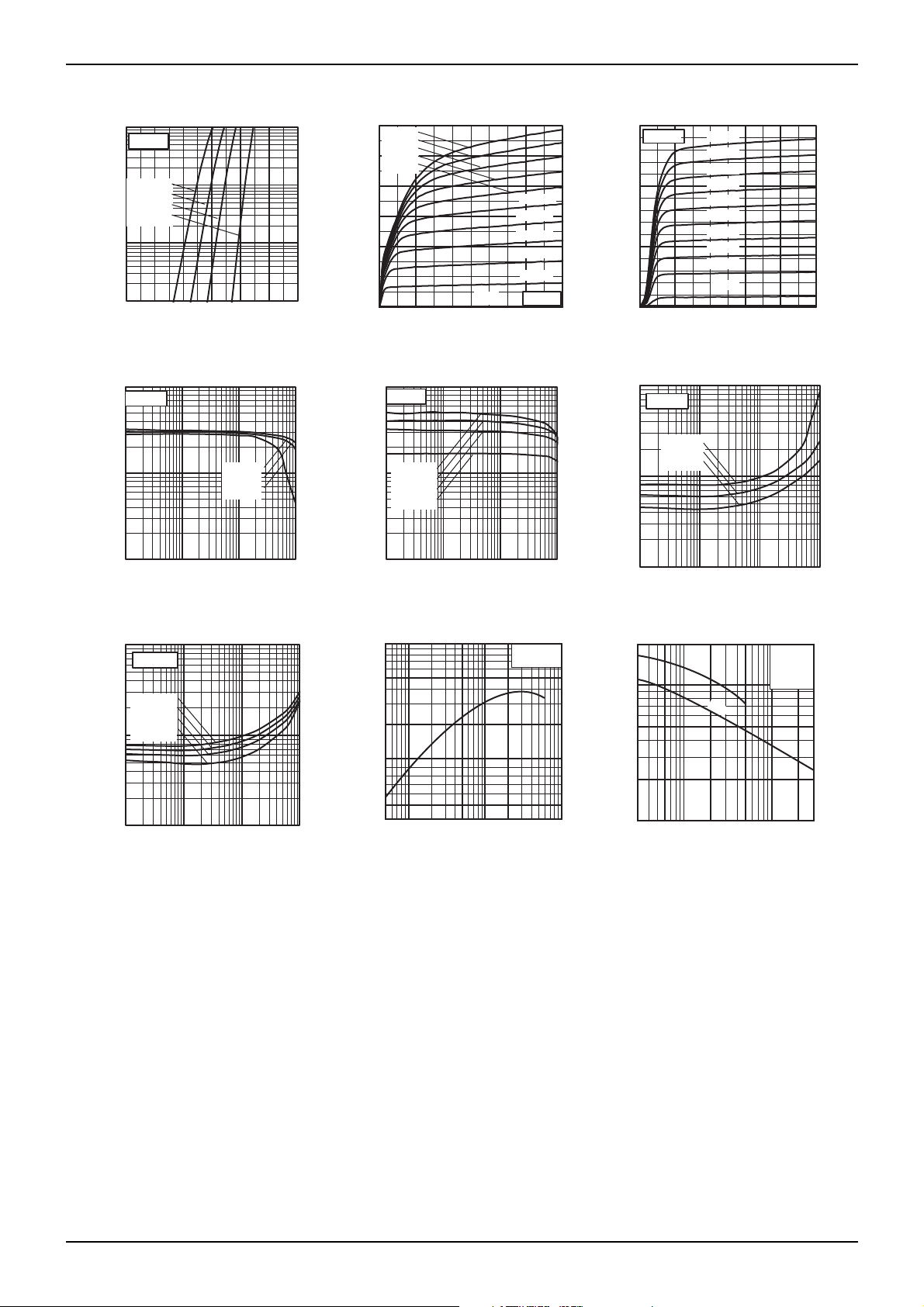
Electrical characteristics curves
-100
)Am(
C
I : TNERRUC ROTCELLOC
-10
-120
)
Am(
-100
C
I : TNERRUC ROTCELLOC
-80
-60
Data Sheet BC857B
-15
)Am(
C
I : TNERRUC ROTCELLOC
-10
Ta=25 ºC
-
-
-
-1
-0.1
0 -0.2 -0.4 -0.6 -0.8 -1 -1.2
BASE TO EMITTER VOLTAGE : VBE (V)
Fig 1. Grounded Emitter Propagation
Characteristics
1000
EF
h : NIAG TNERRUC CD
100
10
-0.1 -1 -10 -100
COLLECTOR CURRENT : IC (mA)
Fig 4. DC Current Gain vs.
Collector Current (I)
-1
: EGATLOV NOITAR
)V(
)tas(EC
-0.1
UTA
V
S
ROTCELLOC
-40
-5
-20
0
0-2-4-6-8-10
COLLECTOR TO EMITTER VOLTAGE : VCE (V)
Fig 2. Grounded Emitter Output
Characteristics (I)
1000
EF
h : NIAG TNERRUC CD
-
100
Ta=25 ºC
0
0 -0.4 -0.8 -1.2 -1.6 -2
COLLECTOR TO EMITTER VOLTAGE : VCE (V)
Fig 3. Grounded Emitter Output
Characteristics (II)
-1
: EGATLOV NOITARUTAS ROTCELLOC
)V(
)tas(EC
-0.1
V
10
-0.1 -1 -10 -100
COLLECTOR CURRENT : IC (mA)
Fig 5. DC Current Gain vs.
Collector Current (II)
1000
500
MHz)
(
T
200
100
Ta=25°C
V
CE
= −12V
-0.01
-0.1 -1 -10 -100
COLLECTOR CURRENT : IC (mA)
Fig 6. Collector Saturation Voltage
vs. Collector Current (I)
20
pF)
pF)
10
5
2
Cib
Cob
Ta=25°C
f=1MHz
I
E
=0A
I
C
=0A
50
-0.01
-0.1 -1 -10 -100
COLLECTOR CURRENT : IC (mA)
Fig 7. Collector Saturation Voltage
vs. Collector Current (II)
www.rohm.com
2/2
c
○
2011 ROHM Co., Ltd. All rights reserved.
TRANSITION FREQUENCY : f
12 510
50 1000.5 20
EMITTER CURRENT : I
Fig.8 Gain bandwidth product vs.
emitter current
E
(
mA)
−0.5 −20
−1 −2 −5 −10
COLLECTOR TO BASE VOLTAGE : VCB (V)
COLLECTOR OUTPUT CAPACITANCE : Cob (
EMITTER INPUT CAPACITANCE : Cib (
EMITTER TO BASE VOLTAGE : V
Fig.9
Collector output capacitance vs.
collector-base voltage
Emitter inputcapacitance vs.
emitter-base voltage
2011.11 - Rev.B
EB
(V)

Notes
Notice
www.rohm.com
© 2011 ROHM Co., Ltd. All rights reserved.
Thank you for your accessing to ROHM product informations.
More detail product informations and catalogs are available, please contact us.
ROHM Customer Support System
http://www.rohm.com/contact/
R1120A
 Loading...