


Communication ICs
Pseudo inductance for telephones
BA8201 / BA8201F
The BA8201 and BA8201F are ICs with a choke coil action, capable of extracting the DC current from a telephone line
while maintaining a high inductance on the telephone line side. This eliminates the need for a choke coil, and facilitates
use of the telephone set line in a variety of applications.
Applications
Household telephones
Features
1) Corresponds to choke coil of several henries.
2) Extracts DC current while maintaining high inductance on telephone line side.
3) Capable of extracting large output current.
4) Wide dynamic range.
5) Two output voltage modes available for selection.
Line voltage seek mode
Constant voltage mode
6) DIP 8 and SOP 8 pin packages available.
Absolute maximum ratings (Ta = 25C)
Recommended operating conditions (Ta = 25C)
300

Communication ICs BA8201 / BA8201F
Block diagram
301
Communication ICs BA8201 / BA8201F
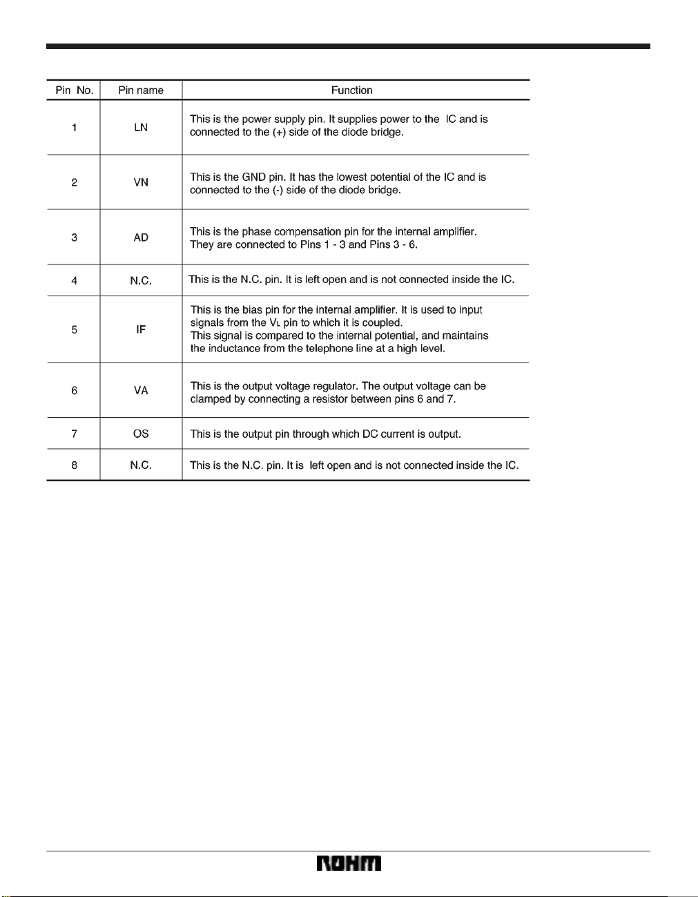
Pin descriptions
302

Communication ICs BA8201 / BA8201F
Electrical characteristics (unless otherwise noted, Ta = 25C, VLN = 4V, υLN = 100mVrms, Io = 5mA, f = 1kHz)
Measurement circuits
303

Communication ICs BA8201 / BA8201F
304

Communication ICs BA8201 / BA8201F
Application example
Attached components
C1:
This is a capacitor for phase compensation, and is normally connected at 68pF.
C2:
This is a coupling capacitor. The inductance from the
telephone line changes based on this value. Normally , a
value of 2.2µF to 10µF is appropriate.
C3:
This is a capacitor for phase compensation, and is normally connected at 47pF.
C4:
This is the capacitor for balancing the output. It suppresses rippling in the output and also carries out decoupling for the bias voltage supply of the IF pin. It should
be adjusted based on the output current, load, and other
factors.
R1:
Bias is applied from this pin to the IF pin. The inductance
from the telephone line changes based on this value.
Normally, a value of 100kΩ is appropriate.
R2:
This can be connected between Pins 6 and 7 to clamp the
output voltage. The output voltage is expressed using the
equation below.
Vo (V) = 2 22 (µA) R2 (Ω) (reference value)
∗22µA is the reference internal current source for
the IC.
305

Communication ICs BA8201 / BA8201F
Electrical characteristic curves
306

Communication ICs BA8201 / BA8201F
External dimensions (Units: mm)
307
 Loading...