

1
Video ICs
Stereo zoom microphone amplifier
for camcorders
BA7780KV
The BA7780KV is a microphone amplifier developed for use in camcorders. The IC features an electronic volume circuit for presetting the curve required for the stereo zoom function, a microphone element power supply regulator, a
wind-noise rejection filter, a current limiting circuit for external accessory power supplies, and an input for external
microphone input. The IC operates off a 3.3V power supply.
•
Applications
Camcorders
•
Features
1) Operates off a 3.0V to 5.25V power supply.
2) Zoom microphone processing function on one chip.
3) Built-in electronic volume for external setting of sensitivity and control voltage.
4) Adjustable microphone element sensitivity.
5) Matrix amplifier for stereo emphasis.
6) Automatic switching circuit for external inputs, and
built-in external monaural decision circuit.
•
Absolute maximum ratings (Ta = 25°C)
•
Recommended operating conditions (Ta = 25°C)
Parameter
Symbol Limits Unit
V
CC
7.0 V
Pd 750
∗
mW
Topr
°C
Tstg °C
– 10 ~ + 70
– 55 ~ + 125
Power supply voltage
Power dissipation
Operating temperature
Storage temperature
∗
Reduced by 7.5mW for each increase in Ta of 1°C over 25°C.
Parameter Symbol Min. Typ. Max. Unit
V
CCS 3.0 — 5.25 V
Power supply voltage
2
Video ICs BA7780KV
•
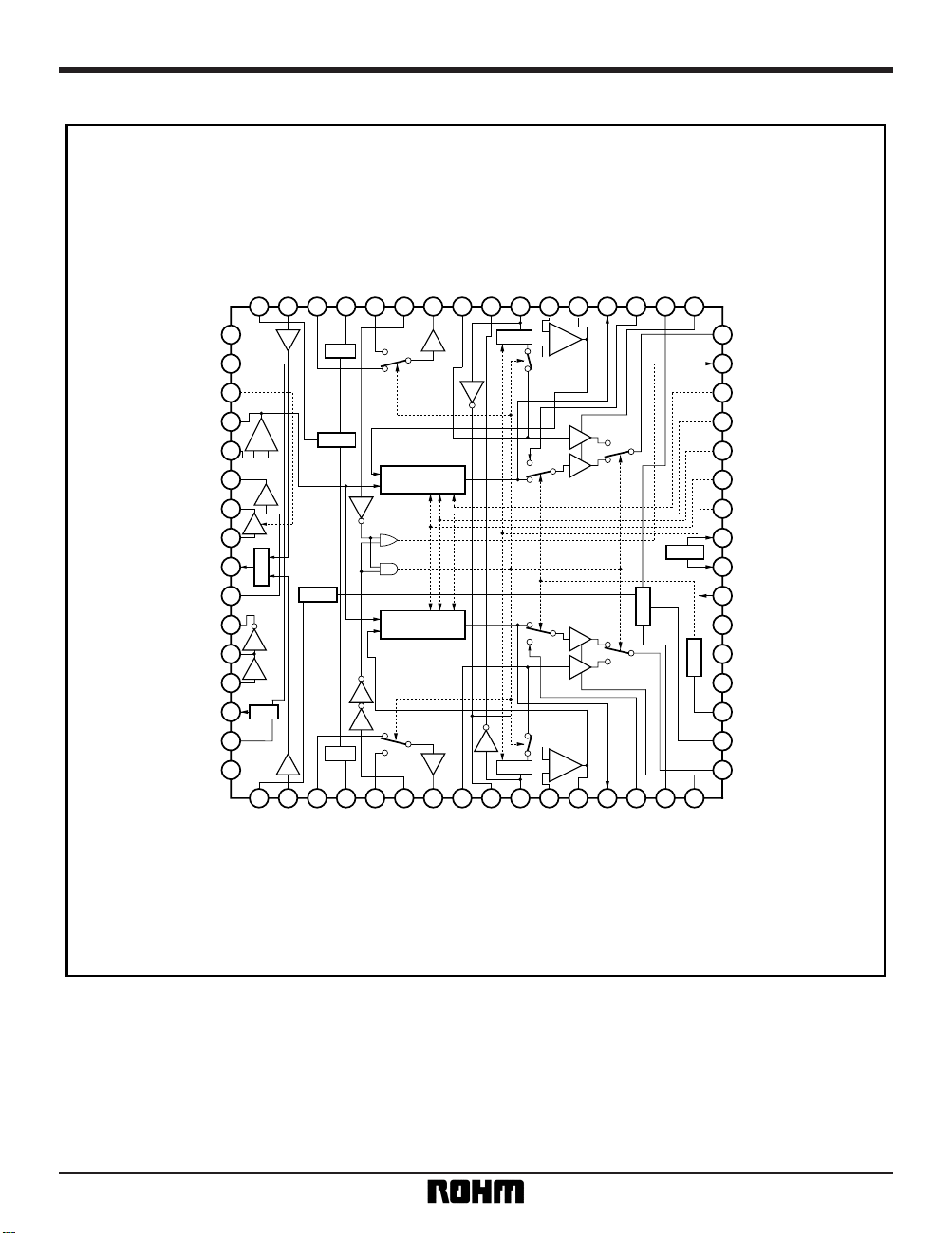
Block diagram
01 02 03 04 05 06 07 08 09 10 11 12 13 14 15 16
32
31
30
29
28
27
26
25
24
23
22
21
20
19
18
17
48 47 46 45 44 43 42 41 40 39 38 37 36 35 34 33
49
50
51
52
53
54
55
56
57
58
59
60
61
62
63
64
MIX
REC
EXT
INT
13dB
GC
–
+
15dB
5dB
EXT
INT
BALANCE
RFLT
EXT
INT
13dB
RFLT
MIX
13dB
BALANCE
INT: 0N
GC
15dB
5dB
EXT
INT
BIAS
HPFC
CImt
13dB
OUT L
MIC MONO
Z B
Z A
Z SENSE
Z POINT
GAIN CONT
EX V
CC OUT
EX V
CC
VCC
Z AC
Z BC
IN MONI
HPF CONT
BIAS SUB
OUT R
BG
SUB IN L
INT IN L
VREG L
EXT IN L
MODE 43
PRE OUT L
OUT AMP IN L
INV OUT L
GC OUT L
MTX IN L
MTX OUT L
BL OUT L
HPF IN L
BIAS L
EXTC L
RIPL
SUB IN R
INT IN R
VREG R
EXT IN R
MODE 6
PRE OUT R
OUT AMP IN R
INV OUT R
GC OUT R
MTX IN R
MTX OUT R
BL OUT R
HPF IN R
BIAS R
EXTC R
GND L
MIX1 IN L
GZ CONT
SUB INV2 OUT
SUB INV2 IN
SUB BUF2 OUT
SUB VCA OUT
SUB VCA IN
MIX2 OUT
SUB BUF2 IN
SUB INV1 OUT
SUB BUF1 OUT
SUB BUF1 IN
MIX1 OUT
MIX1 IN R
GND R
INT: ON
REG
–
+
+–
3
Video ICs BA7780KV
•
Pin descriptions
1 RIPL 1.65 50kΩ
2 1.65 100kΩ
3 1.65 75kΩ
4 2.5 C
5 1.65 75kΩ
6 — 25kΩ
7 1.65 EF (P - P)
8 1.65 100kΩ
9 1.65 EF (P - P)
10 1.65 EF (P - P)
11 1.65 B
12 1.65 EF (P - P)
13 1.65 EF (P - P)
14 1.65 100kΩ
15 1.65 EF (P - P)
16 2.3 C
17 1.65 C (P - P)
18 1.65 EF (P - P)
19 — 10kΩ
20 —C
21 —B
22 —B
23 VCC 3.3 —
24 4.75 —
25 4.5 C
26 — 50kΩ
27 —B
28 —B
29 —B
30 —B
31 —C
32 1.65 EF (P - P)
33 2.3 C
34 1.65 EF (P - P)
35 1.65 100kΩ
36 1.65 EF (P - P)
37 1.65 EF (P - P)
38 1.65 B
39 1.65 EF (P - P)
40 1.65 EF (P - P)
41 1.65 100kΩ
42 1.65 EF (P - P)
SUB IN R
INT IN R
VREG R
EXT IN R
MODE 6
OUT AMP IN R
PRE OUT R
INV OUT R
GC OUT R
MTX IN R
MTX OUT R
BL OUT R
HPF IN R
BIAS R
EXTC R
OUT R
BIAS SUB
HPF CONT
IN MONI
Z BC
Z AC
EX V
CC
EX VCC OUT
GAIN CONT
Z POINT
Z SENSE
Z A
Z B
MIC MONO
OUT L
EXTC L
BIAS L
HPF IN L
BL OUT L
MTX OUT L
MTX IN L
GC OUT L
INV OUT L
OUT AMP IN L
PRE OUT L
Pin No.
For bias ripple filter capacitor
Sub microphone input
Internal microphone input
Regulator output
External microphone input
Mode control 6 input
Preamplifier output
Out amplifier input
Inverter output
Gain control amplifier output
Matrix amplifier input
Matrix amplifier output
Zoom balance circuit output
HPF input
Bias output
For connection of out amplifier output inhibit capacitor
Signal output
Sub bias output
HFP control input
Input switch decision signal output
For connection of noise cutting capacitor for zoom control signal
For connection of noise cutting capacitor for zoom control signal
V
CC
Current limiter VCC
Current limiter output
Gain control amplifier switch input
Cross-point variation input for zoom balance circuit
Sensitivity variation input for zoom balance circuit
Zoom control input
Zoom control input
External microphone monaural decision signal output
Signal output
For connection of out amplifier output inhibit capacitor
Bias output
HPF input
Zoom balance circuit output
Matrix amplifier output
Matrix amplifier input
Gain control amplifier output
Inverter output
Out amplifier input
Preamplifier output
Pin voltage (V)
FormatFunction
Pin name

4
Video ICs BA7780KV
Pin No.
43 MODE 43 — 25kΩ
44 EXT IN L 1.65 75kΩ
45 VREG L 2.5 C
46 INT IN L 1.65 75kΩ
47 SUB IN L 1.65 100kΩ
48 BG 1.25 10kΩ
49 GND L ——
50 MIX 1 IN L 1.65 100kΩ
51 GZ CONT — 50kΩ
52 SUB INV2 OUT 1.65 EF (P - P)
53 SUB INV2 IN 1.65 B
54 SUB BUF2 OUT 1.65 EF (P - P)
55 SUB VCA OUT 1.65 EF (P - P)
56 SUB VCA IN 1.65 100kΩ
57 MIX2 OUT 1.65 EF (P - P)
58 SUB BUF2 IN 1.65 100kΩ
59 SUB INV1 OUT 1.65 EF (P - P)
60 SUB BUF1 OUT 1.65 EF (P - P)
61 SUB BUF1 IN 1.65 100kΩ
62 MIX1 OUT 1.65 EF (P - P)
63 MIX1 IN R 1.65 100kΩ
64 GND R ——
Pin voltage (V)
FormatFunction
Pin name
Mode control 43 input
External microphone input
Regulator output
Internal microphone input
Sub microphone input
For regulator ripple filter capacitor
Left channel GND
Mixer amplifier input
Sub VCA control input
Sub inverter 2 output
Sub inverter 2 input
Sub buffer 2 output
Sub VCA output
Sub VCA input
Mixer 2 output
Sub buffer 2 input
Sub inverter 1 output
Sub buffer 1 output
Sub buffer 1 input
Mixer 1 output
Mixer 1 input
Right channel GND
∗
EF: emitter follower, P-P: push pull, B: base, and C: collector. All numerical values are standardized values.

5
Video ICs BA7780KV
Parameter
Symbol Min. Typ. Max. Unit
Conditions
I
qE — 8.5 12.0 mA
GV
E 27.0 28.0 29.0 dB
GV
IH 21.5 24.5 27.5 dB
GV
IM 18.5 21.5 24.5 dB
GV
IL 16.5 18.5 21.5 dB
THD
W — 0.05 0.5 %
THD
E — 0.1 0.25 %
THD
Z — 0.15 0.5 %
V
OM 0.75 0.95 — Vrms
VONE —3060µVrms
VONW —3060µVrms
VONZ — 60 120µVrms
CTIE — – 76 – 70 dB
CT
CH — – 76 – 70 dB
GV
GLR – 1.5 0.0 1.5 dB
10 39
GVILR – 1.5 0.0 1.5 dB
940
VREG 2.3 2.5 2.75 V
V
EXT 4.3 4.5 — V
I
LTD — — 30 mA
V
HSWH 1.6 — V
V
HSWL 0—0.7V
V
HGH 2.8 — V
V
HGM 1.3 — 2.0 V
V
HGL 0—0.5V
V
HHPFH 2.0 — V
V
HHPFL 0—0.5V
GV
M1-1 – 7.0 – 6.0 – 5.0 dB
GV
M1-2 – 1.0 0 1.0 dB
GV
M2-1 6.0 7.0 8.0 dB
GV
M2-2 – 1.0 0 1.0 dB
EXT MIC IN, VO = 300mVrms
Note 1
Note 2
V
CC
V
CC
V
CC
GAIN CTL H
INT MIC IN, ZOOM, V
O
= 300mVrms
INT MIC IN, WIDE, Vo = 300mVrms
INT MIC IN, GAIN CTL L
INT MIC IN, GAIN CTL M
INT MIC IN, GAIN CTL H
EXT MIC IN
INT / EXT MIC IN, No input
Pins 29 and 30 = 0V, GAIN CTL H
INT MIC IN, HML,
INT MIC IN, HML,
HPF OFF, 19pin DC
HPF ON, 19pin DC
63→62 / 50→62 pin
INT L / M / H, 2→57, 47→57pin
INT / EXT MIC IN, THD = 1%
∗
2
EXT MIC IN, R
g = 1k
Ω
∗
1
INT MIC IN, R
g = 1k
Ω
∗
1
INT MIC IN, R
g = 1k
Ω
∗
1
Current dissipation
Voltage gain 1
Voltage gain 2
Voltage gain 3
Voltage gain 4
Distortion 1
Distortion 2
Distortion 3
Maximum output
Output noise voltage 1 (EXT)
Output noise voltage 2 (INT, WIDE)
Output noise voltage 3 (INT, ZOOM)
Input switch crosstalk (INT to EXT)
Interchannel crosstalk
GC OUT L / R gain differential
Inverter OUT L / R gain differential
Internal microphone power supply output voltage
External power supply output voltage
External power supply limit current
Input switching CTL holding voltage
Gain switching CTL holding voltage
HPF, CTL holding voltage
MIX 1 gain
MIX 2 gain
Pins 4 and 45 output current for 30kΩ load
Pin 25 DC for pin 25 output current of 25mA
Pin 25 output current when grounded
“H” level, pin 6 / 43 DC
“L” level, pin 6 / 43 DC
“H” level, pin 26 DC
“M” level, pin 26 DC
“L” level, pin 26 DC
Gain differential for pins 63 to 62 and 50 to 62
Gain differential for pins 2 to 57 and 47 to 57
•
Electrical characteristics
Measurement conditions
Unless otherwise noted, the following conditions apply:
Ta = 25°C, V
CC3.3V, external supply voltage (pin 24) =
4.75V, pin 19 = “H” or open, pin 26 = 1 / 2V
CC, pin 51 =
0.58 × pin 4, pin 27 = 0.733 × pin 4, pin 28 = 0.80 × pin 4,
pin 29 = 2.2V, pin 30 = 2.2V
Input signal level Int = – 31.5dBV
Ext = – 38.5dBV
Sub = – 33.5dBV (1kHz)
Monitoring pins: 17 and 32
∗ 1 JIS–A filter used
∗ 2 400Hz to 30kHz filter used

6
Video ICs BA7780KV
GV
Z1-1
– 23.0 – 20.0 – 17.0 dB 29, 30 pin 0.0V (DC)
GV
Z1-2
– 11.7 – 7.7 – 4.7 dB 29, 30 pin 0.8V (DC)
GV
Z1-3
– 2.0 1.0 4.0 dB 29, 30 pin 2.2V (DC)
GV
Z2-1
– 23.0 – 20.0 – 17.0 dB 29, 30 pin 2.2V (DC)
GV
Z2-2
– 11.7 – 7.7 – 4.7 dB 29, 30 pin 1.4V (DC)
GV
Z2-3
– 2.0 1.0 4.0 dB 29, 30 pin 0.0V (DC)
Parameter
Symbol Unit
Conditions
Min. Typ. Max.
GV
Z3–1
– 2.5 0.5 3.5 dB 27 pin 0.64
× 4pin (DC)
GV
Z3–2
– 7.5 – 4.5 – 1.5 dB 27 pin 0.733
× 4pin (DC)
GV
Z3–3
– 20.6 – 17.0 – 12.0 dB 27 pin 0.82
× 4pin (DC)
GV
Z4–1
– 5.5 – 2.5 0.5 dB 28 pin 0.59
× 4pin (DC)
GV
Z4–2
– 9.5 – 6.5 – 3.5 dB 28 pin 0.69
× 4pin (DC)
GV
Z4–3
– 17.5 – 14.5 – 11.5 dB 28 pin 0.8
× 4pin (DC)
GV
VCA1
– 5.0 – 3.0 – 1.0 dB 51 pin 0.74
× 4pin (DC)
GV
VCA2
– 2.0 0.0 2.0 dB 51 pin 0.58
× 4pin (DC)
GV
VCA3
1.0 3.0 5.0 dB 51 pin 0.48
× 4pin (DC)
12
→13 or 37→36 pin
52→13 or 52→36 pin
28 pin 0.8 × 4pin, 29 30 pin 1.1V,
12→13 or 37→36 pin
27 pin 0.733 × 4pin, 29 30 pin 0.4V,
12→13 or 37→36 pin
Sub VCA gain
Variable slope
Variable position
Gain 2
Gain 1
Rch / Lch
Rch / Lch
Rch / Lch
Rch / Lch
56pin 55pin
ZOOM - BALANCE
ZOOM - BALANCE
ZOOM - BALANCE
ZOOM - BALANCE
Note 1: Input switch crosstalk measurement method:
(pin 19 = “H” or open, pin 26 = GND, pin 27 = 0.733 × pin 4, pin 28 = 0.80 × pin 4, pin 29 = 2.2V, pin 30 = 2.2V)
Input 1kHz signals on the INT input pins (3 and 46) in INT input mode that give a distortion of 1% at the signal output pins (17 and 32), then
connect the EXT input pins (5 and 44) to GND via R
g = 1kΩ Switch to EXT input mode, and measure the relative output level of the output pins
(17 and 32).
Note 2: Interchannel crosstalk measurement method:
The mode pin conditions are the same as for input switch crosstalk.
Connect the input pin of the channel to be measured to GND via R
g = 1kΩ. Input a 1kHz signal on the other channel's input that gives a distortion
of 1% on the signal output pins (17 and 32), and measure the relative output level between the signal output pins (17 and 32).

7
Video ICs BA7780KV
01 02 03 04 05 06 07 08 09 10 11 12 13 14 15 16
323130292827262524232221201918
17
48 47 46 45 44 43 42 41 40 39 38 37 36 35 34 33
495051525354555657585960616263
64
MIX
EXT
INT
13dB
GC
15dB
5dB
EXT
INT
BALANCE
EXT
INT
13dB
MIX
13dB
BALANCE
GC
15dB
5dB
EXT
INT
BIAS
CImt
13dB
MIC MONO
Z B
Z A
V
CC
Z AC
Z BC
IN MONI
SUB BIAS
10k
10k
0.1
0.1
0.1
0.1
30k
0.1
0.1
2200p
0.022
1
2
10
+
0.1
0.1
10k
10k
10k
32k
1
2
3
SW1
0.1
0.1
0.1
0.1
470p
SW3
10k
10k
0.1
0.1
0.1
0.1
30k
0.1
0.1
2200p
0.022
1
2
10
+
470p
MODE6
SW2
MODE43
GND
Z SENSE
Z POINT
GAIN CONT
EX V
CC
OUT
EX V
CC
IN
INT: ON
INT: ON
SUB MIC IN
INT MIC IN
EXT MIC IN
EXT MIC IN
INT MIC IN
SUB MIC IN
RFLT
RFLT
GZ
CONT
REG
REG
Lch OUT
Rch OUT
HPF ON / OFF
Units:
HPFC
R [Ω]
C [µF]
Fig. 1
–+
–+
+
–
•
Measurement circuit

8
Video ICs BA7780KV
SW1 SW2 SW3 MODE6 MODE43 GAIN CTL
1
—
—
—
—
—
—
—
—
—
—
—
—
—
—
—
—
—
—
—
—
—
—
—
—
—
—
—
—
—
—
—
—
—
—
—
—
—
—
—
—
—
—
—
—
—
—
—
—
—
—
—
—
—
—
—
—
—
—
—
—
—
—
—
—
—
—
—
—
—
—
—
—
—
—
—
—
—
—
—
—
—
—
1 1 H, L H, L M
LL—M Ext
—
—
—
—
—
—
—
H H Int
M Int
L Int
2HLM
—
—
—
—
—
—
—
—
—
—
—
Int
2 L L Ext
1 H L M Sub
1 H, L L L Int, Ext, Sub
2LL
2HLH
3HLH
2 L L L Int
INT 2 H L M Int
EXT 2 L L Ext
1 H L H, M, L Int
1 H L H, M, L Int
2 H Vth Int, Ext
2 Vth L Int, Ext
2 H L Vth Int
2 H L Vth Int
2 H L Vth Int
2 2.1 2.1 H L
H L M Int
H L Sub
2 H L M Int
1 H L M Sub
2 H L M Int
2 H L M Int
H L Sub
Int, Vth of pin 19
Signal input pin
Parameter
Current dissipation
Voltage gain 1
Voltage gain 2
Voltage gain 3
Voltage gain 4
Distortion 1
Distortion 2
Distortion 3
Maximum output
Output noise voltage 1 (EXT)
Output noise voltage 2 (WIDE)
Output noise voltage 3 (ZOOM)
Input switch crosstalk (INT to EXT)
Interchannel crosstalk
GC out L / R gain differential
Inverter OUT L / R gain differential
Internal microphone power supply voltage
External power supply output voltage
External power supply limit current
Input switching CTL holding voltage
Gain switching CTL holding voltage
HPF, CTL holding voltage
MIX 1 gain
MIX 2 gain
ZOOM - BALANCE Gain 1
ZOOM - BALANCE Gain 2
ZOOM - BALANCE Variable position
ZOOM - BALANCE Variable inclination
Sub VCA gain
∗
Gain CTL pin 26.
H, M, and L are V
CC, 1/2VCC, and GND respectively.
Measure the voltage range that maintains the mode for Vth.
•
Measurement circuit switching table (blank cells: no spesification)

9
Video ICs BA7780KV
01 02 03 04 05 06 07 08
09 10
11 12 13 14 15 16
32
313029
28
272625
242322
2120191817
48 47 46 45 44 43 42 41 40 39 38 37 36 35 34 33
49
505152
53
545556
575859
6061626364
MIX
EXT
INT
13dB
GC
15dB
5dB
EXT
INT
BALANCE
RFLT
EXT
INT
13dB
RFLT
MIX
13dB
BALANCE
INT: 0N
GC
15dB
5dB
EXT
INT
BIAS
CImt
INT: 0N
13dB
MIC MONO
Z B
Z A
V
CC
Z AC
Z BC
IN MONI
SUB BIAS
10k
0.1
0.1
0.1
0.1
0.1
0.022
10
+
0.1
0.1
10k
10k
10k
0.1
0.1
0.1
470p
0.1
0.1
0.1
0.1
10
+
0.022
2200
6800
2200
0.022
2200
6800
2200
33k
3300
12k
6800p
6800p
0.047
3300
10k
2200p
22k
0.022
0.022
8200
10k
0.1
0.022
470p
33k
3300
12k
6800p
6800p
0.047
3300
10k
2200p
22k
0.022
0.022
8200
5600p
10k
GND
10k
0.010
0.01
1k
1500
10k
2700p
10k
EXT MIC IN
INT MIC IN
SUB MIC IN
SUB MIC IN
INT MIC IN
EXT MIC IN
6800p
3900p
47k
Z SENSE
Z POINT
GAIN CONT
EX V
CC OUT
EX V
CC IN
GZ CONT
HPF ON / OFF
REG
Lch OUT
Rch OUT
HPFC
REG
Units: R [Ω]
C [µF]
Fig. 2
–+
–+
+
–
•
Application example

•
Operation notes
Points to note regarding zoom operation
When using a microprocessor to vary the voltages on pins 29 and
30 after presetting the electronic volume sensitivity and control voltage range, and with the pin 27 and 28 voltage fixed at a certain
level, it is possible to minimize drift in the zoom characteristics due
to tempreature fluctuations and differences between individual ICs
by setting the pin 27 and 28 voltages using resistive voltage divider
circuits connected to the pin 4 regulator voltage output.
10
Video ICs BA7780KV
•
Electrical characteristic curves
17, 32pin OUTPUT ATTENUATION LEVEL: GVZ1 (dB)
29, 30pin CONTROL VOLTAGE: VCTL (V)
– 20
0.1
– 15
– 10
– 5
0
0.6 1.1 1.6 2.1
28pin
=
1.64V
1.84V
1.94V
2.04V
28pin
=
1.64V
1.84V
1.94V
2.04V
Ta = 25°C
12→13, 37→36pin
52→13, 52→36pin
0 2.2
Fig. 4 Zoom control slope variation
characteristics
4
27
28
Fig. 3
17, 32pin OUTPUT ATTENUATION LEVEL: GVZ1 (dB)
29, 30pin CONTROL VOLTAGE: VCTL (V)
– 20
0.1
– 15
– 10
– 5
0
0.6 1.1 1.6 2.1
27pin
=
1.67V
1.87V
1.67V
Ta = 25°C
12→13, 37→36pin
52→13, 52→36pin
2.07V
1.87V
27pin
=
1.67V
0 2.2
Fig. 5 Zoom control position variation
characteristics
•
External dimensions (Units: mm)
VQFP64
48
33
32
17
16
1
49
64
10.0 ± 0.2
12.0 ± 0.3
10.0 ± 0.2
12.0 ± 0.3
0.2 ± 0.1
0.5
0.125 ± 0.1
0.5
0.10
1.4 ± 0.1
0.10
 Loading...