

Page 1
Reversible Motor Drivers for Brush Motors
1.0A Reversible
Motor Drivers (Single Motor)
BA6956AN,BA6287F,BA6285FS,BA6285AFP-Y,BA6920FP-Y
●Description
The reversible motor driver for output 1.0A for 1 motor can set the output modes to four modes, normal, reverse, stop
(idling), and braking in accordance with logic input (2 inputs).
●Features
1) Built-in surge absorption diode
2) By built-in power save circuit, current consumption when a motor stops (idles) can be suppressed
3) Output voltage can be optionally set by reference voltage setting pin
4) Built-in thermal shutdown circuit (TSD)
●Applications
Audio-visual equipment; PC peripherals; Car audios; Car navigation systems; OA equipments
●Absolute maximum ratings (Ta=25℃, All voltages are with respect to ground)
Parameter Symbol
Supply voltage VCC 18 18 18 30 36 V
Supply voltage VM 18 18 18 30 36 V
Output current I
OMAX
BA6956AN BA6287F BA6285FS BA6285AFP-Y BA6920FP-Y
1*1 1*1 1*1 1*1 1*1 A
Ratings
No.11008EBT02
Unit
Operating temperature T
Storage temperature T
Power dissipation Pd 1.19*2 0.689*3 0.813*4 1.45*5 1.45*5 W
Junction temperature T
*1 Do not, exceed Pd or ASO.
*2 SIP9 package. Derated at 9.5mW/℃ above 25℃.
*3 SOP8 package. Mounted on a 70mm x 70mm x 1.6mm FR4 glass-epoxy board with less than 3% copper foil. Derated at 5.52mW/℃ above 25℃.
*4 SSOP-A16 package. Mounted on a 70mm x 70mm x 1.6mm FR4 glass-epoxy board with less than 3% copper foil. Derated at 6.5mW/℃ above 25℃.
*5 HSOP25 package. Mounted on a 70mm x 70mm x 1.6mm FR4 glass-epoxy board with less than 3% copper foil. Derated at 11.6mW/℃ above 25℃.
●Operating conditions (Ta=25℃)
Parameter Symbol
Supply voltage VCC 6.5 ~ 15 4.5 ~ 15 4.5 ~ 15 4.5 ~ 24 6.5 ~ 34 V
Supply voltage VM 6.5 ~ 15 4.5 ~ 15 4.5 ~ 15 4.5 ~ 24 6.5 ~ 34 V
VREF voltage VREF < VCC, VM < VCC, VM < VCC, VM < VCC, VM < VCC, VM V
-20 ~ 75 -20 ~ 75 -20 ~ 75 -40 ~ 85 -30 ~ 85 ℃
OPR
-55 ~ 150 -55 ~ 150 -55 ~ 150 -55 ~ 150 -55 ~ 150 ℃
STG
150 150 150 150 150 ℃
jmax
Ratings
BA6956AN BA6287F BA6285FS BA6285AFP-Y BA6920FP-Y
Unit
www.rohm.com
© 2011 ROHM Co., Ltd. All rights reserved.
1/17
2011.05 - Rev.B
Page 2
BA6956AN,BA6287F,BA6285FS,BA6285AFP-Y,BA6920FP-Y
●Electrical characteristics (BA6956AN, unless otherwise specified, Ta=25℃ and VCC=9V, VM=9V)
Parameter Symbol
Min. Typ. Max.
Limits
Unit Conditions
Technical Note
Supply current 1 I
Supply current 2 I
Supply current 3 I
- 29 44 mA FWD/REV mode
CC1
- 56 80 mA Brake mode
CC2
- 0 15 µA Standby mode
CC3
Input threshold voltage H VIH 2.0 - VCC V
Input threshold voltage L VIL 0 - 0.8 V
Input bias current IIH 50 90 131 µA VIN=2V
Output saturation voltage VCE - 1.7 2.3 V IO=0.2A, vertically total
VREF bias current I
- 10 25 µA IO=0.2A, VREF=6V
REF
●Electrical characteristics (BA6287F, unless otherwise specified, Ta=25℃ and VCC=9V, VM=9V, VREF=9V)
Parameter Symbol
Supply current 1 I
Supply current 2 I
Min. Typ. Max.
12 24 36 mA FWD/REV mode
CC1
29 48 67 mA Brake mode
CC2
Limits
Unit Conditions
Standby current IST - 0 15 µA Standby mode
Input threshold voltage H VIH 2.0 - VCC V
Input threshold voltage L VIL 0 - 0.8 V
Input bias current IIH 45 90 135 µA VIN=2V
Output saturation voltage VCE - 1.0 1.5 V IO=0.2A, vertically total
VREF bias current I
6 12 18 mA IO=0.2A, FWD or REV mode
REF
●Electrical characteristics (BA6285FS, unless otherwise specified, Ta= 25℃ and VCC=9V, VM=9V, VREF=9V)
Parameter Symbol
Supply current 1 I
Supply current 2 I
Min. Typ. Max.
12 24 36 mA FWD/REV mode
CC1
29 48 67 mA Brake mode
CC2
Limits
Unit Conditions
Standby current IST - 0 15 µA Standby mode
Input threshold voltage H VIH 2.0 - VCC V
Input threshold voltage L VIL 0 - 0.8 V
Input bias current IIH 45 90 135 µA VIN=2V
Power save on voltage V
Power save off voltage V
2.0 - VCC V Standby mode
PSON
0 - 0.8 V Operation
PSOFF
Output saturation voltage VCE - 1.0 1.5 V IO=0.2A, vertically total
VREF bias current I
www.rohm.com
© 2011 ROHM Co., Ltd. All rights reserved.
6 12 18 mA IO=0.2A, FWD or REV mode
REF
2/17
2011.05 - Rev.B
Page 3

BA6956AN,BA6287F,BA6285FS,BA6285AFP-Y,BA6920FP-Y
Technical Note
●Electrical characteristics (BA6285AFP-Y, unless otherwise specified, Ta=25℃ and VCC=9V, VM=9V, VREF=9V)
Parameter Symbol
Min. Typ. Max.
Limits
Unit Conditions
Supply current 1 I
Supply current 2 I
10 20 30 mA FWD/REV mode
CC1
21 42 63 mA Brake mode
CC2
Standby current IST - 0 15 µA Standby mode
Input threshold voltage H VIH 2.0 - VCC V
Input threshold voltage L VIL 0 - 0.8 V
Input bias current IIH 40 80 120 µA VIN=2V
Power save on voltage V
Power save off voltage V
- - 0.8 V Operation
PSON
2.0 - VCC V Standby mode
PSOFF
Output saturation voltage VCE - 1.0 1.5 V IO=0.2A, vertically total
VREF bias current I
9 15 21 mA IO=0.2A, FWD or REV mode
REF
●Electrical characteristics (BA6920FP-Y, unless otherwise specified, Ta=25℃ and VCC=12V, VM=12V)
Parameter Symbol
Supply current 1 I
Supply current 2 I
Min. Typ. Max.
5 8 12 mA FWD/REV mode
CC1
3 5 8 mA Brake mode
CC2
Limits
Unit Conditions
Standby current IST - 0 15 µA Standby mode
Input threshold voltage H VIH 3.0 - VCC V
Input threshold voltage L VIL 0 - 0.8 V
Input bias current IIH 100 200 300 µA VIN=3V
Power save on voltage V
Power save off voltage V
2.0 - VCC V Standby mode
PSON
- - 0.8 V Operation
PSOFF
Output saturation voltage VCE - 2.2 3.3 V IO=0.2A, vertically total
VREF bias current I
- 12 35 µA IO=0.1A, VREF=6V
REF
www.rohm.com
© 2011 ROHM Co., Ltd. All rights reserved.
3/17
2011.05 - Rev.B
Page 4
BA6956AN,BA6287F,BA6285FS,BA6285AFP-Y,BA6920FP-Y
Technical Note
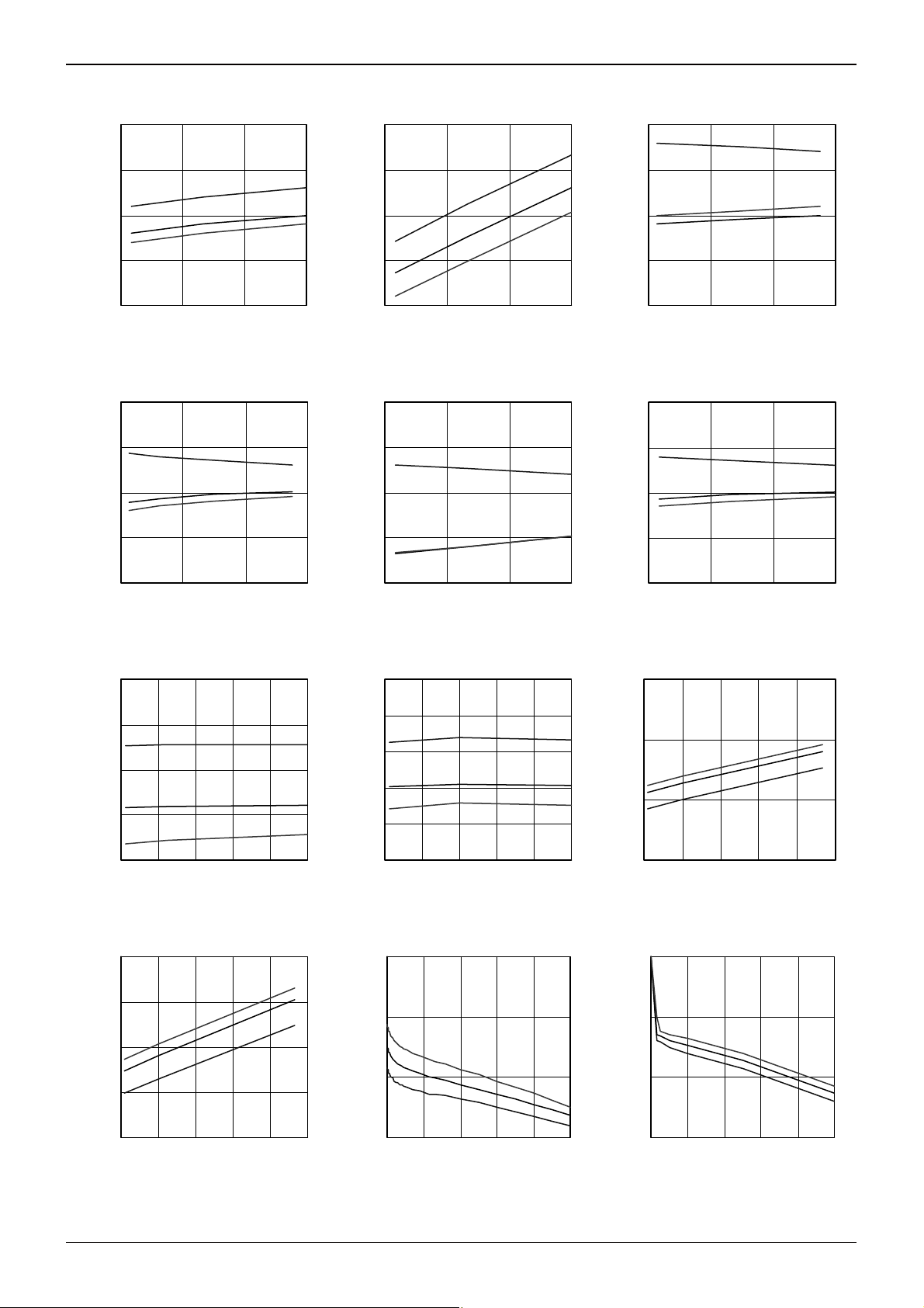
●Electrical characteristic curves (Reference data)
40
80
30
35
70
25
30
60
20
25
Supply Current: Icc1 [mA] _
20
6 9 12 15
Supply Voltage: Vcc [V]
Fig.1 Supply current 1 (forward) Fig.2 Supply current 2 (brake) Fig.3 Supply current 1 (forward)
(BA6956AN) (BA6956AN) (BA6287F)
60
-20°C
25°C
75°C
50
Circuit Current: Icc2 [mA] _
40
6 9 12 15
Supply Voltage: Vcc [V]
40
55
35
-20°C
25°C
75°C
-20°C
25°C
75°C
15
Circuit Current: Icc1 [mA] _
10
4 8 12 16
Supply Voltage: Vcc [V]
60
55
-20°C
25°C
75°C
50
45
Supply Current: Icc2 [mA] _
40
4 8 12 16
Supply Voltage: Vcc [V]
Fig.4 Supply current 2 (brake) Fig.5 Supply current 1 (forward) Fig.6 Supply current 2 (brake)
(BA6287F) (BA6285FS) (BA6285FS)
35
30
25
-20°C
25°C
75°C
-40°C
25°C
85°C
20
Circuit Current: Icc1 [mA] _
30
25
Circuit Current: Icc1 [mA] _
20
6 9 12 15
Supply Voltage: Vcc [V]
70
60
50
40
Circuit Current: Icc2 [mA] _
30
-40°C
25°C
85°C
50
45
Supply Current: Icc2 [mA] _
40
6 9 12 15
Supply Voltage: Vcc [V]
8
6
4
Circuit Current: Icc1 [mA] _
-25°C
25°C
75°C
-30°C
25°C
85°C
15
4 8 12 16 20 24
Supply Voltage: Vcc [V]
Fig.7 Supply current 1 (forward) Fig.8 Supply current 2 (brake) Fig.9 Supply current 1 (forward)
(BA6285AFP-Y) (BA6285AFP-Y) (BA6920FP-Y)
20
4 8 12 16 20 24
Supply Voltage: Vcc [V]
2
6 1218243036
Supply Voltage: Vcc [V]
12
10
8
8.5
75°C
25°C
-20°C
8.0
9.0
75°C
25°C
-20°C
8.5
6
Circuit Current: Icc2 [mA] _
4
6 1218243036
Supply Voltage: Vcc [V]
Fig.10 Supply current 2 (brake) Fig.11 Output high voltage Fig.12 Output high voltage
(BA6920FP-Y) (BA6956AN) (BA6287F)
-30°C
25°C
85°C
7.5
Output High Voltage: VOH [V] _
7.0
0 0.2 0.4 0.6 0.8 1
Output Current: Iout [A]
8.0
Output High Voltage: VOH [V] _
7.5
0 0.2 0.4 0.6 0.8 1
Output Current: Iout [A]
www.rohm.com
© 2011 ROHM Co., Ltd. All rights reserved.
4/17
2011.05 - Rev.B
Page 5

BA6956AN,BA6287F,BA6285FS,BA6285AFP-Y,BA6920FP-Y
Technical Note
●Electrical characteristic curves (Reference data) - Continued
9.0
8.5
75°C
25°C
-20°C
8.0
Output High Voltage: VOH [V] _
7.5
0 0.2 0.4 0.6 0.8 1
Output Current: Iout [A]
Fig.13 Output high voltage Fig.14 Output high voltage Fig.15 Output high voltage
(BA6285FS) (BA6285AFP-Y) (BA6920FP-Y)
1.0
75°C
0.8
25°C
-20°C
9.0
8.5
8.0
Output High Voltage: VOH [V] _
7.5
0 0.2 0.4 0.6 0.8 1
Output Current: Iout [A]
1.0
0.8
85°C
25°C
-40°C
9.0
8.5
8.0
7.5
Output High Voltage: VOH [V] _
7.0
0 0.2 0.4 0.6 0.8 1
Output Current: Iout [A]
1.0
0.8
85°C
25°C
-30°C
0.6
0.4
0.2
Output Low Voltage: VOL [V] _
0.0
0 0.2 0.4 0.6 0.8 1
Output Current: Iout [A]
Fig.16 Output low voltage Fig.17 Output low voltage Fig.18 Output low voltage
(BA6956AN) (BA6287F) (BA6285FS)
1.0
85°C
0.8
0.6
0.4
25°C
-40°C
0.2
Output Low Voltage: VOL [V] _
0.0
0 0.2 0.4 0.6 0.8 1
Output Current: Iout [A]
Fig.19 Output low voltage Fig.20 Output low voltage Fig.21 Thermal derating curve
(BA6285AFP-Y) (BA6920FP-Y) (SIP9)
0.6
0.4
0.2
Output Low Voltage: VOL [V] _
0.0
0 0.2 0.4 0.6 0.8 1
Output Current: Iout [A]
1.5
1.2
0.9
0.6
0.3
Output Low Voltage: VOL [V] _
0.0
0 0.2 0.4 0.6 0.8 1
Output Current: Iout [A]
75°C
25°C
-20°C
85°C
25°C
-30°C
0.6
0.4
0.2
Output Low Voltage: VOL [V] _
0.0
0 0.2 0.4 0.6 0.8 1
Output Current: Iout [A]
1.5
i) 1.19W
1.0
Pd [W]
0.5
0.0
0 25 50 75 100 125 150
AMBIENT TEMPERATURE [°C]
i) Package only
75°C
25°C
-20°C
1.5
Pd [W]
ii) Mounted on ROHM standard PCB
(70mm x 70m m x 1.6mm FR4 gl ass-epoxy board)
i) Package only
1.0
ii) 0.689W
0.5
i) 0.563W
1.5
ii) Mounted on ROHM standard PCB
(70mm x 70mm x 1.6mm FR4 glass-epoxy board)
i) Package only
1.0
ii) 0.813W
Pd [W]
0.5
i) 0.625W
3
ii) Mounted on ROHM standard PCB
(70mm x 70m m x 1. 6m m FR4 gl ass-epoxy board)
i) Package only
2
Pd [W]
1
ii)1.45W
i)0.85W
0.0
0 25 50 75 100 125 150
AMBIENT TEMPERATURE [°C]
Fig.22 Thermal derating curve Fig.23 Thermal derating curve Fig.24 Thermal derating curve
(SOP8) (SSOP-A16) (HSOP25)
0.0
0 25 50 75 100 125 150
AMBIENT TEMPERATURE [°C]
0
0 25 50 75 100 125 150
AMBIENT TEMPERATURE [°C]
www.rohm.com
© 2011 ROHM Co., Ltd. All rights reserved.
5/17
2011.05 - Rev.B
Page 6

BA6956AN,BA6287F,BA6285FS,BA6285AFP-Y,BA6920FP-Y
●Block diagram and pin configuration
BA6956AN
TSD
VCC
FIN
RIN
VREF
7
9
1
CTRL
R2
R3
8
GND
4
OUT1
C2
Fig.25 BA6956AN
Table 1 BA6956AN
Pin Name Function
1 VREF Reference voltage setting pin
2 OUT2 Driver output
3 RNF Power ground
4 OUT1 Driver output
5 VM Power supply (driver stage)
6 VCC Power supply (small signal)
7 FIN Control input (forward)
8 GND GND
9 RIN Control input (reverse)
Technical Note
VM
R1
5
VCC
6
C1
RNF
3
2
OUT2
M
C3
VM
FIN
RNF
VREF
OUT2
OUT1
RIN
VCC
GND
Fig.26 BA6956AN (SIP9)
www.rohm.com
© 2011 ROHM Co., Ltd. All rights reserved.
6/17
2011.05 - Rev.B
Page 7

BA6956AN,BA6287F,BA6285FS,BA6285AFP-Y,BA6920FP-Y
●Block diagram and pin configuration
BA6287F
R1
C1
VM
VCC
FIN
RIN
2
3
TSD
4
5
CTRL
1
OUT1
C2
M
Fig.27 BA6287F
Table 2 BA6287F
Pin Name Function
1 OUT1 Driver output
2 VM Power supply (driver stage)
3 VCC Power supply (small signal)
4 FIN Control input (forward)
5 RIN Control input (reverse)
6 VREF Reference voltage setting pin
7 OUT2 Driver output
8 GND GND
VCC
VREF
6
GND
8
7
OUT2
C3
OUT1
VM
VCC
FIN
Fig.28 BA6287F (SOP8)
Technical Note
R2
ZD
GND
OUT2
VREF
RIN
www.rohm.com
© 2011 ROHM Co., Ltd. All rights reserved.
7/17
2011.05 - Rev.B
Page 8

BA6956AN,BA6287F,BA6285FS,BA6285AFP-Y,BA6920FP-Y
●Block diagram and pin configuration
BA6285FS
R1
C1
VM
VCC
FIN
RIN
SAVE
POWER
11
4
5
6
8
TSD
CTRL
1
GND
3
OUT1 OUT2
M
C2
Fig.29 BA6285FS
Table 3 BA6285FS
Pin Name Function
1 GND GND
2 NC NC
3 OUT1 Driver output
4 VM Power supply (driver stage)
5 VCC Power supply (small signal)
6 FIN Control input (forward)
7 NC NC
8 PS Power save enable pin
9 NC NC
10 NC NC
11 RIN Control input (reverse)
12 VREF Reference voltage setting pin
13 NC NC
14 OUT2 Driver output
15 NC NC
16 RNF Power ground
Technical Note
VCC
R2
VREF
12
RNF
16
14
C3
GND
NC
OUT1
VM
VCC
FIN
NC
PS
Fig.30 BA6285FS (SSOP-A16)
ZD
RNF
NC
OUT2
NC
VREF
RIN
NC
NC
www.rohm.com
© 2011 ROHM Co., Ltd. All rights reserved.
8/17
2011.05 - Rev.B
Page 9

BA6956AN,BA6287F,BA6285FS,BA6285AFP-Y,BA6920FP-Y
●Block diagram and pin configuration
BA6285AFP-Y
R1
C1
VM
VCC
FIN
RIN
POWER
SAVE
16
17
18
20
19
TSD
CTRL
7
FIN
8
GND GND
9
OUT1 OUT2
M
C2
Fig.31 BA6285AFP-Y
Table 4 BA6285AFP-Y
Pin Name Function
1 NC NC
2 NC NC
3 NC NC
4 NC NC
5 OUT2 Driver output
6 RNF Power ground
7 GND GND
8 GND GND
9 OUT1 Driver output
10 NC NC
11 NC NC
12 NC NC
13 NC NC
14 NC NC
15 NC NC
16 VM Power supply (driver stage)
17 VCC Power supply (small signal)
18 FIN Control input (forward)
19 PS Power save enable pin
20 RIN Control input (reverse)
21 VREF Refere nce voltage setting pin
22 NC NC
23 NC NC
24 NC NC
25 NC NC
FIN GND GND
Technical Note
VCC
R2
VREF
21
RNF
6
5
C3
NC
NC
NC
NC
OUT2
RNF
GND
GND
GND
OUT1
NC
NC
NC
NC
Fig.32 BA6285AFP-Y (HSOP25)
ZD
NC
NC
NC
NC
VREF
RIN
GND
PS
FIN
VCC
VM
NC
NC
www.rohm.com
© 2011 ROHM Co., Ltd. All rights reserved.
9/17
2011.05 - Rev.B
Page 10

BA6956AN,BA6287F,BA6285FS,BA6285AFP-Y,BA6920FP-Y
●Block diagram and pin configuration
BA6920FP-Y
TSD
FIN
RIN
POWER
SAVE
18
20
19
CTRL
8
FIN
GND
9
OUT1
C2
5
M
Fig.33 BA6920FP-Y
Table 5 BA6920FP-Y
Pin Name Function
1 NC NC
2 NC NC
3 NC NC
4 NC NC
5 OUT2 Driver output
6 RNF Power ground
7 NC NC
8 GND GND
9 OUT1 Driver output
10 NC NC
11 NC NC
12 NC NC
13 NC NC
14 NC NC
15 NC NC
16 VM Power supply (driver stage)
17 VCC Power supply (small signal)
18 FIN Control input (forward)
19 PS Power save enable pin
20 RIN Control input (reverse)
21 VREF Reference voltage setting pin
22 NC NC
23 NC NC
24 NC NC
25 NC NC
FIN GND GND
Technical Note
NC
NC
NC
NC
NC
NC
NC
NC
NC
R2
R3
R1
C1
NC
NC
NC
NC
VREF
RIN
GND
PS
FIN
VCC
VM
NC
NC
VM
16
VCC
17
VREF
21
RNF
6
OUT2
C3
OUT2
RNF
GND
GND
OUT1
Fig.34 BA6920FP-Y (HSOP25)
www.rohm.com
© 2011 ROHM Co., Ltd. All rights reserved.
10/17
2011.05 - Rev.B
Page 11

BA6956AN,BA6287F,BA6285FS,BA6285AFP-Y,BA6920FP-Y
Technical Note
●External application components
1) Resistor for the current limitation, R1
This is a current limiting resistor for collector loss reduction and at the time of short-circuited output. It depends o n the
power supply voltage used, etc., but choose resistance of about 5 to 10Ω. In addition, set resistance with utmost care
to voltage drop caused by inrush current that flows when the motor is started.
2) Resistors and zener diode for the output high voltage setting, R2, R3 and ZD
These are the resistors and zener diode used when output high voltage is set. As for the voltage, only ( V
lower than the VREF pin voltage for BA6287F, BA6285FS and BA6285AFP-Y. (Reference values; V
SAT
≈ 0.25V, VF ≈
SAT
0.75V) Zener diode ZD is recommended to be used instead of resistor R3 when the power supply voltage is unstable
for BA6956AN and BA6920FP-Y.
3) Stabilization capacitor for the power supply line, C1
Please connect the capacitor of 1μF to 100μF for the stabilization of the power supply line, and confirm the motor
operation.
4) Phase compensating capacitor, C2, C3
Noise is generated in output pins or oscillation results in accord with the set mountin g state such as power supply
circuit, motor characteristics, PCB pattern artwork, etc. As noise oscillation measures, connect 0.01μF to 0.1μF
capacitors.
●Functional descriptions
1) Operation modes
Table 6 Logic table
IN1 IN2 OUT1 OUT2 Operation
L L OPEN* OPEN* Stop (idling)
H L H L Forward (OUT1 > OUT2)
L H L H Reverse (OUT1 < OUT2)
H H L L Brake (stop)
* OPEN is the off state of all output transistors. Please note that this is the state of the connected diodes, which differs from that of the mechanical relay.
** Output OUT1 and OUT2 become OPEN regardless of the input logic of FIN and RIN when switching to the power save mode with the POWERSAVE pin.
a) Stand-by mode
In stand-by mode, all output power transistors are turned off, and the motor output goes to high impedance.
b) Forward mode
This operating mode is defined as the forward rotation of the motor when the OUT1 pin is high and OUT2 pin is
low. When the motor is connected between the OUT1 and OUT2 pins, the current flows from OUT1 to OUT2.
c) Reverse mode
This operating mode is defined as the reverse rotation of the motor when the OUT1 pin is low and OUT2 pin is
high. When the motor is connected between the OUT1 and OUT2 pins, the current flows from OUT2 to OUT1.
d) Brake mode
This operating mode is used to quickly stop the motor (short circuit brake).
Note) Switching of rotating direction (FWD/REV)
When the rotating direction is changed over by the motor rotating condition, switch the d irection after the motor is
temporarily brought to the BRAKE condition or OPEN condition. It is recommended to keep the relevant conditi ons
as follows:
via BRAKE: Longer than braking time*. (* the time required for the output L terminal to achieve potential below GND when brake is activated.)
via OPEN: The time longer than 1 ms is recommended.
+ VF )
www.rohm.com
© 2011 ROHM Co., Ltd. All rights reserved.
11/17
2011.05 - Rev.B
Page 12

BA6956AN,BA6287F,BA6285FS,BA6285AFP-Y,BA6920FP-Y
2) Output high voltage setting
This function optionally sets output voltage by the output high voltage setting pin and controls the motor rotating speed.
However, when the output high voltage is set to a low level, consumption at IC increases. Carry out thermal design with
sufficient margin incorporated with the power dissipation (Pd) under the actual application condition taken into account.
a) BA6287F, BA6285FS, BA6285AFP-Y
The circuit diagram associated with the output high voltage setting
VREF pin is as per shown on the right. The output high and low
voltages V
and VOL are expressed by:
OH
VOH = VREF - ( V
V
OL
= V
SAT(Q3)
(Reference values; V
+ V
SAT(Q1)
F(Q2)
≈ 0.15V, VF ≈ 0.7V)
SAT
)
In addition, the relation of VREF voltage to output voltage is expressed by:
( V
SAT(Q1)
+ V
) < VREF < VM - V
F(Q2)
SAT(Q2)
+ V
F(Q2)
+ V
SAT(Q1)
Therefore, when the VREF voltage condition is as follows, the
output high voltage is restricted.
VREF > VM - V
= VM - V
V
OH
SAT(Q2)
SAT(Q2)
+ V
SAT(Q1)
+ V
F(Q2)
b) BA6956AN, BA6920FP-Y
The circuit diagram associated with the output high
voltage setting VREF pin is as per shown on the right.
The output high and low voltages VOH and VOL are
expressed by:
V
= VREF + ( V
OH
≈ VREF
V
OH
V
= V
OL
SAT(Q6)
= V
V
OL
SAT(Q7)
(Reference values; V
(BA6956AN)
+ V
+ V
F(Q5)
F(Q6)
F(Q4)
(BA6920FP-Y)
≈ 0.15V, VF ≈ 0.7V)
SAT
) - ( V
F(Q2)
+ V
F(Q3)
)
VREF
Fig.36 BA6956AN Fig.37 BA6920FP-Y
The output high voltage controllable range is expressed by:
VREF < VCC - V
VREF < VM - ( V
VREF < VM - V
SAT(Q1)
SAT(Q2)
SAT(Q3)
- V
+ V
+ ( V
F(Q4)
F(Q3)
F(Q2)
- V
F(Q5)
) + ( V
+ V
F(Q3)
F(Q2)
) - ( V
+ V
F(Q3)
F(Q4)
) - ( V
+ V
+ V
F(Q4)
F(Q5)
F(Q5)
) (BA6920FP-Y)
When the VREF voltage condition is as follows, the output high voltage is restricted.
- V
- V
VREF > VCC - V
VREF > VM - ( V
VREF > VM - V
SAT(Q1)
SAT(Q2)
SAT(Q3)
+ V
+ ( V
F(Q4)
F(Q3)
F(Q2)
F(Q5)
) + ( V
+ V
F(Q3)
F(Q2)
) - ( V
+ V
F(Q3)
F(Q4)
) - ( V
+ V
+ V
F(Q4)
F(Q5)
F(Q5)
) (BA6920FP-Y)
VOH = VCC - V
V
= VM - V
OH
= VM - V
V
OH
- V
SAT(Q1)
- V
SAT(Q2)
(BA6920FP-Y)
SAT(Q3)
- V
F(Q2)
(BA6956AN)
F(Q3)
F(Q3)
Technical Note
VM
VREF
Q1
Q2
OUT
Q3
RNF
(GND, BA6287F)
Fig.35 BA6287F, BD6285FS, BA6285AFP-Y
VM
VCC
Q3
OUT
Q6
RNF
Q1
Q2
Q4
Q5
Q3
Q6
) (BA6956AN)
) (BA6956AN)
VM
VCC
OUT
RNF
VREF
Q1
Q4
Q5
Q2
Q7
www.rohm.com
© 2011 ROHM Co., Ltd. All rights reserved.
12/17
2011.05 - Rev.B
Page 13

BA6956AN,BA6287F,BA6285FS,BA6285AFP-Y,BA6920FP-Y
●Interfaces
FIN
RIN
POWER
SAVE
(BA6285FS, BA6285AFP-Y, BA6920FP-Y)
Fig. 38 FIN, RIN Fig.39 POWER SAVE
VM
VCC
VM
VREF
VREF
OUT1
OUT2
OUT1
OUT2
VREF
RNF
RNF
(GND, BA6287F)
(BA6956AN) (BA6287F, BA6285FS, BA6285AFP-Y) (BA6920FP-Y)
Fig. 40 VCC, VM, OUT1, OUT2, VREF, RNF, GND
Technical Note
VM
VCC
OUT1
OUT2
RNF
www.rohm.com
© 2011 ROHM Co., Ltd. All rights reserved.
13/17
2011.05 - Rev.B
Page 14

BA6956AN,BA6287F,BA6285FS,BA6285AFP-Y,BA6920FP-Y
●Notes for use
1) Absolute maximum ratings
Devices may be destroyed when supply voltage or operating temperature exceeds the absolute maximum rating.
Because the cause of this damage cannot be identified as, for e xample, a short circuit or an o pen circuit, it is important
to consider circuit protection measures – such as adding fuses – if any value in excess of absolute maximum ratings i s
to be implemented.
2) Connecting the power supply connector backward
Connecting the power supply in reverse polarity can damage the IC. Take precautions against reverse polarity when
connecting the power supply lines, such as adding an external direction diode.
3) Power supply lines
Return current generated by the motor’s Back-EMF require s countermeasures, such as providing a return curr ent path
by inserting capacitors across the power supply and GND (10µF, ceramic capacitor is recommended). In this case, it is
important to conclusively confirm that none of the negative effects sometimes seen with electrolytic capacitors –
including a capacitance drop at low temperatures - occurs. Also, the connected power supply must have sufficient
current absorbing capability. Otherwise, the regenerated current will increase voltage on the power supply line, which
may in turn cause problems with the product, including peripher al circuits exceeding the absolute maximum ratin g. To
help protect against damage or degradation, physical safety measures should b e taken, such as providing a voltage
clamping diode across the power supply and GND.
4) Electrica l p otential at GND
Keep the GND terminal potential to the minimum potential under any operating condition. In addition, check to
determine whether there is any terminal that provides voltage below GND, including the voltage during transient
phenomena. When both a small signal GND and high current GND are present, single-point groundi ng (at the set’s
reference point) is recommended, in order to separate the small signal and high current GND, and to ensure that
voltage changes due to the wiring resistance and high current do not affect the voltage at the small signal GND. In the
same way, care must be taken to avoid changes in the GND wire pattern in any external connected component.
5) Thermal design
Use a thermal design that allows for a sufficient margin in light of the power d issipation (Pd) under actual operating
conditions.
6) ASO - Area of Safety Operation
When using the IC, set the output transistor so that it does not exceed absolute maximum ratings or ASO.
7) Inter-pin shorts and mounting errors
Use caution when positioning the IC for mounting on printed circuit boards. T he IC may be damaged if there is any
connection error, or if pins are shorted together.
8) Operation in strong electromagnetic fields
Using this product in strong electromagnetic fields may cause IC malfunctions. Use extreme caution with
electromagnetic fields.
9) Built-in thermal shutdown (TSD) circuit
The TSD circuit is designed only to shut the IC off to prevent thermal runaway. It is not designed to protect the IC or
guarantee its operation in the presence of extreme heat. Do not continue to use the IC after the TSD circuit is activated,
and do not operate the IC in an environment where activation of the circuit is assumed.
10) Capacitor between output and GND
In the event a large capacitor is connected between the output and GND, i f VCC and VIN are sh ort-circuited with 0V or
GND for any reason, the current charged in the capacitor flows into the output and may destroy the IC. Use a capacitor
smaller than 0.47μF between output and GND.
11) Testing on application boards
When testing the IC on an application board, connecting a capacitor to a l ow impedance pin subjects the IC to stress.
Therefore, always discharge capacitors after each process or step. Always turn the IC's power supply off before
connecting it to or removing it from the test setup during the inspection process. Ground the IC during assembly steps
as an antistatic measure. Use similar precaution when transporting or storing the IC.
Technical Note
www.rohm.com
© 2011 ROHM Co., Ltd. All rights reserved.
14/17
2011.05 - Rev.B
Page 15

BA6956AN,BA6287F,BA6285FS,BA6285AFP-Y,BA6920FP-Y
12) Regarding the input pin of the IC
This monolithic IC contains P+ isolation and P substrate layers between adjacent elements, in order to keep them
isolated. P-N junctions are formed at the intersection of these P layers with the N layers of other elements, creating a
parasitic diode or transistor. For example, the relation between each potential is as follows:
When GND > Pin A and GND > Pin B, the P-N junction operates as a parasitic diode.
When GND > Pin B, the P-N junction operates as a parasitic transistor.
Parasitic diodes inevitably occur in the structure of the IC. The operation of parasitic diodes can result in mutual
interference among circuits, as well as operating malfunctions and physical damage. T herefor e, do not use methods b y
which parasitic diodes operate, such as applying a voltage lower than the GND (P substrate) voltage to an input pin.
Pin A
Parasitic element
N
+
P
P
P
P substrate
GND
+
Transistor (NPN)
Resistor
Pin B
B
C
Pin A
N
N N
Parasitic
element
+
P
Parasitic element
N
Appendix: Example of monolithic IC structure
E
P
P substrate
GND
Technical Note
Pin B
B C
+
P
N
GND
Other adjacent elements
E
GND
Parasitic
element
www.rohm.com
© 2011 ROHM Co., Ltd. All rights reserved.
15/17
2011.05 - Rev.B
Page 16

BA6956AN,BA6287F,BA6285FS,BA6285AFP-Y,BA6920FP-Y
●Ordering part number
Technical Note
B A
Part No. Part No.
SIP9
SOP8
SSOP-A16
5.8±0.2
10.5±0.5
3.5±0.5
6.2±0.3
1.5±0.1
6.2± 0.3
4.4± 0.2
1.5± 0.1
0.11
1.2
1 9
(MAX 5.35 include BURR)
4.4±0.2
0.595
0.11
(MAX 6.95 include BURR)
15
2
0.8
6 2 8 5 A
6956A
6287
6285
6285A
6920
2.8±0.2
0.6
0.3±0.1
0.8
1.3
+
6
°
4
°
−4°
0.3MIN
0.9±0.15
+0.1
0.17
-
0.05
(Unit : mm)
0.3MIN
0.15± 0.1
(Unit : mm)
2.54
5.0±0.2
7
1.27
6.6± 0.2
1216 14
13
453
21.8±0.2
6
438251
0.42±0.1
11
61
0.1
S
0.1 S
9
10
87
0.36± 0.1
F P - Y E 2
Package
N : SIP9
F : SOP8
FS : SSOP-A16
FP-Y : HSOP25
<Tape and Reel information>
TubeContainer
Quantity
Direction of feed
<Tape and Reel information>
Quantity
Direction
of feed
<Tape and Reel information>
Quantity
Direction
of feed
1000pcs
Direction of products is fixed in a container tube
Embossed carrier tapeTape
2500pcs
E2
The direction is the 1pin of product is at the upper left when you hold
()
reel on the left hand and you pull out the tape on the right hand
Reel
Embossed carrier tapeTape
2500pcs
E2
The direction is the 1pin of product is at the upper left when you hold
()
reel on the left hand and you pull out the tape on the right hand
Reel
Packaging and forming specification
E2: Embossed tape and reel
None: Tube
Order quantity needs to be multiple of the minimum quantity.
∗
1pin
Order quantity needs to be multiple of the minimum quantity.
∗
1pin
Order quantity needs to be multiple of the minimum quantity.
∗
Direction of feed
Direction of feed
www.rohm.com
© 2011 ROHM Co., Ltd. All rights reserved.
16/17
2011.05 - Rev.B
Page 17

BA6956AN,BA6287F,BA6285FS,BA6285AFP-Y,BA6920FP-Y
HSOP25
7.8 ± 0.3
1.9 ± 0.1
13.6 ± 0.2
(MAX 13.95 include BURR)
2.75 ± 0.1
25 14
5.4 ± 0.2
1
1.95 ± 0.1
0.8
0.11
12.0 ± 0.2
0.36 ± 0.1
13
0.3Min.
0.25 ± 0.1
S
0.1 S
(Unit : mm)
<Tape and Reel information>
Embossed carrier tapeTape
Quantity
Direction
of feed
2000pcs
E2
The direction is the 1pin of product is at the upper left when you hold
()
reel on the left hand and you pull out the tape on the right hand
Reel
1pin
∗
Technical Note
Direction of feed
Order quantity needs to be multiple of the minimum quantity.
www.rohm.com
© 2011 ROHM Co., Ltd. All rights reserved.
17/17
2011.05 - Rev.B
Page 18

Notes
No copying or reproduction of this document, in part or in whole, is permitted without the
consent of ROHM Co.,Ltd.
The content specied herein is subject to change for improvement without notice.
The content specied herein is for the purpose of introducing ROHM's products (hereinafter
"Products"). If you wish to use any such Product, please be sure to refer to the specications,
which can be obtained from ROHM upon request.
Examples of application circuits, circuit constants and any other information contained herein
illustrate the standard usage and operations of the Products. The peripheral conditions must
be taken into account when designing circuits for mass production.
Great care was taken in ensuring the accuracy of the information specied in this document.
However, should you incur any damage arising from any inaccuracy or misprint of such
information, ROHM shall bear no responsibility for such damage.
The technical information specied herein is intended only to show the typical functions of and
examples of application circuits for the Products. ROHM does not grant you, explicitly or
implicitly, any license to use or exercise intellectual property or other rights held by ROHM and
other parties. ROHM shall bear no responsibility whatsoever for any dispute arising from the
use of such technical information.
The Products specied in this document are intended to be used with general-use electronic
equipment or devices (such as audio visual equipment, ofce-automation equipment, communication devices, electronic appliances and amusement devices).
The Products specied in this document are not designed to be radiation tolerant.
While ROHM always makes efforts to enhance the quality and reliability of its Products, a
Product may fail or malfunction for a variety of reasons.
Please be sure to implement in your equipment using the Products safety measures to guard
against the possibility of physical injury, re or any other damage caused in the event of the
failure of any Product, such as derating, redundancy, re control and fail-safe designs. ROHM
shall bear no responsibility whatsoever for your use of any Product outside of the prescribed
scope or not in accordance with the instruction manual.
The Products are not designed or manufactured to be used with any equipment, device or
system which requires an extremely high level of reliability the failure or malfunction of which
may result in a direct threat to human life or create a risk of human injur y (such as a medical
instrument, transportation equipment, aerospace machinery, nuclear-reactor controller, fuelcontroller or other safety device). ROHM shall bear no responsibility in any way for use of any
of the Products for the above special purposes. If a Product is intended to be used for any
such special purpose, please contact a ROHM sales representative before purchasing.
If you intend to export or ship overseas any Product or technology specied herein that may
be controlled under the Foreign Exchange and the Foreign Trade Law, you will be required to
obtain a license or permit under the Law.
Notice
www.rohm.com
© 2011 ROHM Co., Ltd. All rights reserved.
Thank you for your accessing to ROHM product informations.
More detail product informations and catalogs are available, please contact us.
ROHM Customer Support System
http://www.rohm.com/contact/
R1120
A
 Loading...