

Motor driver ICs
3-phase motor driver for VCR cylinders
BA6467FP-Y
The BA6467FP-Y is a motor driver developed for cylinders. It contains a power supply with a constant voltage 8V , and
a start / stop pin that opens the output.
Applications
VCR cylinders
Features
1) 3-phase, full-wave, pseudo-linear drive system.
2) Internal constant voltage power supply (8V).
3) Internal thermal shutdown circuit.
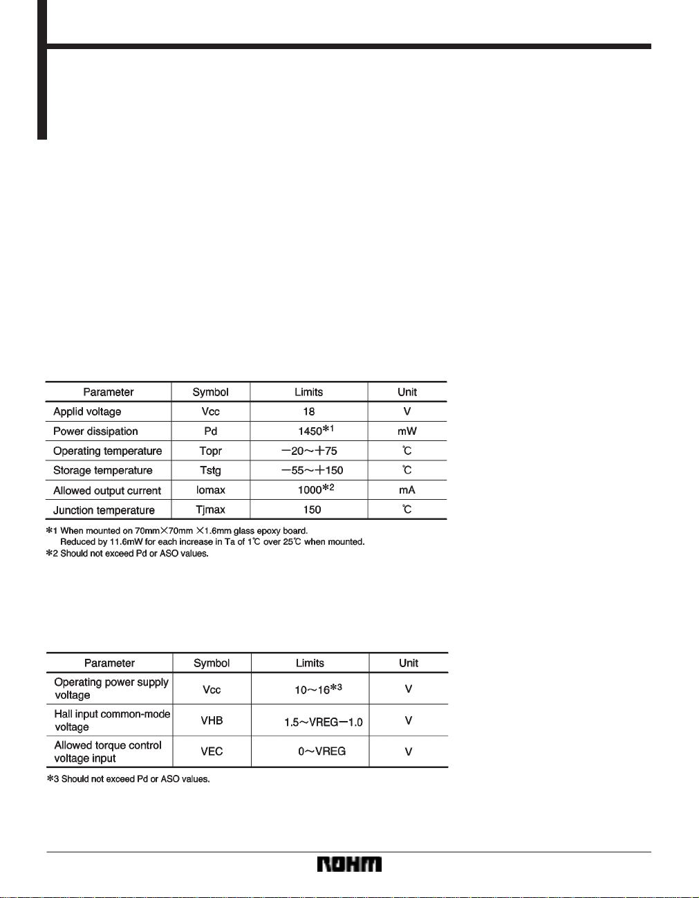
Absolute maximum ratings (Ta = 25C)
Recommended operating conditions (Ta = 25C)
754
Motor driver ICs BA6467FP-Y
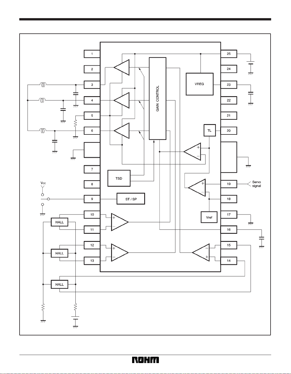
Block diagram
755
Motor driver ICs BA6467FP-Y
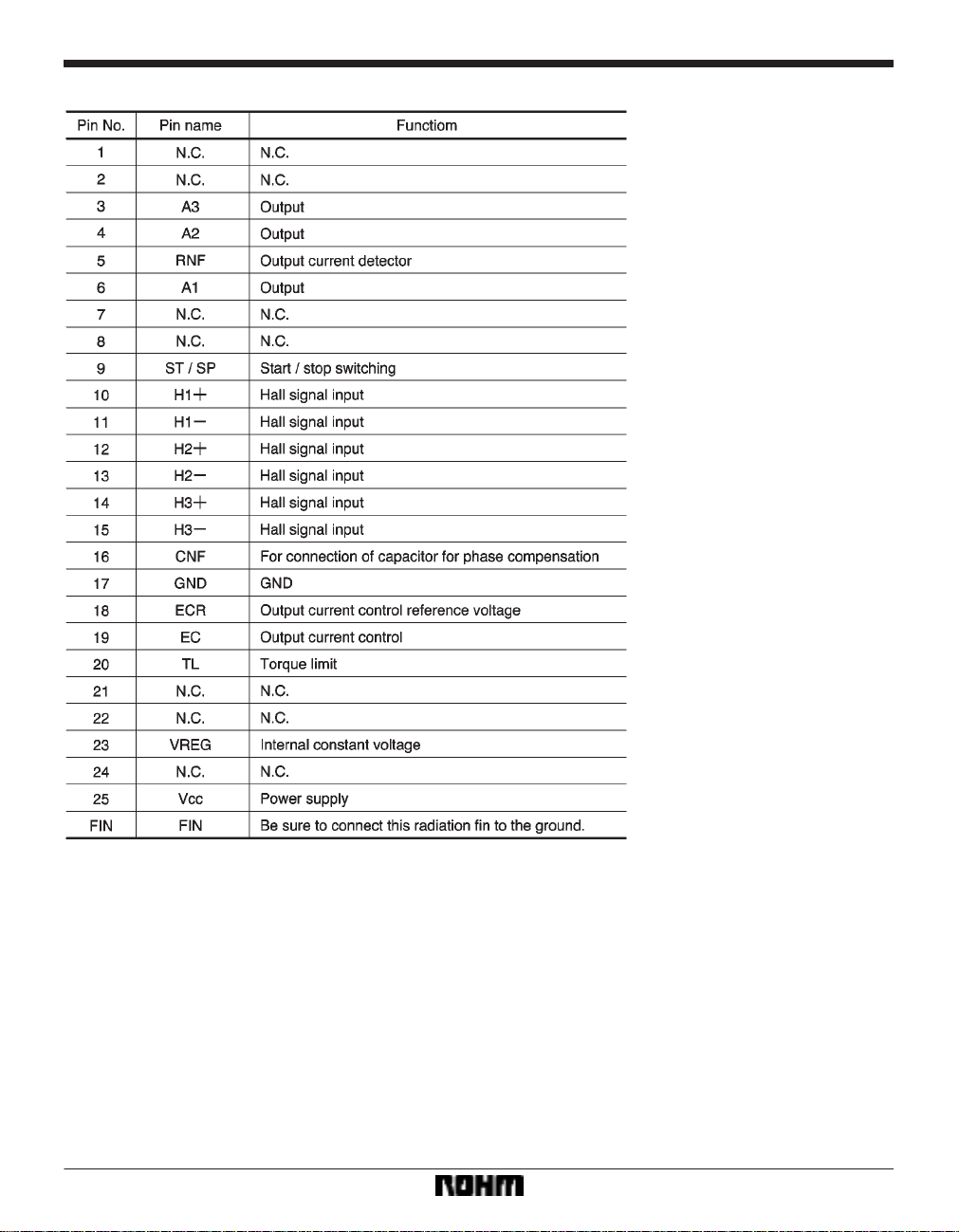
Pin descriptions
756

Motor driver ICs BA6467FP-Y
Input / output circuits
(1) Start / stop (ST / SP: pin 9)
(3) Torque control input (EC: pin19, ECR: pin 18)
(2) Torque limit (TL: pin20)
(4) Coil output (A1: pin 6, A2: pin4, A3: pin 3)
(5) Hall input (H1: pin10, H1–: pin 11, H2: pin 12,
H2–: pin 13, H3: pin 14, H3–: pin 15)
757

Motor driver ICs BA6467FP-Y
Electrical characteristics (unless otherwise noted, Ta = 25C, VCC = 12V)
758

Motor driver ICs BA6467FP-Y
Circuit operation
(1) Hall I / O
The 3-phase Hall signal is amplified in the hall amplifiers
and sent to the matrix circuit, where the signal is further
amplified and combined. After the signal is converted to
a current in the amplitude control circuit, the current is
supplied to the output driver, which then provides a motor
drive current. The phases of the Hall input signal, output
voltage, and output current are shown in Fig.1.
(2) Torque control pin
The output current can be controlled by adjusting the
voltage applied to the torque control pin.
(3) Start / stop pin
The motor is in the run mode when the pin input voltage
is 3.5V or more and in the standby mode (all output transistors are off) when the voltage is 1.2V or less.
(4) Power ground pin (RNF pin)
The power ground pin is the output stage ground pin.
Connect a resistor (0.5Ω recommended) between this
pin and the ground to monitor the output current.
(5) Phase compensation pin (CNF pin)
Connect a capacitor between this pin and V
put tends to oscillate.
CC if the out-
759

Motor driver ICs BA6467FP-Y
Application example
760

Motor driver ICs BA6467FP-Y
Operation notes
(1) Start / stop pin
The I / O equivalent circuit of the start / stop pin is shown
in Fig.4. The pin has a temperature dependence of
*7mV / C, and its resistance can vary ±30%. The volt-
age on this pin should be less than V
REG.
(2) Hall input
The input circuit of the Hall input pins is shown in Fig.5.
The Hall devices can be connected in either series or parallel. The input Hall signal should be within the range of
the Hall input common-mode voltage.
(3) Torque limit pin
The output current can be limited by applying a voltage
to the torque limit pin. Control is provided so that this pin
will have the same potential as the power ground pin
(RNF).
Note that there is a voltage offset on this pin. The RNFpin voltage is 0.325V when the TL-pin voltage is 0.4V
(typical) and the RNF-pin resistance is 0.5Ω. Note that
the voltage offset changes with RNF-pin resistance.
Connect the TL pin to V
REG (pin 23) when the TL pin is not
used.
(4) Thermal shutdown circuit (TSD)
The thermal shutdown circuit puts the coil outputs (A1,
A2, and A3) to the open state at the temperature of
175C (typical). There is an approximate 25C temperature hysteresis.
761

Motor driver ICs BA6467FP-Y
Electrical characteristic curves
External dimensions (Units: mm)
762
 Loading...