

Optical disc ICs
BTL driver for CD-ROMs
BA5972FP
The BA5972FP is a 4-channel BTL driver developed for use with CD-ROMs. A multi-purpose operational amplifier is
equipped in each channel to allow use in a variety of applications. Also, by applying independent power supplies for both
the pre-stage and power-stage, with the power-stage power supply further split into two so one power supply handles
two channels each, a highly efficient driver has been realized.
FApplications
CD-ROM, DVD-ROM, MD, and optical discs
FFeatures
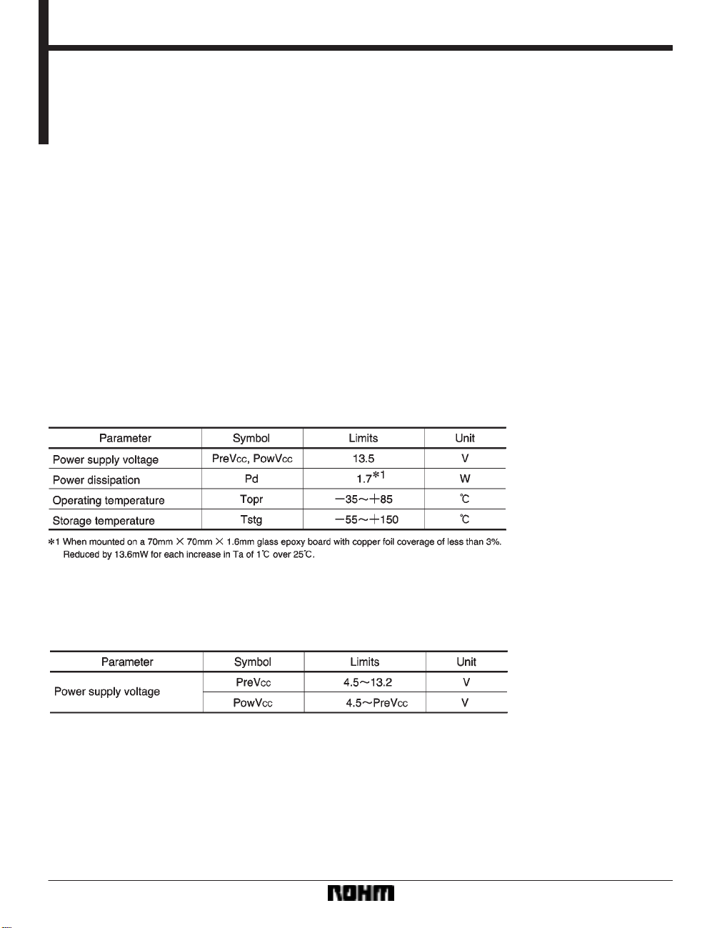
1) Wide dynamic range (V
= 8V, PowVCC = 5V, and RL = 8Ω).
2) Internal thermal shutdown circuit.
FAbsolute maximum ratings (Ta = 25_C)
OUT = 4V [Typ.] when PreVCC
3) Internal mute functions.
4) Internal standby functions.
FRecommended operating conditions (Ta = 25_C)
662
Optical disc ICs BA5972FP
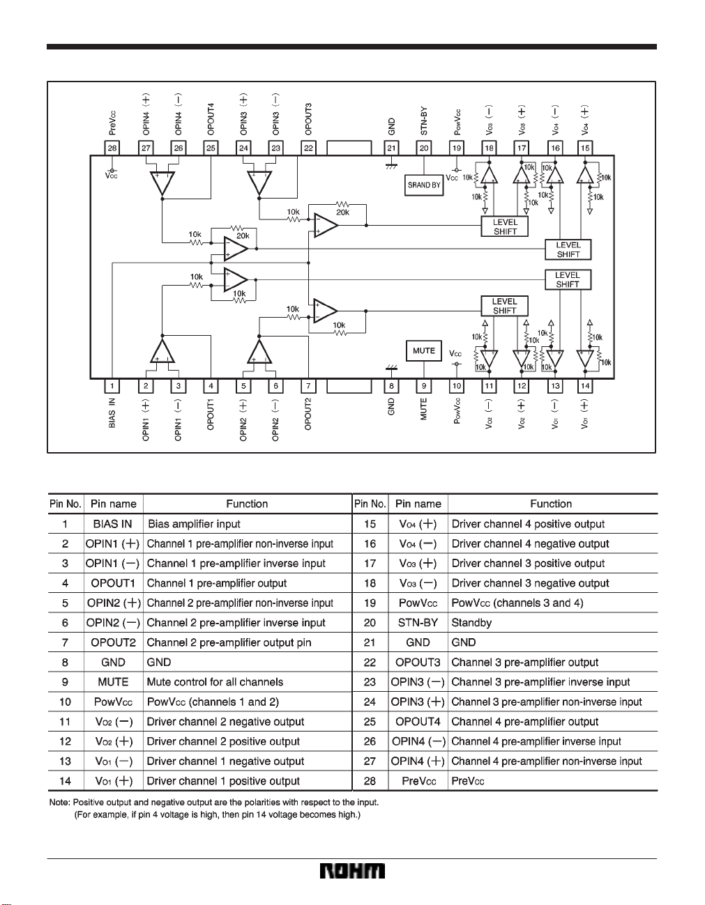
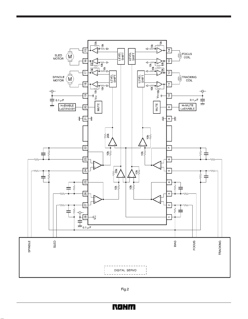
Block diagram
Pin descriptions
663
Optical disc ICs BA5972FP
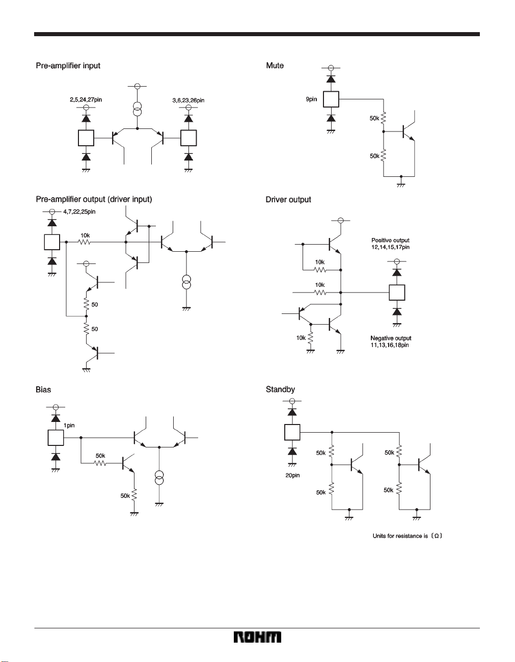
Input / output circuits
664
Optical disc ICs BA5972FP
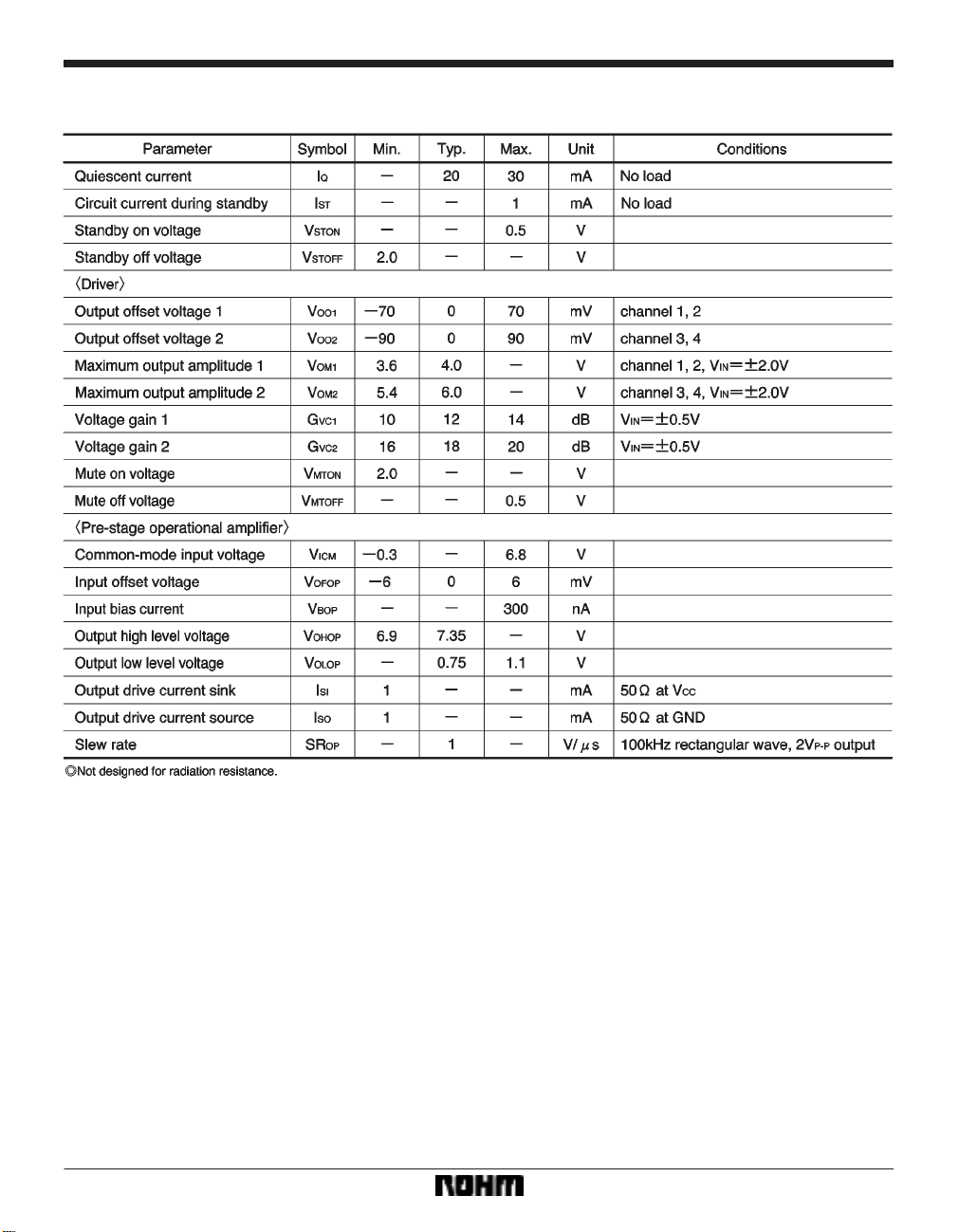
FElectrical characteristics (unless otherwise noted, T a = 25_C, PreVCC = 8V , PowVCC1 = 5V , PowVCC2 = 8V , BIAS = 2.5V,
FElectrical characteristics (R
L = 8Ω)
665

Optical disc ICs BA5972FP
Measurement circuit
666
Optical disc ICs BA5972FP
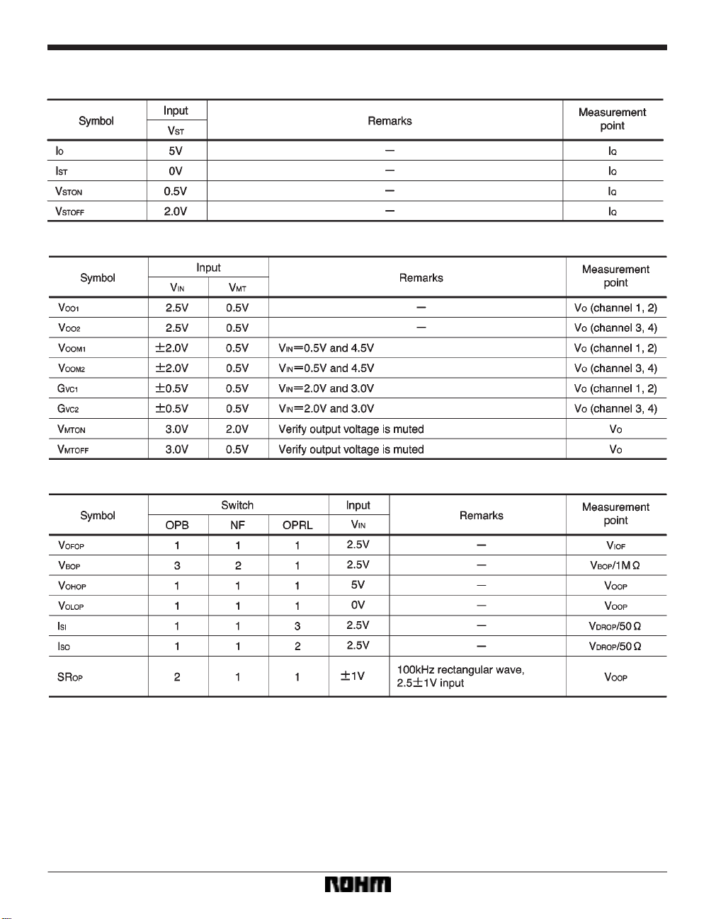
Measurement circuit switch table
(1) Circuit current and standby (V
MT = 0V, VIN = 2.5V, RL ! OFF, OPB ! 1, NF ! 1, OPRL ! 1)
(2) Driver block (V
ST = 5V, RL ! ON, OPB ! 1, NF ! 1, OPRL ! 1)
(3) Pre-stage operational amplifier block (V
ST = 5V, VMT = 0V, RL ! OFF)
667
Optical disc ICs BA5972FP
Application example
668
Optical disc ICs BA5972FP
FOperation notes
(1) The BA5972FP contains a thermal shutdown circuit.
When the chip temperature reaches 175_C (Typ.), the
output current is muted. If the chip temperature then
drops below 150_C (Typ.), then the mute is released.
(2) By having the mute pin (pin 7) voltage pulled up to
2.0V or greater, you can mute the output current for chan-
nels 1 and 4. For normal conditions, have pin 7 open or
at 0.5V or below.
(3) If the voltage of the bias pin (pin 1) drops below 1.4V
(Typ.), outputs are muted.
For normal conditions, have the voltage above 1.7V.
(4) If the power supply voltage drops below 3.8V (Typ.),
internal circuits turn off. If the power supply voltage then
rises to 4.0V (Typ.), the circuits turn on.
(5) If the voltage of the thermal shutdown, mute ON, or
bias pin drops, or if the power supply voltage drops, the
mute is activated; however, in these situations, only the
drivers are muted.
Also, the output pin voltage becomes the internal bias
voltage (approx. V
CC/2).
(6) If the standby pin voltage is open or 0.5V or below,
the circuit current enters the standby condition.
For normal operation, have the standby pin voltage
pulled up to 2.0V or greater.
(7) Connect a bypass capacitor (approx. 0.1µF) between the bases of the power supply pins of this IC.
(8) Even though the radiation fins are connected to
ground within the package, be sure to also connect them
to a ground externally as well.
(9) The application example will assure excellent results, but nevertheless, be sure to carefully check all
characteristics during use. During use with constants in
the external circuitry modified, be sure to leave a sufficient margin in order to take into consideration fluctuations in the static and transient characteristics of the external components and this IC.
Also, be aware that ROHM has not sufficiently performed
all confirmations regarding patent rights.
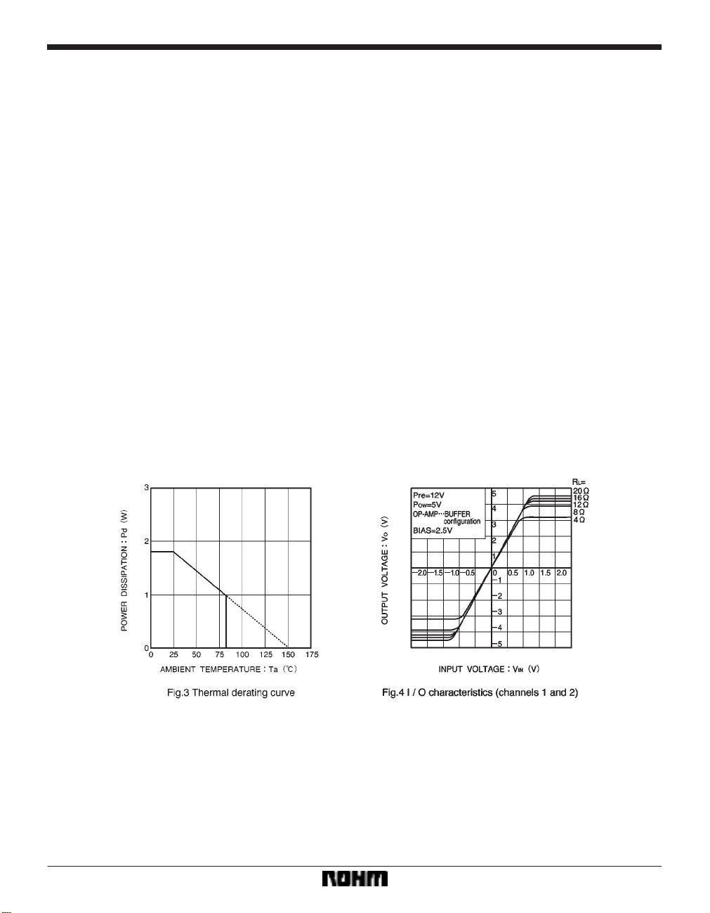
FElectrical characteristic curves
669

Optical disc ICs BA5972FP
External dimensions (Units: mm)
670
 Loading...