

Optical disc ICs
3-channel BTL driver for CD players
BA5933FP-Y
The BA5933FP-Y is a 3-channel BTL driver for CD player actuators and motors. This IC has an internal 5V regulator
and a standard operational amplifier, and comes in a HSOP 25-pin package, allowing for application miniaturization.
Applications
CD players and CD-ROM drives
Features
1) 3-channel BTL driver.
2) HSOP 25-pin power package allows for application
miniaturization.
3) Internal standby function.
4) Internal thermal shutdown circuit.
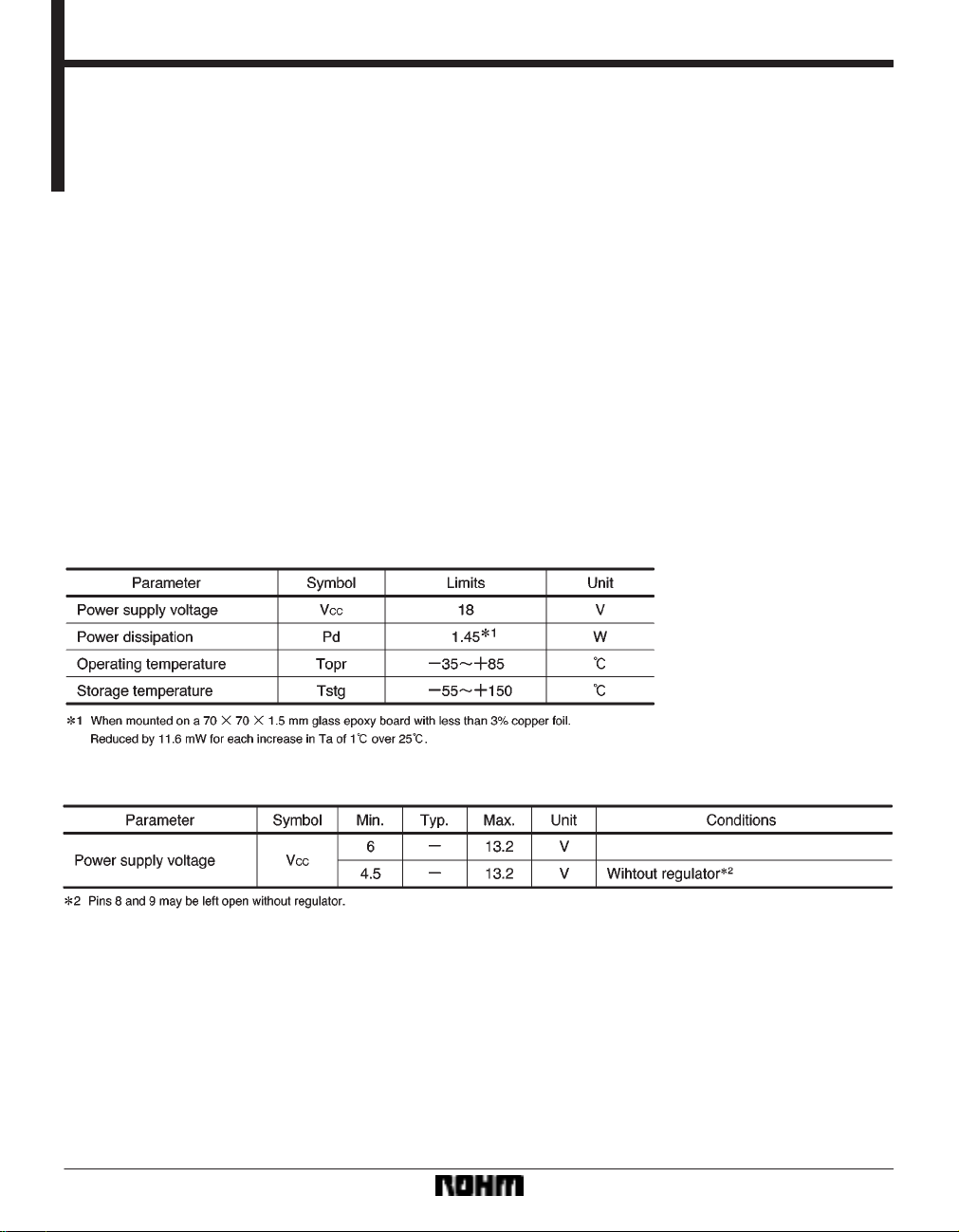
Absolute maximum ratings (Ta = 25C)
5) Gain is adjustable with an attached resistor.
6) Internal 5V regulator.
(requires attached PNP transistor)
7) Internal standard operational amplifier.
Recommended operating conditions (Ta = 25C)
176
Optical disc ICs BA5933FP-Y
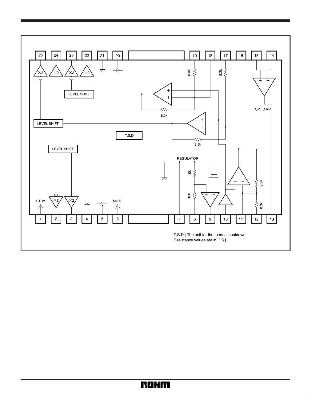
Block diagram
177
Optical disc ICs BA5933FP-Y
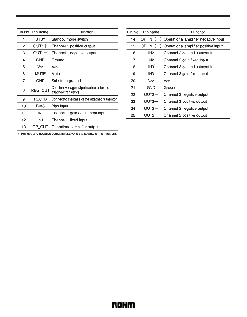
Pin descriptions
178

Optical disc ICs BA5933FP-Y
Pin equivalent circuit diagrams
179

Optical disc ICs BA5933FP-Y
Electrical characteristics (unless otherwise noted, Ta = 25C, VCC = 5V, BIAS = 2.5V, RL = 8Ω)
180

Optical disc ICs BA5933FP-Y
Measurement circuit
181

Optical disc ICs BA5933FP-Y
Application example
182

Optical disc ICs BA5933FP-Y
Operation notes
(1) The BA5933FP-Y has a thermal shutdown circuit.
The output current is muted when the chip temperature
rises above 175C (typically). When the chip temperature falls to 150C (typically), the driver circuit starts up
again.
(2) The output current can be muted by opening the
mute pin (pin 6) voltage or lowering it below 0.5V . During
normal use, pin 6 should be pulled up above 2.0V.
(3) The bias pin (pin10) is muted when lowered below
1.4V (typically). Make sure it stays above 1.6V during
normal use.
(4) Muting occurs during thermal shutdown, mute-on
operations or a drop in the bias pin voltage. In each case,
only the drivers are muted. During muting, the output pins
Electrical characteristic curves
remain at the internal bias voltage, roughly (V
(5) Connect the IC to a 0.1µF bypass capacitor between power supplies, at the base of the IC.
(6) The radiating fin is connected to the package’s internal GND, but should also be connected to an external
GND.
(7) The capacitor between regulator output (pin 8) and
GND also serves to prevent oscillation of the IC, so select
one with good temperature characteristics.
(8) The IC can be switched to the standby mode by
opening the standby mode switch (pin 1) voltage, or lowering it below 0.5V. During normal use, pin 1 should be
pulled up above 2.0V.
CC/2).
183

Optical disc ICs BA5933FP-Y
External dimensions (Units: mm)
184
 Loading...