

373
Audio ICs
3V / 35mW dual power amplifier
BA5204F
The BA5204F is a dual-channel power amplifier designed for 3V stereo headphone tape players. There is almost no
“pop” sound generated when the power is switched on and off, so this IC is ideal for headphone applications. Input coupling capacitors are not required, and only one filter capacitor is needed which helps reduce set size. In addition to operating off low voltage, the IC has low distortion, making it suitable for Hi-Fi applications. The circuit can operate down to
1.5V, and has excellent ripple rejection ratio, so it is not adversely influenced by the motor or tape transport systems.
Applications
3V compact cassette headphone stereos players, micro cassette players, and FM stereo radios
Features
1) Rated output of 35mW (RL = 32Ω) off a 3V power
supply.
2) Low “pop” noise when power is switched on and off.
3) Low quiescent current (13mA).
4) Excellent ripple rejection ratio (38dB).
5) Begins operating at 1.5V .
6) Low distortion (0.05% at P
O = 5mW).
7) Good voltage gain balance between channels.
8) Good channel separation (60dB Typ.).
9) Input coupling capacitors not required.
10) Symmetrical pin assignments facilitates PCB design.
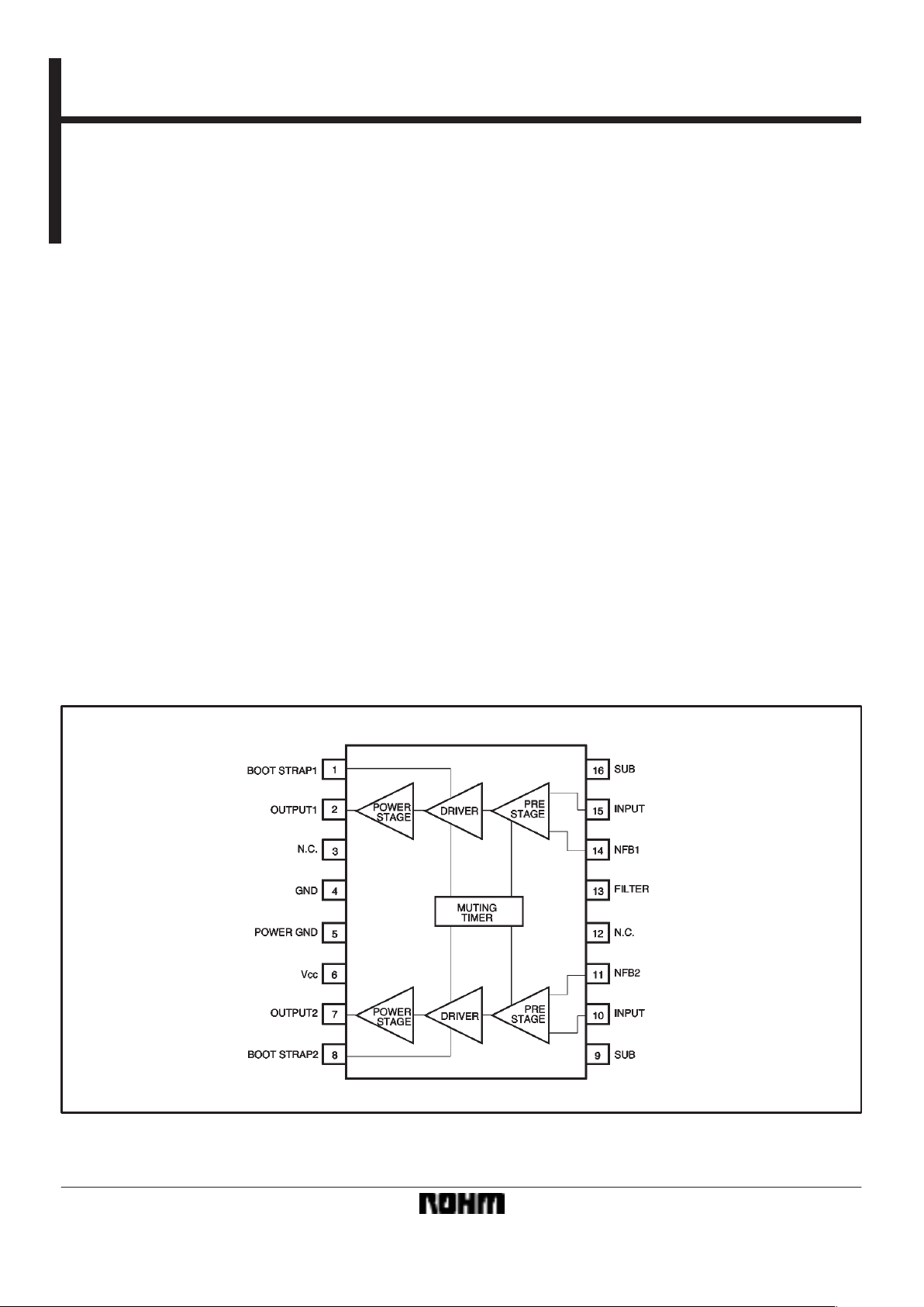
Block diagram
374
Audio ICs BA5204F
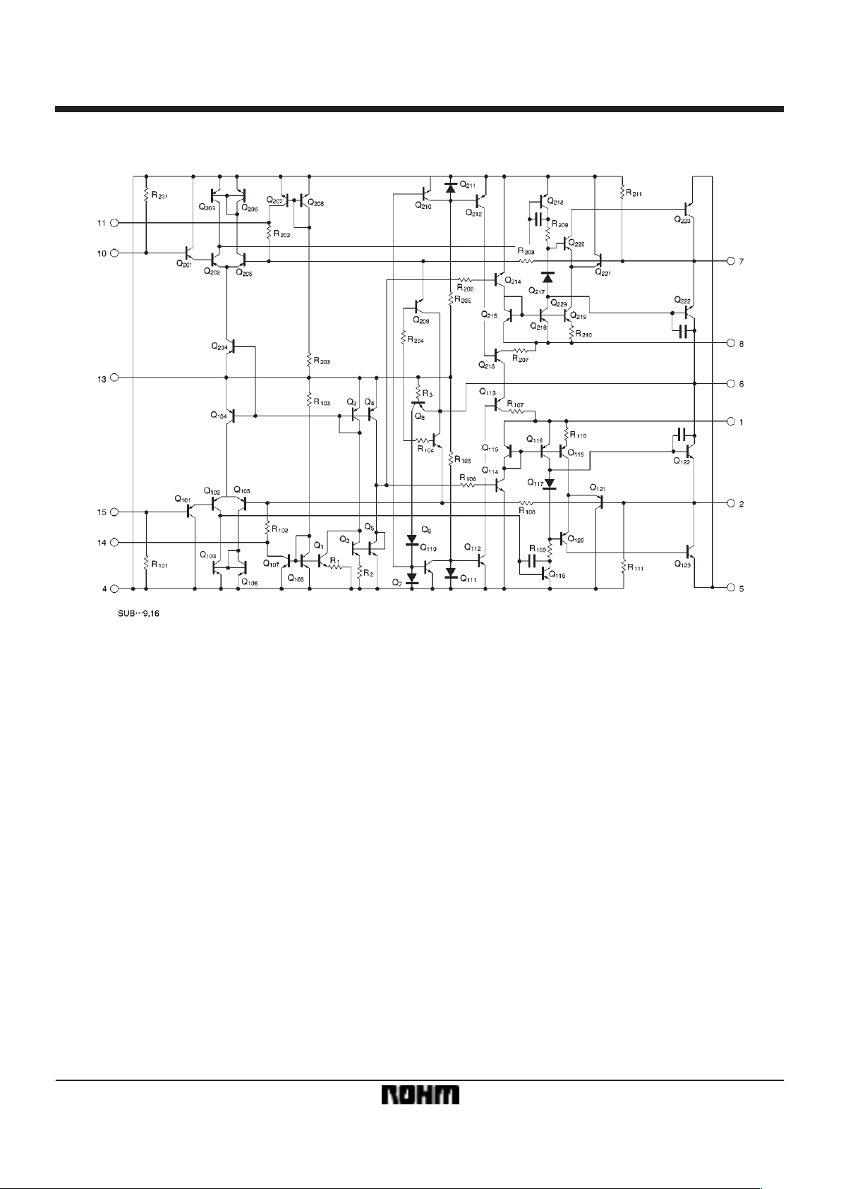
Internal circuit configuration
Circuit description (refer to the Internal Circuit diagram)
(1) Preamplifier Stage
The preamplifier is comprised of the level-shift transistor
Q
101, a differential amplifier (Q102 and Q105), and the active
load (Q
103 and Q106). The input is a PNP transistor that
does not require a coupling capacitor.
(2) Pre-drive stage
Q
118 is the pre-drive transistor. Q122 and Q120 form the
load.
(3) Power stage
Comprised of phase-inverting transistor Q
120, and power
transistors Q
122 and Q123.
(4) Idling current setting circuit
The idling current is controlled so that the difference between the V
BE of the power transistor Q122 and the VBE of
the phase-inverting transistor Q
120 is the same as the dif-
ference between the V
F of the constant-voltage diode
Q
117 and the VBE of Q121.
(5) Negative-feedback circuit
The closed-circuit gain with negative feedback is determined by R
108, R102, and the value of the resistor con-
nected to the NFB pin. Part of the gain setting resistance
is on the chip (R
102) to reduce variance between compo-
nents.
(6) “Pop” noise elimination circuit
The IC has an internal timing circuit (with switch for operation) to reduce the “pop” noise that occurs when power is applied.
375
Audio ICs BA5204F
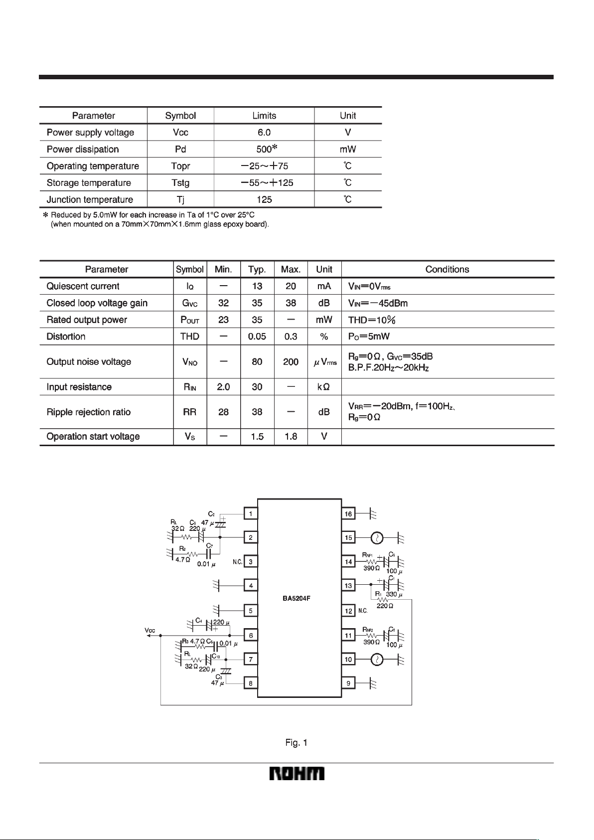
FAbsolute maximum ratings (Ta = 25_C)
FElectrical characteristics (Ta = 25_C, V
CC = 3V, f= 1kHz and RL = 32Ω)
FMeasurement circuit

1
2π
S C5 S (RNF1R102)
1
2π
S C6 S (RNF2R202)
376
Audio ICs BA5204F
FApplication example
FAttached components (Fig. 15)
C
1: filter capacitor
The recommended value is 330µF. If this is reduced too
much, the ripple rejection ratio will drop. This capacitor
also sets the muting time when power is applied. Reduce
the value of this capacitor if you wish to shorten the startup time. On the other hand, if you wish to reduce the
“pop” noise further, increase the value of this capacitor to
lengthen the startup time.
C
2 and C3: bootstrap capacitors
The recommended value is 47µF. If the capacitance is
too small, the IC will not be able to produce its rated power in the bass region and distortion will increase.
C
5 and C6: feedback circuit DC blocking capacitors
These capacitors and RNF set the bass cutoff frequency .
ch
1
G G G G
fLC1 =
ch
2
G G G G
fLC2 =
R
NF1 and RNF2 determine the amount of feedback for the
feedback circuit. These resistors determine the closedcircuit voltage gain (G
VC).
C
7 and C8: depending on the PCB design, and output cir-
cuit wiring, feedback may be applied to the IC’s internal
circuits and cause high-frequency oscillation. These capacitors prevent this from happening. They also increase
the amount of design freedom with regard to the output
wiring and PCB artwork. Design the PCB so that the
length of the wiring from ch1 and ch2 to capacitors and
from the capacitors to GND is as short as possible. Mylar
capacitors of about 0.01µF are appropriate for this application, although active capacitors may also be used.
The residual impedance and resonant frequency will differ depending on the type of capacitor and therefore have
some influence on the effectiveness.
C
9 and C10: output coupling capacitors
The recommended value is 220µF. If the capacitance is
too small, the IC will not be able to produce its rated power in the treble region and distortion will increase.

377
Audio ICs BA5204F
Electrical characteristics curves

378
Audio ICs BA5204F

External dimensions (Units: mm)
379
Audio ICs BA5204F
 Loading...