

Page 1
Audio Accessory IC Series
Ground Isolation
Amplifier
BA3121F, BA3123F
No.09092EAT01
●Description
The BA3121F/BA3123F are ground isolation amplifiers deve loped for use in car audio applications.
This IC efficiently eliminate problems caused by wiring resistance, and remove noise generated by the electrical devices
used in automobiles. The capacitance values of the external capacitors required for the ICs are small to allow compact
and reliable set design.
●Features
1) Large capacitors not required
2) High common-mode rejection ratio (57dB typ. at f = 1kHz).
3) Low noise (VNO = 3.5μVrms T yp.).
4) Low distortion (THD = 0.002% Typ.).
5) Two channels.
●Applications
Car audio systems
●Line up matrix
BA3121F BA3123F
Operation temperature
●Absolute maximum ratings (Ta = 25C)
Parameter Symbol Limits Unit
Power supply voltage Vcc 18 V
Power dissipation Pd 450* mW
Operation
temperature
Storage temperature Tstg -55~+125 ℃
*Reduced by 4.5mW in Ta of 1C over 25C.
●Recommended operating conditions (Ta = 25C)
Parameter Symbol Min. Typ. Max. Unit
Power supply voltage Vcc 4 12 18 V
BA3121F
BA3123F -40~+85 ℃
-30~+85C -40~+85C
Topr
-30~+85 ℃
www.rohm.com
1/8
© 2009 ROHM Co., Ltd. All rights reserved.
2009.08 - Rev.A
Page 2
BA3121F, BA3123F
●Electrical characteristics (unless otherwise noted, Ta = 25C, VCC = 12V, f = 1kHz, Rg = 1.8k)
Parameter Symbol Min. Typ. Max. Unit Conditions
Quiescent current IQ 5.6 9.0 14.0 mA VIN=0V
Output noise voltage VNO - 3.5 8.0 μV
BPF=20Hz-20kHz
rms
rms
Voltage gain GV -1.5 -0.04 1.5 dB VO=-10dBm, Rg=0Ω
Maximum output voltage VOM 1.8 2.0 - V
THD=0.1%, Vcc=8V
rms
Total harmonic distortion THD - 0.002 0.02 % VO=0.7V
Common-mode rejection ratio CMRR 41 57 - dB
Common-made voltage VCM 2.5 3.75 - V
Ripple rejection ratio RR 72 80 - dB
Channel separation CS - 82 - dB
Vcc=8V,CMRR=40dB
rms
fRR=100Hz,VRR=-10dBm,
=0Ω
R
g
VIN=-10dBm,
Rg=1.8kΩ/OPEN
Slew rate SR - 2.0 - V/μS
Input resistance RIN 44 55 66 kΩ
◎Not designed for radiation resistance
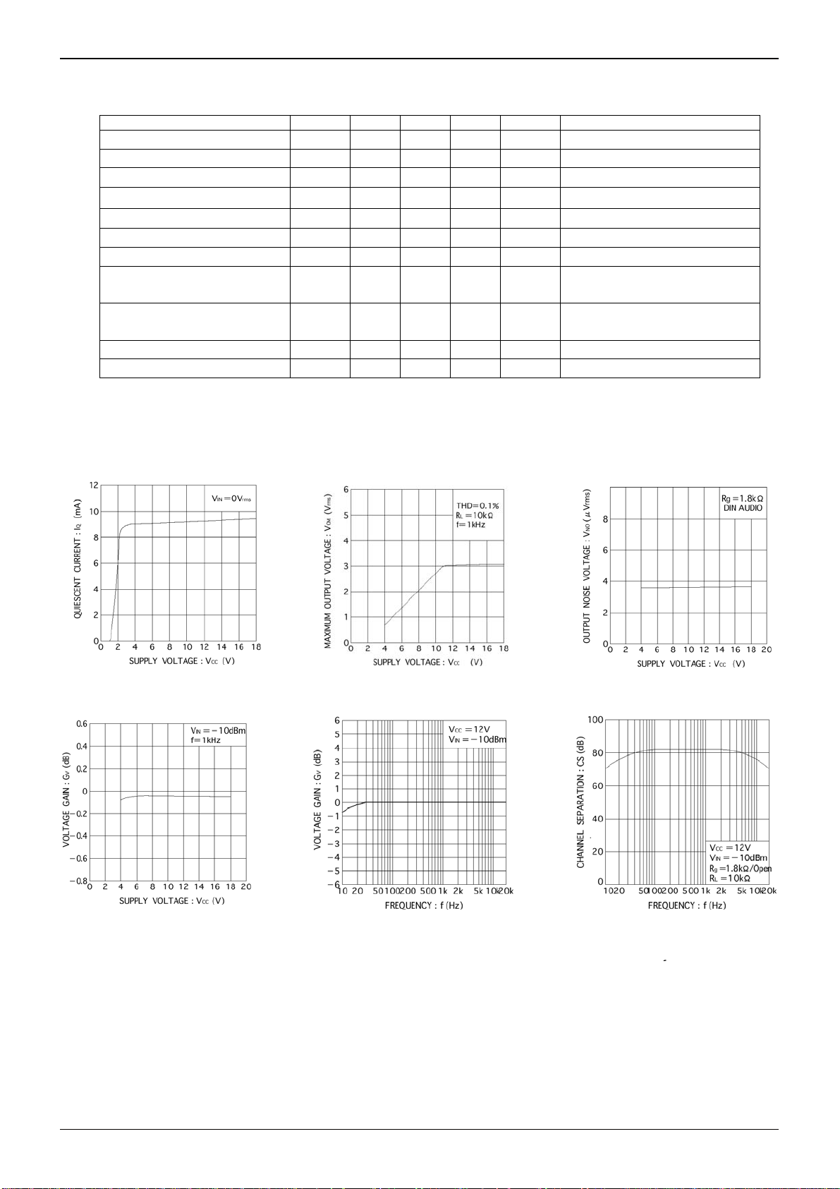
●Electrical characteristics curves
Fig.1 Quiescent current
vs. power supply voltage
Fig.2 Maximum output voltage
vs. power supply voltage
Fig.3 Output noise voltage
vs. power supply voltage
Fig.4 Voltage gain
vs. power supply voltage
Fig.5 Voltage gain vs. frequency
Fig.6 Channel separation
rms
Technical Note
www.rohm.com
2/8
© 2009 ROHM Co., Ltd. All rights reserved.
2009.08 - Rev.A
Page 3
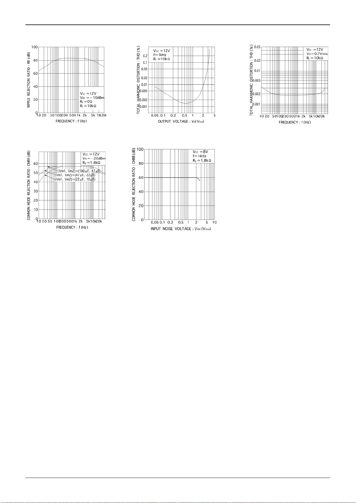
BA3121F, BA3123F
Fig.7 Ripple rejection ratio
Fig.10 Common-mode rejection ratio
vs. frequency
vs. frequency
Fig.8 Total harmonic distortion
vs. output voltage
Fig.11Common-mode rejection ration
vs. input voltage
Technical Note
Fig.9 Total harmonic distortion
vs. frequency
www.rohm.com
3/8
© 2009 ROHM Co., Ltd. All rights reserved.
2009.08 - Rev.A
Page 4

BA3121F, BA3123F
●Measurement circuits
Technical Note
BA3121F / BA3123F
Fig.12
www.rohm.com
4/8
© 2009 ROHM Co., Ltd. All rights reserved.
2009.08 - Rev.A
Page 5

BA3121F, BA3123F
●Block Diagram
Technical Note
Fig.13
www.rohm.com
5/8
© 2009 ROHM Co., Ltd. All rights reserved.
2009.08 - Rev.A
Page 6

BA3121F, BA3123F
●Circuit operation
Fig.14 Flow of noise in car audio systems
Car audio systems are earthed to the car body, and for
this reason, electrical noise generated by the car electrics
can enter the power amplifier input via the chassis,
and become audible.
The BA3121F/BA3123F makes use of the common-mode
rejection characteristics of an operational amplifier to eliminate
this noise. Without the BA3121F/BA3123F noise enters
the power amplifier input directly, when used, the CMMR of
operational amplifiers 1-A and 2-A eliminates the noise.
Principles of noise elimination:
To obtain the output voltage (eO)
Fig.15 The principle of noise rejection
Technical Note
With the BA3121F/BA3123F, the elimination level of
the noise is expressed
as: CMMR = 20log (e
Therefore, CMRR ≧ 41dB can be guaranteed.
From ① and ②
)(eI = e1 = e2)
0/eI
Ideally, if R1R4 = R2R3, and e1 = e2, the noise voltage will
become zero. However, due to mismatching between the
resistors, difference in the noise voltages (e1 and e2), and
tolerances in the operational amplifier, a noise voltage
does result.
www.rohm.com
6/8
© 2009 ROHM Co., Ltd. All rights reserved.
2009.08 - Rev.A
Page 7

BA3121F, BA3123F
●Applications
Fig.16
●Cautions on use
(1) Numbers and data in entries are representative design values and are not guaranteed values of the items.
(2) Although we are confident in recommending the sample application circuits, carefully check their characteristics further
when using them. When modifying externally attached component constants before use, determine them so that they
have sufficient margins by taking into account variations in externally attached components and the Rohm LSI, not only
for static characteristics but also including transient characteristics.
(3) Absolute maximum ratings
If applied voltage, operating temperature range, or other absolute maximum ratings are exceeded, the LSI may be
damaged. Do not apply voltages or temperatures that exceed the absolute maximum ratings. If you think of a case in
which absolute maximum ratings are exceeded, enforce fuses or other physica l safety measures and investigate how
not to apply the conditions under which absolute maximum ratings are e xceeded to the LSI.
(4) GND potential
Make the GND pin voltage such that it is the lowest voltage even when operating below it. Actually confirm that the
voltage of each pin does not become a lower voltage than the GND pin, including transient phenomena.
(5) Thermal design
Perform thermal design in which there are adequate margins by taking into account the allowable po wer dissipation in
actual states of use.
(6) Shorts between pins and misinstallation
When mounting the LSI on a board, pay adequate attention to orientation and plac ement discrepancies of the LSI. If it
is misinstalled and the power is turned on, the LSI may be damaged. It also ma y be damaged if it is shorted by a
foreign substance coming between pins of the LSI or between a pin and a power supply or a pin and a GND.
(7) Operation in strong magnetic fields
Adequately evaluate use in a strong magnetic field, since there is a possibility of malfunction.
(8) The capacitors of 2pin (Vm
Maintaining this ratio will not cause ripple removal rate to reduce significantly even if the capacitance reduces to a half.
(9) Setting the capacitor to the double or half will make the CMRR in the low range to +6dB or -6dB respectively (Fig. 10)
), and 6pin (Vm2) should maintain the ratio of 2:1 for ripple removal characteristics.
1
Technical Note
www.rohm.com
7/8
© 2009 ROHM Co., Ltd. All rights reserved.
2009.08 - Rev.A
Page 8

BA3121F, BA3123F
●Ordering part number
B A 3 1 2 1 F - E 2
Part No. Part No.
SOP8
4.4±0.2
6.2±0.3
1.5±0.1
5.0±0.2
(MAX 5.35 include BURR)
7
6
438251
0.595
0.11
1.27
0.42±0.1
3121:
Operation temperature
-30~85C
3123:
Operation temperature
-40~85C
+
6
°
4
°
−4°
0.3MIN
0.9±0.15
+0.1
0.17
-
0.05
S
(Unit : mm)
Package
F: SOP8
<Tape and Reel information>
Embossed carrier tapeTape
Quantity
Direction
of feed
2500pcs
E2
The direction is the 1pin of product is at the upper left when you hold
()
reel on the left hand and you pull out the tape on the right hand
Reel
Technical Note
Packaging and forming specification
E2: Embossed tape and reel
1pin
Order quantity needs to be multiple of the minimum quantity.
∗
Direction of feed
www.rohm.com
8/8
© 2009 ROHM Co., Ltd. All rights reserved.
2009.08 - Rev.A
Page 9

Notes
No copying or reproduction of this document, in part or in whole, is permitted without the
consent of ROHM Co.,Ltd.
The content specied herein is subject to change for improvement without notice.
The content specied herein is for the purpose of introducing ROHM's products (hereinafter
"Products"). If you wish to use any such Product, please be sure to refer to the specications,
which can be obtained from ROHM upon request.
Examples of application circuits, circuit constants and any other information contained herein
illustrate the standard usage and operations of the Products. The peripheral conditions must
be taken into account when designing circuits for mass production.
Great care was taken in ensuring the accuracy of the information specied in this document.
However, should you incur any damage arising from any inaccuracy or misprint of such
information, ROHM shall bear no responsibility for such damage.
The technical information specied herein is intended only to show the typical functions of and
examples of application circuits for the Products. ROHM does not grant you, explicitly or
implicitly, any license to use or exercise intellectual proper ty or other rights held by ROHM and
other par ties. ROHM shall bear no responsibility whatsoever for any dispute arising from the
use of such technical information.
Notice
The Products specied in this document are intended to be used with general-use electronic
equipment or devices (such as audio visual equipment, ofce-automation equipment, communication devices, electronic appliances and amusement devices).
The Products specied in this document are not designed to be radiation tolerant.
While ROHM always makes efforts to enhance the quality and reliability of its Products, a
Product may fail or malfunction for a variety of reasons.
Please be sure to implement in your equipment using the Products safety measures to guard
against the possibility of physical injur y, re or any other damage caused in the event of the
failure of any Product, such as derating, redundancy, re control and fail-safe designs. ROHM
shall bear no responsibility whatsoever for your use of any Product outside of the prescribed
scope or not in accordance with the instruction manual.
The Products are not designed or manufactured to be used with any equipment, device or
system which requires an extremely high level of reliability the failure or malfunction of which
may result in a direct threat to human life or create a risk of human injury (such as a medical
instrument, transpor tation equipment, aerospace machiner y, nuclear-reactor controller,
fuel-controller or other safety device). ROHM shall bear no responsibility in any way for use of
any of the Products for the above special purposes. If a Product is intended to be used for any
such special purpose, please contact a ROHM sales representative before purchasing.
If you intend to export or ship overseas any Product or technology specied herein that may
be controlled under the Foreign Exchange and the Foreign Trade Law, you will be required to
obtain a license or permit under the Law.
www.rohm.com
© 2009 ROHM Co., Ltd. All rights reserved.
Thank you for your accessing to ROHM product informations.
More detail product informations and catalogs are available, please contact us.
ROHM Customer Support System
http://www.rohm.com/contact/
R0039
A
 Loading...