

BA178M!!T / BA178M!!FP series
Regulator ICs
Standard 78M series, 3-pin regulator
BA178M!!
The BA178M!!T and BA178M!!FP series are 3-pin, fixed positive output voltage regulators. These regulators are
used to provide a stabilized output voltage from a fluctuating DC input voltage.
There are 11 fixed output voltages, as follows : 5V, 6V, 7V, 8V, 9V, 10V, 12V, 15V, 18V, 20V, and 24V.
The maximum current capacity is 0.5A for each of the above voltages.
""""
Application
Constant voltage power supply
""""Features
1) Built-in overcurrent protection circuit and thermal shutdown circuit.
2) Excellent ripple regulation.
3) Available in TO-220FP and TO252-3 packages, to meet wide range of applications.
4) Compatible with other manufacturers' regulators.
5) Richly diverse lineup. (5V, 6V, 7V, 8V, 9V, 10V, 12V, 15V, 18V, 20V, 24 V)
""""
Product codes
Output voltage (V) Product No. Output voltage (V) Product No.
512
615
718
820
924
10 −−
!!T / BA178M!!
!!!!
BA178M05T / FP
BA178M06T / FP
BA178M07T / FP
BA178M08T / FP
BA178M09T / FP
BA178M10T / FP
!!FP series
!!!!
BA178M12T / FP
BA178M15T / FP
BA178M18T / FP
BA178M20T / FP
BA178M24T / FP
Regulator ICs
""""
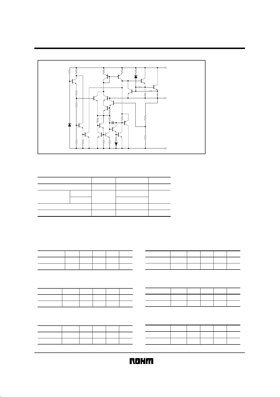
Internal circuit configuration diagram
R
4
R
10
Q
12
R
5
R
6
D
1
R
7
Q
13
R
1
Q
18
Q
1
Q
14
R
22
BA178M!!T / BA178M!!FP series
(1)
R
8
Q
Q
R
10
R
9
R
Q
8
Q
10
Q
6
5
R
15
R
R
2
C
1
7
Q
4
Q
2
R
R
3
D
13
D
2
Q
9
Q
16
Q
11
Q
3
14
3
Q
16
15
R
12
R
21
R
17
R
20
R
19
INPUT
Q
17
R
11
(3)
OUTPUT
(2)
COMMON
""""
Absolute maximum ratings
(Ta=25°C)
^Common specifications for BA178M!!T / FP seriesp
Parameter Symbol Limits Unit
Applied voltage V
Power dissipation W
TO220FP
TO252−3
Operating temperature Topr
Storage temperature Tstg
Reduced by 16 mW (TO220FP) and 8 mW (TO252-3) for each increase in Ta of 1°C over 25
∗
(without heat sink).
IN 35 V
∗
Pd
2.0
1.0
∗
−40~+85
−55
~+
150
""""Recommended operating conditions (Ta=25°C)
BA178M05T / FP
Parameter Symbol Min. Typ. Max. Unit
V
Input voltage 7.5 −
IN
I
O
− 0.5 AOutput current
20
−
BA178M07T / FP
Parameter Symbol Min. Typ. Max. Unit
V
IN
Input voltage
Output current
I
9.5 − 22 V
O
−−0.5 A
V
BA178M06T / FP
Parameter Symbol Min. Typ. Max. Unit
Input voltage
Output current
BA178M08T / FP
Parameter Symbol Min. Typ. Max. Unit
Input voltage
Output current
°C
°C
°C
V
IN
8.5 − 21 V
I
O
V
I
−−0.5 A
10.5 − 23 V
IN
−−0.5 A
O
BA178M09T / FP
Parameter Symbol Min. Typ. Max. Unit
IN
Input voltage
Output current
V
11.5 − V
I
O
−−0.5 A
24
BA178M10T / FP
Parameter Symbol Min. Typ. Max. Unit
V
IN
Input voltage
Output current
12.5 − 25 V
IO
−−0.5 A
Regulator ICs
BA178M!!T / BA178M!!FP series
BA178M12T / FP
Parameter Symbol Min. Typ. Max. Unit
Input voltage
Output current
V
IO
15 − 27 V
IN
−−0.5 A
BA178M18T / FP
Parameter Symbol Min. Typ. Max. Unit
Input voltage
Output current
V
IO
21 − 33 V
IN
−−0.5 A
BA178M15T / FP
Parameter Symbol Min. Typ. Max. Unit
V
IN
Input voltage
Output current
17.5 − 30 V
I
O
−−0.5 A
BA178M20T / FP
Parameter Symbol Min. Typ. Max. Unit
Input voltage
Output current
V
IO
23 − 33 V
IN
−−0.5 A
BA178M24T / FP
Parameter Symbol Min. Typ. Max. Unit
V
Input voltage
Output current
IN 27 − 33 V
I
O −−0.5 A
""""Electrical characteristics
<BA178M05T / FP individual specifications> (unless otherwise noted, Ta=25°C, V
Parameter Symbol Min. Typ. Max. Unit Conditions
Output voltage 1 V
Output voltage 2 V
Input stability 1 Reg.I
Input stability 2 Reg.I
Ripple rejection ratio R.R. 62 78 − dB Fig.2
Load regulation 1 Reg.L
Load regulation 2 Reg.L
Temperature coefficient of output voltage T
Output noise voltage V
Minimum I/O voltage differential V
Bias current I
Bias current change 1 I
Bias current change 2 I
Peak output current I
Output short-circuit current I
O1
4.8 5.0 5.2 V I
O2
4.75 − 5.25 V Fig.1
1
− 3 100 mV Fig.1
2
− 1 50 mV Fig.1
1
− 20 100 mV I
2
− 10 50 mV I
CVO
b1
b2
O−P
OS
−−1.0 − Fig.1
n
− 40 −µVf=10Hz~100kHz Fig.3
d
− 2.0 − VI
b
− 4.5 6.0 mA I
−−0.5 mA I
−−0.8 mA Fig.5
− 875 − mA T
− 0.4 − AV
mV/
°C
=10V, IO=350mA)
IN
O
=
350mA Fig.1
IN
=
7.5~20V, I
V
IN
=
7~25V, I
V
V
IN
=
8~12V, I
e
IN
=
1Vrms, f=120Hz, I
O
=
5~500mA Fig.1
O
=
5~200mA Fig.1
I
O
=
5mA, T
O
=
500mA Fig.4
O
=
0mA Fig.5
O
=
5~350mA Fig.5
V
IN
=
8~25V, I
j
=
25
°C
IN
=
25V Fig.6
O
O
j
=
0~125
O
O
=
5~350mA
=
200mA
=
200mA
°C
=
200mA
O
=
100mA
Measurement
circuit
Fig.1
BA178M!!T / BA178M!!FP series
Regulator ICs
<BA178M06T / FP individual specifications> (unless otherwise noted, Ta=25°C, VIN=11V, IO=350mA)
Parameter Symbol Min. Typ. Max. Unit Conditions
V
O1
Output voltage 1
Output voltage 2
Input stability 1
Input stability 2
Ripple rejection ratio
Load regulation 1
Load regulation 2
Temperature coefficient of output voltage
Output noise voltage
Minimum I/O voltage differential
Bias current
Bias current change 1
Bias current change 2
Peak output current
Output short-circuit current
Reg.I
Reg.I
Reg.L
Reg.L
5.75 6.0 6.25 V IO=350mA
V
O2
5.7 − 6.3 V
1
− 3 100 mV
2
− 150mV
R.R. 60 74 − dB
1
− 20 120 mV IO=5~500mA
2
− 10 60 mV IO=5~200mA
CVO
T
V
V
I
I
I
O−P
I
OS
−−0.5 −
n
− 60 −µVf=10Hz~100kHz
d
− 2.0 − VIO=500mA
b
− 4.5 6.0 mA IO=0mA
I
b1
−−0.5 mA IO=5~350mA
b2
−−0.8 mA
mV/
− 875 − mA Tj=25
− 0.4 − AVIN=25V
IN
=8.5~21V, IO=5~350mA
V
IN
=8~25V, IO=200mA
V
V
IN
=9~25V, IO=200mA
e
IN
=1Vrms, f=120Hz, IO=100mA
I
O
=5mA, Tj=0~125
°C
VIN=9~25V, IO=200mA
°C
°C
Measurement
circuit
Fig.1
Fig.1
Fig.1
Fig.1
Fig.2
Fig.1
Fig.1
Fig.1
Fig.3
Fig.4
Fig.5
Fig.5
Fig.5
Fig.1
Fig.6
<BA178M07T / FP individual specifications> (unless otherwise noted, Ta=25°C, VIN=13V, IO=350mA)
Parameter Symbol Min. Typ. Max. Unit Conditions
V
O1
Output voltage 1
Output voltage 2
Input stability 1
Input stability 2
Ripple rejection ratio
Load regulation 1
Load regulation 2
Temperature coefficient of output voltage
Output noise voltage
Minimum I/O voltage differential
Bias current
Bias current change 1
Bias current change 2
Peak output current
Output short-circuit current
Reg.I
Reg.I
R.R. 57 71 − dB
Reg.L
Reg.L
T
I
6.7 7.0 7.3 V IO=350mA
V
O2
6.65 − 7.35 V
1
− 4 100 mV
2
− 150mV
1
− 20 140 mV IO=5~500mA
2
− 10 70 mV IO=5~200mA
CVO
−−0.5 −
V
n
− 70 −µVf=10Hz~100kHz
d
V
I
I
O−P
I
− 2.0 − VIO=500mA
b
− 4.5 6.0 mA IO=0mA
I
b1
−−0.5 mA IO=5~350mA
b2
−−0.8 mA
− 875 − mA Tj=25
OS
− 0.4 − AVIN=25V
IN
=9.5~22V, IO=5~350mA
V
IN
=9~25V, IO=200mA
V
V
IN
=10~25V, IO=200mA
e
IN
=1Vrms, f=120Hz, IO=100mA
I
O
=5mA, Tj=0~125
°C
mV/
VIN=10~25V, IO=200mA
°C
°C
Measurement
circuit
Fig.1
Fig.1
Fig.1
Fig.1
Fig.2
Fig.1
Fig.1
Fig.1
Fig.3
Fig.4
Fig.5
Fig.5
Fig.5
Fig.1
Fig.6

BA178M!!T / BA178M!!FP series
Regulator ICs
<BA178M08T / FP individual specifications> (unless otherwise noted, Ta=25°C, VIN=14V, IO=350mA)
Parameter Symbol Min. Typ. Max. Unit Conditions
V
O1
Output voltage 1
Output voltage 2
Input stability 1
Input stability 2
Ripple rejection ratio
Load regulation 1
Load regulation 2
Temperature coefficient of output voltage
Output noise voltage
Minimum I/O voltage differential
Bias current
Bias current change 1
Bias current change 2
Peak output current
Output short-circuit current
V
Reg.I
Reg.I
R.R. 56 69 − dB
Reg.L
Reg.L
T
O−P
I
I
7.7 8.0 8.3 V IO=350mA
O2
7.6 − 8.4 V
1
− 4 100 mV
2
− 150mV
1
− 20 160 mV IO=5~500mA
2
− 10 80 mV IO=5~200mA
V
V
I
I
CVO
I
b1
b2
−−0.5 −
n
− 80 −µVf=10Hz~100kHz
d
− 2.0 − VIO=500mA
b
− 4.5 6.0 mA IO=0mA
−−0.5 mA IO=5~350mA
−−0.8 mA
− 875 − mA Tj=25
OS
− 0.4 − AVIN=25V
V
IN
=10.5~23V, IO=5~350mA
V
IN
=10.5~25V, IO=200mA
V
IN
=11~12V, IO=200mA
e
IN
=1Vrms, f=120Hz, IO=100mA
mV/
I
O
=5mA, Tj=0~125
°C
VIN=10.5~25V, IO=200mA
°C
°C
Measurement
circuit
Fig.1
Fig.1
Fig.1
Fig.1
Fig.2
Fig.1
Fig.1
Fig.1
Fig.3
Fig.4
Fig.5
Fig.5
Fig.5
Fig.1
Fig.6
<BA178M09T / FP individual specifications> (unless otherwise noted, Ta=25°C, VIN=15V, IO=350mA)
Parameter Symbol Min. Typ. Max. Unit Conditions
V
O1
Output voltage 1
Output voltage 2
Input stability 1
Input stability 2
Ripple rejection ratio
Load regulation 1
Load regulation 2
Temperature coefficient of output voltage
Output noise voltage
Minimum I/O voltage differential
Bias current
Bias current change 1
Bias current change 2
Peak output current
Output short-circuit current
Reg.I
Reg.I
R.R. 56 67 − dB
Reg.L
Reg.L
T
I
8.6 9.0 9.4 V IO=350mA
V
O2
8.55 − 9.45 V
1
− 4 100 mV
2
− 250mV
1
− 20 180 mV IO=5~500mA
2
− 10 90 mV IO=5~200mA
CVO
−−0.5 −
V
n
− 90 −µVf=10Hz~100kHz
V
d
− 2.0 − VIO=500mA
I
b
− 4.5 6.0 mA IO=0mA
I
b1
−−0.5 mA IO=5~350mA
b2
I
O−P
I
−−0.8 mA
− 875 − mA Tj=25
OS
− 0.17 − AVIN=30V
IN
=11.5~24V, IO=5~350mA
V
IN
=11.5~26V, IO=200mA
V
V
IN
=12~25V, IO=200mA
e
IN
=1Vrms, f=120Hz, IO=100mA
I
O
=5mA, Tj=0~125
°C
mV/
VIN=12~25V, IO=200mA
°C
°C
Measurement
circuit
Fig.1
Fig.1
Fig.1
Fig.1
Fig.2
Fig.1
Fig.1
Fig.1
Fig.3
Fig.4
Fig.5
Fig.5
Fig.5
Fig.1
Fig.6

BA178M!!T / BA178M!!FP series
Regulator ICs
<BA178M10T / FP individual specifications> (unless otherwise noted, Ta=25°C, VIN=16V, IO=350mA)
Parameter Symbol Min. Typ. Max. Unit Conditions
V
O1
Output voltage 1
Output voltage 2
Input stability 1
Input stability 2
Ripple rejection ratio
Load regulation 1
Load regulation 2
Temperature coefficient of output voltage
Output noise voltage
Minimum I/O voltage differential
Bias current
Bias current change 1
Bias current change 2
Peak output current
Output short-circuit current
V
Reg.I
Reg.I
R.R. 56 66 − dB
Reg.L
Reg.L
T
I
O−P
I
9.6 10.0 10.4 V IO=350mA
O2
9.5 − 10.5 V
1
− 5 100 mV
2
− 250mV
1
− 20 200 mV IO=5~500mA
2
− 10 100 mV IO=5~200mA
CVO
V
V
I
I
I
−−0.5 −
n
− 100 −µVf=10Hz~100kHz
d
− 2.0 − VIO=500mA
b
− 4.5 6.0 mA IO=0mA
b1
−−0.5 mA IO=5~350mA
b2
−−0.8 mA
− 875 − mA Tj=25
OS
− 0.17 − AVIN=30V
mV/
VIN=12.5~25V, IO=5~350mA
IN
=12.5~28V, IO=200mA
V
V
IN
=14~26V, IO=200mA
e
IN
=1Vrms, f=120Hz, IO=100mA
I
O
=5mA, Tj=0~125
°C
VIN=13~25V, IO=200mA
°C
°C
Measurement
circuit
Fig.1
Fig.1
Fig.1
Fig.1
Fig.2
Fig.1
Fig.1
Fig.1
Fig.3
Fig.4
Fig.5
Fig.5
Fig.5
Fig.1
Fig.6
<BA178M12T / FP individual specifications> (unless otherwise noted, Ta=25°C, VIN=19V, IO=350mA)
Parameter Symbol Min. Typ. Max. Unit Conditions
V
O1
Output voltage 1
Output voltage 2
Input stability 1
Input stability 2
Ripple rejection ratio
Load regulation 1
Load regulation 2
Temperature coefficient of output voltage
Output noise voltage
Minimum I/O voltage differential
Bias current
Bias current change 1
Bias current change 2
Peak output current
Output short-circuit current
Reg.I
Reg.I
Reg.L
Reg.L
11.5 12.0 12.5 V IO=350mA
V
O2
11.4 − 12.6 V
1
− 5 100 mV
2
− 350mV
R.R. 55 63 − dB
1
− 20 240 mV IO=5~500mA
2
− 10 120 mV IO=5~200mA
T
CVO
I
V
V
I
I
I
O−P
I
OS
−−0.5 −
n
− 110 −µVf=10Hz~100kHz
d
− 2.0 − VIO=500mA
b
− 4.5 6.0 mA IO=0mA
b1
−−0.5 mA IO=5~350mA
b2
−−0.8 mA
− 875 − mA Tj=25
− 0.17 − AVIN=30V
mV/
V
IN
=15~27V, IO=5~350mA
V
IN
=14.5~30V, IO=200mA
V
IN
=16~30V, IO=200mA
e
IN
=1Vrms, f=120Hz, IO=100mA
I
O
=5mA, Tj=0~125
°C
VIN=14.5~30V, IO=200mA
°C
°C
Measurement
circuit
Fig.1
Fig.1
Fig.1
Fig.1
Fig.2
Fig.1
Fig.1
Fig.1
Fig.3
Fig.4
Fig.5
Fig.5
Fig.5
Fig.1
Fig.6

BA178M!!T / BA178M!!FP series
Regulator ICs
<BA178M15T / FP individual specifications> (unless otherwise noted, Ta=25°C, VIN=23V, IO=350mA)
Parameter
Output voltage 1
Output voltage 2
Input stability 1
Input stability 2
Ripple rejection ratio
Load regulation 1
Load regulation 2
Temperature coefficient of output voltage
Output noise voltage
Minimum I/O voltage differential
Bias current
Bias current change 1
Bias current change 2
Peak output current
Output short-circuit current
Symbol Min. Typ. Max. Unit
V
O1
14.4 15.0 15.6 V
V
O2
14.25 − 15.75 V
1
Reg.I
Reg.I
− 6 100 mV
2
− 350mV
R.R. 54 60 − dB
Reg.L
1
− 20 300 mV
Reg.L
2
− 10 150 mV
T
CVO
−−0.6 −
V
n
− 130 −µV
V
d
− 2.0 − V
b
− 4.5 6.0 mA
I
I
b1
−−0.5 mA
I
b2
−−0.8 mA
O−P
I
I
− 875 − mA
OS
− 0.17 − A
mV/
I
O
=350mA
IN
V
V
IN
V
IN
e
IN
O
=5~500mA
I
I
O
=5~200mA
I
O
=5mA, Tj=0~125°C
°C
f=10Hz
I
O
=500mA
O
=0mA
I
I
O
=5~350mA
VIN=17.5~30V, IO=200mA
T
=25°C
j
V
IN
Conditions
=17.5~30V, IO=5~350mA
=17.5~30V, IO=200mA
=20~30V, IO=200mA
=1Vrms, f=120Hz, IO=100mA
~100kHz
=30V
Measurement
circuit
Fig.1
Fig.1
Fig.1
Fig.1
Fig.2
Fig.1
Fig.1
Fig.1
Fig.3
Fig.4
Fig.5
Fig.5
Fig.5
Fig.1
Fig.6
<BA178M18T / FP individual specifications> (unless otherwise noted, Ta=25°C, VIN=27V, IO=350mA)
Parameter Symbol Min. Typ. Max. Unit Conditions
V
O1
Output voltage 1
Output voltage 2
Input stability 1
Input stability 2
Ripple rejection ratio
Load regulation 1
Load regulation 2
Temperature coefficient of output voltage
Output noise voltage
Minimum I/O voltage differential
Bias current
Bias current change 1
Bias current change 2
Peak output current
Output short-circuit current
Reg.I
Reg.I
Reg.L
Reg.L
17.3 18.0 18.7 V IO=350mA
V
O2
17.1 − 18.9 V
1
− 7 100 mV
2
− 350mV
R.R. 53 58 − dB
1
− 20 360 mV IO=5~500mA
2
− 10 180 mV IO=5~200mA
T
CVO
I
V
V
I
I
I
O−P
I
OS
−−0.6 −
n
− 140 −µVf=10Hz~100kHz
d
− 2.0 − VIO=500mA
b
− 4.5 6.0 mA IO=0mA
b1
−−0.5 mA IO=5~350mA
b2
−−0.8 mA
− 875 − mA Tj=25
− 0.17 − AVIN=30V
mV/
IN
=21~33V, IO=5~350mA
V
IN
=21~33V, IO=200mA
V
V
IN
=24~33V, IO=200mA
e
IN
=1Vrms, f=120Hz, IO=100mA
I
O
=5mA, Tj=0~125
°C
VIN=21~33V, IO=200mA
°C
°C
Measurement
circuit
Fig.1
Fig.1
Fig.1
Fig.1
Fig.2
Fig.1
Fig.1
Fig.1
Fig.3
Fig.4
Fig.5
Fig.5
Fig.5
Fig.1
Fig.6

BA178M!!T / BA178M!!FP series
Regulator ICs
<BA178M20T / FP individual specifications> (unless otherwise noted, Ta=25°C, VIN=29V, IO=350mA)
Parameter Symbol Min. Typ. Max. Unit Conditions
V
O1
Output voltage 1
Output voltage 2
Input stability 1
Input stability 2
Ripple rejection ratio
Load regulation 1
Load regulation 2
Temperature coefficient of output voltage
Output noise voltage
Mninimum I/O voltage differential
Bias current
Bias current change 1
Bias current change 2
Peak output current
Output short-circuit current
Reg.I
Reg.I
Reg.L
Reg.L
19.2 20.0 20.8 V IO=350mA
V
O2
19.0 − 21.0 V
1
− 8 100 mV
2
− 450mV
R.R. 53 58 − dB
1
− 20 400 mV IO=5~500mA
2
− 10 200 mV IO=5~200mA
T
CVO
I
V
V
I
I
I
O−P
I
OS
−−0.7 −
n
− 150 −µVf=10Hz~100kHz
d
− 2.0 − VIO=500mA
b
− 4.5 6.0 mA IO=0mA
b1
−−0.5 mA IO=5~350mA
b2
−−0.8 mA
− 875 − mA Tj=25°C
− 0.17 − AVIN=30V
mV/
IN
=23~33V, IO=5~350mA
V
V
IN
=23~33V, IO=200mA
V
IN
=24~33V, IO=200mA
e
IN
=1Vrms, f=120Hz, IO=100mA
I
O
=5mA, Tj=0~125°C
°C
VIN=23~33V, IO=200mA
Measurement
circuit
Fig.1
Fig.1
Fig.1
Fig.1
Fig.2
Fig.1
Fig.1
Fig.1
Fig.3
Fig.4
Fig.5
Fig.5
Fig.5
Fig.1
Fig.6
<BA178M24T / FP individual specifications> (unless otherwise noted, Ta=25°C, VIN=33V, IO=350mA)
Parameter Symbol Min. Typ. Max. Unit Conditions
Output voltage 1
Output voltage 2
Input stability 1
Input stability 2
Ripple rejection ratio
Load regulation 1
Load regulation 2
Temperature coefficient of output voltage
Output noise voltage
Minimum I/O voltage differential
Bias current
Bias current change 1
Bias current change 2
Peak output current
Output short-circuit current
VO1 23.0 24.0 25.0 V IO=350mA
V
O2 22.8 − 25.2 V
Reg.I
1 − 10 100 mV
Reg.I
2 − 550mV
R.R. 50 55 − dB
1 − 20 480 mV IO=5~500mA
Reg.L
Reg.L
2 − 10 240 mV IO=5~200mA
T
CVO −−0.7 −
n − 170 −µVf=10Hz~100kHz
V
V
d − 2.0 − VIO=500mA
I
b − 4.8 6.0 mA IO=0mA
b1 −−0.5 mA IO=5~350mA
I
I
b2 −−0.8 mA
O−P − 875 − mA T
I
mV/
IN=27~33V, IO=5~350mA
V
V
IN=27~33V, IO=200mA
V
IN=28~33V, IO=200mA
e
IN=1Vrms, f=120Hz, IO=100mA
I
O=5mA, T
°C
VIN=27~33V, IO=200mA
=25°C
j
IOS − 0.17 − AVIN=30V
j
=0~125°C
Measurement
circuit
Fig.1
Fig.1
Fig.1
Fig.1
Fig.2
Fig.1
Fig.1
Fig.1
Fig.3
Fig.4
Fig.5
Fig.5
Fig.5
Fig.1
Fig.6

Regulator ICs
""""
Measurement circuits
OUTPUTINPUT
V
IN
0.33µF
Fig. 1
Measurement
input stability, load regulation,
temperature coefficient of output voltage
COMMON
circuit for output voltage,
0.1µF
BA178M!!T / BA178M!!FP series
V
IN
V
V
I
O
10Ω5W
100µF
0.33µF
eIN=1Vrms
f=120Hz
Ripple rejection ratioR.R.=20 log
Fig. 2
Measurement
OUTPUTINPUT
COMMON
IN
e
()
e
OUT
0.1µF
e
OUT
V
circuit for ripple rejection ratio
I
O
OUTPUTINPUT
0.33µF
V
IN
Fig. 3
V
IN
COMMON
Measurement
COMMON
0.1
µF
circuit for output noise voltage
OUTPUTINPUT
0.1 µF0.33 µF
A
Fig. 5
Measurement
circuit for bias current
and bias current change
""""Electrical characteristic curves
10
8
(V)
OUT
6
4
2
OUTPUT VOLTAGE : V
0 0.2 0.4 0.6 0.8 1.0
OUTPUT CURRENT : I
Fig. 7 Current limit characteristics
VIN=10V
BA178M05T
OUT
(A)
10µF
+
BPF
10Hz
100kHz
I
O
V
I
O
(V)
OUT
OUTPUT VOLTAGE : V
~
Noise
meter
V
IN
Fig. 4
I/O voltage differential
V
IN
Fig. 6
Fig. 10output short-circuit current
6
5
4
3
2
1
0
25 50 75 100 125 150 175 200
JUNCTION TEMPERATURE : Tj (°C)
V
IN
=10V, I
BA178M05T
OUT
=0
Fig. 8 Thermal cutoff circuit
characteristics
V
OUTPUTINPUT
COMMON
Measuremen
INPUT
OUTPUT
COMMON
Measuremen
t circuit for
25
20
15
10
5
POWER DISSIPATION : Pd (W)
0 25 50 75 100 125 150
Fig.9 Thermal derating characteristic
(TO220FP)
0.1µF0.33µF
V
I
O
500mA
t circuit for Minimum
0.1µF0.33µF
A
I
O
(1) 22.0
(2) 11.0
(3) 6.5
(4) 2.0
AMBIENT TEMPERATURE : Ta (°C)
(1) Infinite heat sink, θj−c = 5.7 (
(2) 100
×
100×2 (mm3), with Al heat sink
(3) 50
×50×
2 (mm3), with Al heat sink
(4) No heat sink θj−a = 62.5 (
∆V=
100mV
°C
/ W)
°C
/ W)

Regulator ICs
BA178M!!T / BA178M!!FP series
12.5
(1) 10.0
10
7.5
5
2.5
POWER DISSIPATION : Pd (W)
(2) 1.0
0
0 25 50 75 100 125 150
Fig.10 Thermal derating characteristic
(TO252−3)
(1) Infinite heat sink, θj−c=12.5 (
(2) No heat sink θj−c=125.0 (
AMBIENT TEMPERATURE : Ta (
°C
°C
/W)
/ W)
°C)
""""Operation notes
(1) Although the circuit examples included in this handbook are highly recommendable for general use, you should
thoroughly familiar yourself with the circuit characteristics as they relate to your own conditions. If you intend
to change the number of external circuits, leave an ample margin, taking into account discrepancies in both static
and dynamic characteristics of external parts and Rohm ICs. In addition, please be advised that Rohm cannot
provide complete assurance regarding patent rights.
(2) Operating power supply voltage
When operating within the normal voltage range and within the ambient operating temperature range, most circuit
functions are guaranteed. The rated values cannot be guaranteed for the electrical characteristics, but there are no
sudden changes of the characteristics within these ranges.
(3) Power dissipation
Heat attenuation characteristics are noted on a separate page and can be used as a guide in judging power
dissipation.
If these ICs are used in such in a way that the allowable power dissipation level is exceeded, an increase in the chip
temperature could cause a reduction in the current capability or could otherwise adversely affect the performance of
the IC. Make sure a sufficient margin is allowed so that the allowable power dissipation value is not exceeded.
(4) Preventing oscillation in output and using bypass capacitors
Always use a capacitor between the output pins and the GND to prevent fluctuation in the output and to prevent
oscillation between the output pins and the GND of the application’s input (V
µF should be used.)
IN
Changes in the temperature and other factors can cause the value of the capacitor to change, and this can cause
oscillation. To prevent this, we recommend using a tantalum capacitor which has minimal changes in nominal
capacitance.
Also, we recommend adding a bypass capacitor of about 0.33µF between the input pin and the GND, as close to the
pin as possible.
(5) Thermal overload circuit
A built-in thermal overload circuit prevents damage from overheating. When the thermal circuit is activated, the various
outputs are in the OFF state. When the temperature drops back to a constant level, the circuit is restored.
(6) Internal circuits could be damaged if there are modes in which the electric potential of the application’s input (V
IN
) and
GND are the opposite of the electric potential of the various outputs. Use of a diode or other such bypass path is
recommended.
(7) Although the manufacture of this product includes rigorous quality assurance procedures, the product may be
damaged if absolute maximum ratings for voltage or operating temperature are exceeded. If damage has occurred,
special modes (such as short circuit mode or open circuit mode) cannot be specified. If it is possible that such special
modes may be needed, please consider using a fuse or some other mechanical safety measure.
(8) When used within a strong magnetic field, be aware that there is a slight possibility of malfunction.

Regulator ICs
BA178M!!T / BA178M!!FP series
""""
External dimensions
BA178MOOT series
1.8±0.2
+0.4
−0.2
17.0
12.0±0.2
8.0±0.2
5.0±0.2
13.5Min.
2.54±0.5 2.54±0.5 2.6±0.5
+0.3
10.0
−0.1
+0.3
7.0
−0.1
(1) (2) (3)
(1) (2) (3)
(Units : mm)
φ3.1±0.1
1.3
0.8
TO220FP
+0.1
0.55
−0.05
(1) INPUT
(2) COMMON
(3) OUTPUT
BA178MOOFP series
+0.3
4.5
−0.1
+0.2
2.8
−0.1
6.5±0.2
+0.2
5.0
−0.1
(2)
7.0±0.3
5.5±0.2
0.8
0.65 0.65
2.3±0.2 2.3±0.2 0.5±0.1
(1) (3)
2.3±0.2
(1) INPUT
(2) COMMON
(3) OUTPUT
0.5±0.1
9.5±0.5
1.5
2.5
TO252−3
 Loading...