

Communication ICs
PLL tone decoder IC
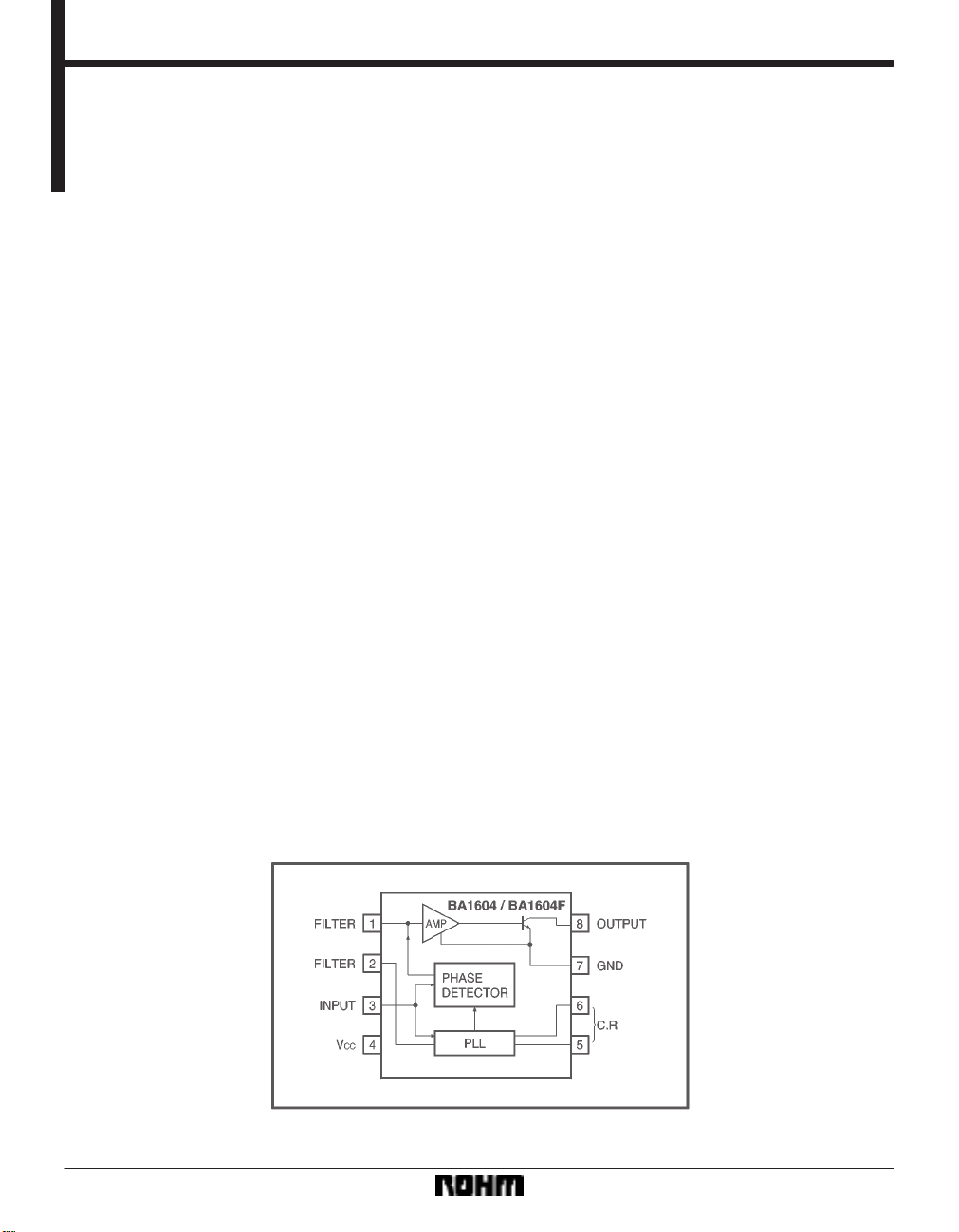
BA1604 / BA1604F
The BA1604 and BA1604F are tone decoder ICs that enable the frequency to be selected in precise detail, using a PLL
system. These ICs are configured of a PLL circuit, a detection circuit, a voltage comparator circuit and an output logic
drive circuit.
When the input signal is within the transmission range of the circuit, PLL is synchronized (locked) to the input signal.
At this point, the output voltage of the decoder drops, and the change turns on the transistors for the voltage comparator
and output logic drive circuits. A load of up to 100mA can be driven.The center frequency (f
the mobile oscillation frequency of the current control oscillator. This frequency is determined by selecting a CR connected to Pins 5 and 6.
Applications
Telephones
Data communication systems
Remote control systems
0) of the decoder is set by
Features
1) The detection bandwidth can be varied independently between 0 and 14%.
2) The output circuit can withstand a load current of up
to 100mA, and is directly coupled to the logic circuit.
3) The center frequency offers a high level of stability.
4) High out-of-band signal and noise rejection capability.
Block diagram
5) Frequency can be changed over a range of 20 : 1 using an external resistor.
6) Compatible with EXAR XR-567 and Signetics
NE567.
212
Communication ICs BA1604 / BA1604F
FAbsolute maximum ratings (Ta=25_C)
FRecommended operating conditions (Ta=25_C)
FElectrical characteristics (unless otherwise noted, Ta=25_C, V
CC=5V)
213

Communication ICs BA1604 / BA1604F
Measurement circuit Application example
Attached components
(1) C
1 and R1 : Setting f0
The center frequency (f0) is determined by the resistor R1
between Pins 5 and 6, and the capacitor C1 between Pin
6 and the ground. The constants at this point are determined as follows :
1
f
0 (kHz) (C : µ F, R : kΩ)
1R1
C
A rectangular-wave voltage is output at Pin 5; the peakto-peak amplitude is between V
erage DC value is V
CC / 2. This pin can drive a load resis-
CC and 1.4 V , and the av-
tance of up to 1kΩ. (The recommended value for R
however, is from 2kΩ to 20kΩ.)
A 1V peak-to-peak exponential function triangular wave
with an average DC voltage level of V
CC / 2 is output at Pin
6. Since loading this pin adversely affects both the duty
cycle and the temperature stability of the oscillator, it
must only be connected to a high-impedance load.
(2) C
2 : Loop filter
Connected between Pin 2 and the ground, C
2 functions
as a low pass filter for the PLL circuit, and the time
constant is determined by T
pedance for Pin 2, at 10 kΩ). The value of C
2 = R2C2 (R2 is the internal im-
2 also deter-
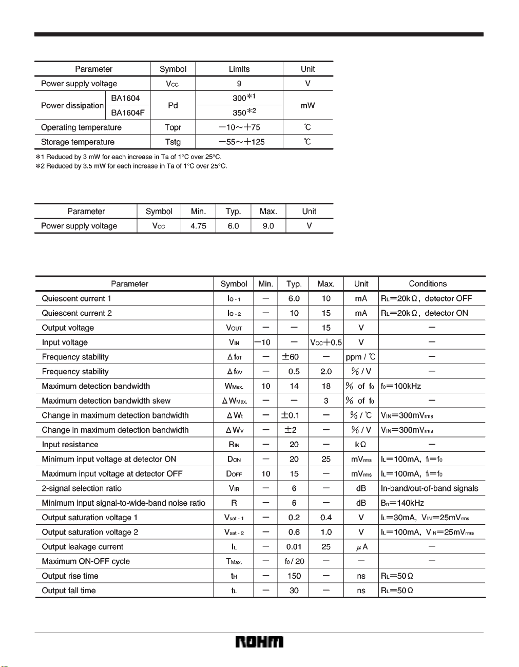
mines the detection bandwidth. The voltage at Pin 2 varies linearly at 20mV / % of f
0.
1.05 f
0 over the range 0.95 f0 to
(3) C
3 : Output filter
Capacitor C
3, connected between Pin 1 and the ground,
is used as a low pass filter to suppress out-of-band signals. The time constant T
3 is determined by T3 = R3C3 (R3
is the internal impedance for Pin 1, at 4.7kΩ).
T o prevent false detection of spurious signals, it is recommended that C
3 2C2. If C3 is made too large, howev-
er, this will increase the time required for voltage changes
at Pin 1 to reach the threshold of the phase detector, thus
slowing the response time.
1,
5 : Power supply filter capacitor
(5) C
4 : Input coupling capacitor
(4) C
Input and output pins
(1) Input : Pin 3
The input signal is applied through a coupling capacitor
to Pin 3. Internal circuits set this pin to a DC potential of
2V with respect to the ground. The input impedance is
approximately 20kΩ.
(2) Output : Pin 8
The output logic section has an internal power transistor
with its collector connected to Pin 8. The load is connected between Pin 8 and V
CC. The transistor saturates
when an in-band input signal is received, dropping the
potential at Pin 8 to less than 1V (0.6V Typ.). The output
can also drive a load connected to a separate supply voltage of up to 20V.
214

Communication ICs BA1604 / BA1604F
Operation notes
When setting the central frequency, which is determined
by the capacitor and resistor connected to pins 5 and 6
of this IC, it is recommended to connect a variable resistor between pins 5 and 6 and align the central frequency
of each component in order to prevent shifting of the central frequency caused by fluctuations in the IC, capacitor,
or resistor.
Electrical characteristic curves
215
Communication ICs BA1604 / BA1604F
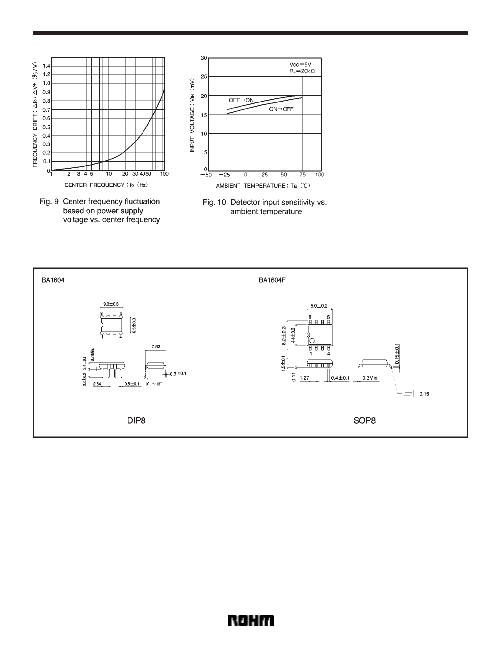
External dimensions (Units: mm)
216
 Loading...