

Page 1
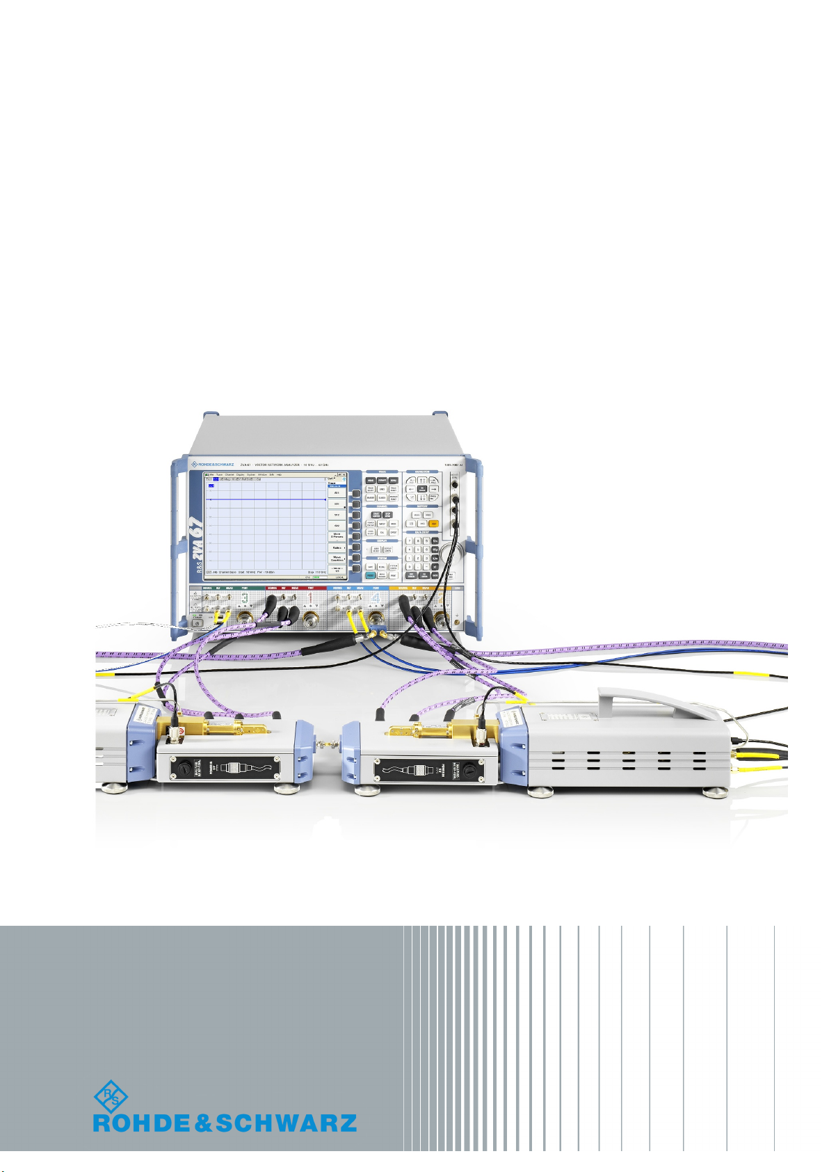
R&S®ZVA110
Broadband Measurements Using the
1 mm External Test Sets
Getting Started
(=>]2Ì)
1314450262
Version 03
Getting Started
Page 2

This Getting Started guide describes the following network analyzer types:
●
R&S® ZVA110 complete system based on R&S®ZVA67
– regular power, stock number 1312.7004.03
– regular power, without RF cables, stock number 1312.7004.05
– high power, stock number 1312.7004.13
– high power, without RF cables, stock number 1312.7004.15
●
R&S® ZVA110 modular system
– regular power, stock number 1312.7004.04
– high power, stock number 1312.7004.14
It complements the Getting Started guide for all R&S®ZVA network analyzers, stock number 1145.1090.62
and the Getting Started guide for frequency converters with electronic attenuators R&S®ZVA-ZxxxE, stock
number 1307.7197.62. It describes the operation of the R&S®ZVA110 with external test sets.
© 2018 Rohde & Schwarz GmbH & Co. KG
Mühldorfstr. 15, 81671 München, Germany
Phone: +49 89 41 29 - 0
Fax: +49 89 41 29 12 164
Email: info@rohde-schwarz.com
Internet: www.rohde-schwarz.com
Subject to change – Data without tolerance limits is not binding.
R&S® is a registered trademark of Rohde & Schwarz GmbH & Co. KG.
Trade names are trademarks of the owners.
1314.4502.62 | Version 03 | R&S®ZVA110
Throughout this document, R&S® is abbreviated as R&S.
Page 3
1
Safety Instructions
Risk of injury and instrument damage
The instrument must be used in an appropriate manner to prevent
electric shock, fire,
●
●
●
●
Keep the "Basic Safety Instructions" and the product documentation
Riesgo de lesiones y daños en el instrumento
El instrumento se debe usar de manera adecuada para p
descargas eléctricas, incendios, lesiones o daños materiales.
●
●
●
especificaciones técnicas pueden contener condiciones adicionales
●
Instrucciones de seguridad
Sicherheitshinweise
Consignes de sécurité
personal injury or instrument damage.
Do not open the instrument casing.
Read and observe the "Basic Sa fety Instructions" delivered as
printed brochure with the instrument.
Read and observe the safety instructions in the following sections.
Note that the data sheet may specify additional operating conditions.
in a safe place and pass them on to the subsequent users.
No abrir la carcasa del instrumento.
Lea y cumpla las "Instrucciones de seguridad elementales"
suministradas con el instrumento como folleto impreso.
Lea y cumpla las instrucciones de seguridad incluidas en las
siguientes secciones. Se debe tener en cuenta que las
para su uso.
Guarde bien las instrucciones de seguridad elementales, así como
la documentación del producto, y entréguelas a usuarios
posteriores.
revenir
1171.1307.42 - 05
Page 4
2
Gefahr von Verletzungen und Schäden am Gerät
Betreiben Sie das Gerät immer ordnungsgemäß, um elektrischen
Schlag, Brand, Verletzungen von Personen oder Geräteschäden zu
verhindern.
●
●
●
●
Risque de blessures et d'endommagement de l'appareil
L'ap
les électrocutions, incendies, dommages corporels et matériels.
●
●
●
suivantes. Il ne faut pas oublier que la fiche technique peut indiquer
●
Öffnen Sie das Gerätegehäuse nicht.
Lesen und beachten Sie die "Grundlegenden Sicherheitshinweise",
die als gedruckte Broschüre dem Gerät beiliegen.
Lesen und beachten Sie die Sicherheitshinweise in den folgenden
Abschnitten; möglicherweise enthält das Datenblatt weitere
Hinweise zu speziellen Betriebsbedingungen.
Bewahren Sie die "Grundlegenden Sicher h ei t s hinweise" und die
Produktdokumentation gut auf und geben Sie diese an weitere
Benutzer des Produkts weiter.
pareil doit être utilisé conformément aux prescriptions afin d'éviter
N'ouvrez pas le boîtier de l'appareil.
Lisez et respectez les "consignes de sécurité fondamentales"
fournies avec l’app ar eil sous forme de brochure imprimée.
Lisez et respectez les instructions de sécurité dans les sections
des conditions d’exploitation supplémentaires.
Gardez les consignes de sécurité fondamentales et la
documentation produit dans un lieu sûr et transmettez ces
documents aux autres utilisateurs.
1171.1307.42 - 05
Page 5

R&S®ZVA110
2.2.1 Test Port Connectors ......................................................................................................8
2.3.1 Test Port........................................................................................................................ 10
2.3.2 H/L SWITCH Connector................................................................................................10
2.3.3 Rear Panel.................................................................................................................... 10
2.3.4 Fuse Holder...................................................................................................................12
Contents
Contents
1 Safety Instructions.................................................................................5
2 Preparing the Analyzer for Use.............................................................7
2.1 Operation with External Test Sets...............................................................................7
2.2 R&S ZVA110 Network Analyzer Connectors...............................................................8
2.3 Diplexer Connectors..................................................................................................... 9
2.4 Frequency Converter Connectors............................................................................. 12
2.4.1 Waveguide Flange........................................................................................................ 12
2.4.2 Rear Panel.................................................................................................................... 12
2.4.2.1 Standby Switch............................................................................................................. 13
2.4.2.2 Power Supply Connector.............................................................................................. 13
2.4.2.3 Fuse Holder...................................................................................................................14
2.4.2.4 RF Connectors – Input.................................................................................................. 14
2.4.2.5 IF Connectors – Output.................................................................................................15
2.4.2.6 Power Control Connector..............................................................................................15
2.5 Putting the Analyzer into Operation.......................................................................... 15
2.5.1 Unpacking and Checking the Instrument...................................................................... 15
2.5.2 Positioning the Instrument.............................................................................................16
2.5.3 Adjusting the Feet of the Test Set................................................................................. 16
2.5.4 Connecting the Control Cable....................................................................................... 17
2.5.5 Connecting the Power Control Cable............................................................................17
2.5.6 Connecting RF Cables.................................................................................................. 17
2.5.7 Connecting the Converter to the DC Supply................................................................. 21
2.5.8 Switching On the External Test Set...............................................................................21
2.5.9 Mounting a DUT............................................................................................................ 22
2.5.10 Replacing Fuses........................................................................................................... 22
2.6 Maintenance................................................................................................................ 22
3Getting Started 1314.4502.62 ─ 03
Page 6

R&S®ZVA110
3.10 Additional Information................................................................................................30
Contents
2.7 Storing and Packing................................................................................................... 22
3 Basic Operation....................................................................................24
3.1 Required Equipment................................................................................................... 24
3.2 Measurement Principle...............................................................................................24
3.3 Activating the ZVA110-BU Measurement Mode........................................................24
3.4 Entering Power Coefficients...................................................................................... 25
3.5 Connecting the External Test Sets............................................................................26
3.6 Power and Frequency Settings..................................................................................27
3.7 Calibration................................................................................................................... 28
3.8 Measurement............................................................................................................... 28
3.9 Troubleshooting..........................................................................................................29
4 Dismounting Frequency Converters.................................................. 31
4.1 Service Re-Calibration................................................................................................32
Index......................................................................................................33
4Getting Started 1314.4502.62 ─ 03
Page 7

R&S®ZVA110
Safety Instructions
1 Safety Instructions
The vector network analyzer R&S ZVA110 has been designed and tested in accordance with the EC Certificate of Conformity. It has left the manufacturer’s plant in a condition fully complying with safety standards.
Risk of instrument damage
To prevent instrument damage, make sure to read through and observe the following
safety instructions.
ESD protective measures
Protect the vector network analyzer and the external test sets against damage due to
electrostatic discharge (ESD). Use the wrist strap and grounding cord supplied with the
analyzer and connect yourself to the GND connector at the front panel of the analyzer.
For details, refer to the R&S ZVA Getting Started guide, stock no. 1145.1090.62.
Input powers RF IN and LO IN
The RF input power at the connectors RF IN and LO IN must not exceed the maximum
values quoted in the data sheet. The maximum values are below the maximum RF
source power of the network analyzer. The "ZVA110-BU" mode ensures compatible
source powers.
Before you connect your external test set to the network analyzer, always activate the
"ZVA110-BU" mode using the "Frequency Converter" dialog (see Chapter 3.3, "Activat-
ing the ZVA110-BU Measurement Mode", on page 24).
Avoid heavy shocks
Heavy shocks can damage inner parts of the devices. Shockproof packing must be
used for storing or dispatching the analyzer and the external test sets.
Opening the instrument
Do not open the frequency converter and diplexer elements of the external test sets. It
can only be repaired at the manufacturer's servicing department.
Using frequency converters separately
The frequency converters can be dismounted from the external test sets and used separately (see Chapter 4, "Dismounting Frequency Converters", on page 31). The
waveguide flanges of the dismounted converters and of the test port adapters must be
protected against mechanical damage. Furthermore, the waveguides must be shielded
from dust.
Protect the waveguide flange of the dismounted converter by leaving a test port
adapter connected. When the converter is not in use, attach one of the included pro-
5Getting Started 1314.4502.62 ─ 03
Page 8

R&S®ZVA110
Safety Instructions
tective caps to the adapter. Avoid scratching the contact surfaces of the waveguide
flanges.
6Getting Started 1314.4502.62 ─ 03
Page 9
R&S®ZVA110
Preparing the Analyzer for Use
Operation with External Test Sets
2 Preparing the Analyzer for Use
The R&S ZVA110 vector network analyzer supports two different measurement modes:
●
Measurements with internal test sets cover a frequency range between 10 MHz
and approx. 67 GHz.
The R&S ZVA110 is based on a four-port R&S ZVA67 vector network analyzer. The
DUT can be connected to any of the four test ports of the R&S ZVA67. One- to
four-port measurements are supported as described in the R&S ZVA Getting Started guide, stock number 1145.1090.62, and in the network analyzer's help system.
●
Measurements with external test sets cover an extended frequency range between
10 MHz and 110 GHz. The DUT is connected to the 1 mm connectors at the front
of the diplexers R&S ZVA-ZD110. This measurement mode is described in the
present manual.
This chapter describes the external test sets and their connection to the DUT and to
the R&S ZVA110 vector network analyzer. A typical measurement example is presented in Chapter 3, "Basic Operation", on page 24.
The measurement mode is selected in the "Frequency Converter" tab of the "System
Configuration" dialog: "<NONE>" for measurements with internal test sets, "ZVA110BU" for external test sets. See Chapter 3.3, "Activating the ZVA110-BU Measurement
Mode", on page 24.
2.1 Operation with External Test Sets
The external test sets enable a frequency range between 10 MHz and 110 GHz. The
analyzer combines two different measurement methods to achieve this extended
range.
●
At frequencies below approx. 67 GHz (i.e. in "low frequency" mode), the frequency
converter in the external test set is bypassed. The source signals of analyzer ports
PORT 1 / 2 are directly fed to the 1 mm test port connectors of the diplexers. The
network analyzer measures the a-waves and b-waves from the REF OUT and
MEAS OUT on the diplexers, respectively. Analyzer ports PORT 3 / 4 and the RF
connectors LO IN, RF IN, REF OUT, and MEAS OUT on the rear panel of the converters are not used.
●
To achieve frequencies above approx. 67 GHz (i.e. to measure in "high frequency"
mode), the frequency converter in the external test set is used. The source signals
of analyzer ports PORT 1 / 2 are fed to the frequency converters, the converted
signals are routed to the 1 mm test port connectors of the diplexers. The frequency
converters use frequency multipliers to transform the source signal into a high-frequency stimulus signal. An additional Local Oscillator (LO) signal from PORT 4 of
the analyzer is used for down-conversion of the reference and measurement channels. A power divider feeds the LO signal to both the left and the right converter.
This test setup ensures a stable phase relationship between both LO signals.
7Getting Started 1314.4502.62 ─ 03
Page 10
R&S®ZVA110
2.2 R&S ZVA110 Network Analyzer Connectors
Preparing the Analyzer for Use
ZVA110 Network Analyzer Connectors
R&S
The analyzer measures the a-waves from REF OUT and the b-waves from MEAS
OUT on the converters. The RF connectors REF OUT, MEAS OUT on the rear
panel of the diplexers are not used.
The network analyzer automatically switches between low frequency and high frequency mode, depending on the stimulus frequency; see Chapter 2.3.2, "H/L SWITCH
Connector", on page 10. There is no need to change the test setup and cabling.
The R&S ZVA110 is based on a four-port R&S ZVA67 vector network analyzer.
The front and rear panel controls and the connectors of the analyzer are described in
the R&S ZVA Getting Started guide, stock number 1145.1090.62 and in the analyzer's
help system. The following sections describe special aspects for measurements with
external test sets.
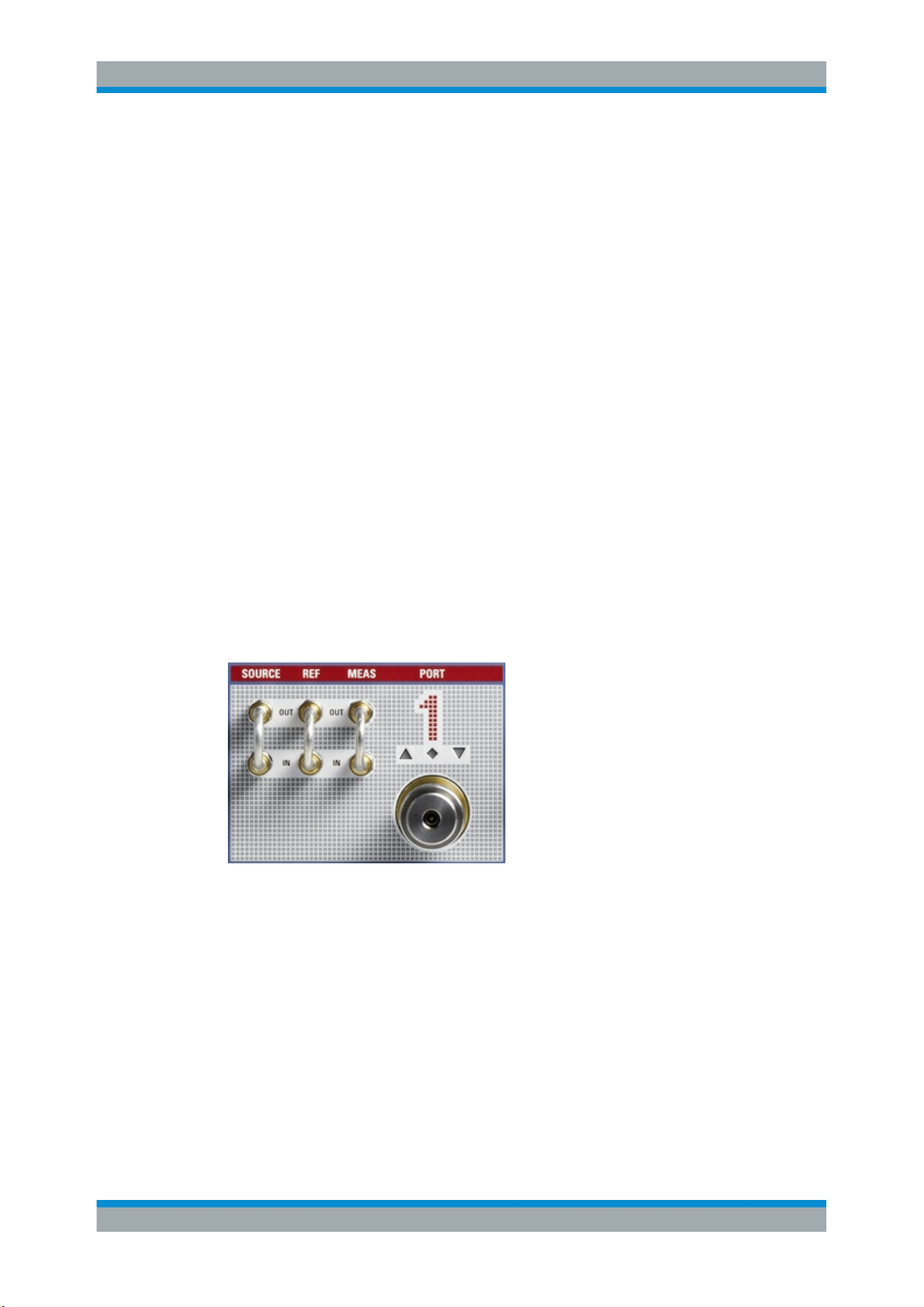
2.2.1 Test Port Connectors
The R&S ZVA67 of the R&S ZVA110 is equipped with four complete test port connector
groups. The PORT 1 to PORT 4 connector groups are similar. Each of them consists of
a bidirectional, ruggedized 1.85 mm connector and 3 pairs of 1.85 mm (V) connectors
for direct generator and receiver access.
The connectors are used alternatively:
●
The ruggedized 1.85 mm connector serves as a test port connector for one- to
four-port measurements with internal test set. In this operating mode, the three
1.85 mm connector pairs are not needed. However, they can provide an extended
measurement functionality (see R&S ZVA Getting Started guide, stock number
1145.1090.62, and the network analyzer's help system). Unused OUT/IN loops
must be jumpered as shown in the figure above.
●
The SOURCE OUT connector provides the RF source signal for the external test
set. SOURCE OUT is connected to the rear panel of the diplexer. In the low frequency range below approx. 67 GHz, REF IN and MEAS IN receive the reference
waves and measured waves from the diplexer, respectively. The 1 mm connector
of the diplexer serves as a test port connector; the ruggedized 1.85 mm connectors
at PORT 1 / 2 are not needed.
8Getting Started 1314.4502.62 ─ 03
Page 11

R&S®ZVA110
2.3 Diplexer Connectors
Preparing the Analyzer for Use
Diplexer Connectors
See also Chapter 2.1, "Operation with External Test Sets", on page 7 and Chap-
ter 2.5.6, "Connecting RF Cables", on page 17.
Maximum input levels
The maximum RF input levels at the ruggedized 1.85 mm connectors, and the
SOURCE, REF, and MEAS inputs (according to the front panel labeling or the data
sheet) must not be exceeded.
Furthermore, it is important that the signals fed in at the SOURCE, REF, and MEAS
inputs contain no DC offset. A DC offset can impair the measurements and even damage the instrument.
The R&S ZVA110 is delivered with two fully assembled external test sets, each consisting of a diplexer R&S ZVA-ZD110 and a frequency converter R&S ZVA-Z110E.
Figure 2-1: Connection between diplexer (right) and frequency converter (left)
The connection of the diplexer and the frequency converter includes conducting lines
for waves and power supply:
●
The RF HIGH OUT connector on the top side of the diplexer is connected to RF IN
on the rear panel of the converter using a semi-rigid RF cable.
●
The waveguide connector on the top side of the diplexer is connected to the waveguide flange of the converter.
●
The connection underneath the waveguide flange ensures the power supply of the
diplexer.
An additional metal clamp at the bottom ensures mechanical stability.
9Getting Started 1314.4502.62 ─ 03
Page 12

R&S®ZVA110
2.3.1 Test Port
Preparing the Analyzer for Use
Diplexer Connectors
Dismounting the frequency converter
The connection shown above is suitable for all operating modes and measurements.
Only dismount the frequency converter from the diplexer if you want to use it separately; see Chapter 4, "Dismounting Frequency Converters", on page 31.
1 mm (m) connector, serves as an output for RF stimulus signals and as an input for
the measured RF signals from the DUT (response signals).
●
With a single external test set, you can generate a stimulus signal and measure the
reflected response signal.
●
With two external test sets, a full 2-port measurement is possible.
Maximum input level, mechanical damage
Do not exceed the maximum input level at the test port according to the data sheet,
especially when using active DUTs or external amplifiers.
To avoid mechanical damage when connecting devices to the 1 mm connector, always
use the torque wrench supplied with the R&S ZVA110.
2.3.2 H/L SWITCH Connector
The H/L SWITCH connectors on the top side of each diplexer are input connectors for
the USER CONTROL signals from the R&S ZVA110 network analyzer unit; see Chap-
ter 2.5.4, "Connecting the Control Cable", on page 17.
2.3.3 Rear Panel
The rear panel of the diplexer provides input and output connectors for RF signals and
a DC input. Connectors labeled LOW are used in low frequency mode only; see Chap-
ter 2.1, "Operation with External Test Sets", on page 7.
Figure 2-2: Rear panel of the diplexer
10Getting Started 1314.4502.62 ─ 03
Page 13

R&S®ZVA110
Preparing the Analyzer for Use
Diplexer Connectors
●
MEAS OUT LOW is a 1.85 mm (V) female connector, which provides the measured
signal (b-wave) in low frequency mode.
●
RF IN LOW / HIGH is a 1.85 mm (V) female connector, which receives the RF
source signal from the R&S ZVA110 network analyzer unit. This connector is used
in low frequency and in high frequency mode.
●
REF OUT LOW is a 1.85 mm (V) female connector, which provides the reference
signal (a-wave) in low frequency mode.
●
The tri-axial FORCE and SENSE connectors and the 4 mm GND socket implement
the bias tee.
Bias is applied via the FORCE input, which is protected by an exchangeable fuse
(see Chapter 2.3.4, "Fuse Holder", on page 12).
The SENSE output is connected to the bias tee via a 1 kΩ resistor, which allows
measuring the bias voltage close to the DUT without the uncertainty caused by a
voltage drop on a long bias line.
MEAS OUT, RF IN, and REF OUT are connected to the corresponding 1.85 mm connectors of PORT 1 / 2 at the R&S ZVA110 network analyzer unit. The complete RF
connection of the external test set is described in Chapter 2.5.6, "Connecting RF
Cables", on page 17.
Maximum input power at RF IN
The RF input power at the RF IN connector must not exceed the maximum value quoted in the data sheet. The maximum value is below the maximum RF source power of
the network analyzer. The "ZVA110-BU" mode ensures compatible source powers.
Before you connect your external test set to the network analyzer, always activate the
"ZVA110-BU" mode using the "Frequency Converter" dialog (see Chapter 3.3, "Activat-
ing the ZVA110-BU Measurement Mode", on page 24).
Maximum input voltage at FORCE and EMI suppression
The maximum nominal input voltage and current for the FORCE bias input connector
must not exceed the value quoted in the data sheet. Use a double-shielded cable and
terminate open cable ends with 50 Ω to ensure successful control of electromagnetic
radiation during operation.
The LED labeled ON lights when the diplexer is properly power-supplied. If the LED
does not light, check the following:
●
The power connection between the diplexer and the converter must be in place
(see Figure 2-1).
●
The converter must be power-supplied and switched on.
●
The fuse at the converter must be intact.
11Getting Started 1314.4502.62 ─ 03
Page 14

R&S®ZVA110
2.3.4 Fuse Holder
2.4 Frequency Converter Connectors
2.4.1 Waveguide Flange
Preparing the Analyzer for Use
Frequency Converter Connectors
A fuse of type IEC 127-F250L at the front protects the diplexer from excess input current at the FORCE connector. A fuse of different type protects the frequency converter
(see Chapter 2.4.2.3, "Fuse Holder", on page 14).
For fuse replacement, refer to Chapter 2.5.10, "Replacing Fuses", on page 22.
The R&S ZVA110 is delivered with two fully assembled external test sets, as described
in Chapter 2.3, "Diplexer Connectors", on page 9. The open connectors of the converter are described in the following sections.
For normal operation, the waveguide adapter with the precision waveguide flange
mounted on top is connected to the diplexer. If the frequency converter is used separately, a DUT can be connected to the waveguide flange. Refer to the Getting Started
guide for frequency converters R&S ZVA-ZxxxE, stock no.1307.7197.62, for detailed
information and safety instructions. This Getting Started guide is available on the
Rohde&Schwarz internet site (see https://www.rohde-schwarz.com/manual/zvaz/).
See also Chapter 4, "Dismounting Frequency Converters", on page 31.
Figure 2-3: Test port adapter of the frequency converter
2.4.2 Rear Panel
The rear panel of the frequency converter provides the connectors and control elements shown below.
12Getting Started 1314.4502.62 ─ 03
Page 15

R&S®ZVA110
Preparing the Analyzer for Use
Frequency Converter Connectors
Figure 2-4: Rear view of the frequency converter
The connectors are described in the following sections.
2.4.2.1 Standby Switch
The standby toggle switch connects (ready state) or disconnects (standby state) the
internal modules of the frequency converter from the power supply. In standby state
also the output connector for the diplexer power supply (see Figure 2-1) is disconnected.
Figure 2-5: Standby switch and LEDs
A green light-emitting diode (LED) next to the switch indicates that the instrument is in
ready state. An orange LED further to the right indicates that the instrument is in
standby state. These LEDs are only lit when the converter is properly connected to the
power supply and the fuse of the instrument is intact.
2.4.2.2 Power Supply Connector
13Getting Started 1314.4502.62 ─ 03
Page 16

R&S®ZVA110
2.4.2.3 Fuse Holder
Preparing the Analyzer for Use
Frequency Converter Connectors
To supply the frequency converter, connect the external DC power supply provided
with the converter to the 9 V / 1.1 A DC input. For details, see Chapter 2.5.7, "Connect-
ing the Converter to the DC Supply", on page 21.
Always switch the instrument to standby state before removing the power supply.
Risk of instrument damage
The input voltage and current must not exceed the maximum values according to the
rear panel labeling or the data sheet.
Always use the DC power supply included in the delivery to power your frequency converter.
A fuse of type IEC60127 T1 L/H protects the frequency converter from excess input
voltages at the power supply connector. A fuse of different type protects the diplexer
(see Chapter 2.3.4, "Fuse Holder", on page 12).
For fuse replacement, see Chapter 2.5.10, "Replacing Fuses", on page 22.
2.4.2.4 RF Connectors – Input
Two 3.5 mm input connectors:
●
RF IN receives the RF source signal from the diplexer. A semi-rigid cable connects
RF IN to the RF HIGH OUT connector on the top side of the diplexer.
●
LO IN receives the local oscillator signal from the R&S ZVA110 network analyzer
unit.
Both input connectors are only used in high frequency mode. The complete RF connection of the external test set is described in Chapter 2.5.6, "Connecting RF Cables",
on page 17.
Risk of instrument damage
The RF input power at the connectors RF IN and LO IN must not exceed the maximum
values quoted in the data sheet. The maximum values are below the maximum RF
source power of the network analyzer. The "ZVA110-BU" mode ensures compatible
source powers.
Before you connect your external test set to the network analyzer, always activate the
"ZVA110-BU" mode using the "Frequency Converter" dialog (see Chapter 3.3, "Activat-
ing the ZVA110-BU Measurement Mode", on page 24).
14Getting Started 1314.4502.62 ─ 03
Page 17

R&S®ZVA110
2.4.2.5 IF Connectors – Output
2.4.2.6 Power Control Connector
Preparing the Analyzer for Use
Putting the Analyzer into Operation
Two SMA output connectors:
●
MEAS OUT provides the measured signal (b-wave) for the R&S ZVA110 network
analyzer unit.
●
REF OUT provides the reference signal (a-wave) for the R&S ZVA110 network
analyzer unit.
The output connectors are connected to the corresponding SMA connectors of PORT
3 / 4 at the R&S ZVA110 network analyzer unit. Both are only used in high frequency
mode. The complete RF connection of the external test set is described in Chap-
ter 2.5.6, "Connecting RF Cables", on page 17.
The three-pin power control connector receives the control signal for the source power
of the vector network analyzer. The control signal is used in the high frequency range
above approx. 67 GHz.
For correct connection read Chapter 2.5.4, "Connecting the Control Cable",
on page 17.
2.5 Putting the Analyzer into Operation
The initial setup of the R&S ZVA110 is described in the R&S ZVA Getting Started
guide, stock number 1145.1090.62 and in the network analyzer's help system. This
section gives additional information related to operation with external test sets.
2.5.1 Unpacking and Checking the Instrument
The R&S ZVA110 network analyzer unit is shipped in a cardboard box; for unpacking
instructions refer to the R&S ZVA Getting Started guide, stock number 1145.1090.62.
Each of the two external test sets is shipped in a separate wooden case. The external
test sets are fully mounted and accompanied by the necessary cables and additional
equipment.
When you receive the shipment, please take the following steps:
1. Unpack the test sets and the other contents of the wooden case.
2. Check the contents of the cases against the list of accessories. Make sure that the
delivery includes all listed items.
3. Remove the protective caps from the 1 mm test ports at the front of the diplexer
elements. Carefully inspect the converters and diplexers. If you notice any damage, immediately notify the shipping company.
15Getting Started 1314.4502.62 ─ 03
Page 18

R&S®ZVA110
2.5.2 Positioning the Instrument
Preparing the Analyzer for Use
Putting the Analyzer into Operation
External test sets returned to Rohde & Schwarz or sent in for repair must be packed in
the original wooden cases. It is also recommended to keep the cases for storing the
test sets and accessories.
See also Chapter 2.7, "Storing and Packing", on page 22 and Chapter 4.1, "Service
Re-Calibration", on page 32.
The R&S ZVA110 is designed for use under laboratory conditions on a bench top. The
surface of the bench top must be flat. The external test sets must be used in horizontal
position.
The general ambient conditions required at the operating site are as follows:
●
The ambient temperature must be in the ranges specified for operation and for
compliance with specifications (see data sheet).
●
All ventilation openings must be unobstructed.
Risk of instrument and DUT damage
To avoid damage of electronic components of the DUT and the R&S ZVA110, the operating site must be protected against electrostatic discharge (ESD).
To prevent ESD damage, use the wrist strap and grounding cord supplied with the network analyzer and connect yourself to the GND connector at the front panel of the analyzer. For details, refer to the R&S ZVA Getting Started guide.
2.5.3 Adjusting the Feet of the Test Set
The frequency converter can be used with three or four feet attached to the bottom
side. If possible, use three feet: two in front and one in the middle of the rear.
Figure 2-6: Setup with one rear foot (left) and two rear feet (right)
16Getting Started 1314.4502.62 ─ 03
Page 19

R&S®ZVA110
2.5.4 Connecting the Control Cable
Preparing the Analyzer for Use
Putting the Analyzer into Operation
Two additional feet support the diplexer. Typically, the external test set can be aligned
as follows:
1. Screw the diplexer feet and the front feet into the instrument as far as possible.
2. Use the rear foot to align the entire test set parallel to the surface of the bench top.
3. When you connect a DUT in-between two test sets (see Chapter 2.5.9, "Mounting
a DUT", on page 22), use the diplexer feet for further alignment.
Switchover between low frequency and high frequency mode is automatically controlled from the R&S ZVA110 network analyzer unit. Use the "H/L Switch" cable to connect
the USER CONTROL connector on the rear panel of the analyzer to the H/L SWITCH
connectors on the top side of the diplexers.
The "H/L Switch" cable is supplied with the R&S ZVA110. The cable end labeled H/L
SWITCH PORT 1 is intended for the "left" diplexer (connected to the analyzer ports 1
and 3). The cable end labeled H/L SWITCH PORT 2 is for the "right" diplexer (connected to ports 2 and 4).
The H/L switch mechanism is controlled by the drive port bits no. 1 and 2 (pins no. 16
and 17) of the USER CONTROL connector. For a detailed description of the connector,
refer to the help system of your network analyzer.
Low frequency mode
In low frequency mode, the control cable is not needed – even if the DUT is connected
to the 1 mm test port connectors of the diplexers. Remove the control cable, if no frequencies above approx. 67 GHz are measured.
2.5.5 Connecting the Power Control Cable
The source power of the vector network analyzer is controlled from the R&S ZVA67
vector network analyzer. Connect the 3-pin control connector at the rear panel of the
converter to the output connector of option R&S ZVA-B8 (EXTATT CTRL) at the top
right of the R&S ZVA front panel. A suitable control cable is supplied with each converter.
The numbers below the EXTATT CTRL connectors denote the controlled analyzer
ports. Control connector numbers and analyzer port numbers must always be the
same.
2.5.6 Connecting RF Cables
The R&S ZVA110 is delivered with two fully assembled external test sets, each consisting of a diplexer R&S ZVA-ZD110 and a frequency converter WR10 R&S ZVA-Z110E.
17Getting Started 1314.4502.62 ─ 03
Page 20

R&S®ZVA110
Preparing the Analyzer for Use
Putting the Analyzer into Operation
The "internal" connection between the diplexers and frequency converters is described
in Chapter 2.3, "Diplexer Connectors", on page 9. The left test set is intended for
PORT 1 / PORT 3 of the R&S ZVA67 network analyzer; the right test set for PORT 2 /
PORT 4. Connection of the two test sets is analogous.
Risk of instrument damage
The RF input power at the RF IN and LO IN connectors must not exceed the maximum
value quoted in the data sheet. The maximum value is below the maximum RF source
power of the network analyzer. The "ZVA110-BU" mode ensures compatible source
powers.
Before you connect your external test set to the network analyzer, always activate the
"ZVA110-BU" mode using the "Frequency Converter" dialog (see Chapter 3.3, "Activat-
ing the ZVA110-BU Measurement Mode", on page 24).
Connecting cables, risk of damage
A full set of connecting cables including the necessary adapters (for instrument types
03 and 04) is supplied with the R&S ZVA110. It is strictly recommended to use these
high-quality cables for the RF connection. For accurate measurement results, RF
cables must have a low attenuation and an excellent phase stability.
Tightening the cable connectors too much can cause damage. Loose connections can
result in inaccurate measurement results. For these reasons always use appropriate
torque wrenches, suitable for the different connectors types. A torque wrench for the
delicate 1 mm connector is supplied with the R&S ZVA110.
Some of the RF connections are only used while the network analyzer operates in the
low frequency range (below approx. 67 GHz) or in the high frequency range (above
approx. 67 GHz). However, to ensure full flexibility and maximum accuracy, it is recommended to establish all RF connections.
1. Ensure that the converter is in standby state or disconnected from the power supply (see Chapter 2.4.2.1, "Standby Switch", on page 13).
2. Make sure the "ZVA110-BU" mode is active (see Chapter 3, "Basic Operation",
on page 24).
3. Connect the RF input and output connectors of the diplexers and the frequency
converters as shown below.
The following figure shows the cabling of the left test set to the R&S ZVA67 network
analyzer. Notice that the test port connector PORT 4 provides the LO IN signal for both
the left and the right converters. An appropriate RF power divider R&S ZV-Z1227 is
supplied with the R&S ZVA110.
18Getting Started 1314.4502.62 ─ 03
Page 21

R&S®ZVA110
Preparing the Analyzer for Use
Putting the Analyzer into Operation
Figure 2-7: Connection of left test set
Table 2-1: RF connection for left external test set
R&S ZVA67 connector Ext. test set connector Cable Used at frequencies
PORT 1 – SOURCE OUT Diplexer – RF IN R&S ZV-Z196 67 GHz, 1.85 mm (M) –
1.85 mm (M), 0.6 m
PORT 1 – REF IN Diplexer – REF OUT R&S ZV-Z196 67 GHz, 1.85 mm (M) –
1.85 mm (M), 0.6 m
PORT 1 – MEAS IN Diplexer – MEAS OUT R&S ZV-Z196 67GHz, 1.85 mm (M) –
1.85 mm (M), 0.6 m
PORT 3 – SOURCE OUT
must be connected to
PORT 3 – SOURCE IN
PORT 3 – REF IN Converter – REF OUT CABLE MEAS, 1.55 m HIGH
PORT 3 – MEAS IN Converter – MEAS OUT CABLE REF, 1.55 m HIGH
– – –
1)
LOW / HIGH
LOW
LOW
1) The output signal at the ruggedized test port PORT 3 can be used as an auxiliary
signal, e.g. an LO signal for a mixer under test.
Table 2-2: RF connection for right external test set
R&S ZVA67 connector Ext. test set connector Cable Used at frequencies
PORT 2 – SOURCE OUT Diplexer – RF IN R&S ZV-Z196, 1.85 mm (M) – 1.85 mm (M),
0.6 m
PORT 2 – REF IN Diplexer – REF OUT R&S ZV-Z196, 1.85 mm (M) – 1.85 mm (M),
0.6 m
PORT 2 – MEAS IN Diplexer – MEAS OUT R&S ZV-Z196, 1.85 mm (M) – 1.85 mm (M),
0.6 m
LOW / HIGH
LOW
LOW
19Getting Started 1314.4502.62 ─ 03
Page 22

R&S®ZVA110
Preparing the Analyzer for Use
Putting the Analyzer into Operation
R&S ZVA67 connector Ext. test set connector Cable Used at frequencies
PORT 4 – ruggedized connector
PORT 3 – SOURCE OUT
must be connected to
PORT 3 – SOURCE IN
PORT 4 – REF IN Converter – REF OUT CABLE MEAS, 1.55 m HIGH
PORT 4 – MEAS IN Converter – MEAS OUT CABLE REF, 1.55 m HIGH
Power divider to both converter – LO IN connectors
– – –
R&S ZV-Z193, 3.5 mm (M) – 3.5 mm (M),
1.5 m
R&S ZV-Z1227, POWER DIVIDER
HIGH
Figure 2-8: Complete test setup for 2-port transmission measurement
Right and left diplexers and converters
A label on the rear panel of the network analyzer shows the two diplexer and converter
units with their position. The label contains the following information.
20Getting Started 1314.4502.62 ─ 03
Page 23

R&S®ZVA110
Preparing the Analyzer for Use
Putting the Analyzer into Operation
Figure 2-9: System component information
Compliance with rated specifications
The "left" external test set (consisting of one diplexer R&S ZVA-ZD110 plus one converter R&S ZVA-Z110E) is connected to analyzer ports 1 and 3. The "right" external
test set is connected to analyzer ports 2 and 4. Compliance with the rated specifications requires a system setup according to the rear panel labeling. Never interchange
the left and right diplexer and converter units, and never interchange diplexers and
converters from different R&S ZVA110 systems.
2.5.7 Connecting the Converter to the DC Supply
An external DC power supply and several plug adapters are provided with each of the
external test sets. Select the appropriate adapter and attach it to the power supply. To
remove a mounted adapter, press the small button next to the adapter and push the
adapter away from the button.
Connect the power supply to the 9 V / 1.1 A DC input at the rear panel of the frequency
converter (see Chapter 2.4.2.2, " Power Supply Connector", on page 13) and to a
power outlet. The power supply supports input AC voltages between 100 V and 240 V
and frequencies between 47 Hz and 63 Hz.
A lit LED next to the standby switch indicates that the power supply operates appropriately. If neither of the two LEDs is lit, check the fuse of the instrument (see Chap-
ter 2.5.10, "Replacing Fuses", on page 22).
2.5.8 Switching On the External Test Set
The standby toggle switch is located at the rear panel (see Chapter 2.4.2.1, "Standby
Switch", on page 13). To switch the external test set to ready state, press the key. The
green LED next to the switch must be lit now.
21Getting Started 1314.4502.62 ─ 03
Page 24

R&S®ZVA110
2.5.9 Mounting a DUT
2.5.10 Replacing Fuses
Preparing the Analyzer for Use
Storing and Packing
After switching the external test set to the ready state, a warm-up time of one hour is
required to ensure accurate measurements. The instrument is only warmed-up in
ready state, not in standby state.
The DUT must be screwed to the 1 mm test port connector at the front of the diplexer.
A tight connection is essential to ensure precise calibration and measurement results.
Depending on the connectors of the DUT, possibly additional adapters are required.
For two-port measurements, two external test sets must be connected to one DUT.
Use the adjustable feet of the test sets to align the DUT accurately.
The frequency converter is protected by a fuse of type IEC60127 T1 L/H, the diplexer
by a fuse of type IEC127-F250L. To replace a fuse, open the fuse holder by slightly
turning the lid counter-clockwise, preferably using a small coin. Replacement fuses are
provided with the instrument.
2.6 Maintenance
The external test sets do not require any special maintenance. Make sure that the air
vents of the frequency converters are not obstructed. The outside can be cleaned
using a soft, line-free dust cloth.
Risk of damage
Cleaning agents contain substances that can damage the external test set, e.g. the
front panel labeling or plastic parts.
Never use cleaning agents such as solvents (thinners, acetone etc.), acids, bases or
other substances.
For our support center address and a list of useful R&S contact addresses, refer to the
pages at the beginning of this guide.
2.7 Storing and Packing
The R&S ZVA110 network analyzer unit and the external test sets can be stored in the
temperature range quoted in the data sheet. When stored for a longer period of time,
the devices must be protected against dust.
22Getting Started 1314.4502.62 ─ 03
Page 25

R&S®ZVA110
Preparing the Analyzer for Use
Storing and Packing
Transport and store the external test sets in their original wooden cases. The 1 mm
test port of the diplexer must be protected by its cap; see also Chapter 2.5.1, "Unpack-
ing and Checking the Instrument", on page 15.
The waveguide flanges of dismounted frequency converters must be protected against
mechanical damage and shielded from dust; see Chapter 4, "Dismounting Frequency
Converters", on page 31.
23Getting Started 1314.4502.62 ─ 03
Page 26

R&S®ZVA110
3.1 Required Equipment
3.2 Measurement Principle
Basic Operation
Activating the ZVA110-BU Measurement Mode
3 Basic Operation
This chapter describes the use of an R&S ZVA110 vector network analyzer with two
external test sets for 2-port transmission measurements.
One-port reflection measurements can be performed in a similar way using a single
external test set.
The R&S ZVA110 system is delivered with all measurement equipment needed. An
additional 1 mm calibration kit is required for system error correction (calibration).
The principle of the measurement with external test sets is described at the beginning
of this guide; refer to Chapter 2.1, "Operation with External Test Sets", on page 7.
The measurement involves the following steps:
1. Activation of the "ZVA110-BU" mode for measurements with external test set
2. Entry of power coefficients (when using an external test set for the first time).
3. Connection of the external test sets
4. Power and frequency settings
5. Power calibration using an appropriate external power meter
6. System error correction (calibration) using a suitable calibration kit
7. Connection of the DUT and measurement
3.3 Activating the ZVA110-BU Measurement Mode
After a factory preset, the R&S ZVA67 is configured for measurements using the internal test sets. Activate the "ZVA110-BU" mode explicitly before you connect the external
test sets.
To activate the "ZVA110-BU" mode:
1. Click "System" > "System Config ..." to open the "System Configuration" dialog.
2. Activate the "Frequency Converter" tab.
3. Select "Type" : "ZVA110-BU".
24Getting Started 1314.4502.62 ─ 03
Page 27

R&S®ZVA110
Basic Operation
Entering Power Coefficients
4. Click "Apply" to activate the mode.
5. If you use your vector network analyzer for the first time, click "Coefficients" to
enter the power coefficients; see Chapter 3.4, "Entering Power Coefficients",
on page 25.
6. "Close" the "System Configuration" dialog.
Analyzer settings with active "ZVA110-BU" mode
In "ZVA110-BU" mode, the frequency and level settings of the network analyzer are
automatically set to be compatible with the external test sets. "Low Phase Noise" is
enabled, Automatic Level Control (ALC) is disabled. The frequency and levels of all
ports are displayed in the "Port Configuration" dialog ("Channel" > "Mode" > "Port Config …").
Figure 3-1: Frequency Converter dialog
3.4 Entering Power Coefficients
For accurate control of the converter output power, the R&S ZVA67 analyzer must
know the (non-linear) current-power characteristic of the frequency converters. The
characteristic is sufficiently described by a third-order polynomial. A label with the four
polynomial coefficients c0, c1, c2, and c3 is affixed to each converter.
25Getting Started 1314.4502.62 ─ 03
Page 28

R&S®ZVA110
Basic Operation
Connecting the External Test Sets
When the R&S ZVA110 is used for the first time, it is recommended to check whether
the power coefficients on the converter labels correspond to the entries in the analyzer
dialog. Proceed as follows:
1. Activate the "ZVA110-BU" mode following the first steps in Chapter 3.3, "Activating
the ZVA110-BU Measurement Mode", on page 24.
2. In the "Frequency Converter" dialog, press "Coefficients".
3. In the "Power Coefficients" dialog opened, clear "Use default coefficients". Adjust
the coefficients in the dialog to the converter coefficients, if necessary.
The numbers of the table rows in the dialog denote the analyzer ports for the converters.
4. Repeat the last step for both frequency converters/external test sets.
3.5
Figure 3-2: Entry of power coefficients for analyzer port 1
Connecting the External Test Sets
Each of the external test sets must be connected to the R&S ZVA110 base unit, the
power supply and the DUT. Please refer to the following sections for details.
●
Power control connection: See Chapter 2.5.5, "Connecting the Power Control
Cable", on page 17
●
H/L SWITCH (control connection): Chapter 2.5.4, "Connecting the Control Cable",
on page 17
●
RF connection: See Chapter 2.5.6, "Connecting RF Cables", on page 17
●
Power supply: See Chapter 2.5.7, "Connecting the Converter to the DC Supply",
on page 21
●
DUT (usually connected after calibration): See Chapter 2.5.9, "Mounting a DUT",
on page 22
26Getting Started 1314.4502.62 ─ 03
Page 29

R&S®ZVA110
3.6 Power and Frequency Settings
Basic Operation
Power and Frequency Settings
While the "ZVA110-BU" mode is active, the "Channel" > "Stimulus" settings of the network analyzer control the frequency and power range of the converters. The "Channel"
> "Mode " > "Port Configuration" dialog shows an additional row for each converter.
The "Power" and "Frequency" settings in the "Source" section of the dialog serve different purposes:
●
The "Power" setting defines the output power for each external test set. After a
source power calibration of the converter ports, the analyzer will generate the
selected source powers at the 1 mm test port connectors of the external test sets;
see Chapter 3.7, "Calibration", on page 28.
Port 4 provides the local oscillator signal for the converters. The default source
power setting ensures a suitable input level of approx. 7 dBm at the LO IN connectors.
●
The source frequencies at the 1 mm test ports are determined by the port frequencies of the analyzer: The "Port 1" and "Port 2" source frequencies define the source
frequencies of the left and right external test sets, respectively.
The "Converter Port 1" and "Converter Port 2" frequency settings in the "Port Configuration" dialog define the frequency axes for the source power calibrations. They
do not affect the source frequencies at the 1 mm test ports. For best accuracy,
ensure that the correct converter frequencies are set, especially if the test setup
contains additional frequency-converting components.
Example:
In the example below, the frequency at the NWA "Port 1" has been increased by a 1
GHz offset. The same offset has been entered for "Converter Port 1". This setting
ensures a correct frequency axis during the power calibration.
Figure 3-3: Converter frequency and power settings
27Getting Started 1314.4502.62 ─ 03
Page 30

R&S®ZVA110
3.7 Calibration
Basic Operation
Measurement
A source power calibration for an external test set requires an appropriate external
power meter, to be connected to the converter's 1 mm test port connector. The power
meter is configured in the ordinary way using the "System Configuration" > "External
Power Meters" tab.
To perform the source power calibration, proceed as follows:
1. Connect the power meter and open the "Channel" > "Calibration" > "Start Power
Cal" > "Source Power Cal" dialog.
2. Select the converter source port to calibrate from the "Source" pull-down list (e.g.
"Port 1" for the left external test set connected to Port 1 and Port 3).
3. Click "Modify Settings" and ensure that both "Flatness Cal" and "Reference
Receiver Cal" are checked.
4. If your test setup causes strong nonlinear effects, you can choose a "Convergence
Factor" different from one.
5. Start the calibration sweep.
To ensure an accurate source power calibration and quick convergence, use the correct power coefficients; see Chapter 3.7, "Calibration", on page 28.
A receiver power calibration of the b-waves (without external power meter, using the
“Receiver Power Calibration” dialog) is possible after completed source power calibration.
After the power calibration procedure, a system error correction is recommended. Measurements with external test sets require a 1 mm calibration kit for system error correction.
3.8 Measurement
After power calibration and system error correction, the millimeter wave measurement
can be performed like any other network analyzer measurement. The analyzer can
perform frequency and power sweeps. The "Port Configuration" settings (together with
the "Stimulus" settings), determine the sweep range of the converted signals (for a frequency sweep, the input and output frequencies at the DUT ports). All measured quantities (S-parameters, wave quantities, ratios etc.) and other trace settings are available.
The following example shows a transmission measurement on a through connection in
the frequency range between 10 MHz and 110 GHz.
28Getting Started 1314.4502.62 ─ 03
Page 31

R&S®ZVA110
Basic Operation
Troubleshooting
Figure 3-4: Transmission measurement with an R&S ZVA110
For best measurement accuracy, observe the following rules:
●
Enter the correct power coefficients of all frequency converters; see Chapter 3.4,
"Entering Power Coefficients", on page 25.
●
Perform a source power calibration; see Chapter 3.7, "Calibration", on page 28.
Using output powers at the 1 mm connectors outside the calibrated range generally
impairs the measurement accuracy. The effect is enhanced if the power coefficients are not correct.
●
Perform a system error correction for the power-calibrated test setup using an
appropriate calibration kit.
3.9 Troubleshooting
The table below lists possible errors and remedies.
29Getting Started 1314.4502.62 ─ 03
Page 32

R&S®ZVA110
Error Possible cause Remedy
Basic Operation
Additional Information
No output signal, LED next to the mains
switch on the rear of the converter panel
off.
Switchover between low frequency and
high frequency mode fails
Inconclusive measurement results REF and MEAS cables at the diplexer or
Measurement shows noise only No supply power at the diplexer unit See Chapter 2.3, "Diplexer Connectors",
Power control fails, external test sets
operate at maximum output power.
Inaccurate source levels at the 1 mm
ports
Inaccurate source levels, even at reduced
speed
Converter not power-supplied Check power supply and fuse (see Chap-
ter 2.5.8, "Switching On the External Test
Set", on page 21).
Control connection not established or Port
1 and Port 2 connectors interchanged
at the converter are interchanged
Power control connection not established Check connecting cables and port assign-
Insufficient settling time, especially for fast
sweep and strong power variations
Power coefficients entered and converters
do not match, e.g. the coefficients of port
1 and port 2 are interchanged
Check connecting "H/L Switch" cable (see
Chapter 2.5.4, "Connecting the Control
Cable", on page 17).
See Figure 2-7.
on page 9.
ment of control connectors.
Increase sweep time ("Channel" >
"Sweep " > "Sweep Time").
Make sure that all coefficients are correct
and assigned to the right analyzer ports
(see Chapter 3.4, "Entering Power Coeffi-
cients", on page 25).
3.10 Additional Information
For a comprehensive description of R&S ZVA analyzers, including frequency conversion and remote control, refer to the R&S ZVA help system or to the printable operating
manual. The latter is available for download at http://www.rohde-schwarz.com/product/
zva.
Application notes related to frequency converters are also available for download, see
http://www.rohde-schwarz.com/application/zvaz.
The text book "Fundamentals of Vector Network Analysis" by Michael Hiebel is an ideal
complement for the information given in the user documentation. The book combines
theoretical background and practical measurements on R&S ZVA network analyzers. If
you are interested, please contact your local R&S office.
30Getting Started 1314.4502.62 ─ 03
Page 33

R&S®ZVA110
Dismounting Frequency Converters
4 Dismounting Frequency Converters
The frequency converters can be dismounted from the external test sets and used separately. They can be used in combination with any network analyzer R&S ZVA with an
upper frequency limit of 20 GHz or higher (R&S ZVA24, R&S ZVA40 ...). Option
R&S ZVA-B8 is required to establish the power control connection between the analyzer and the converters.
The frequency converters provide:
●
A frequency range between 75 GHz and 110 GHz
●
Direct connection of DUTs with waveguide flanges
●
System error correction using waveguide calibration kits (e.g. R&S ZV-WR10)
For detailed information about measurements with external frequency converters, refer
to the Getting Started guide R&S ZVA-Z90E / -Z110E, and to your network analyzer's
operating manual (see https://www.rohde-schwarz.com/manual/zvaz/).
Dismounting the converter
To detach the frequency converter from the diplexer:
1. Unscrew the semi-rigid RF cable between the RF HIGH OUT connector on the top
side of the diplexer and the RF IN connector on the rear panel of the converter.
2. Turn the external test set by 90° so that the diplexer connectors point in upward
direction.
3. Open the corrugated union screw of the power supply cable between the converter
and the diplexer manually, leaving the cable attached to the diplexer.
4. Open two screws at the U-shaped metal clamp, leaving the clamp attached to
either the converter or the diplexer.
5. Put the external test set back on its feet.
6. Use the hexball driver supplied with the R&S ZVA110 to open all screws at the
waveguide flange, leaving the adapter attached to the converter.
7. Carefully detach the two devices in horizontal direction.
Risk of damaging waveguide flanges
The waveguide flanges of the dismounted converter and of the test port adapters must
be protected against mechanical damage. Furthermore, the waveguides must be shielded from dust.
Protect the waveguide flange of the dismounted converter by leaving a test port
adapter connected. When the converter is not in use, attach one of the included protective caps to the adapter. Avoid scratching the contact surfaces of the waveguide
flanges.
31Getting Started 1314.4502.62 ─ 03
Page 34

R&S®ZVA110
4.1 Service Re-Calibration
Dismounting Frequency Converters
Service Re-Calibration
Remounting the converter
To remount the converter, perform the steps described above in reverse order. Use a
torque wrench to tighten the semi-rigid RF cable to the SMA connectors and notice that
the RF cables of the left and right test sets are not identical.
For accurate measurements, the R&S ZVA110 must be recalibrated by Rohde &
Schwarz after the calibration interval in the data sheet has elapsed. Calibration
involves all components of the test system, including the R&S ZVA67 network analyzer
and both external test sets.
To help us carry out your order as quickly as possible, please always return the complete test system. Observe the label on the rear panel of the network analyzer to
ensure that all components belong together.
32Getting Started 1314.4502.62 ─ 03
Page 35

R&S®ZVA110
Index
Index
B
Basic operation ................................................................. 24
C
Calibration ......................................................................... 28
Control connector .............................................................. 15
D
DC bias
FORCE ....................................................................... 10
GND ............................................................................ 10
SENSE ........................................................................ 10
DC power .......................................................................... 21
Diplexer ............................................................................... 9
Dismounting converters .................................................... 31
DUT ................................................................................... 22
F
Feet ................................................................................... 16
FORCE (DC bias) ............................................................. 10
Frequency converter
Dismount ..................................................................... 31
Mount .......................................................................... 31
Standalone operation .................................................. 31
Frequency settings ............................................................ 27
Fuse
diplexer ....................................................................... 12
frequency converter .................................................... 14
replacement ................................................................ 22
G
GND (DC bias) .................................................................. 10
H
H/L SWITCH ..................................................................... 10
H/L Switch cable ............................................................... 17
I
IF connector outputs ......................................................... 15
Input powers ...................................................................... 14
Instrument setup ............................................................... 16
L
Power calibration ............................................................... 28
Power Coefficients ............................................................ 25
Power control cable ........................................................... 17
Power on ........................................................................... 21
Power settings ................................................................... 27
Power supply connector .................................................... 13
Preparing the analyzer for use ............................................ 7
R
Rear panel
diplexer ....................................................................... 10
frequency converter .................................................... 12
REF OUT .......................................................................... 15
REF OUT LOW ................................................................. 10
Replacing fuses ................................................................. 22
Required Equipment ......................................................... 24
RF connection ................................................................... 17
RF connector inputs .......................................................... 14
RF IN ................................................................................. 14
RF IN LOW / HIGH ............................................................ 10
S
SENSE (DC bias) .............................................................. 10
Service recalibration .......................................................... 32
Standby switch .................................................................. 13
Storing the instrument ....................................................... 22
System Configuration ........................................................ 24
System error correction ..................................................... 28
T
Test port
analyzer ........................................................................ 8
diplexer ....................................................................... 10
Troubleshooting ................................................................. 29
U
Unpacking ......................................................................... 15
W
Waveguide flange .............................................................. 12
Z
ZVA110-BU (measurement mode) .................................... 24
LO IN ................................................................................. 14
M
Maintenance ...................................................................... 22
MEAS OUT ....................................................................... 15
MEAS OUT LOW .............................................................. 10
Measurement .................................................................... 28
Measurement principle ...................................................... 24
P
PORT 1 / 2 / 3 / 4 ................................................................ 8
Port Configuration ............................................................. 27
33Getting Started 1314.4502.62 ─ 03
 Loading...