

Page 1
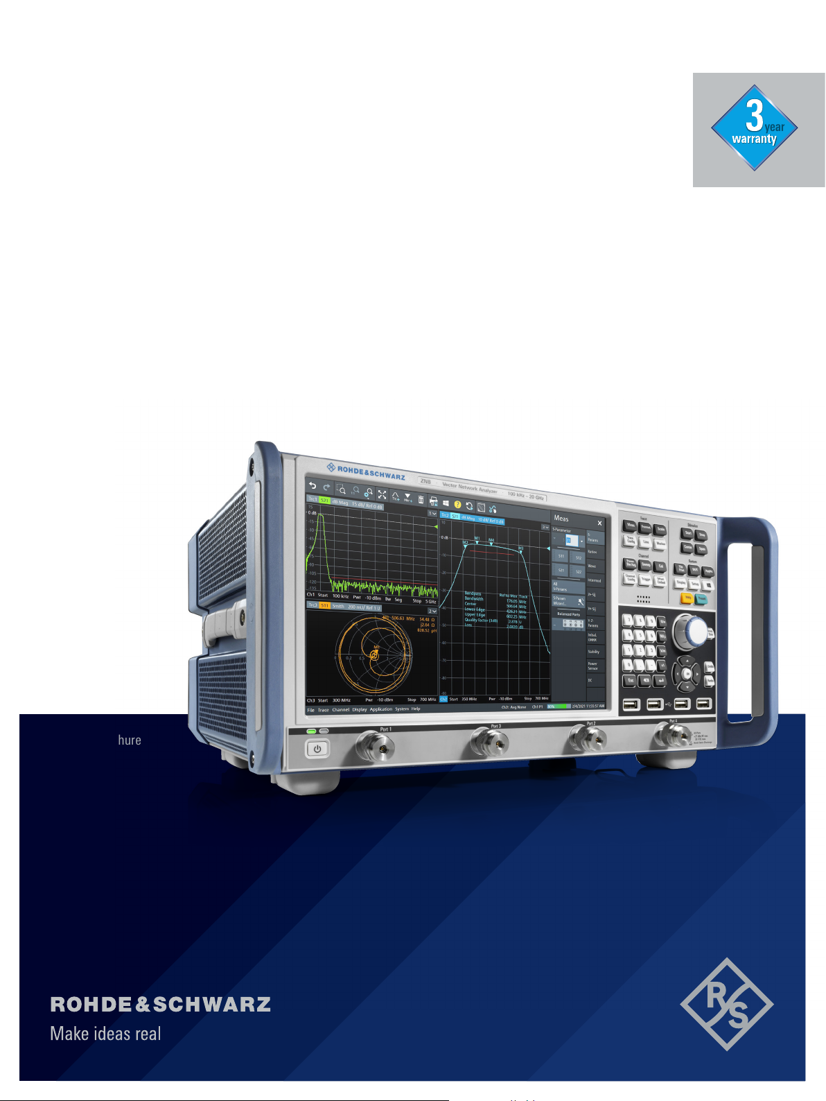
R&S®ZNB
VECTOR NETWORK ANALYZER
Leading in speed, dynamic range
and ease of operation
year
Product Brochure
Version 01.00
Page 2
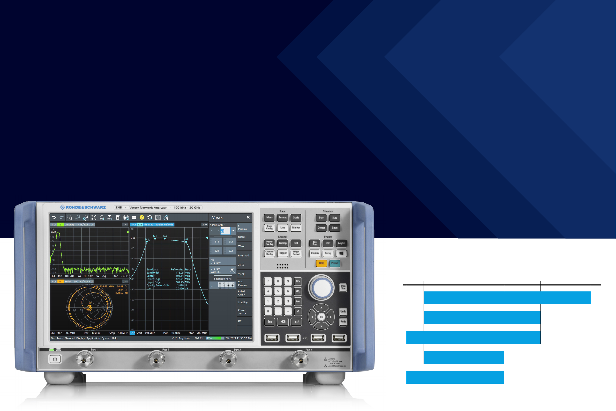
AT A GLANCE BENEFITS KEY FACTS
More than 60 years of experience in the field of vector network analysis pay off: Rohde & Schwarz sets
new benchmarks with its R&S®ZNB family of vector network analyzers. These analyzers feature high
measurement speed, outstanding precision and exceptional ease of operation.
With frequency ranges of 9kHz to 4.5GHz/8.5GHz and
100kHz to 20GHz, the network analyzers are targeted
at applications in the mobile radio, electronic goods and
aerospace and defense sectors, plus they can be used in
high speed printed board design. The R&S®ZNB is the right
choice when it comes to developing, producing and servicing RF components such as amplifiers, mixers, filters,
connectors and cables.
The R&S®ZNB vector network analyzers feature a wide
dynamic range of up to 140dB (at 10Hz IF bandwidth),
low trace noise of less than 0.004dB RMS (at 10kHz IF
bandwidth) and high output power of up to +13dBm,
which can be adjusted electronically in a range of more
than 98dB.
The R&S®ZNB analyzers combine high measurement accuracy with exceptional speed – better than 5µs per point.
They feature excellent temperature and long-term stability,
which ensures reliable measurements over several days
without having to recalibrate the units.
The short-depth, compact 2-port and 4-port analyzers
leave plenty of space on the workbench for the measurement application. They feature low operating noise thanks
to low power consumption and a sophisticated cooling
concept. Low power consumption also reduces operating
costs and protects the environment.
► Frequency range from 9kHz up to 20GHz
► Wide dynamic range of up to 140dB
► Short sweep times, e.g. 4ms for 401points
► High temperature stability of typ. 0.014dB/K
► Wide power sweep range of 98dB
► Wide range of IF bandwidths from 1Hz to 10MHz
► Manual and automatic calibration
► Large, high-resolution 12.1" screen
► Touchscreen user interface
► 2 or 4 ports
► 4-port model with two independent internal
sources
► Expansion to up to 48 ports using switch matrices
Designed to meet the highest standards
►
page 4
Convenient characterization of active and passive
RFcomponents
►
page 6
Simple calibration– manualorautomatic
►
page 9
Network analysis made easy
►
page 10
High throughput inproduction
►
page 12
Measurements on up to 48ports
►
page 14
A worthwhile investment
►
page 16
R&S®ZNB models
9 kHz
Rohde & Schwarz R&S®ZNB Vector Network Analyzer 32
100 kHz
R&S®ZNB20 vector network analyzer
2-port and 4-port, without bias tee
R&S®ZNB8 vector network analyzer
2-port and 4-port, with bias tee
R&S®ZNB8 vector network analyzer
2-port and 4-port, without bias tee
R&S®ZNB4 vector network analyzer
2-port and 4-port, with bias tee
R&S®ZNB4 vector network analyzer
2-port and 4-port, without bias tee
4.5 GHz
8.5 GHz
20 GHz
Page 3

DESIGNED TO MEET THE HIGHEST
STANDARDS
The analyzers of the R&S®ZNB family combine wide dynamic range, excellent raw data, high temperature
stability and fast synthesizers to yield performance previously found only in high-end network analyzers.
This makes the instruments ideally suited for applications in the development and large-scale production of
sophisticated RF components.
Wide dynamic range starting from 9kHz for fast
measurements on high-blocking DUTs
The R&S®ZNB receivers combine high power-handling
capacity with high sensitivity and low trace noise. The
R&S®ZNB base unit provides typically 140dB dynamic
range (at10Hz IF bandwidth), which is better than that of
other, comparable products on the market.
The R&S®ZNB4-B52/-B54 and R&S®ZNB8-B52/-B54
options further extend the dynamic range, delivering a
value as high as 150dB for measure ments between ports
(real dynamic range, i.e.without receivers going into compression at low transmission coefficients). This mainly
speeds up manual adjustments on high-blocking filters.
Users will benefit from the wide dynamic range of the
R&S®ZNB not only in the mobile radio frequency bands,
but right from the 9kHz start frequency.
R&S®ZNB dynamic range (at 10Hz IF bandwidth).
Excellent raw data for high basic accuracy
The R&S®ZNB offers directivity of more than 30dB and
uncorrected test port match (i.e. without calibration) of
up to 30dB. Long-term and temperature stability are
improved, and accuracy after calibration is increased even
further. Even with partial calibration, for example transmission normalization with a through standard, the R&S®ZNB
provides accuracy previously achieved only with a relatively complex 2-port calibration – at a speed twice as high
as with full 2-port calibration.
High temperature stability for long calibration intervals
The test set and receivers of the R&S®ZNB feature
excellent temperature and long-term stability. The analyzer measures S-parameters with very low magnitude
andphase drift of typically less than 0.014dB/K and
0.035°/GHz/K. A calibrated R&S®ZNB allows precise
measurements over several days without recalibration.
Block diagram of an R&S®ZNB 4-port model with
two internal sources
Reflectometer 4
Meas. receiver
Ref. receiver
Port 4
Reflectometer 3
Meas. receiver
Fast synthesizers for high measurement speed
The R&S®ZNB has fast synthesizers with switching
times of below 10µs. This yields high sweep rates and
allows the analyzer to perform measurements faster than
competitor products.
Ref. receiver
Port 3
Reflectometer 2
Meas. receiver
Ref. receiver
Port 2
Reflectometer 1
Meas. receiver
Ref. receiver
Port 1
Rohde & Schwarz R&S®ZNB Vector Network Analyzer 54
Block diagram of an R&S®ZNB 2-port model
Reflectometer 2
Meas. receiver
Ref. receiver
Port 2
Reflectometer 1
Meas. receiver
Ref. receiver
Port 1
Page 4
External
source 1
1 2
Reconfigured
physical port 1
a wave: b
1
b wave: b
2
Source: external
source 1
Vector network
analyzer
Amplifier Dual directional coupler
DUT
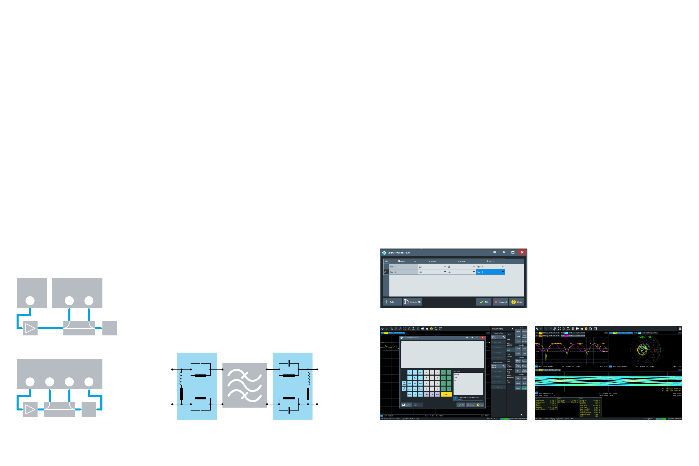
CONVENIENT CHARACTERIZATION OF
ACTIVE AND PASSIVE RFCOMPONENTS
Fast embedding/deembedding for impedance matching using
virtual networks
Coaxial and balanced components, such as SAW filters
used in mobile phone frontends, are specified together
with the networks that match them to the impedance of
the surrounding circuit. The R&S®ZNB can embed the DUT
into virtual matching networks to provide realistic conditions by simulating the DUT installed in its operational
environment. The R&S®ZNB offers a choice of predefined
matching network topologies. If values of individual network elements are edited, the R&S®ZNB immediately
recalculates the network and embeds the DUT in the new
network in real time. In addition to predefined topologies, .s2p, .s4p, .s6p and .s8p files can be read into the
R&S®ZNB and used for embedding/deembedding.
Redefined S-parameters
Mixed-mode S-parameters for balanced DUT characterization
To characterize a DUT with two balanced ports, the
R&S®ZNB treats the DUT like an unbalanced 4-port device.
It calculates the 16single-ended S-parameters and converts them to mixed-mode S-parameters. This additional
computational effort does not compromise measurement
speed. A wizard guides the user through the individual
steps of the measurement – fast and straightforward.
Redefined S-parameters for flexible test setup configuration
The R&S®ZNB can be flexibly configured to meet
application- specific requirements. The analyzer firmware
allows reconfiguring the physical ports by assigning them
waves as required for a specific task. This feature can be
used to integrate external components into the test set.
Extensive analysis functions for efficient traceanalysis
A wide variety of analysis functions help the user evaluate
important parameters at a glance:
►
Up to ten markers per trace
►
Automatic bandwidth measurements
►
Limit line and ripple check with pass/fail indication
►
Statistical trace analysis including maximum,
minimum, RMS and peak-to-peak detection as well as
compression point measurement
►
Equation editor for complex, real-time trace
mathematics
Amplifier measurements with wide power sweep range and
receiver step attenuators
The wide, electronically adjustable power sweep range
of the R&S®ZNB from –85dBm to +13dBm enables fast
analysis of the linear and nonlinear characteristics of small
and large-signal amplifiers. Electronic step attenuators in
the receive paths increase the 0.1dB compression point
to +27dBm. The wear-free attenuators feature delayfree switching, which enhances measurement speed and
extends the useful life of the R&S®ZNB in production.
Additional features:
►
Four DC inputs for measuring amplier DC power
consumption and efciency
►
Measurement of stability factors of balanced and
unbalanced ampliers
►
Support of R&S®NRP-Zxx power sensors, providing
high-precision power versus power and power versus
frequency measurements
Time domain analysis for distance-to-fault (DTF)
measurements and filter adjustment
The R&S®ZNB offers powerful time domain analysis to
measure components such as filters or high-speed digital data cables in the frequency and time domain. The
extended time domain analysis option makes it possible
to display eye diagrams for different bit patterns simultaneously with measurements in the frequency and time
domain.
With 100 000 points per trace, the R&S®ZNB measures
even electrically long DUTs such as long cables without
any problems. The gating function of the R&S®ZNB makes
it easy to locate cable faults and analyze them in detail.
Using prediction, the analyzer's frequency range can
be virtually extended by a factor of up to 10. This yields
resolution substantially higher than would be expected
from the upper frequency limits of 4.5GHz, 8.5GHz and
20GHz. For many applications, this eliminates the need
for a higher-frequency – and more expensive – network
analyzer.
External
source 1
Amplifier Dual directional coupler
Vector network analyzer
1 2 3 4
Amplifier Coupler
Vector network
analyzer
1 2
DUT
Reconfigured
physical port 1
a wave: b
b wave: b
Source: external
source 1
DUT
Reconfigured
physical port 1
a wave: b
b wave: b
Source: port 1
Reconfigured
physical port 2
a wave: a
b wave: b
Source: port 4
1
2
Menu for defining physical ports.
Impedance matching using virtual networks
C1
2
3
4
4
L1
R1
R2
R3
C2
Embedded network
DUT
C1
L1
R1
R2
R3
C2
Embedded network
Equation editor for trace mathematics.
Rohde & Schwarz R&S®ZNB Vector Network Analyzer 76
Simultaneous display of eye diagrams and measurements in the frequency and time
domain.
Page 5

Frequency-converting measurements on mixers and amplifiers
– fast and simple with two independent internal sources
When equipped with the frequency conversion
(R&S®ZNB-K4) and intermodulation measurements
(R&S®ZNB-K14) options, the R&S®ZNB measures harmonics and intermodulation products on amplifiers as well as
conversion loss, matching and isolation on mixers – both
in the frequency and time domain. A special calibration
technique – R&S®SMARTerCal – combines power calibration with system error correction to precisely determine
the magnitude of the conversion loss of mixers. Wizards
guide the user step by step to the desired setup and
through calibration.
Typical test setup for a mixer measurement
For complex measurements, such as on frontends with
multiple mixer stages, the R&S®ZNB can control multiple
external signal sources via LAN or IEC/IEEE bus.
The R&S®ZNB 4-port models can optionally be equipped
with a second, independent internal source, which can be
used, for example, as a local oscillator in mixer measurements or to deliver the second tone in intermodulation
measurements. This feature boosts measurement speed
by a factor of up to 10 compared with setups using an
external, IEC/IEEE bus controlled source. Plus, it significantly simplifies the test setup.
SIMPLE CALIBRATION–
MANUALORAUTOMATIC
The right calibration for every test application
The R&S®ZNB supports all common calibration methods
for coaxial DUTs as well as calibration methods for measurements on DUTs in test fixtures and on printed boards.
Graphical wizards guide the user step by step through the
calibration.
►
TOSM calibration (Through, Open, Short, Match)
►
TRL/LRL calibration (Through, Reect, Line/Line,Reect,
Line) for printed board based test structures and
on-wafer applications
►
TRM calibration (Through, Reect, Match) for
applications using test xtures
►
UOSM calibration (Unknown Through, Open, Short,
Match) for DUTs equipped with different types of
input and output connectors and for calibration with
an unknown through standard. Compared with the
conventional adapter removal calibration method,
this method reduces the number of calibration steps
from 14to 7. This saves time and reduces the risk of
calibration errors.
Typical effective system data (best value from each
frequencyrange)
Through, Short, Match (TSM) – full calibration in only
fivesteps
A network analyzer's accuracy after calibration essentially
depends on the quality of the calibration standards used.
The quality of the standards, in turn, depends mainly on
how accurately the standards can be described by models. Describing the open standard using a model may be
problematic. Rohde & Schwarz therefore created the TSM
calibration method for the R&S®ZNB. This method requires
only a through, a short and a match; an open standard is
not needed. TSM provides accuracy equivalent to that of
TOSM, and reduces the number of calibration steps from
seven to five.
Automatic calibration units with up to 24 ports
Rohde & Schwarz offers automatic calibration units with up
to 24ports. The units are immediately ready for operation
when connected to an R&S®ZNB. Users can connect
adapters to their calibration units to match different
connector types used on the DUT. They can recharacterize
the calibration unit, together with the adapters, and store
the resulting data to the unit's internal memory. The
R&S®ZN-Z51 calibration unit is a special version that can
be factory-configured with a mix of connectors.
LO
RF IF
Wizard for configuring mixer measurements.
R&S®ZNB4/
R&S®ZNB8
Directivity 46dB 46dB
Source match 41dB 43dB
Load match 45dB 45dB
Reflection tracking 0.02dB 0.05dB
Transmission tracking 0.018dB 0.03dB
R&S®ZN-Z51 4-port calibration unit equipped with different types of connectors.
R&S®ZNB20
R&S®ZNB calibration wizard.
Rohde & Schwarz R&S®ZNB Vector Network Analyzer 98
Page 6

NETWORK ANALYSIS MADE EASY
The R&S®ZNB vector network analyzers turn into reality what many users desire:
configuration, measurement and analysis that are truly intuitive.
Flat and clear menu structures for efficient operation
The R&S®ZNB groups together logically related analyzer
control functions at a single operational level, doing away
with submenus and multilevel, nested menu structures.
►
The R&S®ZNB features a soft panel that immediately
shows all control elements that may be needed for
a measurement and effectively helps users perform
measurement tasks
►
Via the soft panel, users can access all instrument
functions in a maximum of three operating steps
►
Pop-up menus allow many test parameters to be
dened right where they are displayed
►
Wizards guide the user through the steps of an
operating sequence, for example when calibrating the
network analyzer, thereby reducing operator errors to a
minimum
Large color touchscreen (12.1")
Clearly arranged display of a large number of traces
Efficient operation with touch gestures
Whether zooming, moving traces or adding markers:
touch gestures make the R&S®ZNB very efficient to
operate.
Optimal display configuration for each measurement task
The R&S®ZNB features a brilliant 12.1" WXGA color touchscreen. The user can set up the display as required by
arranging diagrams, traces and channels in any desired
combination. Traces can simply be dragged and dropped
between diagrams, either with a finger or the mouse. The
names of traces, channels and markers can be edited and
replaced with user-specific names to make them easier to
identify and to provide consistent result documentation.
Soft panel
Optionally on the right or left, for direct instrument
control without submenus
With the R&S®ZNB, several instrument setups are available
simultaneously. The user simply touches or clicks a tab to
put the desired setup and diagrams in the foreground and
start the associated measurements.
This convenient approach makes it possible to handle
different measurement tasks simultaneously without overloading the display with diagrams that are not currently
needed.
The user can add further measurements for a given component without modifying the original measurement. This
function allows the user to very quickly switch between
setups, an essential prerequisite for high throughput in
production.
Toolbar
Fast access to frequently used functions
Preloaded setups
Switchover between instrument
setups by touching or clicking a tab
More than 100channels and traces
Fast characterization of sophisticated components
Pop-up menus
Fast access to desired function
Logically arranged hardkeys
Just a few keystrokes to desired configuration
Online help
Context-sensitive, including remote control
commands
Undo/Redo
Cancels or restores the last one to six entries
USB connectors for auxiliary equipment
Connection of power sensor, automatic calibration
unit, mouse/keyboard, memory stick, etc.
Widely spaced ports
Easy connection of DUT; plenty of space
for connecting test cables
Transparent dialog windows
Traces remain visible
Rohde & Schwarz R&S®ZNB Vector Network Analyzer 1110
Page 7

HIGH THROUGHPUT INPRODUCTION
Short measurement times
The R&S®ZNB features short measurement times, a result
of fast synthesizer settling times, short sampling times due
to large IF bandwidths, high-speed data processing up to
the display and fast LAN or IEC/IEEE data transfer to the
controller.
The analyzer's large IF bandwidths enable fast sampling
times of less than 1µs per point. The large IF bandwidths,
combined with the short synthesizer settling times, yield
a total measurement time of no more than 4ms for a
frequency sweep covering 401 points.
High measurement speed due to wide dynamic range and
optimized IF bandwidths
Measurement speed for tests on high-blocking DUTs,
such as on base station duplex filters, is determined by
the required dynamic range and the corresponding IF
bandwidth. The R&S®ZNB features a dynamic range more
than 10dB higher than that of comparable products on
the market. This means that, at an IF bandwidth higher
by a factor of 10, the R&S®ZNB measures ten times faster
than comparable products at the same dynamic range.
The R&S®ZNB offers IF bandwidths from 1Hz to 10MHz,
settable in steps of 1, 1.5, 2, 3, 5, 7 and 10, for optimized
speed and dynamic range.
The R&S®ZNB offers up to 140dB dynamic range for a
10Hz IF bandwidth. For a sweep with 110dB dynamic
range covering 201points, the R&S®ZNB requires less
than 30ms, a value that is attractive for base station filter
manufacturers.
Segmented sweep tailored to device under test
When testing high-blocking DUTs such as repeater duplex
filters, high IF bandwidths are required in the passband
to provide short measurement times. In the stopband, on
the other hand, such tests require high output powers and
narrow IF bandwidths to provide the required dynamic
range.
The segmented sweep function divides the frequency axis
into segments. Sweep parameters such as output power,
IF bandwidth and number of points can be defined separately for each segment to optimally adapt to the DUT
characteristics. This increases measurement speed without any loss in accuracy.
Fast switching between instrument setups
To carry out complex measurements with different
instrument setups, R&S®ZNB users do not need to load
the setups from the hard disk each time. Once called, the
setups for the required measurements, including calculated data such as calibration values, remain available in
RAM. This reduces switching time, especially for measurements involving a large number of points. Switching
between setups in remote operation is virtually instantaneous. With manual operation, all the user has to do is
touch the screen to activate the setup needed for a desired
DUT or measurement.
Handler I/O interface for communication with external
partshandlers
Via the optional handler I/O interface, the R&S®ZNB can
communicate with an external parts handler. During a typical test cycle, a parts handler places the DUT into a holder
and sends the start signal for the measurement. On completion of the measurement, the parts handler removes the
DUT from the holder and sorts it according to predefined
criteria. Then the handler places a new DUT in the holder,
and the test cycle starts again. The R&S®ZNB can thus be
used to deliver fast, reliable results in automated tests,
which play a key role especially in production applications.
GPIB interface with bidirectional data transfer saves time in
production
The optional GPIB interface can be used to connect a controller for remote control of the R&S®ZNB. Data is transmitted bidirectionally on the 8-bit parallel bus. The data measured during a sweep is transferred to the controller while
the next sweep is already in progress. Data transfer time
on the R&S®ZNB is therefore virtually negligible.
RFFE GPIO interface for direct control of frontendmodules
A growing number of components such as filters,
switches and amplifiers need to be integrated into the
frontend modules of mobile devices such as smartphones
and tablets and need to communicate with each other.
Here, the RFFE bus defined by the MIPI® Alliance has
established itself as the de facto standard. The optional
RFFE GPIO interface (external box) allows RF frontend
modules in mobile devices to be directly controlled by the
R&S®ZNB to carry out measurements with the modules set
to diverse operating modes.
Dialog for configuring a segmented sweep.
Menu for configuring the RFFE GPIO interface.
Rohde & Schwarz R&S®ZNB Vector Network Analyzer 1312
Page 8

MEASUREMENTS ON UP TO
48PORTS
Expanding the number of ports with switch matrices
Components used in modern communications equipment, e.g. frontend modules in smartphones and tablet
PCs, support a growing number of frequency bands and
additional functions such as WLAN, Bluetooth® and GPS.
As a result, the number of RF ports on these modules is
also growing, not least due to the use of differential components. The R&S®ZNB in combination with one or two
Automatic assignment of test ports on the R&S®ZNB.
switch matrices provides a comprehensive solution for
complex measurements on modules with up to 48 ports.
The matrices from Rohde & Schwarz deliver full crossbar
measurements, allowing all S-parameters of a multiport
DUT to be determined.
Easy configuration at the push of a button
The R&S®ZNB controls switch matrices via LAN, USB
or a dedicated digital device control interface. With an
R&S®ZNB 4-port model, for example, two switch matrices with two input ports and 24 output ports each can
be combined to characterize DUTs with up to 48 ports.
Once a matrix is connected, the R&S®ZNB automatically
detects the matrix type and assigns the test ports so that
users can immediately start measuring. S-parameters,
waves and wave ratios are directly selected and displayed
on the R&S®ZNB user interface, eliminating the need for
additional software or macros to configure and control the
setup or measurement.
Fast measurements and excellent RFcharacteristics
The switch matrices from Rohde & Schwarz feature
exceptionally short switching times. Via a dedicated
device control interface, the R&S®ZNB controls the matrix
switches directly and synchronously with its internal test
sequences. This yields enhanced measurement speed
especially for sweeps covering a small number of points.
Featuring compact design and state-of-the-art electronic
switches, the R&S®ZN-Z84 and R&S®ZN-Z85 switch matrices exhibit low insertion loss. Other highlights include
good test port match and a high compression point allowing measurements on active DUTs with output power levels up to +20dBm.
Rohde & Schwarz offers calibration units with up to
24ports. This enables fast, automated calibration of the
R&S®ZNB together with the matrices connected to it.
Matrix solutions for every application
Rohde & Schwarz offers switch matrices for a variety of
applications. Matrix models with two or four inputs and up
to 24 outputs are available. Users can select the optimum
configuration for low insertion loss, maximum accuracy
and a high number of ports. The base unit contains six
outputs. The R&S®ZN-Z84 switch matrix can be enhanced
to offer up to 24 outputs by adding further ports in groups
of six. The R&S®ZN-Z84 covers the frequency range from
10MHz to 8.5GHz.
Multiport measurements up to 20GHz can be performed
using an R&S®ZN-Z85 switch matrix together with an
R&S®ZNB20 analyzer. The R&S®ZN-Z85 is available
with two inputs and six outputs or with four inputs and
12outputs.
It is also possible to combine a 4-port R&S®ZNB with a
matrix with two inputs (mixed configuration). The remaining 2 ports on the network analyzer can be used as regular
VNA ports offering the superior performance the R&S®ZNB
is known for.
Mixed configuration: analyzer and switch matrix plus
high-performance VNA ports
R&S®ZNB with two R&S®ZN-Z84 switch matrices.
R&S®ZN-Z84 or R&S®ZN-Z85 switch matrix with 4-port
R&S®ZNB, delivering 12outputs
R&S®ZNB port 1 R&S®ZNB port 2R&S®ZNB port 3 R&S®ZNB port 4
SP4T
SP4T
SP4T SP4T SP4T SP4T SP4T
Port 1
Port 2
Port 3
Port 4
SP4TSP4T
Port 5
SP4T
Port 6
SP4T
SP4T
SP4T SP4T SP4T SP4T SP4T
Port 7
Port 8
Port 9
Port 10
SP4T
SP4TSP4T
Port 11
R&S®ZN-Z154 24-port calibration unit.
Port 12
R&S®ZN-Z84 switch matrix with 2-port R&S®ZNB, delivering 24outputs
R&S®ZNB port 1 R&S®ZNB port 2
SP4T SP4T
SP4T
SP4TSP4T
SP4T
SP4T
SP4T
SP4T
SP4TSP4T
SP4T
SP4T
SP4TSP4T
SP4T
SP4TSP4T
1 2 3 4 5 6 7 8 9 10 11
High-performance
ports
SP4T
SP4T SP4T SP4T SP4T SP4T
Port 1
Port 2
Port 3
Port 4
Port 5
Rohde & Schwarz R&S®ZNB Vector Network Analyzer 1514
Port 6
SP4T
SP4T SP4T SP4T SP4T SP4T
Port 7
Port 8
Port 9
Port 10
Port 11
Port 12
SP4T
SP4T SP4T SP4T SP4T SP4T
Port 13
Port 14
Port 15
Port 16
Port 17
Port 18
SP4T
SP4T SP4T SP4T SP4T SP4T
Port 19
Port 20
Port 21
Port 22
Port 23
Port 24
Page 9

A WORTHWHILE INVESTMENT
ORDERING INFORMATION
Ready for the future
Industrial network analyzers have a useful life of ten years
or more, depending on the application. Measurement
tasks often change during this time.
The R&S®ZNB has a modular design, i.e. subassemblies
such as DC inputs, GPIB interface, power supply, controller and hard disk are inserted into slots on the rear.
The R&S®ZNB can be quickly upgraded for new measurement tasks. Keeping the R&S®ZNB up to date, such as by
installing a more powerful, next generation controller or
adding new functionality, involves only minimum downtime and service cost.
Soft panel menus for selecting language (left) and
remote control command set (right).
Upgrading test systems without rewriting systemsoftware
Network analyzers are the core of many test systems, for
example in RF component production. Using latest generation Rohde & Schwarz network analyzers, system performance can be significantly enhanced.
The R&S®ZNB supports the remote control command sets
of practically all other Rohde & Schwarz network analyzers
as well as those of other manufacturers' instruments.
Replacing an obsolete analyzer with an R&S®ZNB therefore
poses no problems. In most cases it is sufficient to verify the response of the R&S®ZNB during a measurement
sequence; there is no need for costly modifications in the
system software.
An analyzer that speaks the user's language
Many tasks are easiest solved in one's native language;
the R&S®ZNB therefore comes with a multilingual user
interface. Currently available languages include English,
French, Spanish, Russian, Chinese and Japanese.
Designation Type Frequency range Order No.
Base units
Vector network analyzer, 2 ports, 4.5GHz, type N R&S®ZNB4 9kHz to 4.5GHz 1334.3330.22
Vector network analyzer, 4 ports, 4.5GHz, type N R&S®ZNB4 9kHz to 4.5GHz 1334.3330.24
Vector network analyzer, 2 ports, 8.5GHz, type N R&S®ZNB8 9kHz to 8.5GHz 1334.3330.42
Vector network analyzer, 4 ports, 8.5GHz, type N R&S®ZNB8 9kHz to 8.5GHz 1334.3330.44
Vector network analyzer, 2 ports, 20GHz, 3.5 mm R&S®ZNB20 100kHz to 20GHz 1334.3330.62
Vector network analyzer, 4 ports, 20GHz, 3.5 mm R&S®ZNB20 100kHz to 20GHz 1334.3330.64
Options
Bias tees for 2-port R&S®ZNB4/R&S®ZNB8 R&S®ZNB-B1 100kHz to 4.5/8.5GHz 1316.1700.02
Bias tees for 4-port R&S®ZNB4/R&S®ZNB8 R&S®ZNB-B1 100kHz to 4.5/8.5GHz 1316.1700.04
Receiver step attenuator, port1, for R&S®ZNB4 R&S®ZNB4-B31 9kHz to 4.5GHz 1316.0185.02
Receiver step attenuator, port2, for R&S®ZNB4 R&S®ZNB4-B32 9kHz to 4.5GHz 1316.0179.02
Receiver step attenuator, port3, for R&S®ZNB4 R&S®ZNB4-B33 9kHz to 4.5GHz 1316.0262.02
Receiver step attenuator, port4, for R&S®ZNB4 R&S®ZNB4-B34 9kHz to 4.5GHz 1316.0433.02
Extended power range for 2-port R&S®ZNB4 R&S®ZNB4-B22 9kHz to 4.5GHz 1316.0210.02
Extended power range for 4-port R&S®ZNB4 R&S®ZNB4-B24 9kHz to 4.5GHz 1316.0233.02
Extended dynamic range for 2-port R&S®ZNB4
Extended dynamic range for 4-port R&S®ZNB4
Receiver step attenuator, port1, for R&S®ZNB8 R&S®ZNB8-B31 9kHz to 8.5GHz 1316.0191.02
Receiver step attenuator, port2, for R&S®ZNB8 R&S®ZNB8-B32 9kHz to 8.5GHz 1316.0204.02
Receiver step attenuator, port3, for R&S®ZNB8 R&S®ZNB8-B33 9kHz to 8.5GHz 1316.0162.02
Receiver step attenuator, port4, for R&S®ZNB8 R&S®ZNB8-B34 9kHz to 8.5GHz 1316.0440.02
Extended power range for 2-port R&S®ZNB8 R&S®ZNB8-B22 9kHz to 8.5GHz 1316.0227.02
Extended power range for 4-port R&S®ZNB8 R&S®ZNB8-B24 9kHz to 8.5GHz 1316.0240.02
Extended dynamic range for 2-port R&S®ZNB8 1) R&S®ZNB8-B52 9kHz to 8.5GHz 1319.4998.02
Extended dynamic range for 4-port R&S®ZNB8 1) R&S®ZNB8-B54 9kHz to 8.5GHz 1319.5007.02
Extended power range for 2-port R&S®ZNB20 R&S®ZNB20-B22 100kHz to 20GHz 1317.8950.02
Extended power range for 4-port R&S®ZNB20 R&S®ZNB20-B24 100kHz to 20GHz 1317.8967.02
2nd internal source for R&S®ZNB4/R&S®ZNB8
2nd internal source for R&S®ZNB20
Precision frequency reference R&S®ZNB-B4 1316.1769.02
GPIB interface R&S®ZNB-B10 1311.5995.04
Device control 3) R&S®ZNB-B12 1319.5088.02
Direct control cable 3) R&S®ZN-B121 1323.9290.00
Handler I/O (universal interface) R&S®ZN-B14 1316.2459.05
External RFFE GPIO interface R&S®ZN-Z15 1325.5905.02
External RFFE GPIO interface, including current and
voltagemeasurements
DC inputs R&S®ZNB-B81 1316.0004.02
Time domain analysis R&S®ZNB-K2 1316.0156.02
Extended time domain analysis
Distance to fault R&S®ZNB-K3 1350.5057.02
Frequency conversion
Intermodulation measurements 6) R&S®ZNB-K14 1317.8373.02
10MHz receiver bandwidth R&S®ZNB-K17 1316.1881.02
1mHz frequency resolution R&S®ZNB-K19 1317.8573.02
5)
2)
4)
1)
1)
2)
R&S®ZNB4-B52 9kHz to 4.5GHz 1319.4975.02
R&S®ZNB4-B54 9kHz to 4.5GHz 1319.4981.02
R&S®ZNB-B2 9kHz to 8.5GHz 1317.7954.02
R&S®ZNB20-B2 100kHz to 20GHz 1317.8980.02
R&S®ZN-Z15 1325.5905.03
R&S®ZNB-K20 1326.8072.02
R&S®ZNB-K4 1316.2994.02
1)
Cannot be combined with R&S®ZNB-B1 or R&S®ZNB4-B3x /R&S®ZNB8- B3x.
2)
Requires R&S®ZNB 4 -por t model.
3)
Required for direct control of R&S®ZN-Z84/R&S®ZN-Z85 switch matrix and R&S®ZN-Z15 exter nal RFFE GPIO interface.
4)
Requires R&S®ZNB -K2.
5)
Requires R&S®ZVAB-B4 4 for control of external sources v ia the IEC/IEEE bus.
6)
Requires R&S®ZNB-K4.
Rohde & Schwarz R&S®ZNB Vector Network Analyzer 1716
Page 10

Designation Type Frequency range Order No.
USB-to-IEC/IEEE adapter R&S®ZVAB-B44 1302.5544.02
Real-time measurement uncertainty analysis R&S®ZNB-K50 3644.5977.02
Real-time measurement uncertainty analysis, preinstalled R&S®ZNB-K50P 1338.1810.02
Easy deembedding R&S®ZNB-K210 1328.8592.02
In-situ deembedding R&S®ZNB-K220 1328.8605.02
Smart fixture deembedding R&S®ZNB-K230 1328.8611.02
Delta-L PCB characterization R&S®ZNB-K231 1328.8628.02
Accessories
Calibration kits (manual calibration)
Calibration kit, N, 50 Ω R&S®ZCAN 0Hz to 3GHz 0800.8515.52
Calibration kit, 3.5 mm (m) R&S®ZN-Z135 0Hz to 26.5GHz 1328.8157.02
Calibration kit, 3.5 mm (f) R&S®ZN-Z135 0Hz to 26.5GHz 1328.8157.03
Calibration kit, N (m) R&S®ZN-Z170 0Hz to 18GHz 1328.8163.02
Calibration kit, N (f) R&S®ZN-Z170 0Hz to 18GHz 1328.8163.03
Calibration kit, N, 50 Ω R&S®ZV-Z270 0Hz to 18GHz 5011.6536.02
Calibration kit, 3.5 mm R&S®ZN-Z235 0Hz to 26.5GHz 1336.8500.02
Calibration units (automatic calibration)
Calibration unit, 2 ports, SMA (f) R&S®ZN-Z151 100kHz to 8.5GHz 1317.9134.32
Calibration unit, 2 ports, N (f) R&S®ZN-Z151 100kHz to 8.5GHz 1317.9134.72
Calibration unit, 6 ports, SMA (f) R&S®ZN-Z152 100kHz to 8.5GHz 1319.6003.36
Calibration unit, 4 ports, SMA (f) R&S®ZN-Z153 100kHz to 8.5GHz 1319.6178.34
Calibration unit, 6 ports, SMA (f) R&S®ZN-Z154 100kHz to 8.5GHz 1319.5120.02
Additional ports 7 to 12, SMA (f) R&S®ZNZ154-B22 100kHz to 8.5GHz 1319.5136.22
Additional ports 13 to 18, SMA (f) R&S®ZNZ154-B32 100kHz to 8.5GHz 1319.5136.32
Additional ports 19 to 24, SMA (f) R&S®ZNZ154-B42 100kHz to 8.5GHz 1319.5136.42
Calibration unit, 2 ports, 3.5 mm (f) R&S®ZN-Z50 9kHz to 9GHz 1335.6904.30
Calibration unit, 2 ports, 3.5 mm (f) R&S®ZN-Z50 9kHz to 26.5GHz 1335.6904.32
Calibration unit, 2 ports, 3.5 mm (f) R&S®ZN-Z51 100kHz to 8.5GHz 1319.5507.32
Calibration unit, 4 ports, 3.5 mm (f) R&S®ZN-Z51 100kHz to 8.5GHz 1319.5507.34
Calibration unit, 2 ports, N (f)
Calibration unit, 4 ports, N (f)
Calibration unit, 4 ports, 3.5 mm (f) R&S®ZN-Z52 100kHz to 26.5GHz 1335.6991.30
Calibration unit, 2 ports, 3.5 mm (f) R&S®ZN-Z53 100kHz to 26.5GHz 1335.7046.32
Calibration unit, 2 ports, N (f) R&S®ZN-Z53 100kHz to 18GHz 1335.7046.72
Calibration unit, 8 ports, N (f) R&S®ZV-Z58 300kHz to 8GHz 1164.0638.78
Calibration unit, 6 ports, 3.5 mm (f) R&S®ZV-Z59 10MHz to 20GHz 1164.0450.36
Switch matrices
Switch matrix, 8.5GHz, 2 VNA ports to 6 test ports,
base unit, SMA (f)
Additional test ports 7 to 12, 4 VNA ports
Additional test ports 7 to 12, 2 VNA ports
Additional test ports 13 to 18, 4 VNA ports
Additional test ports 13 to 18, 2 VNA ports
Additional test ports 19 to 24, 4 VNA ports
Additional test ports 19 to 24, 2 VNA ports
Switch matrix, 20GHz, 2 VNA ports to 6 test ports,
base unit, SMA (f)
Additional test ports 7 to 12, 4 VNA ports
8)
12)
7)
7)
R&S®ZN-Z51 100kHz to 8.5GHz 1319.5507.72
R&S®ZN-Z51 100kHz to 8.5GHz 1319.5507.74
R&S®ZN-Z84 10MHz to 8.5GHz 1319.4500.02
9)
9)
10)
10)
11)
11)
R&S®ZN-Z84-B24 10MHz to 8.5GHz 1319.4969.24
R&S®ZN-Z84-B22 10MHz to 8.5GHz 1319.4969.22
R&S®ZN-Z84-B34 10MHz to 8.5GHz 1319.4969.34
R&S®ZN-Z84-B32 10MHz to 8.5GHz 1319.4969.32
R&S®ZN-Z84-B44 10MHz to 8.5GHz 1319.4969.44
R&S®ZN-Z84-B42 10MHz to 8.5GHz 1319.4969.42
R&S®ZN-Z85 10MHz to 20GHz 1326.4777.03
13)
R&S®ZN-Z85-B24 10MHz to 20GHz 1326.4831.26
Designation Type Frequency range Order No.
Test cables
N (m)/N (m), 50 Ω, length: 0.6 m/1 m R&S®ZV-Z91 0Hz to 18GHz 1301.7572.25/.38
N (m)/N (m), 50 Ω, length: 0.6 m/0.9 m R&S®ZV-Z191 0Hz to 18GHz 1306.4507.24/.36
N (m)/3.5 mm (m), 50 Ω, length: 0.6 m/1 m R&S®ZV-Z92 0Hz to 18GHz 1301.7589.25/.38
N (m)/3.5 mm (m), 50 Ω, length: 0.6 m/0.9 m R&S®ZV-Z192 0Hz to 18GHz 1306.4513.24/.36
3.5 mm (f)/3.5 mm (m), length: 0.6 m/1 m R&S®ZV-Z93 0Hz to 26.5GHz 1301.7595.25/.38
3.5 mm (f)/3.5 mm (m), length: 0.6 m/0.9 m/1.5 m R&S®ZV-Z193 0Hz to 26.5GHz 1306.4520.24/.36/.60
Hardware add-ons
19"rackmount kit, 2 RU (e.g. for R&S®ZN-Z84) R&S®ZZA-KN2 1175.3010.00
19"rackmount kit, 5 RU (e.g. for R&S®ZNB) R&S®ZZA-KN5 1175.3040.00
RF cable set, N (m)/3.5 mm (m), for connecting
two 2 × n-port R&S®ZN-Z84 switch matrices to a 4-port
R&S®ZN-Z28 10MHz to 8.5GHz 1326.6605.02
R&S®ZNB4 or R&S®ZNB8
Additional removable SSD, 512 Gbyte, Windows 10 R&S®ZNB-B19 1334.3860.03
VNA simulation
License dongle R&S®ZNPC 1325.6601.02
Simulation of R&S®ZNB, R&S®ZNBT, R&S®ZNC, R&S®ZND
TDR for VNA simulation
7)
Can be configured ex factor y with N (m/f), 3.5 mm (m/f), 7/16 (m/f) (see R&S®ZN-Z51 data she et, PD 36 06.8995.22).
8)
Includes c ables for connecting an R&S®ZN-Z84 switch matrix to an R&S®ZNB4/R&S®ZNB8 analyzer.
9)
Requires R&S®ZN-Z84.
10)
Requires R&S®ZN-Z84-B2x.
11)
Requires R&S®ZN-Z84-B3x.
12)
Includes c ables for connecting an R&S®ZN-Z85 switch matrix to an R&S®ZNB20 analyzer.
13)
Requires R&S®ZN-Z85.
14)
Requires R&S ®ZNPC.
15)
Requires R&S®ZNXSIM -K1.
15)
14)
R&S®ZNXSIM-K1 1334.4066.02
R&S®ZNXSIM-K22 1338.1632.02
Warranty
Base unit 3 years
All other items
1)
1 year
Options
Extended warranty, one year R&S®WE1
Extended warranty, two years R&S®WE2
Extended warranty with calibration coverage, one year R&S®CW1
Extended warranty with calibration coverage, two years R&S®CW2
Extended warranty with accredited calibration coverage, one year R&S®AW1
Extended warranty with accredited calibration coverage, two years R&S®AW2
1)
For options that are installed, the remaining base unit warranty applies if longer than 1 ye ar. Exception: all bat teries have a 1 year warrant y.
Please contact your local
Rohde & Schwarz sales
office.
For further information about the R&S®ZNB40, see product brochure (PD 5214.5384.12) and
data sheet (PD 5214.5384.22).
Your local Rohde & Schwarz expert will help you determine the optimum solution for your requirements.
To find your nearest Rohde & Schwarz representative, visit www.sales.rohde-schwarz.com
MIPI® marks and logos are ser vice marks owned by MIPI Alliance, Inc. and any use of such marks by Rohde & Schwarz is under license.
Rohde & Schwarz R&S®ZNB Vector Network Analyzer 1918
Page 11

Service that adds value
► Worldwide
► Local and personalized
► Customized and flexible
► Uncompromising quality
► Long-term dependability
Rohde & Schwarz
The Rohde & Schwarz electronics group offers innovative
solutions in the following business fields: test and measurement, broadcast and media, secure communications,
cybersecurity, monitoring and network testing. Founded
more than 80 years ago, the independent company which
is headquartered in Munich, Germany, has an extensive
sales and service network with locations in more than
70countries.
www.rohde-schwarz.com
Sustainable product design
►
Environmental compatibility and eco-footprint
►
Energy efciency and low emissions
►
Longevity and optimized total cost of ownership
Cert ied Quali ty Managem ent
IS O 9001
Certied Environmental Management
IS O 14 00 1
Rohde & Schwarz training
www.training.rohde-schwarz.com
Rohde & Schwarz customer support
www.rohde-schwarz.com/support
R&S® is a registered trademark of Rohde & Schwarz GmbH & Co. KG
Trade names are trademarks of the owners
PD 3608.3278.12 | Version 01.00 | May 2021 (ch)
R&S®ZNB Vector Network Analyzer
Data without tolerance limits is not binding | Subject to change
© 2021 Rohde & Schwarz GmbH & Co. KG | 81671 Munich, Germany
3608327812
3608.3278.12 01.00 PDP/PDW 1 en
 Loading...