

Page 1

1 110110 XD950 Transciever 50W
Z
ROHDE &SCHWAR
ND 950
Base
Station
System
Maintenance &
Faultfinding
Training
2 310601 RX Front End
3 310002 RX IF
4 300603 RX Synthesizer
5 310604 TX Exiter
6 300605 20W Power Amplifier
7 300606 50W Power Amplifier
8 300407 Directional Coupler
9 300408 RF Testloop Switch
10 300009 Control Board
11 310010 Analogue Board
12
13
Vol. 2
The information in this document is subject to
Change without notice. All rights reserved
Part of the document may be reproduced or
Transmitted in any form or by any means,
Electronic or mechanical, for any purpose,
Without written permission of Damm Cellular
Systems A/S.
Company or product names mentioned in this
Document may be trademarks or registered
Trademarks of the respective companies
Rev. 1.00
Date: 020731
. No
14
15
16
17
18
19
20
21
22
23
24
25
26
27
28
29
30
31
Page 2

Doc. No. Rev. Date
R110110_F01 1.00 02.06.04
Description
110110 TRANSCIEVER XD 950 50W
ND950/951
Base Station System
110110
XD950 Transceiver 50W
ND950training\manual\vol2\110110\R110110_F01 Page 1 of 1
Page 3

Doc. No. Rev. Date
R110110.IDX 1.00 02.06.04
Description
110110 TRANSCIEVER XD950 50W
110110 XD950 TRANSCEIVER 50W
INDEX :
Document Date Description
R110110-F01 970324 Front page
R110110-IDX 970507 Index
R110110-LST Parts list
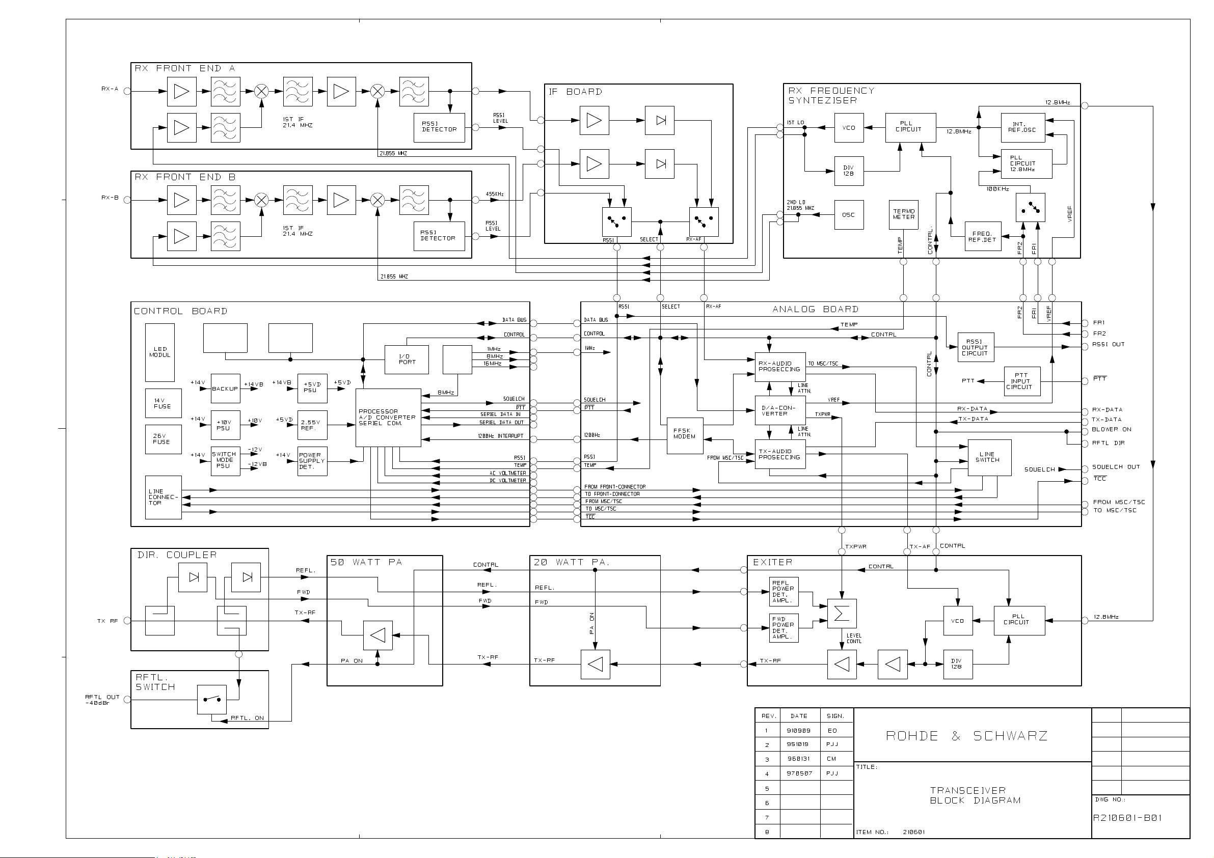
R210601-B01 970507 Block Diagram - Transciever
R210601-B02 950929 Block Diagram - Power Distribution
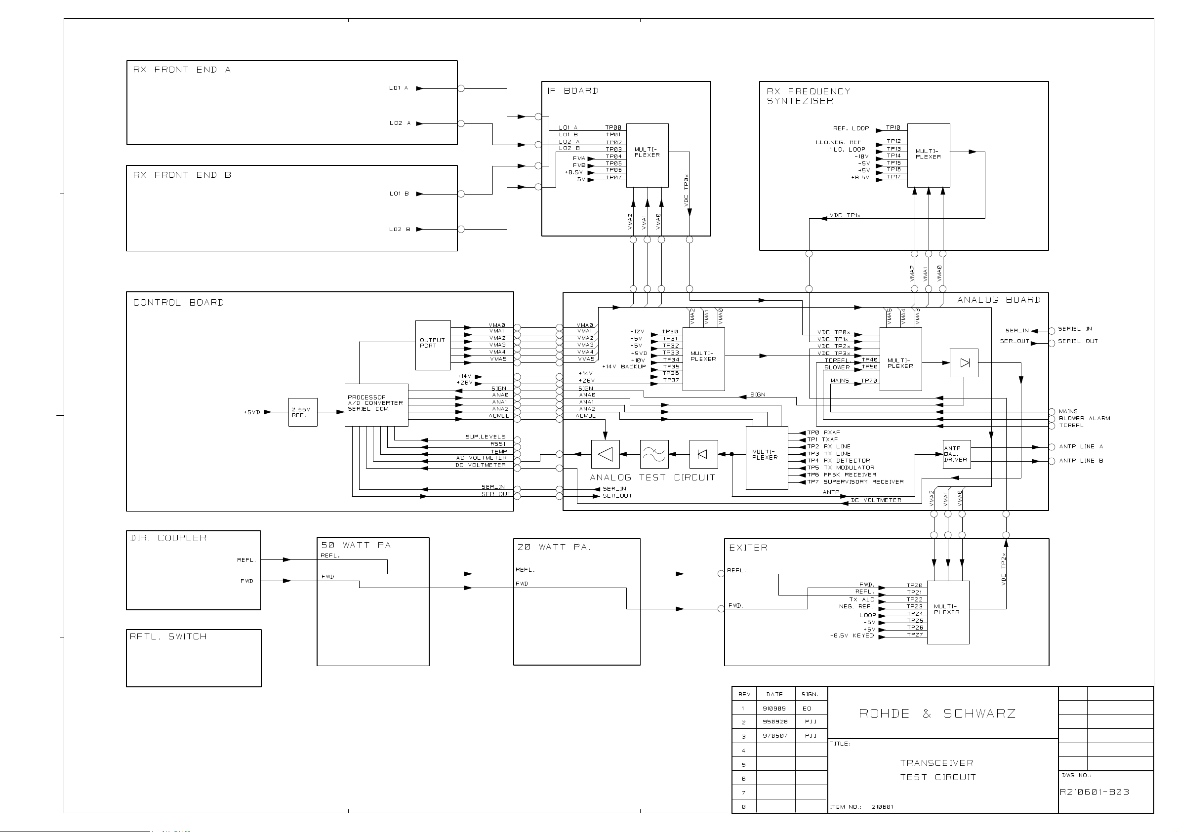
R210601-B03 970507 Block Diagram - Test Circuit
R210601-LST Parts list
XD950 990215 TR unit Functional Description
XD950 990215 XD950 TR unit help
210601-ADJ 020604 Adjustment procedure XD950
R200401-A01 961204 Assembly drawing
ND950training\manual\vol2\110110\R110110_IDX Page 1 of 1
Page 4

Doc. No. Rev. Date
2002-06-28R110110-LST
Description
Parts list: XD950 410-420MHz 50W transceiver
110110 XD950 410-420MHz 50W transceiver
Pos. Description Item No. Qty Unit
1 210601 XD950 410-420MHz 50W transceiver 1 pcs.
2 560001 Coax cable TNC/RG223/TNC 160mm 1 pcs.
3 560002 Coax cable BNC/RG223/BNC 160mm 1 pcs.
Page 1 of 1
Page 5
Page 6

Page 7
Page 8

Doc. No. Rev. Date
2001-09-25R210601-LST
Description
Parts list: XD950 410-420MHz 50W transceiver
210601 XD950 410-420MHz 50W transceiver
Pos. Description Item No. Qty Unit
1 300011 13-pol. connector module 1 pcs.
2 300012 23-pol. connector module 2 pcs.
3 300013 Termination 50 ohm 2-pin 2 pcs.
4 518001 R&S front plate for XD950 1 pcs.
5 530112 Cabinet+cover for 50W transceiver 1 pcs.
8 300017 Frequency reference cable 1 pcs.
9 562104 Power cable for transceiver 1 pcs.
10 800106 Handle for TR/SR 1 pcs.
11 800105 Thread nipple M2.5 steel 2 pcs.
15 810001 Insulator sleeve 3.5/3.1 1 pcs.
17 563002 Etronit plate 315x107x0.5 1 pcs.
19 810601 Cover plastic Ø12/16mm 1 pcs.
20 810703 Binding sleeve A2 1 pcs.
21 562004 Cable 6-pol. for front-end 1 pcs.
101 870404 Screw M2.5x5 CHJL Z 31 pcs.
102 870405 Screw M2.5x6 CHJL Z 2 pcs.
104 870407 Screw M2.5x10 CHJL Z 2 pcs.
105 870613 Screw M4x25 CHJL Z 6 pcs.
106 870590 Screw M3x6 flange head JU Z 2 pcs.
107 870504 Screw M3x6 CHJL Z 3 pcs.
108 873403 Screw M2.5x6 UHJX Z 8 pcs.
109 873601 Screw M4x6 UHJX Z 4 pcs.
110 877502 Screw M3x8 UHJU Z 2 pcs.
111 875675 Screw M4x6 LHRX 4 pcs.
113 800104 Screw M2.5 for front plate 2 pcs.
203 884001 RF gasket 3mm 1650 mm
900 517005 Label "Warning! R&S BASE STATION" 1 pcs.
901 517008 Label 40x32mm 1 pcs.
M1 310601 RX front-end 410-420MHz R&S 1 pcs.
M2 - Not used 0 pcs.
M3 310002 RX IF board R&S 1 pcs.
M4 300603 RX freq.synthesizer 410-420MHz 1 pcs.
M5 310604 R&S Exciter 420-430MHz 1 pcs.
M6 300605 20 W PA 400-440MHz 1 pcs.
M7 300606 50 W PA 420-430MHz 1 pcs.
M8 300407 Directional coupler 400-500MHz 1 pcs.
M9 300408 RFTL switch 1 pcs.
M10 300009 Control board 0 pcs.
M11 310010 Analog board R&S 1 pcs.
Page 1 of 1
Page 9

Doc. No. Rev. Date
990215
Description
XD950 TR unit help
XD950 TR unit help
TR Functional Description
TR FUNCTIONAL DESCRIPTION
All test commands for the base station transceiver consist of a 2-digit command in the range 00 to 99
with an optionally parameter. Commands without parameters are display-only commands and will not
make any change in the TR. Therefore, it is possible to "page through" the commands to find the right one
without any risk to change vital parameters.
The commands are divided into groups, covering the different functions in the TR. For example, all the
TX commands are in the 10 to 19 group.
If the first two characters are not representing a valid number in the 00 to 99 range, an error message will
be displayed:
INVALID TR COMMAND
This is however not the case if the first character is a + , which are reserved for commands to the test
box, and for strings of the format !hhhhhh, which is used for transfer of alarms from the CCU to the TR.
In these cases no response will be sent.
MSC/TSC/LOCAL CONTROL MODE
After power-on, the TR always starts in MSC/TSC-mode. If a given command requires local blocking, it
is shown in the help for the command. Commands that requires local blocking is not available under
MSC/TSC control, to protect the normal operation of the base station. If a protected command is called,
the following response is displayed:
LOCAL BLOCKING NECESSARY
Only commands with a parameter are protected. After activation of local blocking (01+), all the
commands are available.
PARAMETERS
Two types of parameters are used.
Generally + is used as parameter to turn on, enable or step up and - is used as parameter to turn off,
disable or step down.
For more complex functions, a / is used as separator after the command no. followed by the necessary
no. of characters for the actual function.
If the parameter is not valid for the actual command, the following response is displayed:
Licensed user: Hans Damm Research A/S
Page 1 of 57
Page 10

Doc. No. Rev. Date
990215
Description
XD950 TR unit help
INVALID PARAMETER
SETTINGS
Many calibration and system parameters are stored residently in the micro- processors built-in
EEPROM. At power-up and reset all settings are copied into the workspace RAM, from where the
different software tasks takes the settings.
Any change in the settings is only made in the workspace RAM. To store the new setting residently, a
programming command shall be made for the specific setting. This has a standard format for all settings
(xx/EE++++). If the programming succeeded, the following response is displayed:
SETTING STORED IN EEPROM
If a failure during programming is detected, the following response is dis- played:
EEPROM PROGRAMMING ERROR
The programming command string has been made rather complex to limit the risk of accidential change of
the resident settings. The resident settings are restored into the workspace RAM at software reset (02+)
or local deblocking (01-) if local blocking was selected.
Licensed user: Hans Damm Research A/S
Page 2 of 57
Page 11

Doc. No. Rev. Date
Description
XD950 TR unit help
General commands
00 DISPLAY SOFTWARE VERSION NUMBER
00 Display software version number
00
Command description:
Response:
1) R&S 410 MHz BS VER. 1.20
Description:
Displayes the software version number in the EPROM on the control board.
01 LOCAL BLOCKING/DEBLOCKING
990215
01 Local blocking: Display state
01
01+ Local blocking: Conditional request
01+
01++ Local blocking: Forced request
01++
01- Local blocking: Off
01-
Command description:
Response:
1) LOCAL BLOCKING: OFF
2) LOCAL BLOCKING: ON
3) LOCAL BLOCKING: REQ
Description:
The local blocking command has the purpose to tell the MSC/TSC, that a technician wants to make
service on the TR, and that the MSC/TSC shall take it out of normal operation. Additionally, it protects
the technician to perform many of the test commands during normal operation, which could desturb the
ongoing calls.
The 01+, 01++ and 01- commands has no effect, if the state is already present.
The 01+ command makes a local blocking request. If the supervisory RX is activated (indicating, that the
channel is currently occiopied of a call), the LOC LED will flash to indicate the request. During this
period, "LOCAL BLOCKING: REQ" is returned.
During the request period, a 01- command will only clear the request.
Licensed user: Hans Damm Research A/S
Page 3 of 57
Page 12

Doc. No. Rev. Date
990215
Description
XD950 TR unit help
If forced local blocking 01++ is given or as soon the SUP. RX is off after a local blocking request 01+,
frame 28 V1(6), V2(15), V3(6) is sent to MSC/TSC, the red LOC indicator on the front plate turns on
and responds to the MSC/TSC commands stops. All current states and selections, when the local
blocking was executed, will be maintained. Now all the listed commands will be acces- sible for the
technician.
If local deblocking 01- is selected from ON, the TR performs a software reset sequence equivalent to
the power-on reset sequence, and sends a frame 28 V1(9), V2(15), V3(6) local deblocking to inform
the MSC/TSC, that it now can put the TR into normal operation again. The red LOC indicator is
switched off.
If local blocking 01+ or 01++ is selected before mains return has been sent after power-on, the local
blocking frame is not sent to MSC/TSC.
02 SOFTWARE RESET
02 Display command function
02
02+ Execute software reset
Local blocking necessary
02+
Command description:
Response:
1) SOFTWARE RESET BY 02+ 02 response
2) EXECUTES SOFTWARE RESET 02+ response
Description:
Software reset performs exactly the same tasks as the power-on reset sequence with one exception. It
can only be activated, if local blocking has been selected, and after the reset sequence, the local blocking
will be maintained.
The software reset is a very convenient way to bring the TR back to a known state. The software reset
also restores the nonvolatile settings of the EEPROM in the workspace RAM to remove the nonstored
changes in settings.
03 ALARM DISPLAY AND RESET
03 Display alarm state
03
03+ Execute alarm reset
03+
03/1 Display latched local alarms
03/1
Licensed user: Hans Damm Research A/S
Page 4 of 57
Page 13

Doc. No. Rev. Date
Description
XD950 TR unit help
03/2 Display latched CCU alarms
03/2
03/C1 Display current local alarms
03/C1
03/C2 Display current CCU alarms
03/C2
Command description:
Response:
1) ALARMS: L=xx C=xx 03 response
2) ALARM RESET EXECUTED 03+ response
3) xxxxxxxxxxxxxxxx 03/1 and 03/C1 response
4) xxxxxxxxxxxxxxxxxxxxxxxx 03/2 and 03/C2 response
990215
Description:
The 03 command displayes the number of alarms. The latched alarm count (L) is the number of alarms
sent to the MSC/TSC. The current alarm count (C) is the number of alarms present, when 03 is
executed and followes the current evaluation.
The alarms are transferred to the latched alarm registers, when they are sent to the MSC/TSC. If local
blocking has been selected, the alarms are not sent to MSC/TSC and thereby not transferred to the
latched registers. The alarms will remain in the latched registers, even when conditions for the alarm are
not longer fulfilled, until an alarm reset is executed.
The 03+ command resets all the latched alarms. If the alarms are still present, it will force them to be sent
to the MSC/TSC again. The alarm reset frames 22 V1(1) for TR has the same function as the 03+
command.
The 03/1 and 03/C1 displayes the state of the individual alarms generated internally in the TR.
The 03/2 and 03/C2 displayes the state of the individual alarms sent from the CCU.
The display can show three different characters:
0 No alarm
N Nonblocking alarm
B Blocking alarm
The alarm LED’s will be on, if the latched or current or both registers are set.
The 66 command can point out the actual cause for TX, RX and CU alarms.
The 03/1 and 03/C1 displayed flags are:
DESCRIPTION: V(1),V(2),V(3):
------------ ---------------
1. TX LEVEL 2 6,15,14
Licensed user: Hans Damm Research A/S
Page 5 of 57
Page 14

Doc. No. Rev. Date
Description
XD950 TR unit help
2. TX LEVEL 1 10,15,1
3. RX LEVEL 2 6,15,7
4. (RX LEVEL 1)
5. CU 6,15,9
6. SUPERVISORY TEST LOOP 6,15,2
7. COOLING FAN 10,15,14
8. TX COMBINER TEST POINT (ANT L1) 10,15,0
9. MASTER OSCILLATOR L2 (TX L2) 6,15,14
10. MASTER OSCILLATOR L1 10,15,13
11. TX OUTPUT VSWR (ANT L1) 10,15,0
12. CCU TIMEOUT ALARM 10,8,15
13. (spare)
14. (spare)
15. (spare)
16. (spare)
The 03/2 and 03/C2 displayed flags are:
990215
DESCRIPTION: V(1),V(2),V(3):
------------ ---------------
1. TX ANTENNA LEVEL 2 6,15,15
2. TX ANTENNA LEVEL 1 10,15,0
3. RX MULTICOUPLER LEVEL 2 6,15,13
4. RX MULTICOUPLER LEVEL 1 10,15,15
5. (spare)
6. (spare)
7. (spare)
8. (spare)
9. HOUSE 10,1,7
10. HOUSE 10,1,6
11. MAINS W. BATTERY BACKUP 10,1,5
12. HOUSE 10,1,4
13. OBSTRUCTION LIGHT 10,1,3
14. INTRUDER 10,1,2
15. HOUSE 10,1,1
16. FIRE 10,1,0
17. COMMON CONTROL UNIT 10,8,15
18. EXTERNAL 10,8,14
19. EXTERNAL 10,8,13
20. EXTERNAL 10,8,12
21. EXTERNAL 10,8,11
22. EXTERNAL 10,8,10
23. EXTERNAL 10,8,9
24. EXTERNAL 10,8,8
The alarm reset command also has the function to reset the sequence of locking to the external frequency
references. If local blocking has not been selected, the TR will retry to lock to FR1, if it is locked to FR2
or is running stand-alone.
Licensed user: Hans Damm Research A/S
Page 6 of 57
Page 15

Doc. No. Rev. Date
Description
XD950 TR unit help
04 SELFTEST
04 Display last selftest result
04
04+ Start Channel selftest (including RX antenna)
Local blocking necessary
04+
04- Start Channel selftest (excluding RX antenna)
Local blocking necessary
04-
04/1 Display selftest error flags
Local blocking necessary
04/1
990215
Command description:
Response:
1) LAST SELFTEST: COMPLETED 04 response
2) LAST SELFTEST: FAILED 04 response
3) SELFTEST STARTED 04+ response
4) SELFTEST ERRORS:xxxxxxxx 04/1 response
Description:
The 04+ and 04- commands activates the channel selftest function, which can also be activated from the
MSC/TSC of frame 22 V1(4). The selftest will only succeed, if the TR is mounted in a complete system
with an RFTL converter mounted. It has no meaning for a stand-alond TR.
The 04+ and 04- commands are identical except that the 04- command do not include the RX antenna
test. The 04- command can be used together with the CCU Batch B/04- to make simultanuously selftest
on several Channel Units. The 04+ command includes the RX antenna test and will not work proporly
with the Batch command.
The selftest is made according to the RX diversity configuration (07 command). If a single RX input is
configured, the selftest command is completed in about 4 seconds. If diversity is selected, the 04+ and
04- commands initiates a complete selftest procedure for the RXA as well as the RXB paths and takes
about 8 seconds to complete.
Selftest initiated from the MSC/TSC includes the RX antenna test and should therefore not be initiated
on several channels simultaneously. The MSC/TSC initiated selftest will only test one RX path to meet
the maximum specified completion time of 5 seconds. If diversity is provided, the selftest will alternate
between the two RX paths each time it is activated.
The inclusion of the RX antenna test is depending of the setting of the 79 command. If 79- has been
selected, the RX antenna test will not be included. The 79- setting shall be selected, if the TR is installed
in a system, where the RX antenna test facility is not provided.
The selftest sequence executes the following functions:
Licensed user: Hans Damm Research A/S
Page 7 of 57
Page 16

Doc. No. Rev. Date
990215
Description
XD950 TR unit help
1) Initially it keys the TX, turns on the RFTL switch, modulates the TX
with a 1200 Hz tone with a deviation of 3 kHz, turns on the supervisory
system, switches the AC voltmeter to testpoint no. 4 and selects an RX
measuring path.
2) Waits for about 3 seconds to give time for the supervisory detector to
stabilize.
3) Tests the returned AF level to be within +/-6dB with the AC voltmeter.
4) Tests for supervisory L2 to be exceeded.
5) Tests for the returned RSSI signal to be within +2/+14 dBuV.
6) Activates the RFTL Converter output direction switch if RX antenna test
shall be included. Else it continues with 9).
7) Waits 0.2 sec.
8) Tests the RX antenna and deactivates the RFTL direction switch.
9) Repeats 2) to 8) with other RX path if necessary.
10) Stops the TX, turns off the RFTL switch, stops the 1200 Hz tone, turns
off the supervisory system, switches the AC voltmeter to testpoint no. 0
and restores the RX diversity selection according to the 07 setting.
All the tests sets or clears the corresponding error flags.
The 04 command shows, whether the last selftest has failed or has completed correctly.
The 04/1 command displayes the individual error flags from the selftest, which has the following meaning:
1. RXA: AF LEVEL NOT WITHIN +/-6 dB
2. RXA: SUPERVISORY LEVEL 2 ALARM
3. RXA: RSSI NOT WITHIN +2/+14 dBuV
4. RXA: RX ANTENNA REFLECTION LOSS LOWER THAN 79 SETTING
5. RXB: AF LEVEL NOT WITHIN +/-6 dB
6. RXB: SUPERVISORY LEVEL 2 ALARM
7. RXB: RSSI NOT WITHIN +2/+14 dBuV
8. RXB: RX ANTENNA REFLECTION LOSS LOWER THAN 79 SETTING
07 RX DIVERSITY CONFIGURATION
07 Display RX Configuration
07
07/A Select RXA only
07/A
07/B Select RXB only
07/B
Licensed user: Hans Damm Research A/S
Page 8 of 57
Page 17

Doc. No. Rev. Date
990215
Description
XD950 TR unit help
07/D Select diversity RX
07/D
07/EE++++ Store RX Configuration in EEPROM
++++
07/EE....
Command description:
Response:
1) RX CONFIGURATION: A
2) RX CONFIGURATION: B
3) RX CONFIGURATION: D
Description:
The 07 commands have the purpose to tell the software the actual configuration of the system.
After reset, the stored configuration inits the appropriate setting controlled by the 22 commands.
The setting controls the RX selection at power-up and software reset.
The setting changes the the alarm handling from the RX multicouplers. If A or B is selected, it will
generate a blocking RM alarm, if an RMA or RMB alarm respectively is present. If D is selected, a
redundant RM alarm is genereted, if RMA or RMB alarm is present, and a blocking RM alarm, if both
RMA and RMB alarm is present.
The setting also controls the tasks of the selftest commands 04+ and 04-.
Licensed user: Hans Damm Research A/S
Page 9 of 57
Page 18

10 TX KEY
10 Display TX state
10
10+ Turn on TX
Local blocking necessary
10+
10- Turn off TX
Local blocking necessary
10-
10/T Toggle TX on/off
Local blocking necessary
10/T
Doc. No. Rev. Date
990215
Description
XD950 TR unit help
Transmitter commands
Command description:
Response:
1) TX OFF
2) TX ON
3) TX ON PLL: UNLOCKED
Description:
The commands control the TX key function
The 10 command displayes the actual state of the TX.
The 10+ command executes the TX on sequence, if the TX is not already keyed.
The 10- command executes the TX off sequence, if it is not already off.
If the TX is on and the PLL is not locked, the response no. 3) will be returned.
The TX on and off sequences are rather complex, and involves the exciter key, the PA key, the DAC
power setting and the TX fast/slow lock switch. Serial transfer of data to the shift registers is also done at
TX on.
11 DISPLAY TX OUTPUT AND REFLECTED POWER
11 Display TX output and reflected power
11
Command description:
Response:
1) TX: OUT=xx.xW REFL=xx.xW
Licensed user: Hans Damm Research A/S
Page 10 of 57
Page 19

Doc. No. Rev. Date
990215
Description
XD950 TR unit help
Description:
The command displayes the actual forward and reflected power measured with the internal directional
coupler through DC test point 10 and 11. The DC reading is converted to power with a conversion table
stored in the EPROM.
The 90 commands are used to factory adjust the power meter.
12 DISPLAY TX COMBINER TESTPOINT VALUE
12 Display TX combiner TP value
12
Command description:
Response:
1) TX COMBINER TP: x.xx VDC
Description:
The command shows the DC voltage from the detector mounted on the load on the circulator closest to
the channel filter for the actual TR. It shows the relative size of the power reflected from the filter together
with the power from the other transmitters, which leaks through the filter.
The command is used under adjustment of the channel filter. After a C/12 command, the channel filters
tuning screw is just turned to minimum reading without any use of external measuring equipment.
The command is also used to determine the desired alarm level setting in the 78 command.
13 TX POWER LEVEL
13 Display TX power level number
13
13/n Setup TX power level number
Local blocking necessary
Power level number (1..3)
13/.
13/EE++++ Store TX power level number in EEPROM
Local blocking necessary
++++
13/EE....
Command description:
Response:
1) TX POWER LEVEL = x x = 1, 2 or 3
2) INVALID TX POWER LEVEL
Licensed user: Hans Damm Research A/S
Page 11 of 57
Page 20

Doc. No. Rev. Date
990215
Description
XD950 TR unit help
Description:
The commands are used to switch the transmitter between the three preadjusted power levels, which are
factory adjusted to 1.5W, 6W and 25W.
The 3 levels can be individually adjusted over the whole possible power range by the 81, 82 and 83
command respectively.
14 DISPLAY TX FREQUENCY DEVIATION
14 Display TX deviation
14
Command description:
Response:
1) TX DEVIATION = x.xx kHz
2) TX DEVIATION = Uncalib.
Description:
The 14 command displayes the TX modulation (frequency deviation) actually present on the transmitter.
The measured value is the mean value of the deviation, but it is calibrated in peak value.
For a system with 25 kHz channel spacing the following nominal values are given:
1) 1kHz standard modulation: 3.00 kHz
2) FSK modulation : 3.50 kHz (mean value of 2.80 and 4.20 kHz).
The measurement is made with the build-in AC voltmeter on TP number 5. After the 14 command has
been executed, this TP will be selected.
The reading is factory calibrated with the 94 command. When software is upgraded to ver. 1.40 or
newer on units, where calibration with the 94 command has not been done, "Uncalib." will be displayed.
17 TX PLL LOOP SPEED
17 Display TX loop speed
17
17+ Select fast TX loop
Local blocking necessary
17+
17- Select slow TX loop
Local blocking necessary
17-
Command description:
Response:
Licensed user: Hans Damm Research A/S
Page 12 of 57
Page 21

Doc. No. Rev. Date
990215
Description
XD950 TR unit help
1) TX LOOP: SLOW
2) TX LOOP: FAST
Description:
The command controls the PLL speed switch on the Exciter Board, and are implemented for test and
repair.
It shall not be used during normal operation.
18 PA KEY
18 Display PA key state
18
18+ Turn on PA key
Local blocking necessary
18+
18- Turn off PA key
Local blocking necessary
18-
Command description:
Response:
1) PA: ON
2) PA: OFF
Description:
The command controls the PA key function, and is used during adjustment of the bias current in the 25W
power amplifier.
It shall not be used during normal operation.
19 TX ON/OFF CONTINUOUSLY
19 Display command 19 function
19
19+ Turn TX on and off continuously
Local blocking necessary
19+
Command description:
Response:
1) TX ON/OFF CONT. BY 19+ 19 response
2) TX ON/OFF CONTINUOUSLY 19+ response
Description:
Licensed user: Hans Damm Research A/S
Page 13 of 57
Page 22

Doc. No. Rev. Date
990215
Description
XD950 TR unit help
The 19+ command starts a continuous TX on/off switching with a cycle time of 400 msec., of which the
the TX ON function uses 250 msec. and the OFF function uses the remainding.
It is a convenient command to get a repetetive pattern during hardware debugging of the serial transfer
lines to the TX synthesizer.
It can also be used to monitor the working of the TX on/off sequences.
The on/off sequence is stopped automatically by the reception of next character. Therefore, it can not run
from service screens, which polls the status from the TR. Similarly, it can also not run in a complete
system, because the alarm updating from the CCU will stop it.
Licensed user: Hans Damm Research A/S
Page 14 of 57
Page 23

20 RX AF CONTROL
20 Display RX AF selection
20
20+ Turn on RX AF
Local blocking necessary
20+
20- Turn off RX AF
Local blocking necessary
20-
20/T Toggle RX AF on/off
Local blocking necessary
20/T
Doc. No. Rev. Date
990215
Description
XD950 TR unit help
Receiver commands
Command description:
Response:
1) RX AF: MUTED
2) RX AF: ON
Description:
The command controls the muting of the RX audio path. RX AF is muted after reset, why 20+ normally
will be one of the first commands to execute when servicing the RX.
The selection controls the RX enable switch together with the squelch function.
21 SQUELCH CONTROL
21 Display squelch selection
21
21+ Turn on squelch function
Local blocking necessary
21+
21- Turn off squelch function
Local blocking necessary
21-
21/T Toggle squelch function on/off
Local blocking necessary
21/T
Command description:
Response:
Licensed user: Hans Damm Research A/S
Page 15 of 57
Page 24

Doc. No. Rev. Date
990215
Description
XD950 TR unit help
1) SQUELCH: ON
2) SQUELCH: OFF
Description:
The 21 command is provided to enable and disable the squelch function. After a reset, the squelch
function is always enabled.
The 84 command controls the threshold of the squelch function.
22 RX A/B INPUT CONTROL
22 Display RX input
22
22/A Select forced RX-A input
22/A
22/B Select forced RX-B input
22/B
22- Select automatic RX-A/B input
22-
Command description:
Response:
1) RX INPUT: A FORCED 22/A response
2) RX INPUT: B FORCED 22/B response
3) RX INPUT: A AUTOMATIC 22- response if RXA is active
4) RX INPUT: B AUTOMATIC 22- response if RXB is active
Description:
The 22 commands are used to control the diversity switch in the receiver. If automatic switch-over has
been selected, the actual RX input in use will be the one with the highest RSSI output. The automatic
switchover can be deselected by forced RXA or RXB select.
After a reset, the resident setting in command 07 controls the state.
23 RX CHANNEL SWITCH COMMAND
23 Display RX channel number
23
23+ Step up RX channel number
Local blocking necessary
23+
Licensed user: Hans Damm Research A/S
Page 16 of 57
Page 25

Doc. No. Rev. Date
990215
Description
XD950 TR unit help
23- Step down RX channel number
Local blocking necessary
23-
23/nnnn Switch RX channel number
Local blocking necessary
RX channel number
23/....
Command description:
Response:
1) CHANNEL RX:nnnn
2) CHANNEL RX:nnnn UNLOCKED
Description:
The 23 commands are used to switch the RX channel number without changing the TX channel number.
If both the TX and RX channel number shall be changed, the 30 commands shall be used instead.
The 23+ command steps up with 12.5 kHz and the 23- command steps down with 12.5 kHz. Therefore,
the displayed channel no. will alternately be an ordinary channel number and an interleaved channel
number. If the 23+ is executed on channel 0800, next channel no. is 0001, and if 23- command is
executed on channel 0001 next channel no. is 0800.
The 23/nnnn selects a channel directly between 0001..0800.
If the main PLL is unlocked, response no. 2) will be displayed.
After a reset, the RX channel number is the one stored residently with the 30 command.
24 DISPLAY RSSI
24 Display RSSI in dBuV EMF
24
24/0 Display RSSI DC output voltage
24/0
24/1 Display RSSI MSC/TSC result
24/1
24/2 Display RSSI in dBuV EMF 100ms average
24/2
24/3 Dispaly RSSI in dBuV EMF 1s average
24/3
Command description:
Response:
Licensed user: Hans Damm Research A/S
Page 17 of 57
Page 26

Doc. No. Rev. Date
990215
Description
XD950 TR unit help
1) xx.x dBuV EMF RSSI 24 response
2) x.xxV DC AT RSSI OUTPUT 24/0 response
3) xx = MSC/TSC RSSI RESULT 24/1 response
4) xx.x dBuV EMF RSSI 0.1s 24/2 response
5) xx.x dBuV EMF RSSI 1sec 24/3 response
Description:
The 24 commands are used to display the result from RSSI (Received Signal Strength Indicator).
The 24, 24/2 and 24/3 commands display the actual RSSI in dBuV in the range -4.0 to 66.0 with 0.5 dB
resolution. If the received value is outside this range, a < or > sign will be added ahead of the value. The
24 command displayes the instant value, while the other two displayes the average over 0.1 and 1
second respectively.
The 24/0 command displayes the DC voltage out of the detector. At 0 dBuV EMF it shall be 0.64V,
and it increases with 0.02V/dB.
Because the receiver multicoupler shall have a nominal gain of 1 dB, the input amplitude directly to the
RX connector of the TR shall be 1 dB higher to display the correct result.
25 MEASURE RX ANTENNA RETURN LOSS
25 Display command function
25
25/A Display RX antenna A Return Loss
Local blocking necessary
25/A
25/B Display RX antenna B Return Loss
Local blocking necessary
25/B
Command description:
Response:
1) RX ANTENNA TEST COMMANDS 25 response
2) RX ANT. x: =-nn.n dBr Normal measuring response
3) RX ANT. x: =+nn.n dBr Response if REFL>FWD
4) RX ANT. x: <-nn.n dBr Normal response with underflow
5) RX ANT. x: >+nn.n dBr Response with overflow
6) RX ANT. x: ????.? dBr Invalid measuring result
Description:
The commands measures and displayes the return loss of the RX antennas on the current RX frequency.
Before using the commands, the TX shall be keyed (10+) and the RF Test Loop shall be activated
(32+).
The measurement is made with the following sequence:
Licensed user: Hans Damm Research A/S
Page 18 of 57
Page 27

Doc. No. Rev. Date
990215
Description
XD950 TR unit help
1) The RSSI level of the signal from the RF Test Loop converter
(reference level) is measured (nom. +8 dBuV).
2) The direction switch in the RFTL converter is activated to reroute
the RFTL converter output to the RX antenna (nom. +12 dB relative
to the RM output signal).
3) The RSSI level of the signal reflected from the RX antenna is measured.
4) The direction switch in the RFTL converter is de-activated.
5) The return loss is computed and displayed.
With a nominal RFTL signal of +8 dBuV and an antenna test signal 12 dB higher, the -4 dBuV
measuring linit of the RSSI detector gives a measuring range of about -24 dBr.
The display routine can also handle positive values, which is convenient during adjustment and service.
The invalid measuring result occurs, if the reference RSSI level is less than -4 dBuV.
Correct measuring result depends on, that no external signal is coming from the RX antenna.
28 RX MAIN PLL LOOP SPEED
28 Display RX loop selection
28
28+ Select fast RX loop
Local blocking necessary
28+
28- Select slow RX loop
Local blocking necessary
28-
Command description:
Response:
1) RX MAIN LOOP: SLOW
2) RX MAIN LOOP: FAST
Description:
The commands control the PLL speed switch on the RX frequency synthesizer board, and are
implemented for test and repair.
It shall not be used during normal operation.
Licensed user: Hans Damm Research A/S
Page 19 of 57
Page 28

Doc. No. Rev. Date
Description
XD950 TR unit help
29 SWITCH RX CHANNEL CONTINUOUSLY
29 Display command 29 function
29
29+ Switch RX channel continuously between current and current+1
Local blocking necessary
29+
29/nnnn Switch RX channel continuously between current and nnnn
Local blocking necessary
RX channel number
29/....
Command description:
990215
Response:
1) RX FS SWITCH COMMAND 29 response
2) RX FS SWITCH CONT. 29+ and 29/nnnn response
Description:
The 29+ and 29/nnnn commands starts a continuous switching between two RX channel numbers with a
cycle time of 160 msec. in total.
It is convenient commands to get a repetetive pattern during hardware debugging of the serial transfer
lines to the RX synthesizer.
It can also be used to monitor the working of the switching sequence.
The switching sequence is stopped automatically by the reception of next character. Therefore, it can not
run from service screens, which polls the status from the TR. Similarly, it can also not run in a complete
system, because the alarm updating from the CCU will stop it.
Licensed user: Hans Damm Research A/S
Page 20 of 57
Page 29

30 CHANNEL SWITCH COMMAND
30 Display channel number
30
30+ Step up channel number
Local blocking necessary
30+
30- Step down channel number
Local blocking necessary
30-
30/nnnn Switch to channel nnnn
Local blocking necessary
Channel number
30/....
Doc. No. Rev. Date
990215
Description
XD950 TR unit help
Common commands
30/EE++++ Store channel number in EEPROM
Local blocking necessary
++++
30/EE....
30/F Display channel frequencies
30/F
Command description:
Response:
1) CHANNEL RX:xxxx TX:xxxx
2) RX:nnn.nnnn TX:nnn.nnnn 30/F response
Description:
The 30 commands are used to select the TX and RX channel numbers simul- taneously. If only the RX
channel number shall be switched, the 23 commands shall be used instead.
The 30/F command displayes the selected RX and TX channel frequencies in MHz.
The 30+ command steps up with 12.5 kHz and the 30- command steps down with 12.5 kHz. Therefore,
the displayed channel numbers will alternately be an ordinary channel number and an interleaved channel
number. If the 30+ is executed on channel 0800, next channel no. is 0001, and if 30- command is
executed on channel 0001 next channel no. is 0800. The TX channel number is used as reference, and
after a step, the RX channel number will alwayes be identical to the TX channel number.
The 30/nnnn selects a channel directly between 0001..0800.
Licensed user: Hans Damm Research A/S
Page 21 of 57
Page 30

Doc. No. Rev. Date
990215
Description
XD950 TR unit help
If an invalid number is stored in the EEPROM, the reset routine will setup the channel no. to 0400.
If the TX is on, when a channel switch command is executed, the TX is automatically stopped before the
switch.
The selected channel number shall be in accordance with the channel number sent from the MSC/TSC in
the channel activision order. If this is not the case, the channel error LED on the front will turn on to
indicate a mismatch to the stored channel no. and thereby probably also to the frequency of the TX
combiner channel filter
31 EXTERNAL FREQUENCY REFERENCE CONTROL
31 Display frequency reference selection and state
31
31- Deselect external FR lock
Local blocking necessary
31-
31/1 Select FR1 lock
Local blocking necessary
31/1
31/2 Select FR2 lock
Local blocking necessary
31/2
Command description:
Response:
1) FR:DESELECTED ----------
2) FR:1 LOCKED ----------
3) FR:2 LOCKED ----------
4) FR:1 UNLOCKED ----------
5) FR:2 UNLOCKED ----------
6) -------------- FR2:ON
7) -------------- FR2:OFF
Description:
The 31 commands control the locking of the internal TCXO to the external frequency reference.
The 31- command deselects external lock. The TR will then run on its internal TCXO with a frequency
accuracy of +/- 2 kHz, which can be fine adjusted by the 80 command.
The 31/1 and 31/2 commands selects lock to FR1 or FR2 respectively.
The response displayes whether it is deselected, or the the selected FR no. and the locking state. The last
part of the response shows whether FR2 is detected or not.
If local blocking has not been selected, a switching sequence is performed. Initially, it tryes to lock to
Licensed user: Hans Damm Research A/S
Page 22 of 57
Page 31

Doc. No. Rev. Date
990215
Description
XD950 TR unit help
FR1. If this does not succeed, it alterna- tively tryes to lock to FR2. If this also not succeed, it ultimately
disables external lock to run on its internal TXCO only. The switching sequence is reset of the alarm
reset command 03+.
The 77 command controls the alarms for the frequency reference.
32 RF TEST LOOP SWITCH
32 Display RF Test Loop output selection
32
32+ Turn on RF Test Loop output
32+
32- Turn off RF Test Loop output
32-
32/T Toggle RF Test Loop output on/off
32/T
Command description:
Response:
1) RF TEST LOOP: OFF
2) RF TEST LOOP: ON
Description:
The 32 commands control the RF Test Loop switch mounted in the TR.
The output from the RFTL connector is adjusted to -40 dB relative to the output from the TX connector,
and when it is switched off, it will be rejected with at least 40 dB relative to the ON state.
33 LINE RELAIS
33 Display Line Relais selection
33
33+ Select Line Relais RX-line to RX
Local blocking necessary
33+
33- Select Line Relais RX-line to TX-line
Local blocking necessary
33-
Command description:
Response:
1) LINE RELAIS: ON RX line to RX
2) LINE RELAIS: OFF RX line to TX line
Licensed user: Hans Damm Research A/S
Page 23 of 57
Page 32

Doc. No. Rev. Date
990215
Description
XD950 TR unit help
Description:
The 33 command controls the activation of the line relais.
The TX line will always have connection to the TR to enable the FSK RX to monitor the commands
from the MSC/TSC. The AF returned on the RX line can, however be switched between the AF from
the receiver and the AF from the TX line.
The line relais will be ON under normal conditions. If no power is applied to the TR, the line relais is
OFF.
36 MODULATION CONTROL
36 Display modulation selection
36
36/1 Select PM modulation
Local blocking necessary
36/1
36/2 Select FM modulation
Local blocking necessary
36/2
36/3 Select Direct modulation
Local blocking necessary
36/3
Command description:
Response:
1) MODULATION: PM
2) MODULATION: FM
3) MODULATION: DIR.
Description:
The command controls the modulation selection.
The 36/1 command select PM-modulation. The De-Emphasis filter in RX and Pre-Emphasis filter in TX
is selected.
The 36/2 command select FM-modulation. The De-Emphasis filter in RX and Pre-Emphasis filter in TX
is deselected.
The 36/3 command select direct TX modulation. The TX-data input is selected and the TX-line input is
deselected.
Licensed user: Hans Damm Research A/S
Page 24 of 57
Page 33

Doc. No. Rev. Date
Description
XD950 TR unit help
35 BLOWER ALARM DISPLAY AND CONTROL
35 Display blower state
35
35+ Turn on blower
35+
35- Turn off blower (temperature controlled)
35-
35/C Display blower control
35/C
Command description:
Response:
1) BLOWER ALARM: OFF 35 response if alarm is off
2) BLOWER ALARM: ON 35 response if alarm is on
3) BLOWER CTRL: ON MANUAL If 35+ has been selected
4) BLOWER CTRL: ON ALARM If main blower alarm on
5) BLOWER CTRL: ON TEMP. If TR temperature over limit
6) BLOWER CTRL: OFF If redundant blower not activated
990215
The 35/C, 35+ and 35- will generate one of the responses 3) to 6).
Description:
The commands displayes the alarm state from the blowers and controls the activation of the blower
control output.
The 35 command displayes the current alarm state from the blower unit.
The 35/C, 35+ and 35- controls the blower control output from the TR and has no function, if the
attached blower unit do not use this feature.
Four TR’s control each blower, and they all have the possibility to turn it on. The response shows,
whether the actual TR has turned it on, but it can have been turned on of other TR’s.
The TR can turn it on due to three different reasons.
If it has been turned on manually with the 35+ command, response 3) is displayed.
If the TR has turned it on due to an alarm from the main blower, 4) is displayed.
If the internal measured temperature in the TR has exceeded +55C, 5) will be displayed. It is stopped
again, if the temperature falls below +50C.
Licensed user: Hans Damm Research A/S
Page 25 of 57
Page 34

FSK MODEM
40 FSK TX OUTPUT DIRECTION
40 Display FSK-TX output direction
40
40/0 Select FSK-TX output to RX Line
Local blocking necessary
40/0
40/1 Select FSK-TX output to TX
Local blocking necessary
40/1
40/2 Select FSK-TX output to FSK-RX
Local blocking necessary
40/2
Doc. No. Rev. Date
990215
Description
XD950 TR unit help
Command description:
Response:
1) FSK-TX OUTPUT: RX LINE
2) FSK-TX OUTPUT: TX
3) FSK-TX OUTPUT: FSK-RX
Description:
The commands have the purpose to switch the output direction of the FSK modulator.
Output to the RX LINE is the normal direction selected.
Output to TX is used during channel selftest, when the FSK modem is used to generate the 1200 Hz test
tone used.
Output to FSK-RX can be selected to test the FSK modem. It is then possible to send FSK frames
from the FSK-TX to the FSK-RX to test the operation.
41 FSK-TX TONE CONTROL
41 Display FSK-TX tone selection
41
41/0 Select FSK-TX 1800 Hz output
Local blocking necessary
41/0
41/1 Select FSK-TX 1200 Hz output
Local blocking necessary
41/1
Licensed user: Hans Damm Research A/S
Page 26 of 57
Page 35

Doc. No. Rev. Date
990215
Description
XD950 TR unit help
41- Turn off FSK-TX output
Local blocking necessary
41-
Command description:
Response:
1) FSK-TX TONE: OFF
2) FSK-TX TONE: 1800 Hz
3) FSK-TX TONE: 1200 Hz
Description:
The commands control the start and stop of continuous tones from the FSK modulator.
They can be very convenient as tone generator during test and debugging.
If a FSK frame output is activated, when a continuous tone is on, the tone is interrupted during the
transmission and continued afterwards.
42 FSK TX BUFFER
42 Display FSK-TX buffer content
42
42/h1..h16 Setup FSK-TX buffer content
Local blocking necessary
FSK-TX buffer content ($0..$F)
42/................
Command description:
Response:
1) FSK-TX: hhhhhhhhhhhhhhhh
Description:
The 42 command displayes the actual content of the FSK-TX buffer. It can be used to monitor the
frames send to the MSC/TSC under normal operation.
With the 42/h1..h16 command it is possible to setup any frame in the FSK-TX buffer to send it manually.
This makes it possible to use it as test generator.
43 FSK TX FRAME OUTPUT
43 Display FSK-TX state
43
Licensed user: Hans Damm Research A/S
Page 27 of 57
Page 36

Doc. No. Rev. Date
Description
XD950 TR unit help
43+ Send FSK frame
Local blocking necessary
43+
43/h1..h16 Send FSK frame
Local blocking necessary
FSK frame ($0..$F)
43/................
Command description:
Response:
1) FSK-TX: STOPPED 43 response if stopped
2) FSK-TX: SENDING 43 response if sending
3) FRAME SEND 43+ and 43/h1..h16 response
Description:
The 43 commands are used to activate the transmission of FSK frames.
990215
The 43 command displayes whether FSK-TX is sending.
The 43+ command activates the transmission of a single frame with the content displayed with the 42
command.
The 43/h1..h16 sends a single frame with the content specified in the parameter.
When transmission of a frame is requested, a delay is made until the output queue is empty.
44 FSK RX FRAME RECEIVE
44 Receive a FSK frame
44
Command description:
Response:
1) hhhhhhhhhhhhhhhh nn nnnn
2) FSK FRAME NOT RECEIVED
Description:
The 44 command makes it possible to display the frames received of the FSK-modem. In connection
with the continuous command, the frames can be listed on the screen on a PC.
The command displayes the last received frame. If it, however, already has been displayed, response 2)
is displayed.
The nn in the response is the number of errors, the FSK-RX has corrected.
The nnnn in the response is a 4-digit bit counter indicating the relative timing of the received frames. By
Licensed user: Hans Damm Research A/S
Page 28 of 57
Page 37

Doc. No. Rev. Date
990215
Description
XD950 TR unit help
continuous reception it will normally increment with 166 for each received frame.
The reception of frames is limited to frames only with a number of corrected bits equal to or lower than
the number specified with the 45 command.
45 MAXIMUM BIT ERRORS CORRECTED FOR 44-COMMAND
45 Display max. bit errors
45
45/nn Change max. bit errors
Max bit errors (00..99)
45/..
Command description:
Response:
1) MAX. FSK RX ERRORS: nn
Description:
The 45 command is implemented to make it possible to reject invalid frames received due to false frame
synchronization or noise.
The command has only influence on the reception of frames with the 44 command, and has no influence
on the reception criteria for the normal operation.
The default setting after reset is 03.
46 DISPLAY FSK LEVEL DETECTOR
46 Display FSK level detector
46
Command description:
Response:
1) FSK LEVEL DETECTOR = OFF
2) FSK LEVEL DETECTOR = ON
Description:
The command displayes the result from the FSK-RX level detector.
The level detector prohibits the FSK-RX to receive frames with low input levels, e.g. due to coupling
between MSC/TSC lines.
It has a nominal threshold of -34 dBm on the TX line with a tolerance of +/-3 dB for a TX line setting of
-10 dBm.
Licensed user: Hans Damm Research A/S
Page 29 of 57
Page 38

47 MULTIPLE FRAMESYNC CONTROL
47 Display multiple framesync selection
47
47+ Enable multiple framesync
Local blocking necessary
47+
47- Disable multiple framesync
Local blocking necessary
47-
Command description:
Response:
1) MULTIPLE FRAMESYNC: OFF
2) MULTIPLE FRAMESYNC: ON
Doc. No. Rev. Date
990215
Description
XD950 TR unit help
Description:
The command has the purpose to make it possible to disable multiple frame sync. This facility is not used
during normal operation.
When multiple framesync is disabled, the FSK-RX rejects new framesyncs during reception of frames.
Licensed user: Hans Damm Research A/S
Page 30 of 57
Page 39

Supervisory system
60 ANALOG TEST POINT NUMBER SWITCH
60 Display analog TP selection
60
60+ Step to next analog TP
60+
60/n Select analog TP
TP number (0..7)
60/.
Command description:
Doc. No. Rev. Date
990215
Description
XD950 TR unit help
Response:
1) ATP=0 [RX AF]
2) ATP=1 [TX AF]
3) ATP=2 [RX LINE]
4) ATP=3 [TX LINE]
5) ATP=4 [RX DETECTOR]
6) ATP=5 [TX MODULATOR]
7) ATP=6 [FSK RX]
8) ATP=7 [SUP. RX]
Description:
The commands control the selection between the 8 analog test points in the TR.
The signal on the selected test point is forwarded through the analog channel to the CCU, where it can
be monitored through the speaker and the BNC connector.
The amplitude on the test point can be measured with the 61 command.
After a channel selftest comand, the ATP=0 will be selected.
61 DISPLAY AC VOLTAGE ON ANALOG TEST POINT
61 Display AC voltage on analog TP
61
Command description:
Response:
1) x.xxxV RMS AT ATP=n
Description:
The command displayes the AC voltage on the analog test point selected with the 60 command,
measured with the built-in AC voltmeter.
Licensed user: Hans Damm Research A/S
Page 31 of 57
Page 40

Doc. No. Rev. Date
Description
XD950 TR unit help
The reading is calibrated in RMS, but actually measures the mean value.
It makes automatic range switch at about 500 mV.
62 DISPLAY DC VOLTMETER READING
62 Display DC voltage on last selected VMTP
62
62/nn Display DC voltage on selected VMTP
TP number (00..77)
62/..
Command description:
Response:
1) sxx.xxV DC AT VMTP=nn
2) OVERFLOW AT VMTP=nn
990215
Description:
The command displayes the DC voltage on one of the 64 possible DC test points, of which 36 is used.
The displayed reading is taken from a RAM register array, which is updated every 64/1200 sec.
Therefore, some delay can be necessary in connection with automatic equipment.
The test points have the following function:
IF BOARD: 00: RXA 1st LO test point
01: RXB 1st LO test point
02: RXA 2nd LO test point
03: RXB 2nd LO test point
04: RXA FM discriminator
05: RXB FM discriminator
06: -5V supply
07: +8.5V supply
RX FS BOARD: 10: Reference PLL loop
11: 2nd LO PLL loop
12: 1st LO negative reference
13: 1st LO PLL loop
14: -10V supply
15: -5V supply
16: +5V supply
17: +8.5V supply
EXCITER BOARD: 20: Directional Coupler Forward output
21: Directional Coupler Reflected output
22: ALC voltage
23: TX VCO negative reference
24: TX VCO PLL loop
25: -5V supply
26: +5V supply
27: +8.5V supply
Licensed user: Hans Damm Research A/S
Page 32 of 57
Page 41

Doc. No. Rev. Date
Description
XD950 TR unit help
ANALOG BOARD: 30: -12V supply
31: -5V analog supply
32: +5V analog supply
33: +5V digital supply
34: +10V supply
35: +14V supply with capacitor backup
36: +14V supply
37: +28V supply
MISC.: 4x: Used for TX Combiner test point input
5x: Used for Blower alarm input
6x: Not used
7x: Used for mains detector input
63 DISPLAY CURRENT TEMPERATURE
63 Display temperature
63
990215
Command description:
Response:
1) snn CELSIUS
2) THERMOMETER OVERFLOW
Description:
The command displayes the temperature measured with the sensor mounted at the TCXO on the RX
frequency synthesizer board.
The thermometer reading is factory adjusted with the 91 command.
64 DISPLAY CURRENT LED STATE
64 Display LED state
64
Command description:
Response:
1) LEDS:xxxxxxxxxxxxxxxx x=0: OFF, x=F: flashing, x=1: ON
Description:
The command has been implemented to make it possible for automatic test equipment to monitor the
state of the LED’s on the front plate.
The state is displayed raw by raw from the left top corner.
65 DISPLAY POWER SUPPLY INPUT VOLTAGE
65 Display Power Supply input voltage
65
Licensed user: Hans Damm Research A/S
Page 33 of 57
Page 42

Doc. No. Rev. Date
990215
Description
XD950 TR unit help
Command description:
Response:
1) xxxV AC POWER SUPPLY
2) -xx.xV DC POWER SUPPLY
Description:
The command displayes the measured input voltage to the 14V power supply ahead of the mains switch
and fuse.
If the input voltage is positive, it assumes it is a 220V AC power supply.
If the input voltage is negative, it assumes it is a -48V DC power supply.
The program uses the measured voltage to determine, whether a Mains fault or a Power Supply fault
alarm is sent to MSC/TSC.
66 DISPLAY ERROR FLAGS
66 Display command function
66
66/1 Display TX L2 error flags
66/1
66/2 Display TX L1 error flags
66/2
66/3 Display RX L2 error flags
66/3
66/4 Display RX L1 error flags
66/4
66/5 Display CCU error flags
66/5
Command description:
Response:
1) DISP ERROR FLAGS BY 66/n 66 response
2) xxxxxxxx [TX L2] 66/1 response
3) xxxxxxxx [TX L1] 66/2 response
4) xxxxxxxx [RX L2] 66/3 response
5) xxxxxxxx [RX L1] 66/4 response
6) xxxxxxxx [CC] 66/5 response
Description:
The commands are used to point out the specific cause to the five alarms.
The response contains a 1 to indicate an error or 0 otherwise, and has the following meaning from left to
Licensed user: Hans Damm Research A/S
Page 34 of 57
Page 43

Doc. No. Rev. Date
Description
XD950 TR unit help
right:
66/1: TX L2 ALARM
------------------
1. TX OUTPUT BELOW LEVEL 2
2. TX PLL UNLOCKED
3.
4.
5.
6.
7.
8.
66/2: TX L1 ALARM
------------------
1. TX OUTPUT BELOW LEVEL 1
2.
3.
4.
5.
6.
7.
8.
990215
66/3: RX L2 ALARM
------------------
1. MAIN PLL UNLOCKED
2. 2ND LO PLL UNLOCKED
3.
4.
5.
6.
7.
8.
66/4: RX L1 ALARM
------------------
1.
2.
3.
4.
5.
6.
7.
8.
66/5: CU ALARM
----------------
1. EPROM CHECKSUM ERROR
2.
3.
4.
5.
6.
Licensed user: Hans Damm Research A/S
Page 35 of 57
Page 44

7.
8.
67 STOP WATCHDOG TRIGGING
67 Display command function
67
67- Stop watchdog trigging
Local blocking necessary
67-
Command description:
Response:
1) STOP WDOG TRIG BY 67-
2) WATCHDOG TRIG STOPPED
Doc. No. Rev. Date
990215
Description
XD950 TR unit help
Description:
The command is used to test the proper function of the watch-dog function.
If the 67- command is entered, the program will stop to trig the watch-dog timer, and the watch-dog
circuit shall make a hardware reset of the microprocessor after about one second. The normal power-up
sequence will then be executed.
68 DISPLAY EPROM CHECKSUM
68 Display evaluated EPROM checksum
68
Command description:
Response:
1) EPROM CHECKSUM:$hh [$hh]
Description:
Displayes the computed checksum of the EPROM, which shall be 00. If this is not the case, an CU
alarm will be sent to MSC/TSC, and the EPROM shall be replaced.
The value in square brackets is the value, which shall be stored as correction byte to give required
checksum of 00.
The command is primarily implemented as support in connection with program development.
69 READ MEMORY LOCATION
69 Display last selected memory address
69
Licensed user: Hans Damm Research A/S
Page 36 of 57
Page 45

Doc. No. Rev. Date
990215
Description
XD950 TR unit help
69/hhhh Display memory address
Memory address ($0000..$FFFF)
69/....
Command description:
Response:
1) $hhhh=$hh
Description:
The command displayes the content of a memory location or an I/O port.
It shall be used with care, because it can disturb the normal program operation, when used to read a
register or port with read handshake.
Licensed user: Hans Damm Research A/S
Page 37 of 57
Page 46

System settings
70 SUPERVISORY L1 SETTING
70 Display supervisory L1 setting
70
70+ Increment supervisory L1 setting
70+
70- Decrement supervisory L1 setting
70-
70/snn Change supervisory L1 setting
Supervisory L1 setting (-99..+99)
70/...
Doc. No. Rev. Date
990215
Description
XD950 TR unit help
70/EE++++ Store supervisory L1 setting in EEPROM
++++
70/EE....
Command description:
Response:
1) SUP. L1 SETTING = snn dB
Description:
The command is used to change the supervisory level 1 setting. The setting is the S/N ratio in the
supervisory loop.
See also command 54.
71 SUPERVISORY L2 SETTING
71 Display supervisory L2 setting
71
71+ Increment supervisory L2 setting
71+
71- Decrement supervisory L2 setting
71-
71/snn Change supervisory L2 setting
Supervisory L2 setting (-99..+99)
71/...
Licensed user: Hans Damm Research A/S
Page 38 of 57
Page 47

Doc. No. Rev. Date
990215
Description
XD950 TR unit help
71/EE++++ Store supervisory L2 setting in EEPROM
++++
71/EE....
Command description:
Response:
1) SUP. L2 SETTING = snn dB
Description:
The command is used to change the supervisory level 2 setting. The setting is the S/N ratio in the
supervisory loop.
See also command 54.
72 SIGNAL STRENGTH ALARM HIGH LEVEL SETTING
72 Display LH setting
72
72/h Change LH setting
LH Setting
72/.
72/EE++++ Store LH setting in EEPROM
++++
72/EE....
Command description:
Response:
1) LH SETTING = $0 [SUPPR.]
2) LH SETTING = $1 [30dBuV]
3) LH SETTING = $2 [25dBuV]
4) LH SETTING = $3 [20dBuV]
5) LH SETTING = $4 [16dBuV]
6) LH SETTING = $5 [12dBuV]
7) LH SETTING = $6 [08dBuV]
8) LH SETTING = $7 [04dBuV]
9) LH SETTING = $8 [00dBuV]
10) LH SETTING = $9 [40dBuV]
11) LH SETTING = $A [35dBuV]
Description:
The command is used to change the local setting of the signal strength high alarm level.
Licensed user: Hans Damm Research A/S
Page 39 of 57
Page 48

Doc. No. Rev. Date
Description
XD950 TR unit help
73 SIGNAL STRENGTH ALARM LOW LEVEL SETTING
73 Display LL setting
73
73/h Change LL setting
LL Setting
73/.
73/EE++++ Store LL setting in EEPROM
++++
73/EE....
Command description:
990215
Response:
1) LL SETTING = $0 [SUPPR.]
2) LL SETTING = $1 [20dBuV]
3) LL SETTING = $2 [16dBuV]
4) LL SETTING = $3 [12dBuV]
5) LL SETTING = $4 [08dBuV]
6) LL SETTING = $5 [04dBuV]
7) LL SETTING = $6 [00dBuV]
8) LL SETTING = $7 [-4dBuV]
Description:
The command is used to change the local setting of the signal strength low alarm level.
74 SIGNAL STRENGTH MSC/TSC/LOCAL SELECTION
74 Display LH/LL control
74
74+ Select LH/LL local control
74+
74- Select LH/LL MSC/TSC control
74-
74/EE++++ Store LH/LL control selection in EEPROM
++++
74/EE....
Command description:
Response:
1) SIGNAL STR.LIMITS: MSC/TSC
2) SIGNAL STR.LIMITS: LOCAL
Licensed user: Hans Damm Research A/S
Page 40 of 57
Page 49

Doc. No. Rev. Date
990215
Description
XD950 TR unit help
Description:
The command is used to switch between local and MSC/TSC control of the signal strength limits.
See also command 72 and 73.
75 SUPERVISORY ALARM L1 REPETITION RATE
75 Display supervisory L1 repetition rate
75
75- Select 20 sec. supervisory L1 repetition rate
75-
75+ Select 60 sec. supervisory L1 repetition rate
75+
75/EE++++ Store supervisory L1 repetition rate in EEPROM
++++
75/EE....
Command description:
Response:
1) FRAME 25 A(7): 20 SEC.
2) FRAME 25 A(7): 60 SEC.
Description:
The command is used to switch between 20 and 60 second repetition rate for the supervisory level 1
alarm frame.
76 RX RF BLOCKING DELAY TIME
76 Display RX RF blocking alarm delay time
76
76/nn Change RX RF blocking alarm delay time
Delay in minuts (00..30)
76/..
76/EE++++ Store RX RF blocking alarm delay time in EEPROM
++++
76/EE....
Command description:
Response:
1) nn MINUTES RX BLOCKING
Licensed user: Hans Damm Research A/S
Page 41 of 57
Page 50

Doc. No. Rev. Date
Description
XD950 TR unit help
Description:
The command is used to control the delay for the receiver RF blocking alarm.
77 FREQUENCY REFERENCE ALARM TYPE SELECTION
77 Display external frequency reference alarm selection
77
77/A Select single FR with nonblocking alarm
77/A
77/B Select single FR with blocking alarm
77/B
77/C Select dual FR with nonblocking alarm
77/C
990215
77/D Select dual FR with blocking alarm
77/D
77/EE++++ Store external FR alarm selection in EEPROM
++++
77/EE....
Command description:
Response:
1) FR ALARM: SINGLE NONBL.
2) FR ALARM: SINGLE BLOCK.
3) FR ALARM: DUAL NONBL.
4) FR ALARM: DUAL BLOCK.
Description:
The command is used to select the wanted type of alarms for the external frequency reference.
If SINGLE FR is selected, no alarm will be generated, if FR2 is not detected.
If DUAL FR is selected, a redundant FR alarm will be generated, if FR2 is not detected.
If NONBLOCKING ALARM is selected, a redundant FR alarm is generated, if the TR falls back on its
own internal reference.
If BLOCKING ALARM is selected, a TX L2 alarm is generated, if the TR falls back on its own internal
reference.
The setting has no influence on the locking sequence preformed.
See also command 31.
Licensed user: Hans Damm Research A/S
Page 42 of 57
Page 51

Doc. No. Rev. Date
Description
XD950 TR unit help
78 TX COMBINER ALARM SETTING
78 Display TX combiner alarm setting
78
78/nnn Change TX combiner alarm setting
TX combiner alarm setting (000..255)
78/...
78/EE++++ Store TX combiner alarm setting in EEPROM
++++
78/EE....
Command description:
990215
Response:
1) TC ALARM SET. = x.xx VDC
Description:
The command is used to change the alarm level setting for the test point on the TX combiner.
If the measured voltage on the test point exceeds the setting, a TX L1 alarm will be generated.
The 12 command shall be used to find a proper setting.
79 RX ANTENNA ALARM SETTING
79 Display RX Antenna alarm selection
79
79- Deselect RX Antenna test
79-
79/nn Select RX Antenna test alarm limit
Alarm limit in dB
79/..
79/EE++++ Store RX Antenna alarm selection in EEPROM
++++
79/EE....
Command description:
Response:
1) RX ANT. ALARM: -xxdBr
Description:
Licensed user: Hans Damm Research A/S
Page 43 of 57
Page 52

Doc. No. Rev. Date
990215
Description
XD950 TR unit help
The command is used to change or disable the alarm level setting for the RX antenna test function
included in the selftest command.
A selftest failure will occur, if the return loss on the RX antenna is lower than or equal to the setting.
The 79- command shall be used, if the cabinet in which the TR is installed is not provided with the RX
antenna test facility.
The entered setting is the return loss in dB directly.
The 25 commands can be used to measure the actual return loss on the two RX antennas.
Licensed user: Hans Damm Research A/S
Page 44 of 57
Page 53

Doc. No. Rev. Date
Description
XD950 TR unit help
Settings
80 INTERNAL TCXO FREQUENCY SETTING
80 Display internal TXCO frequency setting
80
80+ Increment internal TXCO frequency setting
80+
80- Decrement internal TXCO frequency setting
80-
80/snn Change internal TXCO frequency setting
TXCO frequency setting (-50..+50)
80/...
990215
80/EE++++ Store internal TXCO frequency setting in EEPROM
++++
80/EE....
Command description:
Response:
1) TCXO FREQ.SETTING = snn
Description:
The command is used to fine adjust the frequency of the TR, when it is not locked to an external FR.
It shall only be used as fine adjustment, and the internal mechanical trimmer shall initially have been
adjusted with the setting = +00.
The adjustment can be made with an external frequency meter after external FR lock has been
deselected (the 31- command).
Alternatively, the setting can be adjusted to get a reading on VMTP10 = 2.5V DC, when external FR
lock is present. This method requires no measuring equipment.
The step size is approximately 0.08 ppm on the TX frequency.
See also the 31 command.
81 TX POWER LEVEL 1 SETTING
81 Display TX L1 power setting
81
Licensed user: Hans Damm Research A/S
Page 45 of 57
Page 54

Doc. No. Rev. Date
Description
XD950 TR unit help
81+ Increment TX L1 power setting
81+
81- Decrement TX L1 power setting
81-
81/hh Change TX L1 power setting
Power setting ($00..$FF)
81/..
81/EE++++ Store TX L1 power setting in EEPROM
++++
81/EE....
Command description:
990215
Response:
1) TX LEVEL 1 SETTING = $hh
Description:
The command is used to adjust the TX level 1 output power to the desired value.
The output power can be displayed with the 11 command.
82 TX POWER LEVEL 2 SETTING
82 Display TX L2 power setting
82
82+ Increment TX L2 power setting
82+
82- Decrement TX L2 power setting
82-
82/hh Change TX L2 power setting
Power setting ($00..$FF)
82/EE++++ Store TX L2 power setting in EEPROM
++++
82/EE....
Command description:
Response:
1) TX LEVEL 2 SETTING = $hh
Licensed user: Hans Damm Research A/S
Page 46 of 57
Page 55

Doc. No. Rev. Date
Description
XD950 TR unit help
Description:
The command is used to adjust the TX level 2 output power to the desired value.
The output power can be displayed with the 11 command.
83 TX POWER LEVEL 3 SETTING
83 Display TX L3 power setting
83
83+ Increment TX L3 power setting
83+
83- Decrement TX L3 power setting
83-
83/hh Change TX L3 power setting
Power setting ($00..$FF)
83/..
990215
83/EE++++ Store TX L3 power setting in EEPROM
++++
83/EE....
Command description:
Response:
1) TX LEVEL 3 SETTING = $hh
Description:
The command is used to adjust the TX level 3 output power to the desired value.
The output power can be displayed with the 11 command.
84 SQUELCH SETTING
84 Display squelch setting
84
84+ Increment squelch setting
84+
84- Decrement squelch setting
84-
Licensed user: Hans Damm Research A/S
Page 47 of 57
Page 56

Doc. No. Rev. Date
Description
XD950 TR unit help
84/hh Change squelch setting
Squelch setting
84/..
84/EE++++ Store squelch setting in EEPROM
++++
84/EE....
Command description:
Response:
1) SQUELCH SETTING = $hh
Description:
The command is used to change the setting of the squelch.
990215
The setting is compared with the DC voltage from the RSSI detector, which controls the squelch
function.
A typical setting for -2 dBuV opening threshold is $3C.
The squelch setting varies with about 0.5 dB/bit.
85 TX LINE LEVEL SETTING
85 Display TX line level setting
85
85/-nn Change TX line level setting
TX line level in dBm (-23..-03, nom. -10)
85/-..
85/EE++++ Store TX line level setting in EEPROM
++++
85/EE....
Command description:
Response:
1) TX LINE LEVEL: -xx dBm
Description:
The command is use to change the setting of the input level for the TX line.
The setting selected is the input level required for 1 kHz tone to give a deviation of 3 kHz, when the
compandor is switched ON.
Licensed user: Hans Damm Research A/S
Page 48 of 57
Page 57

Doc. No. Rev. Date
Description
XD950 TR unit help
86 RX LINE LEVEL SETTING
86 Display RX line level setting
86
86/snn Change RX line level setting
RX line level in dBm (-18..+02, nom. -10)
86/...
86/EE++++ Store RX line level setting in EEPROM
++++
86/EE....
Command description:
990215
Response:
1) RX LINE LEVEL: sxx dBm
Description:
The command is used to change the setting of the output level for the RX line.
The setting is the output level obtained, when a signal with 1 kHz modulation frequency and 3 kHz
deviation is received and the compandor is switched ON.
89 ALC RX LINE SETTING
89 Display ALC RX line setting
89
89+ Turn on ALC RX line
Local blocking necessary
89+
89- Turn off ALC RX line
Local blocking necessary
89-
89/EE++++ Store setting in EEPROM
++++
89/EE....
Command description:
Response:
1) RX LINE ALC : ON
2) RX LINE ALC : OFF
Description:
Licensed user: Hans Damm Research A/S
Page 49 of 57
Page 58

Doc. No. Rev. Date
990215
Description
XD950 TR unit help
The command is used to change the setting of the ALC RX Line setting in the TR.
When the ALC setting is ON, the RX line signal is +4dBm above the normal RX line signal. Normal RX
line signal is -10dBm, the normal RX line setting can be changed by the command 86.
When the ALC setting is OFF, the RX line signal is determined by the RX line setting, which cab be
changed by the command 86.
Licensed user: Hans Damm Research A/S
Page 50 of 57
Page 59

Doc. No. Rev. Date
Description
XD950 TR unit help
Factory settings
90 TX POWER METER FACTORY SETTING
90 Display TX power meter calibration constant
90
90+ Increment TX power meter calibration constant
Local blocking necessary
90+
90- Decrement TX power meter calibration constant
Local blocking necessary
90-
90/hh Change TX power meter calibration constant
Local blocking necessary
TX power meter calibration constant ($00..$FF, nom. $80)
90/..
990215
90/EE++++ Store TX power meter calibration constant in EEPROM
Local blocking necessary
++++
90/EE....
Command description:
Response:
1) POWER METER MULT. = $hh
Description:
The command is used to calibrate the power meter.
See also command 11.
91 THERMOMETER FACTORY SETTING
91 Display Thermometer calibration constant
91
91+ Increment Thermometer calibration constant
Local blocking necessary
91+
91- Decrement Thermometer calibration constant
Local blocking necessary
91-
Licensed user: Hans Damm Research A/S
Page 51 of 57
Page 60

Doc. No. Rev. Date
Description
XD950 TR unit help
91/hh Change Thermometer calibration constant
Local blocking necessary
Thermometer calibration constant ($00..$FF, nom. $80)
91/..
91/EE++++ Store Thermometer calibration constant in EEPROM
Local blocking necessary
++++
91/EE....
Command description:
Response:
1) THERMOMETER SETTING = $hh
Description:
The command is used to calibrate the thermometer.
990215
See also command 63.
92 TX LINE GAIN FACTORY SETTING
92 Display TX line calibration constant
92
92+ Increment TX line calibration constant
Local blocking necessary
92+
92- Decrement TX line calibration constant
Local blocking necessary
92-
92/hh Change TX line calibration constant
Local blocking necessary
TX line calibration constant ($5A..$B4)
92/..
92/EE++++ Store TX line calibration constant in EEPROM
Local blocking necessary
++++
92/EE....
Command description:
Response:
1) TX LINE GAIN = $hh
2) TX LINE GAIN = INVALID
Licensed user: Hans Damm Research A/S
Page 52 of 57
Page 61

Doc. No. Rev. Date
990215
Description
XD950 TR unit help
Description:
The command is used to compensate for the gain variation in the TX AF path. The setting ensures, that
the selected line level with the 85 command is accurate.
93 RX LINE GAIN FACTORY SETTING
93 Display RX line calibration constant
93
93+ Increment RX line calibration constant
Local blocking necessary
93+
93- Decrement RX line calibration constant
Local blocking necessary
93-
93/hh Change RX line calibration constant
Local blocking necessary
RX line calibration constant ($5A..$B4)
93/..
93/EE++++ Store RX line calibration constant in EEPROM
Local blocking necessary
++++
93/EE....
Command description:
Response:
1) RX LINE GAIN = $hh
2) RX LINE GAIN = INVALID
Description:
The command is used to compensate for the gain variation in the RX AF path. The setting ensures, that
the selected line level with the 86 command is accurate.
94 TX DEVIATION METER CALIBRATION CONSTANT
94 Display TX deviation meter calibration constant
94
94+ Increment TX deviation meter calibration constant
Local blocking necessary
94+
Licensed user: Hans Damm Research A/S
Page 53 of 57
Page 62

Doc. No. Rev. Date
Description
XD950 TR unit help
94- Decrement TX deviation meter calibration constant
Local blocking necessary
94-
94/hh Change TX deviation meter calibration constant
Local blocking necessary
TX deviation meter calibration constant ($01..$FF, nom. $80)
94/..
94/EE++++ Store TX deviation meter calibration constant in EEPROM
Local blocking necessary
++++
94/EE....
Command description:
990215
Response:
1) DEV. METER SETTING= $hh
Description:
The command is used to calibrate the result of the 14 command.
95 SYSTEM ID
95 Display System ID
95
95/ccc..c Change System ID
Local blocking necessary
System ID
95/................
95/EE++++ Store System ID in EEPROM
Local blocking necessary
++++
95/EE....
Command description:
Response:
1) SYSTEM: cccccccccccccccc
Description:
The commands are used to enter and display the system identity.
The system ID can consist of from 1 to 16 ASCII characters and identifies the system type, the TR is
intended for.
Licensed user: Hans Damm Research A/S
Page 54 of 57
Page 63

96 ITEM NUMBER
96 Display Item number
96
96/ccc..c Change Item number
Local blocking necessary
Item number
96/............
96/EE++++ Store Item number in EEPROM
Local blocking necessary
++++
96/EE....
Doc. No. Rev. Date
990215
Description
XD950 TR unit help
Command description:
Response:
1) ITEM NO: cccccccccccc
Description:
The commands are used to enter and display the item number.
The item number can consist of from 1 to 12 ASCII characters and shall be setup to be equal to the item
number on the type plate.
97 TYPE NUMBER
97 Display Type number
97
97/cc..c Change Type number
Local blocking necessary
Type number
97/............
97/EE++++ Store Type number in EEPROM
Local blocking necessary
++++
97/EE....
Command description:
Response:
1) TYPE NO: cccccccccccc
Description:
Licensed user: Hans Damm Research A/S
Page 55 of 57
Page 64

Doc. No. Rev. Date
990215
Description
XD950 TR unit help
The commands are used to enter and display the type number.
The type number can consist of from 1 to 12 ASCII characters and shall be setup to be equal to the type
number on the type plate.
98 SERIAL NUMBER
98 Display Serial number
98
98/nnnnnn Change Serial number
Local blocking necessary
Serial number (000000..999999)
98/......
98/EE++++ Store Serial number in EEPROM
Local blocking necessary
++++
98/EE....
Command description:
Response:
1) SERIAL NO: nnnnnn
Description:
The commands are used to enter and display the serial number.
The serial number shall consist of 6 digits and shall be setup to be equal to the serial number on the type
plate.
99 VERSION NUMBER
99 Display Version number
99
99/cc..c Change Version number
Local blocking necessary
Version number
99/....
99/EE++++ Store Version number in EEPROM
Local blocking necessary
++++
99/EE....
Command description:
Licensed user: Hans Damm Research A/S
Page 56 of 57
Page 65

Doc. No. Rev. Date
990215
Description
XD950 TR unit help
Response:
1) VERSION NO: cccc
Description:
The commands are used to enter and display the version number.
The version number can consist of from 1 to 4 ASCII characters and shall be setup to be equal to the
version number on the type plate.
Licensed user: Hans Damm Research A/S
Page 57 of 57
Page 66

Doc. No. Rev. Date
Description
XD950 TR unit help
XD950 TR unit help
TR Functional Description
General commands
00 Display software version number
01 Local blocking: Display state
01+ Local blocking: Conditional request
01++ Local blocking: Forced request
01- Local blocking: Off
02 Display command function
02+ Execute software reset
03 Display alarm state
03+ Execute alarm reset
03/1 Display latched local alarms
03/2 Display latched CCU alarms
03/C1 Display current local alarms
03/C2 Display current CCU alarms
04 Display last selftest result
04+ Start Channel selftest (including RX antenna)
04- Start Channel selftest (excluding RX antenna)
04/1 Display selftest error flags
07 Display RX Configuration
07/A Select RXA only
07/B Select RXB only
07/D Select diversity RX
07/EE++++ Store RX Configuration in EEPROM
1999-02-15
Transmitter commands
10 Display TX state
10+ Turn on TX
10- Turn off TX
10/T Toggle TX on/off
11 Display TX output and reflected power
12 Display TX combiner TP value
13 Display TX power level number
13/n Setup TX power level number
13/EE++++ Store TX power level number in EEPROM
14 Display TX deviation
17 Display TX loop speed
17+ Select fast TX loop
17- Select slow TX loop
18 Display PA key state
18+ Turn on PA key
18- Turn off PA key
Licensed user: Rohde & Schwarz
Page 1 of 6
Page 67

Doc. No. Rev. Date
Description
XD950 TR unit help
19 Display command 19 function
19+ Turn TX on and off continuously
Receiver commands
20 Display RX AF selection
20+ Turn on RX AF
20- Turn off RX AF
20/T Toggle RX AF on/off
21 Display squelch selection
21+ Turn on squelch function
21- Turn off squelch function
21/T Toggle squelch function on/off
22 Display RX input
22/A Select forced RX-A input
22/B Select forced RX-B input
22- Select automatic RX-A/B input
23 Display RX channel number
23+ Step up RX channel number
23- Step down RX channel number
23/nnnn Switch RX channel number
24 Display RSSI in dBuV EMF
24/0 Display RSSI DC output voltage
24/1 Display RSSI MSC/TSC result
24/2 Display RSSI in dBuV EMF 100ms average
24/3 Dispaly RSSI in dBuV EMF 1s average
25 Display command function
25/A Display RX antenna A Return Loss
25/B Display RX antenna B Return Loss
28 Display RX loop selection
28+ Select fast RX loop
28- Select slow RX loop
29 Display command 29 function
29+ Switch RX channel continuously between current and current+1
29/nnnn Switch RX channel continuously between current and nnnn
1999-02-15
Common commands
30 Display channel number
30+ Step up channel number
30- Step down channel number
30/nnnn Switch to channel nnnn
30/EE++++ Store channel number in EEPROM
30/F Display channel frequencies
31 Display frequency reference selection and state
31- Deselect external FR lock
31/1 Select FR1 lock
31/2 Select FR2 lock
32 Display RF Test Loop output selection
32+ Turn on RF Test Loop output
32- Turn off RF Test Loop output
Licensed user: Rohde & Schwarz
Page 2 of 6
Page 68

Doc. No. Rev. Date
Description
XD950 TR unit help
32/T Toggle RF Test Loop output on/off
33 Display Line Relais selection
33+ Select Line Relais RX-line to RX
33- Select Line Relais RX-line to TX-line
36 Display modulation selection
36/1 Select PM modulation
36/2 Select FM modulation
36/3 Select Direct modulation
35 Display blower state
35+ Turn on blower
35- Turn off blower (temperature controlled)
35/C Display blower control
FSK MODEM
40 Display FSK-TX output direction
40/0 Select FSK-TX output to RX Line
40/1 Select FSK-TX output to TX
40/2 Select FSK-TX output to FSK-RX
41 Display FSK-TX tone selection
41/0 Select FSK-TX 1800 Hz output
41/1 Select FSK-TX 1200 Hz output
41- Turn off FSK-TX output
42 Display FSK-TX buffer content
42/h1..h16 Setup FSK-TX buffer content
43 Display FSK-TX state
43+ Send FSK frame
43/h1..h16 Send FSK frame
44 Receive a FSK frame
45 Display max. bit errors
45/nn Change max. bit errors
46 Display FSK level detector
47 Display multiple framesync selection
47+ Enable multiple framesync
47- Disable multiple framesync
1999-02-15
Supervisory system
60 Display analog TP selection
60+ Step to next analog TP
60/n Select analog TP
61 Display AC voltage on analog TP
62 Display DC voltage on last selected VMTP
62/nn Display DC voltage on selected VMTP
63 Display temperature
64 Display LED state
65 Display Power Supply input voltage
66 Display command function
66/1 Display TX L2 error flags
66/2 Display TX L1 error flags
66/3 Display RX L2 error flags
Licensed user: Rohde & Schwarz
Page 3 of 6
Page 69

Doc. No. Rev. Date
Description
XD950 TR unit help
66/4 Display RX L1 error flags
66/5 Display CCU error flags
67 Display command function
67- Stop watchdog trigging
68 Display evaluated EPROM checksum
69 Display last selected memory address
69/hhhh Display memory address
System settings
70 Display supervisory L1 setting
70+ Increment supervisory L1 setting
70- Decrement supervisory L1 setting
70/snn Change supervisory L1 setting
70/EE++++ Store supervisory L1 setting in EEPROM
71 Display supervisory L2 setting
71+ Increment supervisory L2 setting
71- Decrement supervisory L2 setting
71/snn Change supervisory L2 setting
71/EE++++ Store supervisory L2 setting in EEPROM
72 Display LH setting
72/h Change LH setting
72/EE++++ Store LH setting in EEPROM
73 Display LL setting
73/h Change LL setting
73/EE++++ Store LL setting in EEPROM
74 Display LH/LL control
74+ Select LH/LL local control
74- Select LH/LL MSC/TSC control
74/EE++++ Store LH/LL control selection in EEPROM
75 Display supervisory L1 repetition rate
75- Select 20 sec. supervisory L1 repetition rate
75+ Select 60 sec. supervisory L1 repetition rate
75/EE++++ Store supervisory L1 repetition rate in EEPROM
76 Display RX RF blocking alarm delay time
76/nn Change RX RF blocking alarm delay time
76/EE++++ Store RX RF blocking alarm delay time in EEPROM
77 Display external frequency reference alarm selection
77/A Select single FR with nonblocking alarm
77/B Select single FR with blocking alarm
77/C Select dual FR with nonblocking alarm
77/D Select dual FR with blocking alarm
77/EE++++ Store external FR alarm selection in EEPROM
78 Display TX combiner alarm setting
78/nnn Change TX combiner alarm setting
78/EE++++ Store TX combiner alarm setting in EEPROM
79 Display RX Antenna alarm selection
79- Deselect RX Antenna test
79/nn Select RX Antenna test alarm limit
79/EE++++ Store RX Antenna alarm selection in EEPROM
1999-02-15
Licensed user: Rohde & Schwarz
Page 4 of 6
Page 70

Doc. No. Rev. Date
Description
XD950 TR unit help
Settings
80 Display internal TXCO frequency setting
80+ Increment internal TXCO frequency setting
80- Decrement internal TXCO frequency setting
80/snn Change internal TXCO frequency setting
80/EE++++ Store internal TXCO frequency setting in EEPROM
81 Display TX L1 power setting
81+ Increment TX L1 power setting
81- Decrement TX L1 power setting
81/hh Change TX L1 power setting
81/EE++++ Store TX L1 power setting in EEPROM
82 Display TX L2 power setting
82+ Increment TX L2 power setting
82- Decrement TX L2 power setting
82/hh Change TX L2 power setting
82/EE++++ Store TX L2 power setting in EEPROM
83 Display TX L3 power setting
83+ Increment TX L3 power setting
83- Decrement TX L3 power setting
83/hh Change TX L3 power setting
83/EE++++ Store TX L3 power setting in EEPROM
84 Display squelch setting
84+ Increment squelch setting
84- Decrement squelch setting
84/hh Change squelch setting
84/EE++++ Store squelch setting in EEPROM
85 Display TX line level setting
85/-nn Change TX line level setting
85/EE++++ Store TX line level setting in EEPROM
86 Display RX line level setting
86/snn Change RX line level setting
86/EE++++ Store RX line level setting in EEPROM
89 Display ALC RX line setting
89+ Turn on ALC RX line
89- Turn off ALC RX line
89/EE++++ Store setting in EEPROM
1999-02-15
Factory settings
90 Display TX power meter calibration constant
90+ Increment TX power meter calibration constant
90- Decrement TX power meter calibration constant
90/hh Change TX power meter calibration constant
90/EE++++ Store TX power meter calibration constant in EEPROM
91 Display Thermometer calibration constant
91+ Increment Thermometer calibration constant
91- Decrement Thermometer calibration constant
91/hh Change Thermometer calibration constant
91/EE++++ Store Thermometer calibration constant in EEPROM
92 Display TX line calibration constant
92+ Increment TX line calibration constant
Licensed user: Rohde & Schwarz
Page 5 of 6
Page 71

Doc. No. Rev. Date
Description
XD950 TR unit help
92- Decrement TX line calibration constant
92/hh Change TX line calibration constant
92/EE++++ Store TX line calibration constant in EEPROM
93 Display RX line calibration constant
93+ Increment RX line calibration constant
93- Decrement RX line calibration constant
93/hh Change RX line calibration constant
93/EE++++ Store RX line calibration constant in EEPROM
94 Display TX deviation meter calibration constant
94+ Increment TX deviation meter calibration constant
94- Decrement TX deviation meter calibration constant
94/hh Change TX deviation meter calibration constant
94/EE++++ Store TX deviation meter calibration constant in EEPROM
95 Display System ID
95/ccc..c Change System ID
95/EE++++ Store System ID in EEPROM
96 Display Item number
96/ccc..c Change Item number
96/EE++++ Store Item number in EEPROM
97 Display Type number
97/cc..c Change Type number
97/EE++++ Store Type number in EEPROM
98 Display Serial number
98/nnnnnn Change Serial number
98/EE++++ Store Serial number in EEPROM
99 Display Version number
99/cc..c Change Version number
99/EE++++ Store Version number in EEPROM
1999-02-15
Licensed user: Rohde & Schwarz
Page 6 of 6
Page 72

Doc. No. Rev. Date
R210601_ADJ2 1.00 02.06.03
Description
ADJUSTMENT OF THE XD950
ADJUSTMENT OF THE XD950
Adjustments of all units, contained in the XD950 Radio Frequency Channel Unit,
can only be carried out, when the modules (PCB’s) are in their position in the
XD950 unit.
Adjustments on the modules themselves, demands special test fixtures designed and
designated to each module.
Maintenance & repair note
!!
ND950training\manual\vol2\210601\R210601_ADJ2 Page 1 of 1
Page 73

Doc. No. Rev. Date
R210601_ADJ 1.00 02.06.03
Description
ADJUSTMENT OF THE XD950
ADJUSTMENT OF THE XD950
General
This section contains a complete adjustment procedure of the XD950. To start the adjustment the top cover has
to be removed.
The adjustment locations is illustrated in the end of this adjustment's procedure.
Test equipment required to perform this adjustment procedure is listed below.
Equipment:
Communication TX: 420MHz - 430MHz Stabilock 4040
Test set RX: 410MHz - 420MHz RF Millivoltmeter 10 dBm, 1GHz Boonton 92EA
Power Supply 14V 14V, 6.5 Amp Power Supply 26V 26V, 2.5 Amp Test Box - Hans Damm TB901
Frequency Reference 10MHz/100KHz -
1. Factory setting
The following settings have to be checked, or to be set-up before the adjustment.
ND950training\manual\vol2\210601\R210601_ADJ Page 1 of 12
Specification: Suggested Model:
Perform the adjustments as followed.
1.1. TR/SR mode
The channel unit software can be switched between TR and SR mode. The setting for this option has to be
set-up correctly.
Command: 06 Display state
06- Select SR mode
06+ Select TR mode
06/EE++++ Store the setting in EEPROM
Page 74

Doc. No. Rev. Date
R210601_ADJ 1.00 02.06.03
Description
ADJUSTMENT OF THE XD950
1.2. RX Diversity Configuration
The channel unit software can be set-up to RXA, RXB or diversity configuration, if the channel unit is
supplied with two Frond End's the configuration has to be set-up to diversity.
Command: 07 Display configuration
07/A Configure to RXA only
07/B Configure to RXB only
07/D Configure to Diversity
07/EE++++ Store configuration in EEPROM
1.3. Type Number
The channel unit type number is stored in the EEPROM, the type number can consist of from 1 to 12
ASCII characters and shall be set-up to be equal to the type number on the type plate.
Command: 97 Display type number
97/c1..cn Change type number
97/EE++++ Store type number in EEPROM
1.4. Serial Number
The channel unit serial number is stored in the EEPROM, the serial number consist of 6 digits and shall be
set-up to be equal to the serial number on the type plate.
Command: 98 Display serial number
98/nnnnnn Change serial number
98/EE++++ Store serial number in EEPROM
1.5.Revision Number
The channel unit revision number is stored in the EEPROM, the revision number consist of from 1 to 4 ASCII
characters and shall be set to be equal to the revision number on the type plate.
Command: 99 Display revision number
99/nnnn Change revision number
99/EE++++ Store revision number in EEPROM
2. DC reference adjustment
A DC voltmeter shall be connected to the test point at the Control Board.
R18 at the Control Board shall be adjusted to 2,55 V DC.
ND950training\manual\vol2\210601\R210601_ADJ Page 2 of 12
Page 75

Doc. No. Rev. Date
y
R210601_ADJ 1.00 02.06.03
Description
ADJUSTMENT OF THE XD950
3. Temperature reference
A thermometer shall be placed at the top of the 12,8 MHz crystal (or the 12.8MHz oscillator-module) at the
RX synthesiser board, and the temperature is measured.
Display the transceiver's current temperature:
Command: 63
In case the measured temperature is higher than the displayed temperature, the Thermometer Factor
Setting must be incremented until the displayed temperature achieve the measured temperature:
Command: 63 Display temperature
91+ Increment Thermometer calibration constant
63
91+
-
-
In case the measured temperature is lower than the displayed temperature, the thermometer factory
setting must be decremented.
Command: 91- Decrement TX line calibration constant
The setting shall be stored in the EEPROM:
Command: 91/EE++++ Store Thermometer calibration in EEPROM
4. Frequency reference input adjustment
Connect a 10 MHz frequency reference to the reference input of the TB901 test box.
An oscilloscope with a 10:1 probe shall be connected to J4 pin 23 L602 at the analog board and shall be
adjusted to maximum voltage.
Connect the probe to J4 pin 22, and adjust L603 at the analog board to maximum voltage.
ND950training\manual\vol2\210601\R210601_ADJ Page 3 of 12
Page 76

Doc. No. Rev. Date
R210601_ADJ 1.00 02.06.03
Description
ADJUSTMENT OF THE XD950
5. TRANSMITTER ADJUSTMENT
Perform the adjustments as follows:
The transceiver's RF output connector shall be connected to the STABILOCK's RF input connector.
Set the transceiver to channel 0091:
Command: 30/0091 Switch to channel 0091
5.5. PA bias current adjustment (only high power TR)
Requirement:
The bias current shall be adjusted to 150mA.
Adjustment:
An ampéremeter must be connected to the transceiver’s 26V supply, and the PA key shall be keyed.
Command: 18+ Turn on PA key
Adjust R3 in the 50W power amplifier to 150mA bias current.
In some transceiver versions, the PA-stage only consists of a single power-module. In these cases biasadjustment, is not required.
5.6. Adjustment Of The Power Level
5.6.1. Power level 1
Power level 1 is selected, and the transmitter is keyed, the RF output power of the transmitter i measured by
the STABILOCK:
Command: 13/1 Set-up TX power level 1
10+ Turn on TX
Requirement:
The power level 1 shall be adjusted to 3W output.
Adjustment
In case the output power is higher than the measured power, the TX Power Level 1 Setting must be
decremented, until 3W output is achieved.
Command: 81- Decrement TX L1 power setting
In case the output power is lover than the measured power, the setting must be incremented.
Command: 81+ Increment TX L1 power setting
The setting shall be stored in the EEPROM.
(cont’nd)
ND950training\manual\vol2\210601\R210601_ADJ Page 4 of 12
:
Page 77

Doc. No. Rev. Date
R210601_ADJ 1.00 02.06.03
Description
ADJUSTMENT OF THE XD950
Cont’nd from prior page
Command: 81/EE++++ Store TX L1 power setting in EEPROM
Power level 2 is selected, the output power is measured.
Command: 13/2 Set-up TX power level 2
Requirement:
The power level 2 shall be adjusted to 12W output.
Adjustment:
The output power is adjusted by incrementing or decrementing the TX power level 2 setting.
Command: 82+ Increment TX L2 power setting
82- Decrement TX L2 power setting
The setting shall be stored in the EEPROM.
Command: 82/EE++++ Store TX L2 power setting in EEPROM
5.6.2. Power level 3
Power level 3 is selected, the output power is measured.
Command: 13/3 Set-up TX power level 3
Requirement:
The power level 3 shall be adjusted to 50W high power TR or 20W low power TR output.
Adjustment:
The output power is adjusted by incrementing or decrementing the TX power level 3 setting.
Command: 83+ Increment TX L3 power setting
83- Decrement TX L3 power setting
The setting shall be stored in the EEPROM.
Command: 83/EE++++ Store TX L3 power setting in EEPROM
5.7. Adjustment Of The Power Meter
Key the transmitter to power level 3, and measure the output power.
Command: 13/3 Set TX power level 3
10+ Turn on TX
Cont’nd
ND950training\manual\vol2\210601\R210601_ADJ Page 5 of 12
Page 78

Doc. No. Rev. Date
r
R210601_ADJ 1.00 02.06.03
Description
ADJUSTMENT OF THE XD950
Cont’nd from prior page
Display the transmitter's power meter.
Command: 11 Display TX output and reflected power
In case the measured power is higher than the displayed power, the TX Power Meter Factory Setting shall
be incremented until the powermeter level achieve the measured power.
In case the measured power is lover than the displayed power, the TX Power Meter Factory Setting shall
90+ Increment Thermometer calibration constant
be decremented.
11 Display TX output and reflected power
90+
The setting shall be stored in the EEPROM.
11
-
Command: 90/EE++++ Store TX power meter calibration in EEPROM
-
5.8. Adjustment Of The RF Test Loop Switch
Connect a RF millivoltmeter to the RFTL output connector of the transceiver.
Key the transmitter to power level 3, and switch on the RF test loop switch.
Command: 13/3 Set-up TX power level 3
10+ Turn on TX
32+ Turn on RF Test Loop output
Requirement:
The output from the RFTL connector shall be adjusted -40 dB relative to the output from the TX connecto
(+7 dBm at 50W output), and when it is switched off, it must be rejected with at least 40 dB relative to the
ON state.
Adjustment:
Adjust R8 in the RFTL switch to an output from the RFTL connector at +7 dBm.
5.9. Adjustment Of The Internal Frequency Reference
Prior to adjust the frequency reference, the TCXO frequency setting shall be set to zero:
Command: 80/+00 Set internal TXCO frequency setting to 00
The setting shall be stored in the EEPROM:
Command: 80/EE++++ Store setting in EEPROM
Cont’nd.
ND950training\manual\vol2\210601\R210601_ADJ Page 6 of 12
Page 79

Doc. No. Rev. Date
R210601_ADJ 1.00 02.06.03
Description
ADJUSTMENT OF THE XD950
Cont’nd from prior page
Key the transmitter at channel 0091, and deselect the external frequency reference.
Command: 30/0091 Switch to channel 0091
10+ Turn on TX
Adjust C104 (or the 12.8MHz oscillator-module IC31) at the RX synthesiser board until the TX output
frequency is equal to the centre frequency.
Off key the transmitter, and select the external frequency reference:
Command: 10- Turn off TX
31/1 Select FR1 lock
31- Deselect external FR lock
32-
5.10. Adjustment Of The TX Line Level
Prior to adjusting the TX line level, the TX Line Level Setting shall be set to -10dBm.
Command: 85/-10 Change TX line level setting to -10dBm
The setting shall be stored in the EEPROM.
Command: 85/EE+++++ Store TX line level setting in EEPROM
Connect the TX line input connector of the transceiver to the STABILOCK's Mod Gen output connector,
adjust the generator to 1.9 V(rms) in 600 ohm with a 1 KHz tone output, and key the transmitter.
Command: 10+ Turn on TX
Requirement:
The TX modulation shall be adjusted to a +/- 4,60 KHz deviation.
Adjustment:
Adjust R48 at the exciter board to a +/- 4,60 KHz deviation.
Set the STABILOCK's modulation generator to 190 mV(rms) in 600 ohm with 1 KHz .
Requirement:
The modulation shall be adjusted to a +/- 3,00 KHz deviation.
Adjustment:
In case the TX modulation is higher than a 3,00 KHz deviation, the TX Line Gain Factory Setting shall
be decremented, until the deviation is 3,00 KHz.
Command: 92- Increment TX line calibration constant
92-
-
-
Cont’nd
ND950training\manual\vol2\210601\R210601_ADJ Page 7 of 12
Page 80

Doc. No. Rev. Date
5
djustment o
eter
r
R210601_ADJ 1.00 02.06.03
Description
ADJUSTMENT OF THE XD950
Cont’nd from prior page.
In case the TX modulation is lover than a 3,00 KHz deviation, the TX Line Gain Factory Setting shall be
incremented by 92+.
The setting shall be stored in the EEPROM.
Command: 92/EE++++ Store TX line calibration in EEPROM
Off key the transmitter.
Command: 10- Decrement TX line calibration constant
.7. A
Connect the TX line input connector of the transceiver to the STABILOCK's Mod. Gen. Output connector,
adjust the generator to 109 mV(rms) in 600 ohm with a 1 KHz output, and key the transmitter.
Command: 10+ Turn on TX
The modulation at the Stabilock shall display +/- 3,00 KHz deviation.
Display the TX modulation deviation in the transceiver
Command: 14 Display TX deviation
Adjustment:
In case the TX deviation is higher than the 3,00 KHz deviation at the Stabilock , the TX deviation mete
calibration constant shall be decremented until the deviation is 3,00 KHz as on the Stabilock.
Command: 94- Decrement TX deviation calibration constant
14 Display TX deviation
94-
14
In case the TX deviation is lover than a 3,00 KHz deviation at the Stabilock, TX deviation meter calibration
constant shall be incremented until the deviation is 3,00 KHz as on the Stabilock.
Command: 94+ Increment TX deviation calibration constant
14 Display TX deviation
94+
14
-
The setting shall be stored in the EEPROM
Command: 94/EE++++ Store TX line calibration in EEPROM
Key off the transmitter. 10-
f TX deviation m
ND950training\manual\vol2\210601\R210601_ADJ Page 8 of 12
Page 81

Doc. No. Rev. Date
A
R210601_ADJ 1.00 02.06.03
Description
ADJUSTMENT OF THE XD950
6. RECIEVER ADJUSTMENT
Perform the adjustments as follows:
5.1. Adjustment of the 2’nd local oscillator
Remove the 51 ohm's load from J5 at the RX synthesiser board, and connect a frequency counter instead.
Adjustment:
5.2. Adjustment Of The RF FRONT END
L4, L5 and L6 shall be adjusted in the RF FRONT END. The adjustment is for a high RF-sensitivity, a
minimum of distortion and a high selectivity .
R18 and R26 is an adjustment of the RSSI voltages sloop and zero point.
5.2.1. Adjustment Of L4, L5 And L6
Test signals of 30 dB(1uV)E.M.F. at centre frequency, shall be applied to the FRONT END input. The test
signal shall be modulated with a 30 Hz tone to 15 KHz frequency deviation.
The A-input of the oscilloscope shall be connected to the RSSI output terminal of the RF FRONT END (J3
pin1), and the B-input shall be connected to the MOD output terminal of the STABILOCK. The oscilloscope
shall be set to NORMAL DC TRIG on channel B, the TIME BASE shall be adjusted to .5 ms/DIV, channel
shall be DC attenuated to 100 mV/DIV, and channel B shall be DC attenuated 200 mV/DIV.
The receiver shall be set to channel 0091:
Command: 30/0091
The oscilloscope shall be fine adjusted in such a way that the recording RSSI voltages on the scope is
according to Figure 1.
L4, L5 and L6 shall be adjusted to maximum amplitude of the RSSI voltages, the TIME BASE of the scope
shall be set to 1ms/DIV and L5 shall be adjusted to minimum noise in the bottom of the RSSI wave, the
TIME BASE shall be set to .5 ms/DIV, L4 and L5 shall be adjusted so that an ideal waveform as illustrated
in Figure 2 is obtained.
Adjust C244 to 20.94500 MHz.
Figure 1 Figure 2
ND950training\manual\vol2\210601\R210601_ADJ Page 9 of 12
Page 82

Doc. No. Rev. Date
R210601_ADJ 1.00 02.06.03
Description
ADJUSTMENT OF THE XD950
5.2.2. Adjustment Of R18 And R26
The RSSI voltage shall be continuous displayed:
Command: C/24/2 Display RSSI in dBuV EMF 100ms average
Test signals of 11 dB(uV)E.M.F. and 61 dB(uV) at centre frequency, shall be applied to the receiver input.
The test signal shall not be modulated.
R18 and R26 shall be adjusted so that the RSSI is showing 10 and 60 dB(uV).
The RF FRONT END adjustment shall be controlled by an SND/ND ratio and a distortion measurement.
Connect the transceiver's RX line output to the STABILOCK's AC input. Enable the transceiver's RX audio
and disable the Squelch function.
Command: 20+ Turn on squelch function
21- Turn off squelch function
SND/ND ratio:
A test signal of -2 dB(uV)E.M.F. modulated with 1KHz tone to +/- 3 KHz deviation shall be applied to the
FRONT END input.
Requirements:
The SND/ND ratio may not be less than 20 dB/SINAD with CCITT filter on.
DISTORTION:
A test signal of 60 dB(uV)E.M.F. and 100 dB(uV)E.M.F. at +/- 1KHz offset frequency, modulated with 1KHz
tone to +/- 3,5KHz deviation, shall be applied to the FRONT END.
Measure the distortion with CCITT filter off.
Requirements:
The distortion shall be less than 5%.
5.3. Adjustment of the IF Board
Test signal of 60 dB(1uV)E.M.F. on the centre frequency, shall be applied to the RX A input connector of the
transceiver.
The test signal shall be modulated with a 1 KHz to +/- 3 KHz frequency deviation.
The receiver shall be set to channel 0091:
Command: 30/0091 Switch to channel 0091
The DC test point 4. shall be continuous displayed.
Command: C/62/04 Display DC voltage on selected VMTP 04
Requirement:
The voltage at DC test point 4. shall be adjusted to 4,00 V DC.
Cont’nd
ND950training\manual\vol2\210601\R210601_ADJ Page 10 of 12
Page 83

Doc. No. Rev. Date
R210601_ADJ 1.00 02.06.03
Description
ADJUSTMENT OF THE XD950
Cont’nd from prior page
Adjustment:
L3 at the IF board shall be adjusted to 4,00 V DC at DC test point 4.
In case of diversity the test signal shall be applied to RX B, and L4 at the IF board shall be adjusted to
4,00 V DC at DC test point 5.
The analog test point 4. shall be continuous displayed.
Command: 60/4 Select analog TP 4
C/61 Display AC voltage on analog TP
Requirement:
The voltage at analog test point 4. shall be adjusted to 500mV(rms), while a test signal of 60
dB(1uV)E.M.F.modulated with a 1KHz tone to +/- 3 KHz deviation.
Adjustment:
R7 at the IF board shall be adjusted to 500 mV(rms). in analog test point 4.
In case of diversity the test signal shall be applied to RX B, and R16 at the IF board shall be adjusted to
500 mV(rms). in analog test point 4.
5.4. Adjustment of The RX line level
Connect the RX line connector of the transceiver to the STABILOCK's RMS voltmeter.
Test signals of 60 dB(uV)E.M.F. at centre frequency shall be applied to the receiver. The test signal shall be
modulated with a 1 KHz tone to +/- 3 KHz frequency deviation.
Set the receiver to channel 0091, and enable the RX AF.
Command: 30/0091 Switch to channel 0091
20+ Turn on squelch function
Before the RX line may be adjusted, the RX Line Level Setting shall be set to -10 dB.
Command: 86/-10 Change RX line level setting
Requirement:
The RX line level shall be adjusted to 189 mV(rms), with a test signal of 1 KHz to +/- 3KHz deviation, and
the RX Line Level Setting set to -10 dB.
Adjustment:
In the case the RX line level is higher than 189 mV(rms), the RX Line Gain Factory Setting shall be
decremented until the level is 189 mV(rms).
Command: 93- Decrement RX line calibration constant
93-
-
-
In case the RX line level is lover than 189 mV(rms), the RX Line Gain Factory Setting shall be incremented.
Command: 93+ Increment RX line calibration constant
The setting shall be stored in the EEPROM.
ND950training\manual\vol2\210601\R210601_ADJ Page 11 of 12
Page 84

Doc. No. Rev. Date
R210601_ADJ 1.00 02.06.03
Description
ADJUSTMENT OF THE XD950
5.5. Adjustment Of The Squelch
Test signal of -1 dB(1uV)E.M.F. at the centre frequency, shall be applied to the receiver.
Set the receiver to channel 0091, enable the RX AF and enable the Squelch function.
Command: 30/0091 Switch to channel 0091
20+ Turn on RX AF
21- Turn off squelch function
Requirement:
The squelch shall be adjusted to open, with a test signal of -1 dB(1uV) E.M.F.
Adjustment:
Increment the squelch setting until the squelch close, then decrement the setting until the squelch open.
Command: 84+ Increment squelch setting
84+
-
-
84- Decrement squelch setting
84-
-
The setting shall be stored in the EEPROM.
Command: 84/EE++++ Store RX line level setting in EEPROM
ND950training\manual\vol2\210601\R210601_ADJ Page 12 of 12
Page 85

Page 86

NOTES:
Doc. No. Rev. Date
NONE 1.00 02.06.04
Description
NOTES
ND950Training\manual\notes.doc Page 1 of 1
Page 87

Doc. No. Rev. Date
R310601_F01 1.00 02.06.04
Description
310601 RX FRONT END
XD950
Transceiver Unit
310601
RX Front End
ND950training\manual\vol2\301601\R301601_F01 Page 1 of 1
Page 88

Doc. No. Rev. Date
R310601_IDX 1.00 02.06.04
Description
310601 RX FRONT END
310601 RX FRONT END
INDEX :
Document Date Description
R310601_F01 020604 Front page
R310601_IDX 020604 Index
R310601_DES 020604 Description
R310601_ADJ 020719 Adjustments
R310601_B01 020604 Block diagram
R300401-S01 960202 Diagram - RF circuit
R300401-S02 900928 Diagram - Log. Det.
R300401-A02 941011 Placement
R310601-LST Parts list
ND950training\manual\vol2\310601\R310601_IDX Page 1 of 1
Page 89

Doc. No. Rev. Date
R310601_DES 1.00 02.06.04
Description
310601 RX FRONT END
310601 RX FRONT END
Description
The RX Front End module contains most of the receiver radio circuits. The TNC input connector for the
RX is mounted directly on the module. It gives a 455 kHz and a RSSI (received signal strength indicator)
output to the IF board.
Two coaxial cables soldered to the module feeds it with first and second local oscillator injection from the
RX frequency synthesizer board.
The channel unit provides space for two modules for a 2-antenna diversity system.
Circuit description
The RX input signal in the frequency range 410 to 420 MHz is first amplified about 10 dB in the RF
amplifier Q2, which run with a rather high current for good large signal properties.
The RX signal is then filtered in the 3-pole fixed tuned ceramic band pass filter F1, and lead into 1st mixer
IC1, where it is mixed with the 1st local oscillator signal 431,4 to 441,4 MHz to give a 1st IF of 21,4 MHz.
The 1st mixer is a high level double balanced mixer with a nominal LO injection of +17 dBm, giving the
receiver excellent large signal and intermodulation properties.
1st local oscillator with an amplitude of typically 0 dBm comes from the RX frequency synthesizer board
via a coaxial cable. It is amplified and limited in the RF amplifier Q6, and is finally filtered in a 3-pol. band
pass filter before it reach the 1st mixer with about +18 dBm. The microprocessor can monitor the injection
through the detector with D3.
After 1st mixer follows a 6-pole crystal filter F2. It gives the ultimate rejection of the adjacent channels of
about 80 dB together with the required rejection of the image of 2nd IF. The filter is tuned and matched
with L4 and L5.
The 1st IF signal is amplified in Q3 and mixed down to 455 kHz in the 2nd mixer IC2, a monolitic double
balanced active mixer.
The 2nd LO on 21,855 MHz also comes from RX frequency synthesizer board via a coaxial cable with an
amplitude of typically 0 dBm. The microprocessor can monitor the injection through the detector with D2.
After 2nd mixer follows a ceramic filter, to limit the noise bandwith before the signal enters the logarithmic
detector, and the IF board.
R22 and R14 loads the filter with the correct impedance and the emitter follower Q4 ensures, that the
filter is not loaded of the following circuits. The 455 kHz IF signal is then routed to the 6 pin connector to
the IF board.
The signal is also routed to the input of the logarithmic detector IC3 of the signal strength measurement
circuit. The output of pin 11 is a DC current source from +5V, which is proportional with logarithm of the
input signal strength.
ND950training\manual\vol2\310601\R310601_DES Page 1 of 2
Page 90

Doc. No. Rev. Date
R310601_DES 1.00 02.06.04
Description
310601 RX FRONT END
The remaining circuit around IC4 is used for adjustment and temperature compensation of the RSSI
output signal. R60 is used to adjust the zero point of the output and R52 to adjust the gain.
D50 together with R55 and R56 temperature compensates the zero point of the RSSI output, and the
thermistor R53 together with R54 compensates the slope.
The output voltage shall be 0.64V DC at an input signal from the antenna connector of the system of 0
dBuV (which equals an input signal to the RX front end TNC connector of +1 dBuV), and varies with
0.02V/dB in the range -4 to +66 dBuV.
The RSSI output is used for signal strength measurements, it controls the squelch function and in
diversity systems it also controls the switching between the two antennas.
ND950training\manual\vol2\310601\R310601_DES Page 2 of 2
Page 91

Doc. No. Rev. Date
R310601_ADJ 1.00 02.07.19
Description
310601 RX FRONT END ADJUSTMENTS
R60 Adjust potm. For RSSI treshold R52 Adjust potm. For RSSI gain
L4, L5 and L6
Adj. coils for 21.4 MHz filter
Repair and sevice note!
Please refer to RX Adjustment procedure for XD950 (doc no 110110_ADJ)
when adjustments on the front end, is needed!
ND950training\manual\vol2\310601\R310601_ADJ Page 1 of 1
Page 92

Page 93

Page 94

Page 95

Doc. No. Rev. Date
2001-09-25R310601-LST
Description
Parts list: RX front-end 410-420MHz R&S
310601 RX front-end 410-420MHz R&S
Pos. Description Item No. Qty Unit
1 500048 PCB for RX front-end NMT450 1 pcs.
2 520001 Shield for front-end 1 1 pcs.
11 810801 Shrinkable tubing 1/8 black 30 mm
C1 730018 Cer. cap. 12pF 5% NP0 0805 1 pcs.
C2 730025 Cer. cap. 47pF 5% NP0 0805 1 pcs.
C3 730103 Cer. cap. 10nF 10% 50V X7R 0805 1 pcs.
C4 730103 Cer. cap. 10nF 10% 50V X7R 0805 1 pcs.
C5 730009 Cer. cap. 2.2pF 5% NP0 0805 1 pcs.
C6 - Not used 0 pcs.
C7 730023 Cer. cap. 33pF 5% NP0 0805 1 pcs.
C8 730022 Cer. cap. 27pF 5% NP0 0805 1 pcs.
C9 730103 Cer. cap. 10nF 10% 50V X7R 0805 1 pcs.
C10 730103 Cer. cap. 10nF 10% 50V X7R 0805 1 pcs.
C11 730033 Cer. cap. 220pF 5% NP0 0805 1 pcs.
C12 730029 Cer. cap. 100pF 5% NP0 0805 1 pcs.
C13 730103 Cer. cap. 10nF 10% 50V X7R 0805 1 pcs.
C14 731102 Cer. cap.100nF 10 % 50V X7R 1206 1 pcs.
C15 730029 Cer. cap. 100pF 5% NP0 0805 1 pcs.
C16 730103 Cer. cap. 10nF 10% 50V X7R 0805 1 pcs.
C17 730103 Cer. cap. 10nF 10% 50V X7R 0805 1 pcs.
C18 730103 Cer. cap. 10nF 10% 50V X7R 0805 1 pcs.
C19 731102 Cer. cap.100nF 10 % 50V X7R 1206 1 pcs.
C20 730025 Cer. cap. 47pF 5% NP0 0805 1 pcs.
C21 730019 Cer. cap. 15pF 5% NP0 0805 1 pcs.
C22 730029 Cer. cap. 100pF 5% NP0 0805 1 pcs.
C23 730009 Cer. cap. 2.2pF 5% NP0 0805 1 pcs.
C24 730103 Cer. cap. 10nF 10% 50V X7R 0805 1 pcs.
C25 731102 Cer. cap.100nF 10 % 50V X7R 1206 1 pcs.
C26 730103 Cer. cap. 10nF 10% 50V X7R 0805 1 pcs.
C27 730023 Cer. cap. 33pF 5% NP0 0805 1 pcs.
C50 731102 Cer. cap.100nF 10 % 50V X7R 1206 1 pcs.
C51 731102 Cer. cap.100nF 10 % 50V X7R 1206 1 pcs.
C52 731102 Cer. cap.100nF 10 % 50V X7R 1206 1 pcs.
C53 731102 Cer. cap.100nF 10 % 50V X7R 1206 1 pcs.
C54 730103 Cer. cap. 10nF 10% 50V X7R 0805 1 pcs.
C55 731101 Cer. cap. 47nF 10% 50V X7R 1206 1 pcs.
C56 730103 Cer. cap. 10nF 10% 50V X7R 0805 1 pcs.
C110 730103 Cer. cap. 10nF 10% 50V X7R 0805 1 pcs.
D1 600003 Schottky diode LL101A 60V 1 pcs.
D2 600003 Schottky diode LL101A 60V 1 pcs.
D3 600003 Schottky diode LL101A 60V 1 pcs.
D50 600001 Diode LL4148 75V/150mA 1 pcs.
F1 772025 BPF 415MHz 3-pol. 10MHz 1 pcs.
F2 770020 Cryst. filter 21.4MHz 15kHz 6-pol. 1 pcs.
F3 771004 Cer. filt. CFK 455 F8 standard 1 pcs.
F4 772026 BPF 436.4MHz 3-pol. 10MHz 1 pcs.
IC1 680010 Diode mixer ESMD-C2HX5 450MHz 1 pcs.
IC2 633001 IC SA602 mixer SO-8 1 pcs.
IC3 631016 IC 78L05A voltage reg. SO-8 1 pcs.
IC50 633005 IC SL6654 log detector SO-18 W 1 pcs.
IC51 630001 IC LS204CDT dual op. ampl. SO-8 1 pcs.
J1 561001 Coax cable for 1st LO 1 pcs.
J1 561010 Connector 2-pin for coax 1 pcs.
J2 561002 Coax cable for 2nd LO 1 pcs.
J2 561010 Connector 2-pin for coax 1 pcs.
Page 1 of 2
Page 96

Doc. No. Rev. Date
2001-09-25R310601-LST
Description
Parts list: RX front-end 410-420MHz R&S
Pos. Description Item No. Qty Unit
J3 784007 Terminal strip 36-pin 12.7mm 0 pcs.
J4 550001 TNC connector for front-end 1 pcs.
L1 760001 Inductor cer. 12nH 20% 1008 1 pcs.
L2 760002 Inductor cer. 22nH 20% 1008 1 pcs.
L3 760012 Inductor cer. 220nH 10% 1008 1 pcs.
L4 763203 Coil 21.4MHz 17 turns SMD 1 pcs.
L5 763203 Coil 21.4MHz 17 turns SMD 1 pcs.
L6 763204 Coil 21.4MHz 10 turns SMD 1 pcs.
L7 760002 Inductor cer. 22nH 20% 1008 1 pcs.
L8 760202 Inductor 100uH 10% 160mA 1812 1 pcs.
L9 760001 Inductor cer. 12nH 20% 1008 1 pcs.
L10 - Not used 0 pcs.
L12 760302 Ferr. bead PX 56 1 pcs.
L13 760302 Ferr. bead PX 56 1 pcs.
L14 700000 Resistor 0 ohm 0805 1 pcs.
Q1 610002 Transistor BC857B PNP 45V/0.1A SOT-23 1 pcs.
Q2 611005 Transistor BFG198 8GHz SOT-223 1 pcs.
Q3 611006 Transistor BF 840 NPN 1 pcs.
Q4 610002 Transistor BC857B PNP 45V/0.1A SOT-23 1 pcs.
Q5 610002 Transistor BC857B PNP 45V/0.1A SOT-23 1 pcs.
Q6 611005 Transistor BFG198 8GHz SOT-223 1 pcs.
R1 711103 Resistor 10 kohm 1% 0805 1 pcs.
R2 711333 Resistor 33 kohm 1% 0805 1 pcs.
R3 711272 Resistor 2.7 kohm 1% 0805 1 pcs.
R4 711330 Resistor 33 ohm 1% 0805 1 pcs.
R5 711820 Resistor 82 ohm 1% 0805 1 pcs.
R6 711220 Resistor 22 ohm 1% 0805 1 pcs.
R7 711333 Resistor 33 kohm 1% 0805 1 pcs.
R8 711103 Resistor 10 kohm 1% 0805 1 pcs.
R9 711471 Resistor 470 ohm 1% 0805 1 pcs.
R10 711471 Resistor 470 ohm 1% 0805 1 pcs.
R11 711471 Resistor 470 ohm 1% 0805 1 pcs.
R12 711510 Resistor 51 ohm 1% 0805 1 pcs.
R13 711103 Resistor 10 kohm 1% 0805 1 pcs.
R14 711122 Resistor 1.2 kohm 1% 0805 1 pcs.
R15 711472 Resistor 4.7 kohm 1% 0805 1 pcs.
R16 711220 Resistor 22 ohm 1% 0805 1 pcs.
R17 711103 Resistor 10 kohm 1% 0805 1 pcs.
R18 711222 Resistor 2.2 kohm 1% 0805 1 pcs.
R19 711333 Resistor 33 kohm 1% 0805 1 pcs.
R20 711151 Resistor 150 ohm 1% 0805 1 pcs.
R21 711104 Resistor 100 kohm 1% 0805 1 pcs.
R22 711331 Resistor 330 ohm 1% 0805 1 pcs.
R23 711150 Resistor 15 ohm 1% 0805 1 pcs.
R50 711152 Resistor 1.5 kohm 1% 0805 1 pcs.
R51 711822 Resistor 8.2 kohm 1% 0805 1 pcs.
R52 720053 Res.var. 5 kohm 25% 4 mm 1 pcs.
R53 620001 Temperature sensor KTY13 GEG 1 pcs.
R54 711122 Resistor 1.2 kohm 1% 0805 1 pcs.
R55 711103 Resistor 10 kohm 1% 0805 1 pcs.
R56 711183 Resistor 18 kohm 1% 0805 1 pcs.
R57 711103 Resistor 10 kohm 1% 0805 1 pcs.
R58 711101 Resistor 100 ohm 1% 0805 1 pcs.
R59 711333 Resistor 33 kohm 1% 0805 1 pcs.
R60 720013 Res. var. 1 kohm 25% 4 mm 1 pcs.
R61 711152 Resistor 1.5 kohm 1% 0805 1 pcs.
Page 2 of 2
Page 97

NOTES:
Doc. No. Rev. Date
NONE 1.00 02.06.04
Description
NOTES
ND950Training\manual\notes.doc Page 1 of 1
Page 98

Doc. No. Rev. Date
R310002_F01 1.00 02.06.05
Description
310002 RX IF
XD950
Transceiver Unit
310002
RX IF Board
ND950training\manual\vol2\310002\R310002_F01 Page 1 of 1
Page 99

Doc. No. Rev. Date
R310002_IDX 1.00 02.06.05
Description
310002 RX IF
310002 RX IF BOARD
INDEX :
Document Date Description
R310002-F01 970502 Front page
R310002-IDX 970502 Index
R310002-DES 960131 Description
R310002_B01 020605 Block diagram
R310002_ADJ 020605 Adjustments
R300002-S01 900405 Diagram - Detectors - Diversity Switch
R300002-S02 911114 Diagram - Power Supply - Test circuit
R300002-A03 931013 Placement
R310002-LST Parts list
ND950training\manual\vol2\310002\R3100002_IDX Page 1 of 1
Page 100

Doc. No. Rev. Date
R310002_DES 1.00 02.06.05
Description
310002 RX IF DESCRIPTION
310002 RX IF BOARD
Description
The RX IF Board is provided with two 6-pin connectors to interface with the two possible RX Front Ends and a
13-pin connector to the analogue board for interface with the other parts of the transceiver.
It contains two complete 455 kHz limiting amplifiers with quadrature detectors for the two RX sections and the
necessary diversity control circuits and switches for the AF and RSSI outputs to select the input with the
strongest received signal.
It also contains voltage regulators and test circuits for the IF circuits as well as for the RX Front Ends.
Circuit description
The 455 kHz IF signals from the Front Ends are amplified and mirrored to reference to the positive supply in the
transistors Q1/Q2 followed by the ceramic band pass filters F1/F2 to limit the noise bandwidth before the signals
enters the limiting amplifiers in IC1/IC2.
L3/L4 are the tuned circuits for the quadrature detectors in IC1/IC2. They are tuned to give maximum AF output
of the detectors, which shall give a DC output of the discriminators between 4.0 and 4.5 V DC. The trimmer
potentiometers R7/R16 together with the fixed series resistors are adjusted to load the quadrature coils to an AF
output on J3 pin 11 of 500 mV RMS at a modulation frequency of 1 kHz and a frequency deviation of 1.5KHz.
After the detectors follows low pass filters to reject the IF signals before the AF diversity switch IC6-A. The
op-amp IC5-A buffers the AF output and temperature compensates it together with the thermistor R20, before it
leaves the IF board.
IC6-B switches the RSSI signal from the two front ends synchronously with the AF switch. IC6-C controls the
mode of operation. If the control input DIVON J3 pin 2 is high, the actual selected RX input is controlled of the
microprocessor through the RXBSEL control input, which selects RXA when low and RXB when high.
Under normal operation with DIVON input low, the diversity switches are controlled of the comparator IC4-B,
which selects the RX with the highest RSSI signal. The RXA RSSI signal it connected directly to the comparator
input, whereas the RXB RSSI signal is amplified a small amount with the op-amp IC3-B. The open collector
output comparator IC4-A divides down the RSSI signal input to the diversity comparator again, if RXA is
currently selected. The circuit gives a symmetrical signal level depended hysteresis on the switching point,
which currently is selected to about 1 dB at 0 dBuV and is about 3 dB at +66 dBuV.
The signal dependent hysteresis gives a good tracking of the best input signal at low input levels, where it is
critical, and reduces the generated switching noise at high input levels, where the quality of both signals will be
good.
To reduce the switching noise it is very important, that the adjustment of the quadrature coils L3/L4 and the AF
level R7/R16 is absolutely identical.
The RX IF Board contains 3 voltage regulators IC7, IC8 and IC9 to supply the different circuits on the IF Board
as well as the circuits on the two attached Front End modules.
The IF Board also contains a DC test circuit multiplexer IC10 with the output buffer IC5-B to give the
microprocessor access to 8 DC test points on the IF Board and the two Front Ends modules.
ND950training\manual\vol2\310002\R310002_DES Page 1 of 1
 Loading...