

Page 1

TM
R&S®WinIQSIM2
Signal Generation Software
User Manual
(;ÛÅQ2)
1177553302
Version 07
Page 2

This document describes R&S®WinIQSIM2TM and its options.
●
R&S®WinIQSIM2-K261
●
R&S®WinIQSIM2-K262
This manual version corresponds to software version 4.90.108.xx and later of R&S®WinIQSIM2TM.
© 2021 Rohde & Schwarz GmbH & Co. KG
Mühldorfstr. 15, 81671 München, Germany
Phone: +49 89 41 29 - 0
Email: info@rohde-schwarz.com
Internet: www.rohde-schwarz.com
Subject to change – data without tolerance limits is not binding.
R&S® is a registered trademark of Rohde & Schwarz GmbH & Co. KG.
Trade names are trademarks of the owners.
1177.5533.02 | Version 07 | R&S®WinIQSIM2
Throughout this manual, products from Rohde & Schwarz are indicated without the ® symbol or without trademark, e.g. R&S®WinIQSIM2TM is abbreviated as R&S WinIQSIM2.
TM
Page 3

R&S®WinIQSIM2
1 Welcome to the Simulation Software R&S WinIQSIM2.......................7
1.1 Key Features................................................................................................................10
1.2 Related Rohde & Schwarz Instruments.................................................................... 10
1.3 Documentation Overview........................................................................................... 11
1.4 Typographical Conventions....................................................................................... 13
1.5 Notes on Screenshots................................................................................................ 13
2 Getting Started..................................................................................... 14
2.1 Installing the R&S WinIQSIM2 Software....................................................................14
2.2 Starting R&S WinIQSIM2............................................................................................ 16
2.3 Trying Out R&S WinIQSIM2........................................................................................17
TM
Contents
Contents
2.4 Overview of R&S WinIQSIM2......................................................................................32
2.5 Controlling R&S WinIQSIM2.......................................................................................34
2.6 Getting Information and Help.....................................................................................42
3 Configuring the Baseband Source..................................................... 45
3.1 How to Access the Functions in the Baseband Block............................................ 45
3.2 Generating Signals According to Digital Standards................................................46
3.3 Common Functions and Settings in the Baseband................................................. 49
3.4 Generating Custom Digital Modulated Signals........................................................ 60
3.5 Generating Multi-Carrier Continuous Wave Signals................................................92
3.6 Generating Multi Carrier Signals............................................................................. 101
3.7 Generating Multi Segment Waveform Files............................................................ 118
3.8 Import IQ Data........................................................................................................... 129
4 Adding Noise to the Signal............................................................... 144
4.1 About the AWGN Generator.....................................................................................144
4.2 AWGN Settings..........................................................................................................147
4.3 How to Configure the Noise Generator for Receiver Tests................................... 152
5 Displaying Simulated Waveforms Graphically................................155
5.1 About the Graphical Signal Display........................................................................ 155
5.2 Graphical Signal Display Settings...........................................................................163
5.3 How to Verify the Generated Signal with the Graphics Display........................... 170
3User Manual 1177.5533.02 ─ 07
Page 4

R&S®WinIQSIM2
6 Setting Up Instruments......................................................................179
6.1 Available Instruments Settings................................................................................180
6.2 Configure Instruments Settings.............................................................................. 182
6.3 Configuring Remote Operating Modes................................................................... 185
6.4 How to Access and Configure an Instrument........................................................ 189
7 Transferring Data............................................................................... 194
7.1 Waveform Transmission Settings............................................................................194
7.2 How to Transmit Waveform Data to Instruments or Files..................................... 196
8 File and Data Management................................................................200
8.1 About the File System.............................................................................................. 200
8.2 Storing and Recalling Application Settings........................................................... 202
8.3 Accessing Files with User Data............................................................................... 208
TM
Contents
8.4 Exporting Remote Command Lists......................................................................... 212
8.5 Loading, Importing and Exporting Lists................................................................. 212
8.6 Using the File Manager.............................................................................................212
8.7 Transferring a File to an Instrument........................................................................215
9 General Functions of the Signal Generation Software...................216
9.1 Setup.......................................................................................................................... 217
9.2 Querying Error Messages & Info Key......................................................................220
10 Automation of R&S WinIQSIM2........................................................ 224
10.1 Remote Control Interfaces and Protocols.............................................................. 225
10.2 How to Set Up a Remote Control Connection........................................................ 229
10.3 Automating Tasks with Remote Command Scripts............................................... 236
10.4 How to Use the SCPI Record Function................................................................... 241
11 Remote Control Commands..............................................................248
11.1 Conventions Used in SCPI Command Descriptions..............................................248
11.2 Common Commands................................................................................................248
11.3 Tags for Waveforms, Data and Control Lists..........................................................253
11.4 MMEMory Subsystem...............................................................................................276
11.5 Transmission Commands........................................................................................ 286
11.6 SOURce:AWGN Subsystem..................................................................................... 297
11.7 SOURce:BB:ARB:MCAR Subsystem...................................................................... 304
4User Manual 1177.5533.02 ─ 07
Page 5

R&S®WinIQSIM2
11.8 SOURce:BB:ARB:WSEG Subsystem......................................................................319
11.9 SOURce:BB:DM Subsystem.................................................................................... 328
11.10 SOURce:BB:IMPort Subsystem...............................................................................358
11.11 SOURce:BB:MCCW Subsystem.............................................................................. 369
11.12 SOURce:BB:PROGress Subsystem General Commands.....................................382
11.13 STATus Subsystem................................................................................................... 383
11.14 SYSTem Subsystem..................................................................................................387
12 Troubleshooting and Error Messages..............................................393
12.1 Error Messages......................................................................................................... 393
12.2 SCPI-Error Messages................................................................................................394
12.3 Device-Specific Error Messages..............................................................................394
12.4 Resolving Network Connection Failures................................................................ 395
TM
Contents
12.5 Obtaining Technical Support................................................................................... 396
Annex.................................................................................................. 397
A Reference Information on Remote Control......................................397
A.1 Additional Basics on Remote Control.....................................................................397
B Extensions for User Files..................................................................419
C Elements and Controls of the Graphical User Interface.................421
C.1 Status Information Displayed in the Info Line........................................................421
C.2 Elements Displayed for Interactions....................................................................... 422
List of commands.............................................................................. 425
Index....................................................................................................432
5User Manual 1177.5533.02 ─ 07
Page 6

R&S®WinIQSIM2
TM
Contents
6User Manual 1177.5533.02 ─ 07
Page 7

R&S®WinIQSIM2
1 Welcome to the Simulation Software
TM
Welcome to the Simulation Software R&S WinIQSIM2
R&S WinIQSIM2
The R&S WinIQSIM2 simulation software is a Windows-PC based program that creates digitally modulated signal waveforms. Offering waveform signals in accordance
with the definitions in the digital standards or with user-definable characteristics,
R&S WinIQSIM2 is an indispensable application for anyone engaged in state-of-the-art
digital modulation.
R&S WinIQSIM2 enables you to generate waveform files of various digitally modulated
signals in accordance with the definitions in the digital standards or with user-definable
characteristics.
Waveforms are files with settings provided for repeatable tests with the same test signal. Irrespectively of the way these waveform files are generated, they are always
played from an instrument, e.g. the vector signal generator R&S SMW. The signal calculation is performed in advance and the instrument acts as a player.
Features and functions
In addition to the wide range of digital standards, the functions of R&S WinIQSIM2 also
comprise single carrier modulation, the generation of multi carrier signals, WCDMA
and third-order signals.
The software calculates I and Q baseband signals on a Windows PC system comprising almost the same functionalities as Rohde & Schwarz vector signal generators.
R&S WinIQSIM2 includes the characteristics of an R&S instrument, if defined. In addition, an internal AWGN noise generator allows you to superimpose noise on the generated signal.
The graphical signal display function visualizes a generated signal in various graphical
views for quick evaluation and verification of the signal characteristics.
You can transmit a generated signal directly to a connected instrument in the network
over LAN, or via USB or GPIB. Alternatively, you can store it locally in a file and
retrieve it later on the instrument. The instrument plays back the loaded waveform file
and thus generates the corresponding signal.
7User Manual 1177.5533.02 ─ 07
Page 8

R&S®WinIQSIM2
TM
Welcome to the Simulation Software R&S WinIQSIM2
Required equipment of an instrument
The following equipment is required for playing waveform files on the instrument:
●
ARB (arbitrary waveform generator) or a waveform memory playback
An instrument must be equipped with an ARB or a waveform memory, allowing the
playback of waveform files.
●
Digital standard option
To play waveform file generated by R&S WinIQSIM2, install corresponding digital
standard option on the instrument. The instrument processes waveform files, if the
full software option or waveform software option is installed.
For example, after installing option R&S SMW-K55 (full) or R&S SMW-K255 (waveform), you can process EUTRA/LTE waveform files generated by R&S WinIQSIM2
on the R&S SMW.
●
Multicarrier CW signal generation
To process multicarrier waveforms, the instrument must be equipped with the corresponding option provided for R&S WinIQSIM2 waveform files.
●
AWGN
Similarly, an instrument must have installed the corresponding R&S WinIQSIM2
option for processing additive white Gaussian noise.
See Chapter 1.2, "Related Rohde & Schwarz Instruments", on page 10 for the list of
instruments from Rohde & Schwarz that can process waveform files.
For information on the available options, see the data sheet of the instrument.
GUI appearance and operation
The graphical user interface of R&S WinIQSIM2 is based on the GUI design of the
R&S SMW vector signal generator. It also resembles the user interface of the R&S
SMBV, or the R&S SMU signal generator family.
8User Manual 1177.5533.02 ─ 07
Page 9
R&S®WinIQSIM2
TM
Welcome to the Simulation Software R&S WinIQSIM2
3 4
2
1
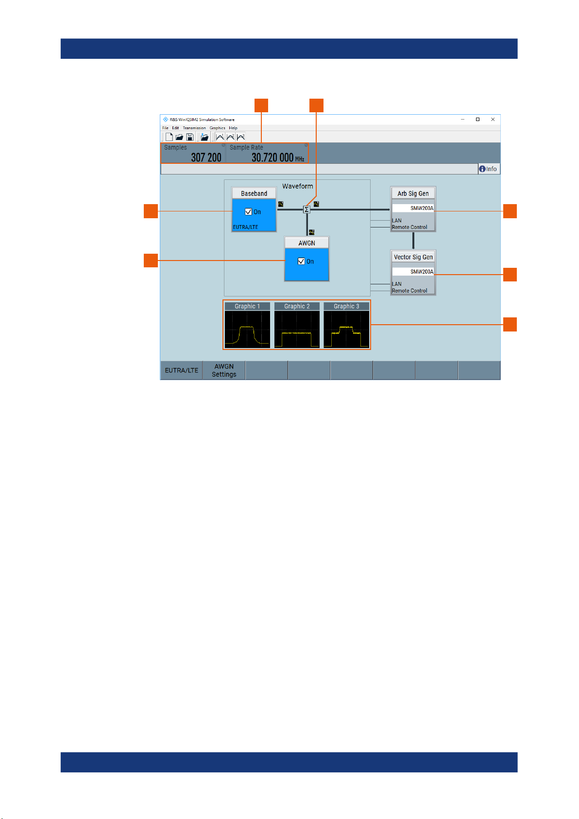
Figure 1-1: R&S WinIQSIM2 application window with signal flow
1 = noise signal
2 = digital waveform signal
3 = main parameters of the waveform signal
4 = superimposed signal
5 = connected arbitrary waveform signal generator
6 = connected vector signal generator
7 = graphical display of the digital waveform, noise and superimposed signals
5
6
7
The application window displays the signal generation in a block diagram. It indicates
the current state of the functional blocks and allows you to display the current signal
configuration graphically. The signal flow follows the logical left-to-right direction. The
status bar above the block diagram shows the main characteristics of the signal. Thus
you can see the status of signal configuration and active interfering components at a
glance.
Comprehensive graphic display modes in time and frequency domain allow simulation
and analysis of characteristics of digital communication systems. You can display for
example i(t) and q(t), vector diagrams or spectrums.
You can configure the signal directly in the block diagram. R&S WinIQSIM2 offers intuitive and straight forward operation with a high degree of self-explanation due to the
logically structured signal flow, dialogs and menus.
Related descriptions
The embedded context-sensitive help systems provide the help content related to the
element you are currently interacting with. The table of contents, the index and the find
9User Manual 1177.5533.02 ─ 07
Page 10

R&S®WinIQSIM2
TM
Welcome to the Simulation Software R&S WinIQSIM2
functions supports you in finding the information if you are using the documentation in
pdf format or printable form. In particular in printed documents, you can find it helpful to
use this section and get familiar with the structure of this description.
The description follows the procedure as you likely configure a new signal generation
task. It starts with configuring the baseband source, describes how you can assign a
noise or interferer signal and validate the signal with the graphics display. Setting up an
instrument and transmitting the waveform file to the destination instrument complete
the process description.
Finally, the description deals with general functions of R&S WinIQSIM2, information
about remote control, like network connection and remote control commands, as well
as error messages and troubleshooting.
1.1 Key Features
Outstanding features of R&S WinIQSIM2 are:
●
Generation of all important digital communication standard signals
●
Generation of custom digital signals, like single, multi-carrier CW or multi-segment
waveforms
●
Generation of noise signals with selectable bandwidth
●
Importing I/Q samples for additional filtering or superimposing
●
Comprehensive graphic display modes
●
Intuitive operation via the block diagram
●
Signal transmission to instruments via GPIB, USB, LAN, or file transfer via USB
stick
●
Direct control of instruments via LAN (remote desktop)
Related Rohde
& Schwarz Instruments
For a detailed specification, refer to the data sheet.
1.2 Related Rohde & Schwarz Instruments
Waveform signals computed by R&S WinIQSIM2 can be loaded onto and processed
by Rohde & Schwarz instruments as listed below. These instruments are equipped with
an ARB generator or provide a waveform memory playback.
Generation of waveforms for ARB generators
●
R&S SMW
●
R&S SMM
●
R&S SMBVB
●
R&S SMCVB
●
R&S SGT
●
R&S SMBV
10User Manual 1177.5533.02 ─ 07
Page 11

R&S®WinIQSIM2
TM
●
R&S SMU
●
R&S SMJ
●
R&S AMU
●
R&S AFQ
●
R&S EX-IQ-BOX (waveform generation without data transfer)
●
R&S BTC
●
R&S SFU
●
R&S CMW (R&S CMW100 and R&S CMW500)
Control of vector signal generators
The following vector signal generators can be used for generation of radio frequency
(RF) signals. Moreover, these vector signal generators can be controlled by
R&S WinIQSIM2:
●
R&S SMW
●
R&S SMM
●
R&S SMBVB
●
R&S SMCVB
●
R&S SGT
●
R&S SMBV
●
R&S SMU
●
R&S SMJ
Welcome to the Simulation Software R&S WinIQSIM2
Documentation Overview
1.3 Documentation Overview
This section provides an overview of the R&S WinIQSIM2 user documentation. Unless
specified otherwise, you find the documents on the R&S WinIQSIM2 product page at:
www.rohde-schwarz.com/manual/winiqsim2
1.3.1 Quick Start Guide Manual
Introduces the R&S WinIQSIM2 and describes how to set up and start working with the
product. Includes basic operations, typical measurement examples, and general information, e.g. safety instructions, etc. A printed version is delivered with the instrument.
1.3.2 Operating Manual and Help
Separate manuals for the base unit and the software options are provided for download:
●
Base unit manual
Contains the description of all instrument modes and functions. It also provides an
introduction to remote control, a complete description of the remote control com-
11User Manual 1177.5533.02 ─ 07
Page 12

R&S®WinIQSIM2
1.3.3 Service Manual
TM
mands with programming examples, and information on maintenance, instrument
interfaces and error messages. Includes the contents of the getting started manual.
●
Software option manual
Contains the description of the specific functions of an option. Basic information on
operating the R&S WinIQSIM2 is not included.
The contents of the user manuals are available as help in the R&S WinIQSIM2. The
help offers quick, context-sensitive access to the complete information for the base unit
and the software options.
All user manuals are also available for download or for immediate display on the Internet.
Describes the performance test for checking the rated specifications, module replacement and repair, firmware update, troubleshooting and fault elimination, and contains
mechanical drawings and spare part lists.
Welcome to the Simulation Software R&S WinIQSIM2
Documentation Overview
The service manual is available for registered users on the global Rohde & Schwarz
information system (GLORIS, https://gloris.rohde-schwarz.com).
1.3.4 Instrument Security Procedures
Deals with security issues when working with the R&S WinIQSIM2 in secure areas. It is
available for download on the Internet.
1.3.5 Basic Safety Instructions
Contains safety instructions, operating conditions and further important information.
The printed document is delivered with the instrument.
1.3.6 Data Sheets and Brochures
The data sheet contains the technical specifications of the R&S WinIQSIM2. It also
lists the options and their order numbers and optional accessories.
The brochure provides an overview of the instrument and deals with the specific characteristics.
See www.rohde-schwarz.com/brochure-datasheet/winiqsim2
1.3.7 Release Notes and Open Source Acknowledgment (OSA)
The release notes list new features, improvements and known issues of the current
software version, and describe the software installation.
12User Manual 1177.5533.02 ─ 07
Page 13

R&S®WinIQSIM2
1.3.8 Application Notes, Application Cards, White Papers, etc.
1.4 Typographical Conventions
TM
Welcome to the Simulation Software R&S WinIQSIM2
Notes on Screenshots
The open source acknowledgment document provides verbatim license texts of the
used open source software.
See www.rohde-schwarz.com/software/winiqsim2
These documents deal with special applications or background information on particular topics.
See www.rohde-schwarz.com/application/winiqsim2.
The following text markers are used throughout this documentation:
Convention Description
"Graphical user interface elements"
[Keys] Key and knob names are enclosed by square brackets.
Filenames, commands,
program code
Input Input to be entered by the user is displayed in italics.
Links Links that you can click are displayed in blue font.
"References" References to other parts of the documentation are enclosed by quota-
All names of graphical user interface elements on the screen, such as
dialog boxes, menus, options, buttons, and softkeys are enclosed by
quotation marks.
Filenames, commands, coding samples and screen output are distinguished by their font.
tion marks.
1.5 Notes on Screenshots
When describing the functions of the product, we use sample screenshots. These
screenshots are meant to illustrate as many as possible of the provided functions and
possible interdependencies between parameters. The shown values may not represent
realistic usage scenarios.
The screenshots usually show a fully equipped product, that is: with all options installed. Thus, some functions shown in the screenshots may not be available in your particular product configuration.
13User Manual 1177.5533.02 ─ 07
Page 14

R&S®WinIQSIM2
2 Getting Started
2.1 Installing the R&S WinIQSIM2 Software
TM
Getting Started
Installing the R&S WinIQSIM2 Software
This section describes the basic steps to be taken when starting up R&S WinIQSIM2
the first time.
● Installing the R&S WinIQSIM2 Software.................................................................14
● Starting R&S WinIQSIM2........................................................................................16
● Trying Out R&S WinIQSIM2....................................................................................17
● Overview of R&S WinIQSIM2................................................................................. 32
● Controlling R&S WinIQSIM2................................................................................... 34
● Getting Information and Help.................................................................................. 42
R&S WinIQSIM2 is a stand-alone, PC-based application that creates waveform files of
digitally modulated signals.
You find the up-to-date version of R&S WinIQSIM2 and the corresponding release
notes describing the improvements and modifications on the product homepage "http://
www.rohde-schwarz.com/product/WinIQSIM2.html > Download > Software".
Software and hardware requirements
To install and run R&S WinIQSIM2, the following hardware and software requirements
have to be met:
Table 2-1: Software requirements
Operating system
System type
VISA runtime
library
Options Remarks
Microsoft® Windows 10, version
1607 "Anniversary Edition" and later
●
64-bit operating system
●
x64-based or x86-based processor
●
R&S VISA, IO libraries for
instrument control
●
National Instruments VISA 4.0.
or higher (optional)
●
other VISA runtime library
Any other versions or operating systems are
not supported. The installation process checks
the operating system and aborts the installation if your PC is not compatible.
You can only run the latest WinIQSIM2 software on a 64-bit operating system. 64-bit
installation files have the extension "x64":
WinIQSIM2_v.vv.vvv.vv.x64.exe
VISA driver is bundled with a GPIB (IEC/
IEEE)-bus card from National Instruments (NI)
or Agilent. If none of these cards are used,
there is the option to perform data transmission via TCP/IP connection over LAN.
Drivers can be obtained from R&S or NI
directly.
14User Manual 1177.5533.02 ─ 07
Page 15
R&S®WinIQSIM2
TM
Getting Started
Installing the R&S
Table 2-2: Hardware requirements
AMD / Intel CPU 1 GHz 2 GHz
RAM 1 GB
Display resolution 1024 x 800 pixels ≥ 1024 x 800 pixels
GPIB (IEC/IEEE)bus card
Free HD space 600 MB 2 GB
Minimum requirements Recommended hardware
2 GB
Note: The installation process
checks the RAM size and aborts the
installation if the minimum memory
size is not given.
●
National Instruments
●
Agilent
optional
WinIQSIM2 Software
To install the software
To install the software, perform the following:
●
Administrator rights are required to install and run the program.
●
It is recommended that you uninstall any previous version of R&S WinIQSIM2
before installing the new version (see To uninstall a previous software version).
1. In the windows explorer, execute WinIQSIM2_v.vv.vvv.vv.x64.exe.
<v.vv.vvv.vv.x64> stands for the current version of the 64-bit software as in
Table 2-1.
2. Follow the instructions of the installation wizard.
The setup file installs all software components R&S WinIQSIM2 requires for operation.
Table 2-3: Default file location (software installation for all users)
File type File location File name
User settings and data
(waveforms, save/recall,
etc.)
Program data
%APPDATA%\Rohde-Schwarz\winiqsim2
%PROGRAMFILES(X86)%\Rohde-Schwarz\
WinIQSIM2\xx.x
*.wv, *.savrcl, etc.
WinIQSIM2_Start.cmd
To uninstall a previous software version
To uninstall a previous version, perform the following:
1. In the taskbar, select the "Windows Start" button.
2. Select "Settings > Control Panel > Programs > Programs and Features".
3. In the list of programs, select "R&S WinIQSIM2_v.vv.vvv.vv.x64".
15User Manual 1177.5533.02 ─ 07
Page 16

R&S®WinIQSIM2
TM
Getting Started
4. Remove the program with "Uninstall/Change > Uninstall".
The script file identifies and removes any currently installed items of R&S WinIQSIM2.
2.2 Starting R&S WinIQSIM2
To access R&S WinIQSIM2 easily, create a shortcut to the *.exe file and place it on
the desktop of your computer.
Access:
1. On your computer, perform one of the following:
a) Select "Start > All Programs > R&S WinIQSIM2 > R&S WinIQSIM2 v.vv.vvv.vv"
b) Double-click the shortcut icon on the desktop.
After starting up, the main application window appears.
Starting R&S
WinIQSIM2
Figure 2-1: R&S WinIQSIM2 main application window in initial state
2.
Select "File > New" (or the icon alternatively) to start from an initial state.
16User Manual 1177.5533.02 ─ 07
Page 17

R&S®WinIQSIM2
TM
Getting Started
2.3 Trying Out R&S WinIQSIM2
The following is an example on how to use R&S WinIQSIM2 to generate a single carrier waveform with AWGN and load it in the ARB of an R&S SMW200A .
The workflow includes the following steps:
● Configuring the Instrument......................................................................................17
● Selecting the Instrument......................................................................................... 19
● Generating a Waveform Signal...............................................................................19
● Adding Noise to the Waveform Signal.................................................................... 22
● Visualizing the Waveform Signal.............................................................................23
● Transmitting the Waveform to the R&S SMW200A.................................................30
● Transmitting the Waveform to a File....................................................................... 31
2.3.1 Configuring the Instrument
Before you can transmit a signal to a signal generator, you must configure the destination instrument and the connection between the PC with instrument and R&S WinIQSIM2.
Trying Out R&S
WinIQSIM2
R&S WinIQSIM2 allows you to scan the LAN, GPIB, or USB interfaces for connected
instruments ("Arb Sig Gen or Vector Sig Gen"). Detected instruments are automatically
assigned to the list of "Available Instruments", including the associated information on
the connection.
Alternatively, you can create and configure an instrument manually, as described in "To
add an instrument manually" on page 190.
The general instrument settings affect various functions, e.g. the maximum size of the
waveform file. We recommend that you configure a detected instrument first before
creating the waveform file.
To scan for instruments
1. Connect the instrument to the LAN, e.g. an R&S SMW200A with option R&S SMWB10.
2. Switch on the instrument.
3. In the menu bar of R&S WinIQSIM2, select "File > New" to start the software from
an initial state.
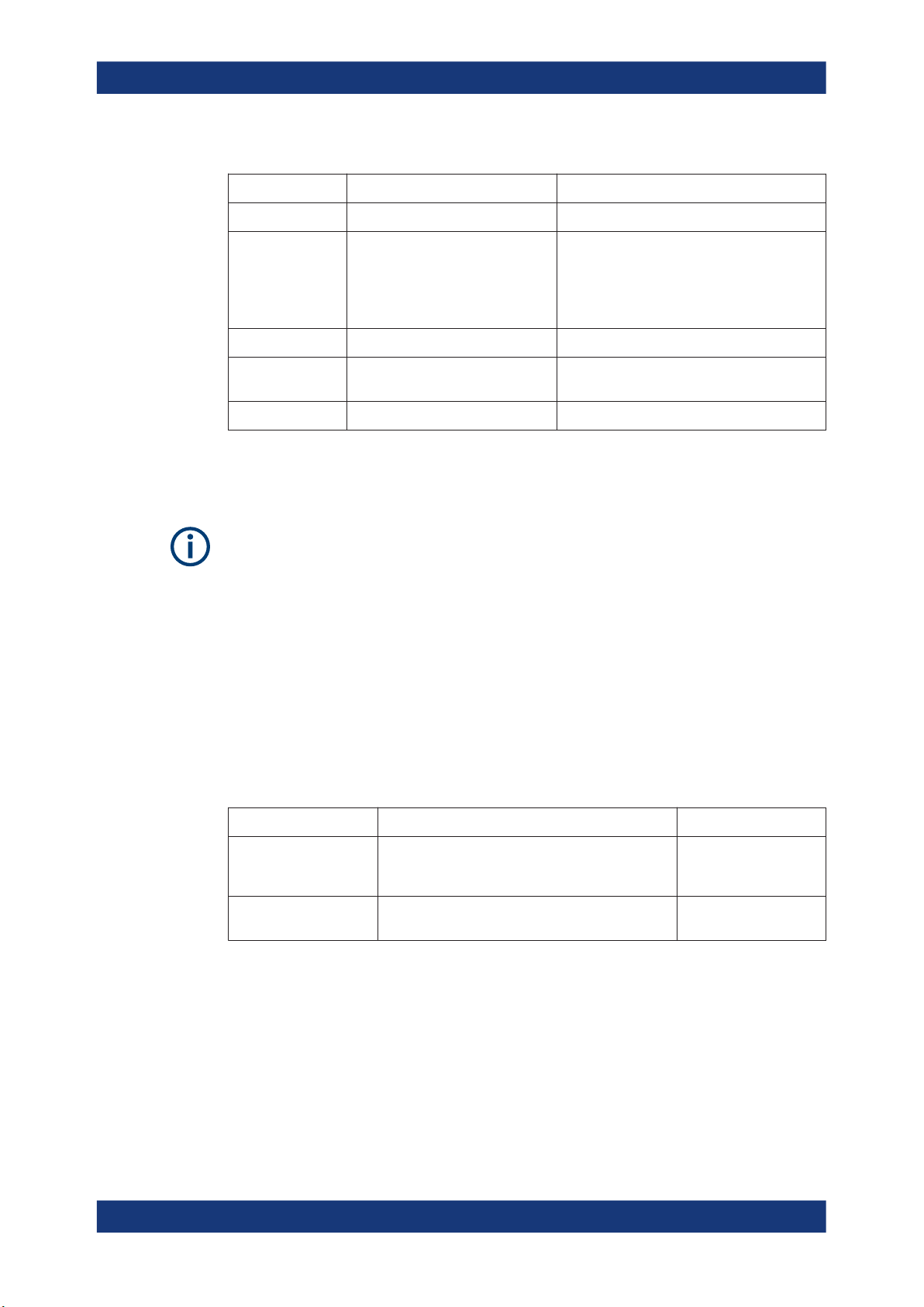
4. In the block diagram, select "Arb Sig Gen > Instruments".
The "Configure Instruments" dialog opens allowing you to perform the following:
● Search for instruments in a network
● Search for instruments in a dedicated subnet of the network
● Search for instruments with USB/GPIB connection to a PC with R&S WinIQ-
SIM2 installed
● Configure detected instruments
17User Manual 1177.5533.02 ─ 07
Page 18
R&S®WinIQSIM2
TM
Getting Started
Trying Out R&S
WinIQSIM2
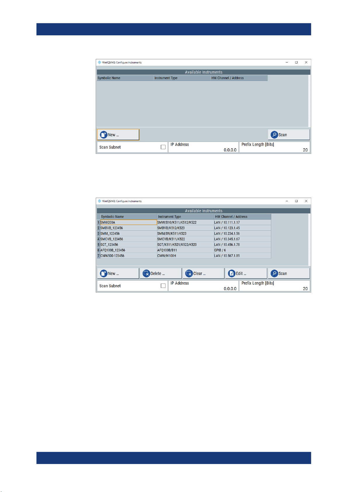
5. Select "Scan" to search for instruments.
All instruments found in the network and instruments connected via the GPIB or
USB interfaces are displayed in the list of "Available Instruments". R&S WinIQSIM2
retrieves all information on connection to the instrument automatically.
Note: R&S WinIQSIM2 does not clear the list of "Available Instruments" before a
scan. Any instruments found during a scan are added to the list.
6. If you found your R&S SMW200A in the list, close the dialog.
To scan a subnet of the network
To accelerate the scan of the network you can specify subnet parameters and an IP
address of an instrument, that you know of.
1. Open the "Configure Instruments" dialog as described in "To scan for instruments"
on page 17.
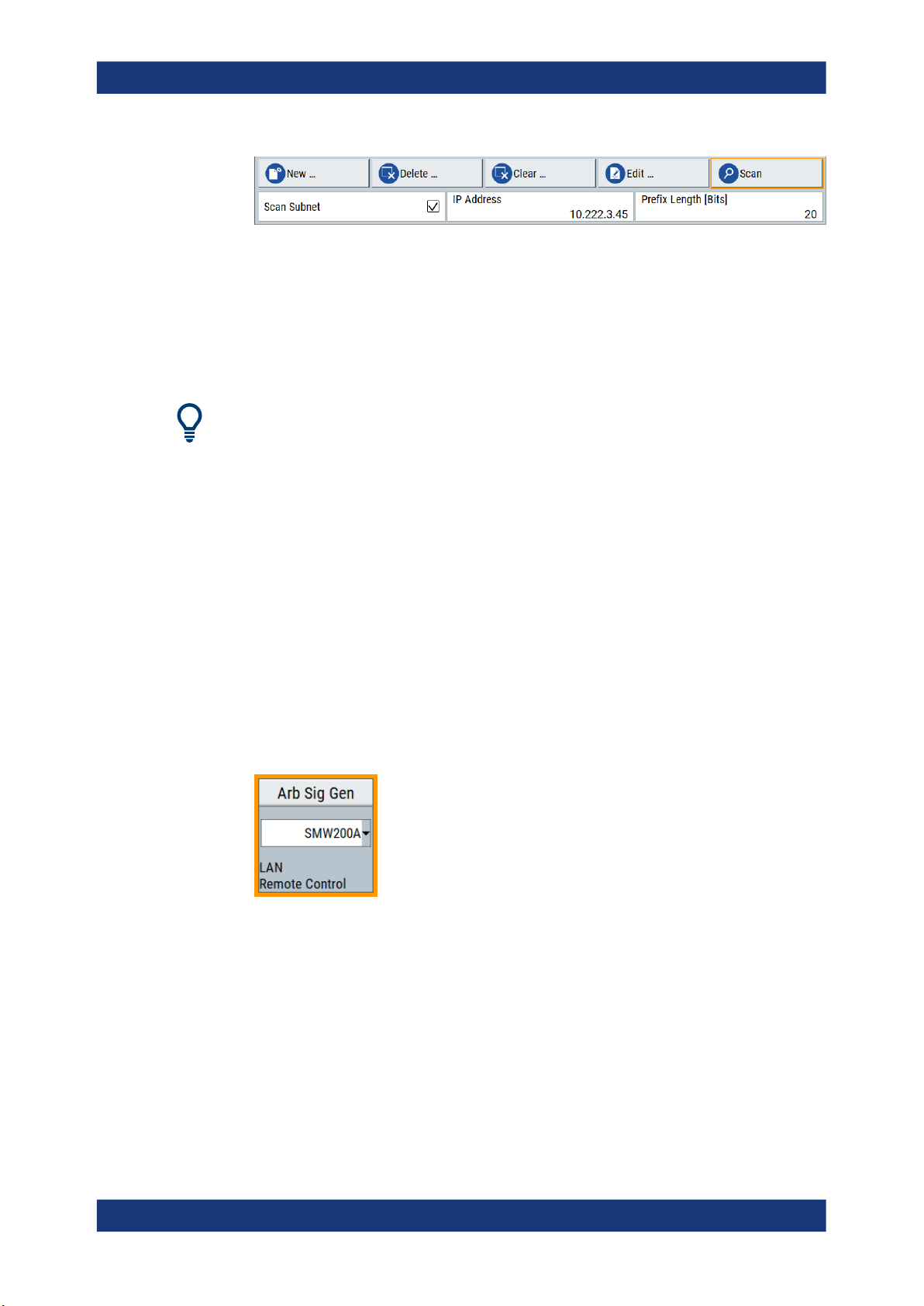
2. Select "Scan Subnet > On".
3. Set the IP address of an instrument within the subnet, e.g. "10.222.3.45".
4. Set the prefix length of the subnet, e.g. "20" bits.
5. Select "Scan".
18User Manual 1177.5533.02 ─ 07
Page 19
R&S®WinIQSIM2
TM
Getting Started
Trying Out R&S
The scan procedure searches for instruments within the subnet, to which the IP
address "10.222.3.45" belongs
To modify the configuration of detected instruments
You can configure search results of the list and modify the configuration of detected
instruments, see Chapter 6.2, "Configure Instruments Settings", on page 182.
Troubleshooting non-detected instruments after scan
If the instrument you want to work with is not listed, check if the following prerequisites
are fulfilled, and scan for the instrument again:
●
Is the instrument switched on?
●
Is the instrument accessible via LAN, GPIB, or USB?
●
Is the firewall of the instruments' operating system deactivated?
WinIQSIM2
2.3.2 Selecting the Instrument
Before you can create a waveform, you must select and configure any instrument in
advance (see also Chapter 2.3.1, "Configuring the Instrument", on page 17).
For the calculation, it is not imperative that a real instrument is connected. You can
also create a waveform based on a manually configured instrument (offline).
► In the instrument selection list of the "Arb SigGen" block, select e.g. "SMW200A".
The R&S SMW200A is selected as the ARB signal generator used to create the
waveform signal.
2.3.3 Generating a Waveform Signal
The example task is to configure a digital signal in accordance with the EUTRA/LTE
standard. It introduces the way to access the settings and the configuration principle
common for digital standards, and the R&S WinIQSIM2 software.
19User Manual 1177.5533.02 ─ 07
Page 20

R&S®WinIQSIM2
TM
Getting Started
Trying Out R&S
WinIQSIM2
We use one of the provided EUTRA test models (E-TM), to show how to configure and
generate a test signal.
1. In the menu bar, select "File > new" to start from an initial state.
R&S WinIQSIM2 sets all settings to default, except selected instruments in the
"ARB Sig Gen" and "Vector Sig Gen" blocks.
2. In the block diagram, select "Baseband > EUTRA/LTE".
The "EUTRA/LTE" settings dialog contains the parameters to configure the waveform signal.
3. In the "General" tab, select "Link Direction > Downlink (OFDMA)".
4. Select "Test Models > E-TM1_1__10MHz".
20User Manual 1177.5533.02 ─ 07
Page 21

R&S®WinIQSIM2
TM
Getting Started
Trying Out R&S
WinIQSIM2
5. Confirm with "Select".
The "Test Models" is a function for quick selection and settings adjustment according to one of the various EUTRA test models (E-TM). A standard "File Select" function enables you to select form files with predefined settings.
The dialog closes automatically and the user interface confirms the name of the
selected file.
6. Select "General DL Settings" to have a look at the channel bandwidth and the
occupied bandwidth of the selected signal.
Figure 2-2: Test model E-TM1_1_10MHz bandwidth parameters
1 = "Channel Bandwidth > 10 MHz"
2 = "Occupied Bandwidth > 9.015 MHz"
The selected test model operates with a channel bandwidth of 10 MHz. The signal
occupies 9.015 MHz.
1
2
7. Close the "General DL Settings" dialog.
21User Manual 1177.5533.02 ─ 07
Page 22

R&S®WinIQSIM2
TM
Getting Started
Trying Out R&S
WinIQSIM2
8. In the "General" tab, select "State > On".
R&S WinIQSIM2 calculates the EUTRA/LTE test signal with the selected channel
bandwidth. It displays the characteristic signal parameters, i.e. the number of
"Samples" and the used "Sample Rate" in the status bar of the main window.
2.3.4 Adding Noise to the Waveform Signal
In R&S WinIQSIM2, you can also superimpose the waveform with noise.
In the example, we generate an average white Gaussian noise (AWGN) signal that is
to be superimposed with the interference-free LTE signal. The minimum noise to system bandwidth ratio is two.
1. In the block diagram, select "AWGN".
The "AWGN Settings" dialog contains the parameters for configuring additive white
Gaussian noise, noise level or CW interfering.
2. In the "General" tab, select "Mode > Additive Noise".
3. Set "System Bandwidth > 10 MHz".
4. Enter "Min. Noise/System Bandwidth Ratio > 2".
5. In the "Noise Power / Output Results" tab, enter "Bit Rate > 270.833333 kbps".
22User Manual 1177.5533.02 ─ 07
Page 23

R&S®WinIQSIM2
TM
Getting Started
6. Enter "Carrier/Noise Ratio > 30 dB".
7. In the "General" tab, select state "On".
R&S WinIQSIM2 generates the noise signal.
2.3.5 Visualizing the Waveform Signal
Trying Out R&S
WinIQSIM2
It is often useful to verify a generated waveform before storing or transmission. This
example shows you how to configure the display function of the R&S WinIQSIM2, and
how to view the signals in particular, both the baseband and the AWGN, and the superimposed signal. The example uses the waveform generated as described in Chap-
ter 2.3.3, "Generating a Waveform Signal", on page 19, and the AWGN signal of Chap-
ter 2.3.4, "Adding Noise to the Waveform Signal", on page 22.
The graphics panel is an important tool for checking the signal configuration. In this
panel, you can display the generated I/Q signal as I/Q diagram, and derived representations thereof like the vector diagram or the signal spectrum. For more information,
see Chapter 5, "Displaying Simulated Waveforms Graphically", on page 155.
To display the baseband waveform signal
1. In the menu bar of the main window, select "Graphics > Graphic 1 > Graphic 1
(Preview Only)".
R&S WinIQSIM2 indicates the graphics preview in the block diagram.
A small icon assigned directly to the signal line indicates the shown waveform.
To access the graphic settings, perform one of the following:
a) Double-click the small graphics display.
23User Manual 1177.5533.02 ─ 07
Page 24
R&S®WinIQSIM2
TM
Getting Started
Trying Out R&S
WinIQSIM2
b) In the menu bar, select "Graphics > Graphic 1 > Graphic 1 (Complete)".
The "Graphic 1" settings dialog opens displaying "Viewport" and "Options:" settings
to configure the operating range of the waveform and specify the signal that you
want to monitor.
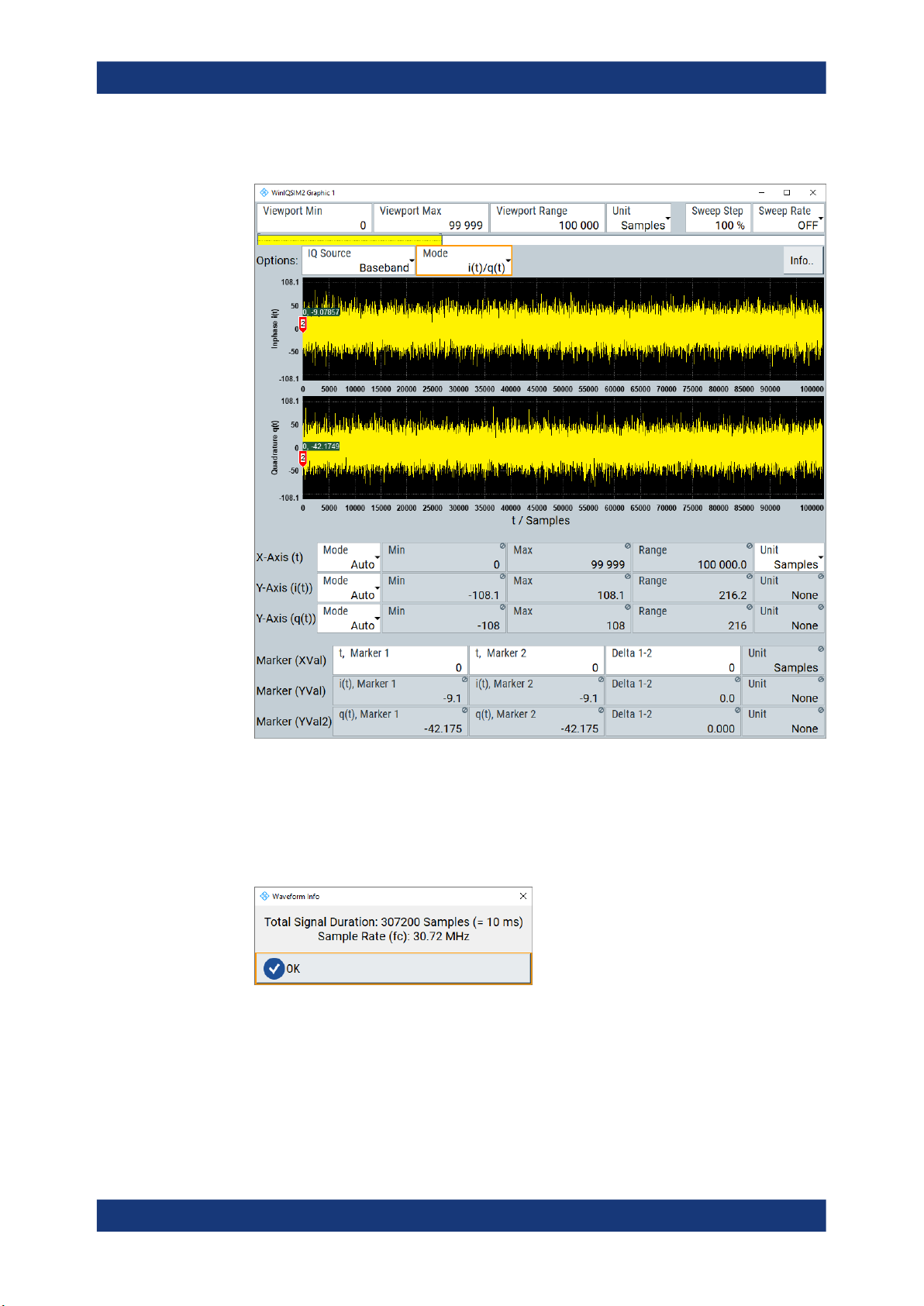
2. To configure the waveform operating range, specify the "Viewport" parameters.
3. To check signal duration and sample rate, click the "Info.." button.
4. To configure the I/Q parameters, try out the following:
a) Select "IQ Source > Baseband".
b) Select "Mode > FFT Magnitude".
24User Manual 1177.5533.02 ─ 07
Page 25
R&S®WinIQSIM2
TM
Getting Started
Trying Out R&S
WinIQSIM2
c) Select "FftLen > 2048 (2^11)".
The power spectrum displays the frequency versus the amplitude of the baseband
signal of the waveform.
For related settings, see Chapter 5, "Displaying Simulated Waveforms Graphically",
on page 155.
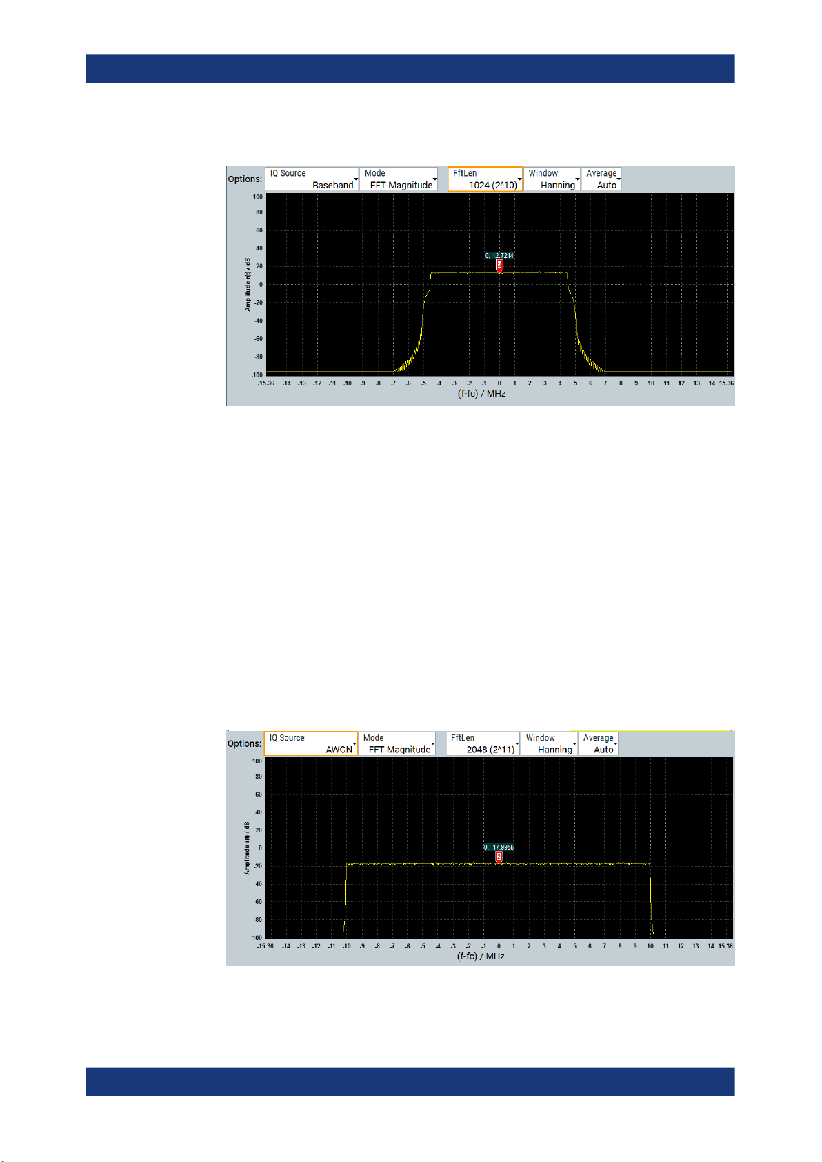
To display the AWGN signal
In this example, we use the second graphic function to display the AWGN signal. Perform the following steps:
1. In the menu bar of the main window, select "Graphics > Graphic 2 > Graphic 2
(Complete)".
2. In the "Graphic" dialog, select "IQ Source > AWGN".
3. Select "Mode > FFT Magnitude".
4. Select "Len > 2048 (2^11)".
The power spectrum displays the generated additive white gaussian noise signal.
25User Manual 1177.5533.02 ─ 07
Page 26
R&S®WinIQSIM2
TM
Getting Started
Trying Out R&S
WinIQSIM2
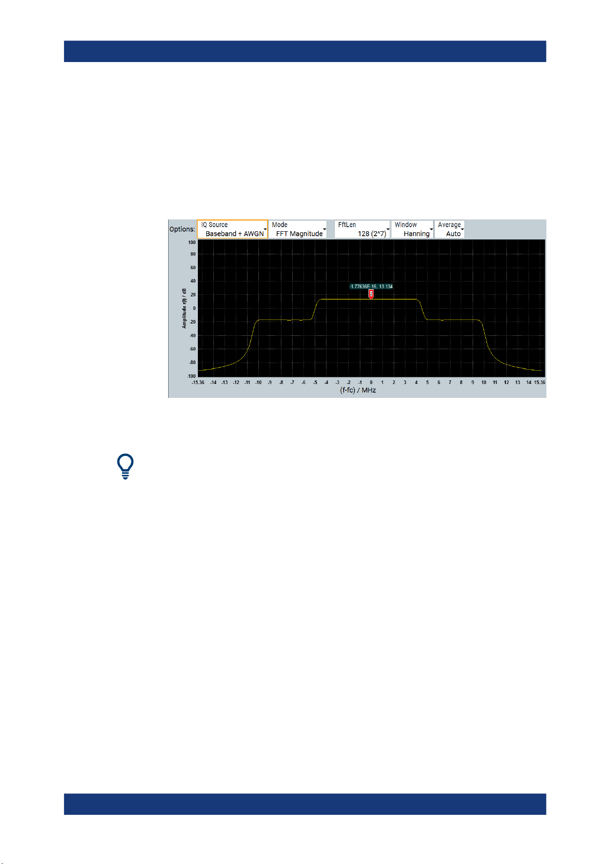
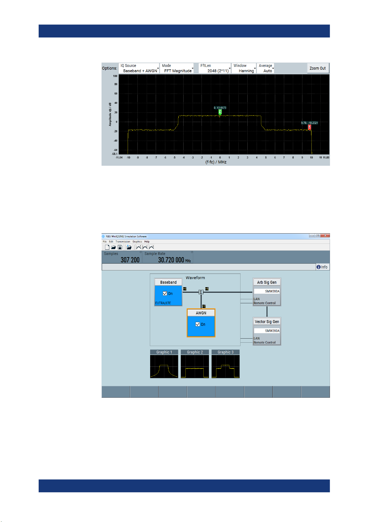
To display the baseband signal superimposed with AWGN
1. In the menu bar of the main window, select "Graphics > Graphic 3 > Graphic 3
(Complete)".
2. Select "IQ Source > Baseband + AWGN".
3. Select "Mode > FFT Magnitude".
4. Select "Len > 2048 (2^11)".
The power spectrum displays the waveform derived from the baseband signal
superimposed with the AWGN signal.
To retrieve more information, zoom in the spectrum and place the markers to the positions to measure the corresponding values (see To zoom a particular area of the wave-
form).
Using markers to analyze the signal
Using the markers you can determine particular readings of the signals, e.g. to verify
the settings directly in the graph. You can position the markers in the diagram to find
out the appropriate values.
In the following examples, we set the markers to determine the occupied bandwidth of
the baseband waveform, and the carrier/noise ratio.
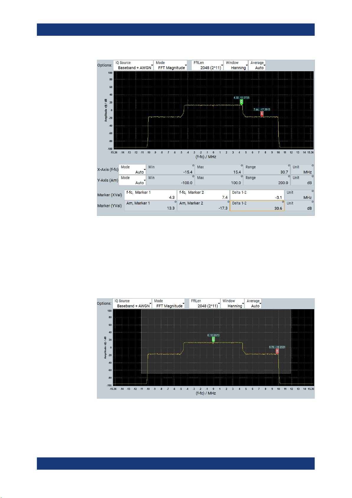
To determine the occupied bandwidth of the baseband signal
1. Open the "Graphics 3" dialog.
2. In the diagram, drag the first marker to the left:
a) Left-click the first marker.
b) Keep the mouse key pressed.
R&S WinIQSIM2 denotes the current X-axis position by a colored line.
3. Drag and drop the marker to the start position of baseband signal (on-time).
26User Manual 1177.5533.02 ─ 07
Page 27

R&S®WinIQSIM2
TM
Trying Out R&S WinIQSIM2
4. Accordingly, move the second marker to the end position.
Getting Started
You can see the current X and Y-axis positions of the markers in the diagram, or in
the "Marker" fields in the lower section of the dialog. The calculated "Delta 1-2" frequency value reflects the occupied bandwidth of the EUTRA/LTE signal approximately, see Generating a Waveform Signal, step 6.
To determine the carrier to noise ratio
1. Open the "Graphics 3" dialog.
2. In the diagram, left-click and hold the first marker.
3. Drag and drop "Marker 1" to the top level of the noise signal.
4. Accordingly, move the second marker to the top level of the baseband waveform
signal.
27User Manual 1177.5533.02 ─ 07
Page 28
R&S®WinIQSIM2
TM
Getting Started
Trying Out R&S
WinIQSIM2
R&S WinIQSIM2 determines the carrier/noise ratio of approximately 30 dB based
on the markers amplitude values.
To zoom a particular area of the waveform
To retrieve more information, you can enlarge any section of the graph and thus visualize particular values of the signal in detail.
1. Left-click and hold the upper left corner of the section you want to zoom.
2. Draw the zoom rectangle.
A dotted rectangular frame denotes the marked area.
3. Release the mouse button.
28User Manual 1177.5533.02 ─ 07
Page 29
R&S®WinIQSIM2
TM
Getting Started
Trying Out R&S
WinIQSIM2
R&S WinIQSIM2 enlarges the selected section. Now you can analyze the signal
trace in more detail visually.
4. To return to the initial size, select "Zoom Out".
To display the graphics in the main window
► Close all graphics dialogs.
R&S WinIQSIM2 shows the small graphics preview of all active diagrams. "Graphic
1" displays the baseband signal, in "Graphic 2" you can see the AWGN signal, and
in "Graphic 3" the baseband signal interfered with noise.
29User Manual 1177.5533.02 ─ 07
Page 30
R&S®WinIQSIM2
TM
Getting Started
Trying Out R&S
2.3.6 Transmitting the Waveform to the R&S SMW200A
Transferring the waveform file to the signal generator, requires that the connection
between R&S WinIQSIM2 and the R&S SMW200A is established.
You can see the connection at a glance in the block diagram denoted by the two thin
control lines, see Chapter 2.5.1.4, "Block Diagram", on page 37.
If the lines are crossed, establish the connection as described in Chapter 2.3.1, "Con-
figuring the Instrument", on page 17 and Chapter 2.3.2, "Selecting the Instrument",
on page 19.
In addition, the following requirements must be met:
●
Enabled file transfer via LAN and the used interface protocol
●
Enabled write permission on the instrument's file system
For more information on security settings, see the user manual of the instrument.
To transmit the generated waveform to the R&S SMW200A
WinIQSIM2
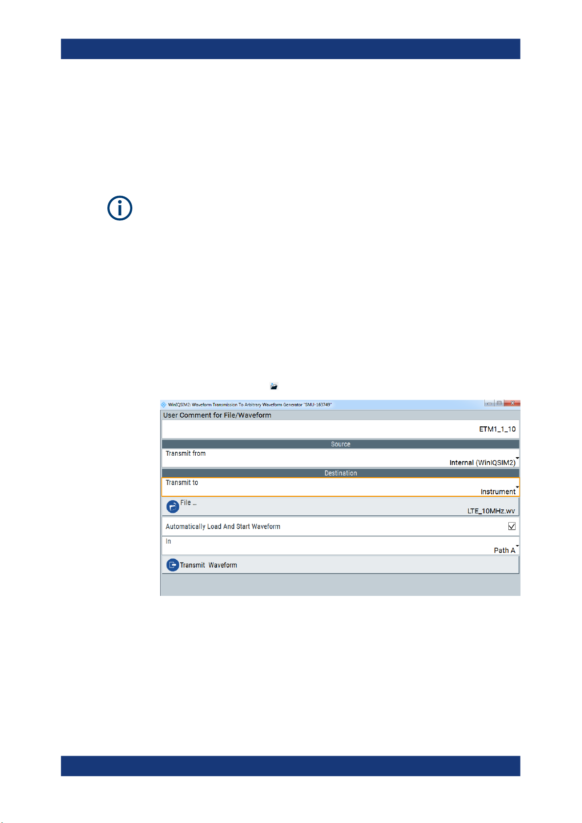
1. To configure the transmission, perform one of the following:
a) In the menu bar, select "Transmission > Transmit".
b)
In the tool bar, select .
The "Waveform Transmission To Arbitrary Signal Generator" dialog opens.
2. Select "Source > Internal (WinIQSIM2)"
R&S WinIQSIM2 selects the last generated waveform data automatically.
3. Select "Destination > Transmit To > Instrument".
4. Select "File" to determine the file name and directory for storing on the instrument.
a) Select/create the destination directory on the instrument.
b) Enter the "File Name".
30User Manual 1177.5533.02 ─ 07
Page 31

R&S®WinIQSIM2
TM
Getting Started
c) Confirm with "Ok".
To activate ARB signal generation at the R&S SMW200A
The waveform is ready for transmission to the instrument as described in "To transmit
the generated waveform to the R&S SMW200A" on page 30.
1. Open the dialog "Waveform Transmission To Arbitrary Signal Generator".
2. Select the required baseband path, for example "Path A".
3. Add a comment to the waveform.
4. Select "Transmit" to start the transmission.
R&S WinIQSIM2 transmits the waveform file to selected folder of the R&S
SMW200A. After successful transmission, the R&S SMW200A loads the file, enables the ARB and plays the transmitted waveform, and automatically provides the
waveform signal at the I/Q modulator outputs.
2.3.7 Transmitting the Waveform to a File
Trying Out R&S
WinIQSIM2
When transmitting the waveform signal to a file, R&S WinIQSIM2 basically saves the
signal information in a file.
To save the generated waveform file
1.
In the tool bar, select .
The "Waveform Transmission To Arbitrary Signal Generator" dialog opens.
2. Add a comment to the waveform.
3. Confirm with [Enter].
4. Select "Source > Internal (WinIQSIM2)"
R&S WinIQSIM2 selects the last generated waveform data automatically.
5. Select "Destination > File".
6. Select "File" to determine the file name and directory for storing the waveform.
31User Manual 1177.5533.02 ─ 07
Page 32

R&S®WinIQSIM2
TM
Getting Started
a) Select/create the destination directory.
b) Enter the "File Name".
c) Confirm with "Save".
7. Select "Transmit Waveform".
R&S WinIQSIM2 saves the waveform file with file extension *.wv in the specified
directory on your computer.
2.4 Overview of R&S WinIQSIM2
This section helps you to get familiar with R&S WinIQSIM2. It provides an introduction
to the general concept of the software, including the description of the main blocks in
the signal generation flow.
● Brief Introduction to the Concept of R&S WinIQSIM2.............................................32
● Possible Ways to Operate R&S WinIQSIM2...........................................................32
● Signal Flow at a Glance.......................................................................................... 33
● Baseband Block...................................................................................................... 33
● AWGN Block (Additional White Gaussian Noise)................................................... 34
● Arb Sig Gen and Vector Sig Gen Blocks (Connected Instruments)........................34
Overview of R&S
WinIQSIM2
2.4.1 Brief Introduction to the Concept of R&S WinIQSIM2
The signal generation software comprises all the functionalities required for creating
waveform files of digitally modulated baseband signals. It provides almost all standardcompliant digital signals, user-definable signals with selectable modulation parameters
and multi carrier signals.
The graphical user interface provides intuitive operation via a block diagram, representing the core functionalities in blocks. You can control the entire process of the signal configuration via the block diagram. At a glance, you can see the status of signal
configuration, active interfering signals, the signal flow and connected instruments. In
addition, R&S WinIQSIM2 shows the signals graphically.
2.4.2 Possible Ways to Operate R&S WinIQSIM2
This chapter provides an overview on how to work with R&S WinIQSIM2 and describes
the manual operation of the software and also the alternative ways of operation.
There are two ways to operate R&S WinIQSIM2:
●
Manual operation:
Run the software on your PC and use the mouse and/or keyboard.
●
Remote control:
A remote control program either installed on the same or another computer, controls R&S WinIQSIM2, see Chapter 2.5.3, "Remote Control", on page 42.
32User Manual 1177.5533.02 ─ 07
Page 33

R&S®WinIQSIM2
TM
Getting Started
With remote control, you can create programs to automate repeating settings, tests
and measurements.
This way of operation is described Chapter 10, "Automation of R&S WinIQSIM2",
on page 224.
Tip: As a special function, R&S WinIQSIM2 provides SCPI recording. Using this
function, you can record and save the settings of your configuration for later reuse.
SCPI recording is accessed via the context-sensitive menu.
2.4.3 Signal Flow at a Glance
The framed area symbolizes R&S WinIQSIM2 as one unit. It shows the blocks for generation of the baseband and interfering signals, and the signal flow to the peripheral
signal generators.
2 3
Overview of R&S
WinIQSIM2
1
7 6 5
Figure 2-3: R&S WinIQSIM2 signal flow
1, 6 = noise signal flow and signal shape
2, 7 = digital waveform signal flow and signal shape
3, 5 = signal flow of digital waveform and superimposed noise and signal shape
4 = signal flow of ARB signal from waveform data
2.4.4 Baseband Block
4
The "Baseband" block represents the source of the baseband signals.
This functional block is the access point to:
●
The internal baseband generator
33User Manual 1177.5533.02 ─ 07
Page 34

R&S®WinIQSIM2
TM
Getting Started
Controlling R&S
With the baseband generator, you can create a user-defined signal ("Custom Digital Modulation"), including MCCW signal generation and "Import IQ Data".
●
The available digital standards
Generation of digital signals in accordance with the supported standards require
the corresponding R&S WinIQSIM2 digital standard options installed on the instrument.
WinIQSIM2
2.4.5 AWGN Block (Additional White Gaussian Noise)
The "AWGN" block controls the noise generator (AWGN).
You can create a white noise signal ("Additive White Gaussian Noise"), or a sinusoidal
signal ("CW Interferer") with adjustable frequency offset, and superimpose this noise
signal with the baseband signal. Alternatively, you can generate a pure noise signal
("Noise only").
2.4.6 Arb Sig Gen and Vector Sig Gen Blocks (Connected Instruments)
These blocks represent instruments that can process the waveforms created by
R&S WinIQSIM2. You can configure a remote connection to an instrument in the network, transfer the created waveform file directly and even activate the signal generation on the instrument. In addition, you can scan for connected instruments in the network.
R&S WinIQSIM2 distinguishes two types of generators:
●
"Arb Sig Gen", the arbitrary waveform generators for generating the I/Q baseband
signal.
●
"Vector Sig Gen", the vector signal generators for modulating the I/Q signal to RF
via a local oscillator (LO) and an I/Q modulator.
Both generator types can be integrated in a single instrument, as, e.g., in the
R&S SMW.
But there are also instruments that provide only one component, such as the I/Q modulation generator R&S AFQ or the R&S SGT vector RF source.
R&S WinIQSIM2 assigns detected or manually configured instruments according to
their functionality automatically to respective signal generator block. The instrument
selection fields of the blocks provide all available instruments listed under their symbolic name.
2.5 Controlling R&S WinIQSIM2
This section provides an overview on how to work with R&S WinIQSIM2. It describes
what kind of information is displayed in the diagram area, how to operate R&S WinIQSIM2 manually or in remote control mode, and how to use the online help.
34User Manual 1177.5533.02 ─ 07
Page 35

R&S®WinIQSIM2
2.5.1 Understanding the Display Information
TM
Getting Started
Controlling R&S WinIQSIM2
The application window shows all main settings and control elements of R&S WinIQSIM2. All menus and dialogs use known elements, like, for example, selection lists,
icons, check boxes, and entry fields.
1 2 3
4
5
6
7
Figure 2-4: R&S WinIQSIM2 main application window
1 = Title bar
2 = Menu Bar / Toolbar, page 35
3 = Menu Bar / Toolbar, page 35
4 = Status Bar, page 37
5 = Info Line, page 37
6 = Block Diagram, page 37
7 = Taskbar, page 39
The following sections explain the labeled operation areas in detail.
2.5.1.1 Menu Bar / Toolbar
1
2 3 4 5
Figure 2-5: R&S
WinIQSIM2 menu bar and toolbar
35User Manual 1177.5533.02 ─ 07
Page 36

R&S®WinIQSIM2
TM
Getting Started
Controlling R&S WinIQSIM2
1 = New
2 = Open
3 = Save
4 = Transmit
5 = Graphics
The toolbar contains the most commonly used general functions of the application. The
toolbar icons provide quick and easy access with the mouse pointer. Alternatively, you
can also find these functions in the menus or you can use keyboard shortcuts to execute a function. For an overview, see Table 2-4.
Table 2-4: Menu bar entries / toolbar icons / keyboard shortcuts
Legend Toolbar Menu bar Shortcut Description
1 "File > New" ALT+F > N Resets R&S WinIQSIM2 to default.
2 "File > Open" ALT+F > O Loads an existing configuration file, containing
specific settings of a configured application. The
file extension is predefined (*.savrcl).
3 "File > Save" ALT+F > S Saves all settings to the current configuration to
an existing file.
- - "File > Save as" ALT+F > N Saves the complete settings to the current configuration to a new file (*.savrcl).
- - "File > Setup > Software
Options"
- - "File > Setup > Temporary
Files"
- - "File > Setup > Remote" - Provides access for configuring the remote con-
- - "File > Setup > Undo/Redo" - Erases the last change done (undo)., or reverses
- - "File > Exit" ALT+F > X Terminates R&S WinIQSIM2.
4 "Transmission > Instruments" ALT+T > I Opens a list of available instruments.
- - "Transmission > Transmit" ALT+T > T Opens a dialog for configuring file transmission to
5 "Graphics 1(2,3) > Graphics
1/2/3 (Preview only)"
ALT+F > P Displays the current software version and
options.
ALT+F > P Opens a dialog where you can define the location
for temporary files.
trol interface.
the undo (redo).
The current configuration settings are saved and
restored when you restart the program.
an ARB instrument.
ALT+G > 1... > 1...
(toggle)
Displays a small graphics preview in the block
diagram.
- - "Graphics 1/2/3 > Graphics
1/2/3 (Complete)"
- - "Help > Contents" ALT+H > C Opens the R&S WinIQSIM2 online help.
ALT+G > 1 > 1 (toggle)
Opens the dialog for graphical display.
36User Manual 1177.5533.02 ─ 07
Page 37

R&S®WinIQSIM2
TM
Getting Started
Controlling R&S WinIQSIM2
Legend Toolbar Menu bar Shortcut Description
- - "Help > Index" ALT+H > C Shows the index of the online help.
- - "Help > About" ALT+H > A Displays information on the software version.
2.5.1.2 Status Bar
The status bar displays the main characteristics of the active signal, like samples or
symbols and data rates.
Samples
Displays the number of samples, respectively the number of symbols over sampling
factor, depending on the signal.
Sample Rate
Displays the rate at which the samples are sent, depending on the signal in samples/s
or symbols over sampling factor.
2.5.1.3 Info Line
The info line shows brief status information and error messages. It appears above the
block diagram, when an event generates a message. For information on the error messages and warnings, refer to Chapter 12, "Troubleshooting and Error Messages",
on page 393.
You can also access an info window with detailed information on all messages in a history list. For details, see Chapter 9.2, "Querying Error Messages & Info Key",
on page 220.
2.5.1.4 Block Diagram
The block diagram shows the current configuration and the signal flow in R&S WinIQSIM2 and to the external instruments with the aid of function blocks, connected by signal lines. The following figure displays elements that can appear in the block diagram.
37User Manual 1177.5533.02 ─ 07
Page 38

R&S®WinIQSIM2
TM
Getting Started
Controlling R&S WinIQSIM2
1 2 3 4 5
6 7
8
9
11 1012
1 = Waveform generation section
2 = Baseband block
3 = Graphics indicator
4 = Summation sign
5 = Signal flow arrow
6, 11 = Network control lines (not connected / connected)
7, 10 = Remote control lines (not connected / connected)
8 = ARB signal generator block
9 = Vector signal generator block
12 = Small graphics preview
Legend Item Description
1 Waveform generation section Covers the functional blocks for generating the waveform
and additive white gaussian noise.
2, 8, 9 Functional blocks Represents a basic task in signal generation.
The button provides access to any number of associated
actions to accomplish the task.
The checkbox ("On"/"Off" and the block label quickly activates the basic task.
3 Graphics indicator Denotes that the signal is displayed graphically (8).
4 Summation sign Denotes superposition of baseband signal and noise sig-
nal.
38User Manual 1177.5533.02 ─ 07
Page 39

R&S®WinIQSIM2
TM
Getting Started
Legend Item Description
5 Signal flow arrow Displays the signal flow.
6, 7
10, 11
12 Small graphics preview Shows small graphics in the block diagram.
2.5.1.5 Taskbar
The "Taskbar" contains labeled softkeys of active dialogs.
Whenever you open a settings or a graphics dialog, it is automatically assigned to a
softkey in the "Taskbar".
Network control lines
Remote control lines
Controlling R&S
Indicate the connection to external instruments:
●
Solid line:
The connection to the instrument exists (6, 7).
●
Crossed line:
The connection is interrupted (10, 11).
Note: Two parallel solid lines indicate that the interface is
set up and ready for remote control.
If one of two parallel lines is crossed, the interface configuration and the selected connection do not match. E.g.,
the instrument is visible via LAN, but the GPIB interface is
configured for remote control.
WinIQSIM2
If you minimize a dialog, R&S WinIQSIM2 keeps it active in the background and in the
taskbar. Click the corresponding softkey, to maximize it again.
1
Figure 2-6: Softkeys representing active settings and graphics dialogs
1 = Waveform settings dialog
2 = AWGN settings dialog
2 = Graphics dialog for "Graphic 1"
3 = Remote control settings dialog
2 3 4
R&S WinIQSIM2 maintains up to eight active dialogs in the background. Each opened
dialog turns off the function that has been opened first, according to FIFO (first in first
out).
2.5.1.6 Additional Display Characteristics
The following section provides a short insight on the indication of the screen in general,
and significant elements that you see under specific operating modes, in dialogs or settings.
●
Appearance of active elements
– Active elements like On/Off switches, state buttons, blocks and symbols have a
blue background.
– Selected elements such as blocks, tab labels, entry fields or check boxes are
highlighted orange.
39User Manual 1177.5533.02 ─ 07
Page 40

R&S®WinIQSIM2
TM
Getting Started
Controlling R&S
WinIQSIM2
– Inactive elements are gray.
●
Dialogs
The dialogs of R&S WinIQSIM2 contain the setting parameters of the functions.
– The header of a dialog follows the general naming convention <DialogName>
<SourceDialog>.
– Key parameters indicated in tab labels.
A dialog is divided into tabs with logically grouped parameters. The tab label
expresses the content and can also contain status indicators or the set value of
a key parameter.
1 2 3 4 5
1
= status elements
2 = inactive elements
3, 4, 5 = active, selected elements
●
Tooltips
In edit mode, a tooltip indicates the value range of a parameter or shows information on current settings.
●
Context-sensitive menus
Within the entire screen display, including single parameters, you can access context-sensitive menus providing additional functions. The list varies, depending on
where you access the menu.
Figure 2-7: Context-sensitive menu
●
Parameters changed from preset
Orange displayed parameters indicate that the setting is different from the default
value.
40User Manual 1177.5533.02 ─ 07
Page 41

R&S®WinIQSIM2
TM
Getting Started
2.5.2 Means of Manual Operation
Like any software, you can control R&S WinIQSIM2 directly with the keyboard and
mouse. At first, you can operate the application intuitively via the block diagram. Further functions are built in menus and dialogs using familiar elements such as selection
lists, check boxes and input fields.
Controlling R&S
WinIQSIM2
The following overview provides a brief insight on the main operating elements:
●
To open a dialog:
– Select the required block and then the menu entry.
– Select the minimized view (thumbnail) in the taskbar.
●
To minimize a dialog, select the "Minimize" icon in the upper right corner.
●
To close a dialog:
– Select the "Close" icon in the upper right corner.
– Press [ESC] on the keyboard.
●
To select an item in a list, select the list, scroll in the list and select the required
item.
●
To enter data, select the entry field and insert the data and confirm with the [enter]
key.
●
To abort an entry, press the [ESC] key. R&S WinIQSIM2 cancels the entry without
changing the settings.
Undo and redo actions
Accessed via the context-sensitive menu:
●
"Undo" allows you to restore one or more actions on the instrument. Depending on
the available memory, the "Undo" steps can restore all actions.
●
"Redo" restores a previously undone action.
41User Manual 1177.5533.02 ─ 07
Page 42

R&S®WinIQSIM2
2.5.3 Remote Control
TM
Getting Information and Help
In addition to working with R&S WinIQSIM2 directly via the user interface, you can
operate and control it from a remote computer. Remote control operation allows automation of the configuration process and is especially useful when a higher configuration speed is required.
In remote control mode, you can configure the settings of R&S WinIQSIM2 via a controller software using remote control commands (SCPI).
The controller software can run on the same computer as R&S WinIQSIM2 or another
PC. For details on this topic, see also Chapter 10, "Automation of R&S WinIQSIM2",
on page 224.
●
R&S WinIQSIM2 and the controller software on the same PC
The two programs communicate via the localhost link (IP address = 127.0.0.1).
●
R&S WinIQSIM2 and the controller software on different PCs
Communication requires a LAN connection.
For remote control over LAN or USB, you can use the R&S VISA ("Virtual Instrument
Software Architecture") library provided for download at the Rohde & Schwarz website
http://www.rohde-schwarz.com/rsvisa.
Getting Started
See also:
●
How to operate R&S WinIQSIM2 via remote control is described in Chapter 10.2,
"How to Set Up a Remote Control Connection", on page 229.
●
For basic information on remote control, as interface messages, the SCPI command structure, status reporting system etc. see Chapter A, "Reference Informa-
tion on Remote Control", on page 397.
●
SCPI commands are listed in the respective functions description, with a link to the
actual description of the command.
All available SCPI commands of R&S WinIQSIM2 are described in Chapter 11,
"Remote Control Commands", on page 248, and alphabetically listed at the end of
the user manual.
Note: In the individual manuals of the digital standards, the specific functions of the
standards are described in detail.
The R&S WinIQSIM2 online help, however, includes also the descriptions of digital
standards.
2.6 Getting Information and Help
In some dialogs, graphics are included to explain the way a setting works. For further
information, you can use the following sources:
●
The general help explains a dialog, provides instructions, and general information.
●
The context help provides functional description on a setting parameter.
●
Tooltips give the value range of the parameter.
42User Manual 1177.5533.02 ─ 07
Page 43

R&S®WinIQSIM2
TM
Getting Information and Help
To open the general help
► In the menu bar, select "Help > Contents".
The start page of the online help appears.
To display context help
► For information on a specific parameter, press the [F1] key:
The "Help" dialog opens. You can browse the help for further information.
Getting Started
Contents of the help dialog
The help dialog contains two main panels:
●
"Contents" - covering a table of help contents
●
"Topic" - contains a specific help topic
The help system additionally provides an "Index" and a "Find" area, as well as "Zoom"
functions that are accessed by means of the corresponding buttons.
Navigating in the table of contents and in the help topics
1. To navigate within the table of contents entries, select an entry and scroll with the
mouse or the [Up/Down] keys.
Entries that contain further entries show a plus sign for folding out.
When selected, you can immediately see the description in the "Topic" panel.
2. To scroll up or down in the directory tree or the help text, use the scroll bar on the
right side of the panels. Alternatively, you can use the up/down cursor keys.
3. To follow a cross reference, select the link text (marked in blue font).
4. To return to the previous page, select "Back".
43User Manual 1177.5533.02 ─ 07
Page 44

R&S®WinIQSIM2
TM
Getting Started
Getting Information and Help
This function scrolls back all steps that you have performed before.
5. To maximize the "Topics" window, you can hide the contents tree with the "Hide
Contents" button, and vice versa.
6. To toggle between the "Contents" and "Topic" panels using the keyboard, use the
right/left cursor keys.
7. To get from the "Contents" or "Topics" panel with the keyboard to the softkeys,
press [ESC], and then use the cursor keys.
Using the index
1. Select the "Index" button in the "Help" display.
2. Enter the first characters of a topic you are interested in. R&S WinIQSIM2 displays
all entries that start with these characters .
3. Select the index entry.
When selected, you can immediately see the description in the "Topic" panel.
To display tooltips
For information on the range of a specific parameter:
► Select the entry field.
In edit mode, the tooltip indicates the possible value range of a parameter.
44User Manual 1177.5533.02 ─ 07
Page 45

R&S®WinIQSIM2
3 Configuring the Baseband Source
TM
How to Access the Functions in the Baseband Block
The R&S WinIQSIM2 software enables you to simulate various digitally modulated signals in accordance with the definitions in the digital standards or with user-definable
characteristics. In addition, you can configure multi carrier signals or multi segment
waveforms.
In addition, you can import unprocessed custom I/Q data via the TCP/IP interface.
R&S WinIQSIM2 processes this data as well, i.e. you can add an interference signal,
configure a filter, use the graphical display, or save and transmit the waveform.
● How to Access the Functions in the Baseband Block.............................................45
● Generating Signals According to Digital Standards................................................ 46
● Common Functions and Settings in the Baseband.................................................49
● Generating Custom Digital Modulated Signals....................................................... 60
● Generating Multi-Carrier Continuous Wave Signals............................................... 92
● Generating Multi Carrier Signals...........................................................................101
● Generating Multi Segment Waveform Files...........................................................118
● Import IQ Data.......................................................................................................129
Configuring the Baseband Source
3.1 How to Access the Functions in the Baseband Block
To access the functions in the baseband block
1. In the block diagram, select "Baseband".
2. Select the corresponding entry of the context menu.
The "Baseband" block provides access to the configuration of the internal baseband source. It offers a selection list with all supported standard compliant digital
standards, customer digital modulation and multi-carrier and multi-segment waveforms.
A short designation in the block indicates the currently selected digital standard or
modulation.
45User Manual 1177.5533.02 ─ 07
Page 46

R&S®WinIQSIM2
3.2 Generating Signals According to Digital Standards
TM
Configuring the Baseband Source
Generating Signals According to Digital Standards
R&S WinIQSIM2 generates digital signals in accordance with the specifications of the
main communication and radio standards.
This section lists the supported standard-compliant digital signals.
Related manuals
For information to the corresponding software option manuals, see the overview on the
R&S®WinIQSIM2 ™ User Manual website.
GSM/EDGE, EDGE Evolution
The GSM/EDGE, EDGE Evolution functionality generates signal waveforms in accordance with the GSM/EDGE standard. It is based on the GMSK and 8PSK modulation,
and in accordance with the "EDGE Evolution" standard with simulation of higher order
modulations.
For details, see the R&S SMW GSM/EDGE user manual.
Bluetooth® 5.x
The Bluetooth® enhanced data rate functionality generates signal waveforms in
accordance with the latest Bluetooth® version 5.x specification.
For details, see the R&S SMW Bluetooth EDR user manual.
TETRA Release 2
The "TETRA Release 2" functionality generates signal waveforms in accordance with
the standard TETRA 2 ("Terrestrial Trunked Radio Release 2 ").
For details, see the R&S SMW "TETRA Release 2" user manual.
LoRa
The LoRa functionality generates signals in accordance with the Semtech Corporation,
Camarillo California, USA proprietary standard.
For details, see the R&S SMW LoRa user manual.
3GPP FDD incl. enhanced MS/BS tests, HSPA, HSPA+
The 3GPP FDD functionality generates signal waveforms in accordance with the
WCDMA standard 3GPP FDD incl. enhanced MS/BS tests, HSPA, HSPA+.
For details, see the R&S SMW 3GPP FDD user manual.
CDMA2000
®
The CDMA2000 functionality generates signal waveforms in accordance with the
CDMA2000 standard 3GPP2 C.S0002-C, version 1.0, May 2002 (release C).
For details, see the R&S SMW CDMA2000 user manual.
46User Manual 1177.5533.02 ─ 07
Page 47

R&S®WinIQSIM2
TM
Configuring the Baseband Source
Generating Signals According to Digital Standards
TD-SCDMA and TD-SCDMA enhanced features
The TD-SCDMA and TD-SCDMA functionality generates signal waveforms in accordance with the TD-SCDMA (3GPP TDD LCR) standard.
For details, see the R&S SMW TD-SCDMA user manual.
1xEV-DO Rev. A and Rev. B
The 1xEV-DO functionality generates signal waveforms in accordance with the
CDMA2000 1xEV-DO ("Evolution-Data Optimized"), Rev. A and Rev. B. Standard.
For details, see the R&S SMW 1xEV-DO Rev. A Rev. B user manual.
IEEE 802.11a/b/g/n, IEEE 802.11ac, IEEE 802.11ax, IEEE 802.11be
The IEEE 802.11a/b/g/n and IEEE 802.11ac functionality generate signal waveforms in
accordance with the wireless LAN standards IEEE 802.11a/b/g/n/ac/p/j/ax.
For details, see the R&S SMW IEEE 802.11a/b/g/n/ac/p/j/ax/be user manual.
IEEE 802.11ad
The IEEE 802.11ad functionality generates signal waveforms in accordance with the
wireless LAN standards IEEE 802.11ad.
For details, see the R&S SMW IEEE 802.11ad user manual.
ECMA-368 IEEE 802.15 3a
The ECMA-368 IEEE 802.15 3a functionality generates UWB MB-OFDM signal waveforms to generate in accordance with the "WiMedia Alliance" and "MultiBand OFDM
Alliance Unapproved Release Candidate Version 1.2".
For details, see the R&S AFQ ECMA-368 IEEE 802.15 3a ("Ultra Wide Band") user
manual.
HRP UWB 802.15.4
This HRP UWB 802.15.4 functionality generates signals in accordance with the HRP
UWB standard.
For details, see the R&S SMW HRP UWB 802.15.4 user manual.
EUTRA/LTE Rel. 8, Rel. 9, Rel. 10, Rel. 11 Rel. 12, Rel. 13/14, Cellular IoT
The functionality generates signal waveforms in accordance with the 3GPP standard
EUTRA/LTE Rel. 8, Rel. 9, Rel. 10, Rel. 11 Rel. 12, Rel. 13/14, cellular IoT.
For details, see the R&S SMW EUTRA/LTE user manual.
5G New Radio
This functionality generates signals in accordance with the 3GPP standard New Radio
release 15 and release 16.
For details, see the R&S SMW 5G New Radio user manual.
47User Manual 1177.5533.02 ─ 07
Page 48

R&S®WinIQSIM2
TM
Configuring the Baseband Source
Generating Signals According to Digital Standards
Verizon 5GTF
The functionality generates signals based on the Verizon 5G open trial specifications
http://5gtf.org/.
For details, see the R&S SMW Verizon 5GTF user manual.
OFDM Signal Generation
This functionality generates OFDM signals and signals according to predefined ODFM
modulation schemes.
For details, see the R&S SMW OFDM Signal Generation user manual.
OneWeb
This functionality generates signals based on the OneWeb specification.
For details, see the R&S SMW OneWeb user manual.
IEEE 802.16 WiMAX
TM
The IEEE 802.16 WiMAX functionality generates signal waveforms in accordance with
the IEEE 802.16 standard WiMAX.
For details, see the R&S SMW WiMAX user manual.
GNSS
The GNSS (global navigation satellite system) functionality generates signal waveforms in accordance with the GPS, Galileo, GLONASS and COMPASS/BeiDou.
For details, see the R&S WinIQSIM2 GNSS user manual.
DVB-H/T, DVB-S2/S2X
The DVB-H/T functionality generates signal waveforms in accordance with the digital
standard DVB-H ("Digital Video Broadcasting - Transmission System for Handheld Terminals").
For details, see the R&S SMW DVB-H/T, DVB-S2/S2X user manual.
DAB/T-DMB
The DAB-H/T functionality generates signal waveforms in accordance with the "Digital
Audio Broadcasting" (DAB) / "Terrestrial Digital Multimedia Broadcasting" (T-DMB)
standard.
For details, see the R&S SMBV DAB / T-DMB user manual.
NFC/EMV
The NFC/EVM functionality generates signal waveforms in accordance with the shortrange wireless connectivity technology NFC-A/B/F and the EMV standard.
For details, see the R&S SMW NFC A/B/F user manual.
48User Manual 1177.5533.02 ─ 07
Page 49

R&S®WinIQSIM2
3.3 Common Functions and Settings in the Baseband
3.3.1 Basics on Signals, Modulation Types and Filters
3.3.1.1 Data and Signal Sources
TM
Common Functions and Settings in the Baseband
Basic signal generation settings that are common to many generation tasks, regardless
of the selected baseband source or digital standard, are described here. If you, e.g.
generate a signal according to a digital standard, check the specific description for settings that can deviate from the common settings.
This section provides general information on common topics and basic principles.
This section describes the common characteristics of the signals used for generating
the baseband waveform signal, irrespective of the selected digital standard or userspecific waveform. The provided selection in the dialogs depends on the parameter
and corresponding standard. Some parameters are therefore not available in certain
cases. Characteristics which are uniquely specific to particular standards are described
in the corresponding user manuals.
Configuring the Baseband Source
For the generation of modulation signals, R&S WinIQSIM2 uses the following input signals:
●
Modulation data
●
Control signals
Internal Modulation Data
R&S WinIQSIM2 uses the following internal modulation data sources:
●
Data lists
Data lists are externally or internally created binary lists with modulation data.
R&S WinIQSIM2 provides standard file select function for loading of existing data
lists, creating internally new data lists or editing an existing one. Internally, data
lists are created in the dedicated "Data List" editor (see Chapter 3.4.2.8, "Data List
Editor", on page 73). A separate file is created for each list and stored in the user-
specific directory of R&S WinIQSIM2. The file name is user-defined; the file extension is *.dm_iqd.
Note: The maximum length of a data list is determined by the size of the data list
memory (see data sheet). For instrument-specific data, see the data sheet of the
respective instrument. There is no restriction on the number of lists that can be
stored.
Settings for file handling, like transferring external data lists to the instrument,
renaming of folders and files are accessed via the standard "File Manger" function
(see also Chapter 8, "File and Data Management", on page 200).
●
Data patterns
You can use simple data patterns as internal modulation data, e.g. binary strings 0
or 1 ("All 0","All 1"), or variable bit strings with a maximum length of 64 bits.
●
PRBS data
49User Manual 1177.5533.02 ─ 07
Page 50

R&S®WinIQSIM2
TM
Configuring the Baseband Source
Common Functions and Settings in the Baseband
The internal PRBS generators deliver pseudo-random binary sequences of differing length and duration. They are known as maximum length sequences, and are
generated with the aid of ring shift registers with feedback points determined by the
polynomial.
The pseudo-random sequence from a PRBS generator is uniquely defined by the
register number and the feedback. The Table 3-1 describes the available PRBS
generators.
Table 3-1: Overview of PRBS generators
PRBS generator Length in bits Feedback to GUI selection
9-bit
11-bit
15-bit
16-bit
20-bit
21-bit
23-bit
29 -1 = 511
211 -1 = 2047
215 -1 = 32767
216 -1 = 65535
220 -1 = 1048575
221 -1 = 2097151
223 -1 = 8388607
Registers 4, 0 PRBS 9/PN9
Registers 2, 0 PRBS 11/PN11
Registers 1, 0 PRBS 15/PN15
Registers 5, 3, 2, 0 PRBS 16/PN16
Registers 3, 0 PRBS 20/PN20
Registers 2, 0 PRBS 21/PN21
Registers 5, 0 PRBS 23/PN23
Example:
The example shows the diagram of a 9-bit generator with feedback to registers 4 and 0
(output). The generated serial data is converted internally, e.g 2 Bit/Symbol for QPSK.
Figure 3-1: A 9-bit PRBS generator
For PRBS15 and PRBS23, a CCITT V.52-compliant data inversion is performed in the
feedback path automatically as shown below:
Related settings:
●
Chapter 3.4.2.3, "Data Source", on page 64
●
Chapter 3.4.2.8, "Data List Editor", on page 73
●
Chapter 3.4.2.9, "Control and Marker Lists Editor", on page 74
●
Data Source selection in the dialogs of the firmware options
50User Manual 1177.5533.02 ─ 07
Page 51

R&S®WinIQSIM2
TM
Configuring the Baseband Source
Common Functions and Settings in the Baseband
Control Signals
The following control signals are processed by R&S WinIQSIM2:
●
"Burst Gate" for power ramping
●
"Level Attenuation" for power ramping
●
"CW/Mod" for controlling the CW (continuous wave) mode
A dedicated internal "Control Data Editor" is provided for defining the control signals.
Refer to Chapter 3.4.2.9, "Control and Marker Lists Editor", on page 74 for a description on the provided settings.
Continuous Wave Mode
"CW" for controlling the CW (continuous wave) mode is not used in R&S WinIQSIM2.
However, a control list generated for a Rohde & Schwarz instruments can contain CW
controls.
A separate file with the file extension *.dm_iqc is created for each defined control signal.
Power Ramping and Level Attenuation
The R&S WinIQSIM2 uses the two control signals "Burst Gate" and "Lev_Att" to trigger
the power ramping and level attenuation functions.
The application internally generates control signals as configured in Chapter 3.4.2.9,
"Control and Marker Lists Editor", on page 74.
●
Burst gate control signal
The "Burst Gate" signal is a rectangular pulse signal with variable low and high
periods. Signal generation is restricted to the gate high periods. If the power ramping function is enabled, each transition between two gate periods of the "Burst
Gate" signal triggers the generation of a ramp. Further settings define the form and
the steepness of this ramp, see "Impact of the Power Ramping Settings on the
Generated Signal" on page 52.
●
Level attenuation control signal
The "Lev_Att" signal is a rectangular pulse signal with variable low and high periods. Level attenuation is applied, if the "Lev_Att" signal is high. If level attenuation
is enabled, the modulation signal level is attenuated by a defined value.
Related settings:
●
Chapter 3.4.2.6, "Power Ramp Control Settings", on page 69
51User Manual 1177.5533.02 ─ 07
Page 52

R&S®WinIQSIM2
TM
Configuring the Baseband Source
Common Functions and Settings in the Baseband
Possible applications
●
Use the "Level Attenuation" function to simulate radio stations located at various
distances.
●
Use the "Power Ramp" function if it is necessary to control the RF output signal
envelope synchronously, e.g. by the generation of TDMA signals.
Both the GSM/EDGE and the TD-SCDMA firmware options are equipped with embedded power ramping function. In the GSM/EDGE standard for example, a maximum of 7
different level attenuation values can be defined and allocated separately to the 8 slots
independently of one another.
Impact of the Power Ramping Settings on the Generated Signal
The Figure 3-2 explains the power ramping function in principle. The "Burst Gate" signal defines the start of the rising and falling edges of the envelope of the output signal,
and the "Lev Att" signal defines the start and end of level attenuation. The signal level
during the attenuation period is a configurable value.
Figure 3-2: Signal behavior when power ramping and level attenuation are enabled
Several parameters are provided for precise definition of the form and the steepness of
ramp. The Figure 3-3 depicts the impact of the provided settings.
●
Ramp function: defines the shape of the rising and falling edges
●
Ramp time: defines the duration of the rising and the falling ramp
●
Rise/fall delay: offsets the falling edge of the envelope at the beginning/end of a
burst
52User Manual 1177.5533.02 ─ 07
Page 53

R&S®WinIQSIM2
TM
Figure 3-3: Impact of the ramp settings
1 = "Ramp Function"
2, 3 = "Rise Delay", "Fall Delay"
4 = "Ramp Time"
Configuring the Baseband Source
Common Functions and Settings in the Baseband
3.3.1.2 Marker Signals
R&S WinIQSIM2 generates user-definable marker information which can be processed
by a Rohde & Schwarz instrument to provide the appropriate marker signals at the signal output.
You can define up to four marker signals according to the selection parameters
required for the respective digital signal.
Marker Modes
The marker mode is a characteristic for the shape and the periodicity of the marker.
R&S WinIQSIM2 provides several different modes to define different marker signals.
Most of them are specific for each of the digital standards. This section focuses only on
the general commonly available marker signals. Generally, the marker signal can
change from "On" (high) to "Off" (low) state or vice versa after some period of time.
R&S WinIQSIM2 provides various ways to describe the marker signal. Use the method
that best suits your needs.
Marker mode restart
The generated marker signal is a single "On" pulse. The rising edge of this pulse is
generated at the signal generation start as well as at each subsequent signal restart
time. This marker can be used to monitor the effects of the selected trigger, e.g. trigger
causing restarts of the signal generation.
Marker mode pulse
Periodic marker with consecutive On and Off periods of equal length. The first On
period starts at the beginning of the first generated sample/symbol. The marker frequency is defined by a "Divider". The frequency is derived as follows:
<Frequency> = "Symbol/Sample Rate" / "Divider", respectively
53User Manual 1177.5533.02 ─ 07
Page 54

R&S®WinIQSIM2
TM
Configuring the Baseband Source
Common Functions and Settings in the Baseband
<Frequency> = "Sampling Frequency" / "Divider".
Example:
"Symbol Rate = 1 Msym/s", "Divider = 2"
The marker frequency is 500 kHz, corresponding to a marker period of 2 us. Each On
and Off period has a length of 1 us, corresponding to one symbol period. With a divider
of 4 (6, 8 ...), the length of each On and Off period is increased to 2 (3, 4, ...) symbol
periods.
Marker mode pattern
Periodic marker where each period is defined by a bit pattern with a maximum length
of 64 bits. A "1" ("0") in the pattern denotes an On (Off) signal segment with a duration
of one sample/symbol period.
Example:
In the following example, the marker signal is defined by a pattern 100100....
Marker mode ON/OFF ratio
Similar to "Pulse" but with independent lengths of the On and Off periods. The length of
the periods is entered as a number of symbols/sample periods.
54User Manual 1177.5533.02 ─ 07
Page 55

R&S®WinIQSIM2
3.3.1.3 Supported Modulation Types
TM
Configuring the Baseband Source
Common Functions and Settings in the Baseband
Example:
In the following example, the marker signal is defined by an "On Time" = 1 and "Off
Time" = 2.
R&S WinIQSIM2 supports a range of predefined digital modulation types.
In the communication techniques, the commonly used digital modulation schemes are
based on keying. From the several existing keying techniques, R&S WinIQSIM2 supports ASK (amplitude shift keying), FSK (frequency shift keying), PSK (phase shift keying) and QAM (quadrature amplitude modulation). The digital modulation procedure is
described by mapping, i.e. by the assignment of I and Q values (PSK and QAM) or frequency shifts (FSK) to every modulation symbol. The resulting modulated signal is
graphically represented by a constellation diagram, in that each possible symbol is represented by a discrete point on a complex plane. The number of used bits per symbol
is a modulation parameter. The exact position of the symbols on the constellation diagram is determined by the used coding and can be influenced by also applied rotation.
Most of the provided modulation schemes are implemented according to a communication standard. The QAM procedures 16QAM, 32QAM, 64QAM for instance have been
produced in accordance with ETSI standard ETS 300429 for digital video broadcasting
(DVB). The QAM procedures 256QAM and 1024QAM are not specified in this standard, but have been produced according to the same basic principles.
For all FSK procedures, you can set the symbol rate f
up to a maximum value (see
SYMB
data sheet). The frequency deviation (FSK deviation) of the MSK modulation is permanently set to ¼ of the symbol rate.
In addition to the common modulation schemes, a variable FSK modulation with definable deviation per symbol is available. For even greater flexibility, you can apply a
user-defined modulation mapping , see User mapping.
Predefined modulation types
Refer to Chapter 3.4.4.1, "Predefined Modulation Types", on page 85 for an overview
of the available modulation types.
User mapping
A user-defined modulation-mapping file can also be selected as modulation-mapping
source. The user modulation-mapping file must have extension *.vam and can be created with the Rohde & Schwarz software tool-mapping wizard. The mapping wizard
(mapwiz) is a tool from Rohde & Schwarz designed for editing modulation schemes
(e.g. QPSK, 32QAM). Its main purpose is the assignment of logical symbol numbers to
55User Manual 1177.5533.02 ─ 07
Page 56

R&S®WinIQSIM2
3.3.1.4 Supported Coding Schemes
TM
Configuring the Baseband Source
Common Functions and Settings in the Baseband
constellation points and the selection of modulation-specific parameters. In addition, it
supports the creation of nearly any arbitrarily chosen constellation diagram. The output
of mapwiz is a mapping file (*.vam) that can be imported to a R&S WinIQSIM2. The
program was developed on a 32-bit Microsoft Windows platform under MATLAB. For
more information, refer to the description "Introduction to "mapwiz" Mapping Editor" on
the Rohde&Schwarz Internet page.
The remote commands required to define the modulation settings are described in
Chapter 11.9, "SOURce:BB:DM Subsystem", on page 328.
Related settings:
●
Chapter 3.4.2, "Custom Digital Modulation Settings", on page 61
Coding is a technique used to improve the signal properties and signal reception and is
required only when using some types of modulation. In general, the coding schemes
are applied before modulation, i.e. the modulation symbols are coded directly before I
and Q values or frequency shifts are assigned. Hence, the applied coding is directly
related to the selected modulation methods and explains why coding schemes are not
freely combinable with modulation methods.
Refer to Chapter 3.4.4.2, "Common Coding Algorithms", on page 88 for overview on
the available coding combinations. This section also defines the modulation types for
which the various coding procedures can be used.
Related settings:
●
"Coding" on page 63
3.3.1.5 Supported Baseband Filters
In the wireless transmission technique, filters are applied to shape the baseband signal
before it is modulated on the RF. The selected baseband filter type and shape affect
the baseband signal, especially while generating broadband signals. If the filter is too
narrow, the signal is cut by the filter. If the filter is too wide, the signal could be distorted
by some unwanted signals.
To fulfill the range of requirements, R&S WinIQSIM2 offers a large selection of predefined baseband filters. The predefined filters are designed for the special spectrum
characteristics of the different communication standards. However, depending on the
selected filter form additional filter parameters are provided for more precise adjustment of the filter characteristic, like more steeper edges or customization of the transition bandwidth. For more information on the provided settings, refer to "Impact of the
Filter Parameters" on page 57.
The selection of user-defined filters offers more flexibility. User-defined filter configuration constitutes filters with complex or proprietary form are required. For more information, refer to "User filter" on page 57.
56User Manual 1177.5533.02 ─ 07
Page 57

R&S®WinIQSIM2
TM
Configuring the Baseband Source
Common Functions and Settings in the Baseband
Predefined baseband filters
Refer to Chapter 3.4.4.3, "Predefined Baseband Filters", on page 90 for an overview
of the available baseband filters.
User filter
The user filter file must have the extension *.vaf and can be created with the
Rohde & Schwarz software tool filter wizard.
The filter wizard (filtwiz) is a tool from Rohde & Schwarz designed for creating filter
files that can be imported on a R&S WinIQSIM2. Its main purpose is the conversion of
user-defined finite impulse response (FIR) filters into the filter format (*.vaf). Beyond
this filtwiz provides designs for standard filters, e.g. "Root Raised Cosine", Gaussian.
The program was developed on a 32-bit Microsoft Windows platform under MATLAB.
For more information, refer to the description "Introduction to "filtwiz" Filter Editor" on
the Rohde & Schwarz Internet page.
The remote commands required to define the filter settings are described in Chap-
ter 11.9, "SOURce:BB:DM Subsystem", on page 328 and the corresponding section in
the user manual of each firmware option.
Related settings:
●
Chapter 3.4.2.5, "Filter Settings", on page 68
●
Filter settings in the dialogs of the firmware options
Impact of the Filter Parameters
The following is a simple description of the filter parameters and the way they affect the
main filter characteristics. Changing filter parameters is an effective way to ensure that
the entire bandwidth of the desired signal is allowed to pass and adjust the filter form to
reach the spectrum mask requirements.
Cut Off Frequency
The cut-off frequency or corner frequency is a filter characteristic that defines the frequency at the 3 dB down point. This frequency is bound to the transition band; here the
filter characteristic changes form the passband to the stopband, where the signal is
suppressed.
Rolloff Factor
The rolloff factor is a measure for the excess bandwidth compared to the ideal bandwidth of a "brick like" filter. The roll off factor affects the steepness of the filter flanks. A
"Rolloff Factor" = 0 would result in the steepest theoretically possible flanks ; values
near to 1 make the flanks more flat.
57User Manual 1177.5533.02 ─ 07
Page 58

R&S®WinIQSIM2
TM
Configuring the Baseband Source
Common Functions and Settings in the Baseband
Passband
The passband describes the frequency span that the filter passes unchanged. The
total passband of a filter is given as follows:
Bandwidth = (1 + "Roll Off Factor") * "Symbol Rate"
Cut Off Frequency Shift
The "Cut Off Frequency Shift" affects the cut-off frequency in the way that the filter
flanks are "moved" and the passband increases by "Cut Off Frequency Shift"*"Sample
Rate":
Cut Off Frequency = (1 + "Cut Off Frequency Shift") * "Sample
Rate"
●
A "Cut Off Frequency Shift" = -1 results in a very narrow-band filter
●
Increasing the value up to 1 makes the filter more broad-band
●
By "Cut Off Frequency Shift" = 0, the -3 dB point is at the frequency determined by
the half of the selected "Sample Rate".
3.3.1.6 Methods for Optimizing the Crest Factor
Communication standards utilizing higher order modulation techniques or using multiple carrier and complex signals consisting of the signals of more than one digital stan-
58User Manual 1177.5533.02 ─ 07
Page 59

R&S®WinIQSIM2
TM
Configuring the Baseband Source
Common Functions and Settings in the Baseband
dard may feature a high crest factor. The signals of some digital standards may have
high crest factors also particularly with many channels and long sequences.
The crest factor represents the ratio of the peak voltage value to the RMS voltage
value, i.e. the peak to average ratio (PAR). The higher the crest factor and the resulting
dynamics of a signal, the greater the requirement for a power amplifier fed by the signal to be linear. A high crest factor arises, for example, when in a multi-carrier signal
the carriers feature an identical start phase. Since the carriers are periodically superposed, high peak voltage values occur compared to the RMS voltage values.
High crest factors entail two basic problems:
●
The nonlinearity of the power amplifier (compression) causes intermodulation
which expands the spectrum (spectral regrowth).
●
Since the level of the D/A converter is relative to the maximum value, the average
value is converted with a relatively low resolution. The result is a high quantization
noise.
Both effects increase the adjacent-channel power.
Direct approaches
At the individual signal generation stages, R&S WinIQSIM2 offers different direct
approaches aimed to reduce the crest factor. While the corresponding parameters are
enabled, the implemented algorithms ensure minimizing the crest factor or achieving of
predefined target crest factor by applying of automatic settings. Methods to reduce the
crest factor differ regarding both the optimization achievable and the time required for
computation.
The provided crest factor reduction methods include:
●
internal calculation of optimized carrier phases for the individual carriers in a multi
carrier signal
●
automatic calculation of the carrier start phases in a multicarrier continuous wave
signal
Applying clipping and filtering
Another common and simple approach for achieving a lower PAR is the combination of
clipping and filtering. In several digital standards, like 3GPP FDD, CDMA2000 ,
R&S WinIQSIM2 supports baseband clipping. Furthermore, you can select baseband
filter and adjust the filter characteristics.
●
Clipping is a technique that applies a wanted distortion to the signal.
The principle includes specifying a threshold, finding out the signal peaks once the
defined limits are exceeded and clipping them off. The level limit is specified as a
percentage of the highest peak value. Because clipping is done before filtering, the
procedure does not influence the spectrum. The error vector magnitude (EVM)
however increases.
R&S WinIQSIM2 offers two clipping modes:
– Vector | I + jq |
The clipping limit is related to the amplitude | I + jq |. The I and Q components
are mapped together, the angle is retained.
– Scalar | I | + | q |
59User Manual 1177.5533.02 ─ 07
Page 60

R&S®WinIQSIM2
3.3.2 Common Settings
TM
Generating Custom Digital Modulated Signals
The clipping limit is related to the absolute maximum of all the I and Q values | I
| + | q | . The I and Q components are mapped separately, the angle changes.
However, signal clipping not only changes the peak value but also the average
value and the effect on the crest factor is unpredictable.
●
Filtering is applied later. The used filters are specially designed and should filter
out the distortion.
The start dialog of each digital standard follows a repeating dialog structure that comprises the tabs "General" and "Marker".
The "General" tab comprises the primary settings of the standard, the functions for
storing and recalling settings and provides access to further functions and dialogs, like
the "Filter" settings.
The "Marker" tab comprises the settings related to the corresponding function.
Configuring the Baseband Source
In the following, we use the "Custom Digital Modulation" dialog to explain the provided
common settings.
This section focuses on the available settings. For more information, refer to Chap-
ter 3.3.1, "Basics on Signals, Modulation Types and Filters", on page 49.
3.4 Generating Custom Digital Modulated Signals
R&S WinIQSIM2 can generate digital modulation signals with user-definable characteristics. The baseband filtering and the symbol rate can be set within wide limits.
3.4.1 About the Custom Digital Modulation
An introduction to the supported filter, modulation and coding schemes is provided in:
●
Chapter 3.3.1.5, "Supported Baseband Filters", on page 56
●
Chapter 3.3.1.3, "Supported Modulation Types", on page 55
●
Chapter 3.3.1.4, "Supported Coding Schemes", on page 56.
Interdependency between selected modulation type and coding scheme and
handling of conflicting settings
The applied coding is directly related to the selected modulation methods. The available coding schemes listed in Chapter 3.4.4.2, "Common Coding Algorithms",
on page 88 are not freely combinable with modulation methods.
Obviously, having selected a modulation procedure, not every combination of the further modulation parameters "Symbol Rate" and "Coding" is possible. These restrictions
60User Manual 1177.5533.02 ─ 07
Page 61

R&S®WinIQSIM2
3.4.2 Custom Digital Modulation Settings
TM
Configuring the Baseband Source
Generating Custom Digital Modulated Signals
inevitably result in conflicting settings if you change a parameter and leads to a prohibited combination.
An inappropriate change of a parameter triggers a settings conflict. A conflicting setting
is indicated by a message on the "Info" line in the display. Although R&S WinIQSIM2
displays the selected settings, the generated modulation signal does not correspond to
this display. The displayed message disappears when a conflict-free setting is
selected.
Refer to Chapter 12, "Troubleshooting and Error Messages", on page 393 for a list of
the possible settings conflicts and messages in digital modulation.
The "Custom Digital Modulation" dialog enables you to select the data source, standard, symbol rate, coding, modulation type and filter.
To access the "Custom Digital Modulation" settings:
► Select "Baseband > Custom Digital Mod".
The dialog is divided into several tabs. In each case, the current setting is displayed in the tab name.
The remote commands required to define these settings are described in Chapter 11.9,
"SOURce:BB:DM Subsystem", on page 328.
3.4.2.1 General Settings
To access the common settings:
► Select "Baseband > Custom Digital Mod > General".
This tab provides access to the default and the Save/Recall settings, to a quick
selection of a digital modulation according to a predefined communication standard. Furthermore, you can configure symbol rate and coding.
61User Manual 1177.5533.02 ─ 07
Page 62

R&S®WinIQSIM2
TM
Configuring the Baseband Source
Generating Custom Digital Modulated Signals
Settings
State..............................................................................................................................62
Set To Default................................................................................................................62
Save/Recall...................................................................................................................62
Generate Waveform File...............................................................................................62
Sequence Length..........................................................................................................63
Set acc. Standard..........................................................................................................63
Symbol Rate..................................................................................................................63
Coding...........................................................................................................................63
Power Ramp Control.....................................................................................................63
State
Activates digital modulation. Switching on digital modulation turns off all other digital
standards.
Remote command:
[:SOURce<hw>]:BB:DM:STATe on page 332
Set To Default
Sets all relevant parameters to default, see Table 3-2.
Remote command:
[:SOURce<hw>]:BB:DM:PRESet on page 330
Save/Recall
Accesses the "Save/Recall" dialog, i.e. the standard instrument function for storing and
recalling the complete dialog-related settings in a file. The provided navigation possibilities in the dialog are self-explanatory.
The file name and the directory are user-definable; the file extension is however predefined (*.dm).
See also Chapter 8, "File and Data Management", on page 200.
Remote command:
[:SOURce<hw>]:BB:DM:SETTing:CATalog? on page 355
[:SOURce<hw>]:BB:DM:SETTing:DELete on page 355
[:SOURce<hw>]:BB:DM:SETTing:LOAD on page 356
[:SOURce<hw>]:BB:DM:SETTing:STORe on page 356
Generate Waveform File
With enabled signal generation, triggers the instrument to store the current settings as
an ARB signal in a waveform file. Waveform files can be further processed as multi
carrier or multi segment signals.
The file name and the directory it is stored in are user-definable; the predefined file
extension for waveform files is *.wv.
Remote command:
[:SOURce<hw>]:BB:DM:WAVeform:CREate on page 332
62User Manual 1177.5533.02 ─ 07
Page 63

R&S®WinIQSIM2
TM
Configuring the Baseband Source
Generating Custom Digital Modulated Signals
Sequence Length
Sets the sequence length of the signal in symbols. The signal is calculated in advance,
saved as waveform file, and output in the arbitrary waveform generator of the selected
instrument.
Note: The product of "Sequence Length" * "Oversampling" must not exceed the maximum number of samples of the arbitrary waveform generator.
Remote command:
[:SOURce<hw>]:BB:DM:SLENgth on page 332
Set acc. Standard
Selects a predefined communication standard. A subset of parameters is automatically
adjusted: "Modulation Type", "Symbol Rate", "Filter" and "Coding".
A subsequent modification of one of these parameters, sets the standard to "User".
Use the "Save/Recall" function to store and recall customized settings.
Refer to Table 3-3 for an overview of the available standards and the associated set-
tings of the modulation parameters.
Remote command:
[:SOURce<hw>]:BB:DM:STANdard on page 331
Symbol Rate
Selects the symbol rate. The value range of this parameter depends on the selected
modulation type; the range is automatically redefined. R&S WinIQSIM2 generates an
error message if the selected symbol rate is outside of the redefined range and sets
the symbol rate to the maximum allowed value for the new modulation.
Remote command:
[:SOURce<hw>]:BB:DM:SRATe on page 331
Coding
Selects the coding (see Chapter 3.3.1.4, "Supported Coding Schemes", on page 56).
The dialog offers only the coding settings that are permissible for the selected modula-
tion type. All other coding methods are grayed out. A subsequent modification to a
modulation type for which the selected coding is not available, automatically disables
the coding ("Coding = Off").
Remote command:
[:SOURce<hw>]:BB:DM:CODing on page 341
Power Ramp Control
Accesses the power ramp control dialog, see Chapter 3.4.2.6, "Power Ramp Control
Settings", on page 69.
3.4.2.2 Marker Settings
This tab provides access to the settings necessary to select and configure the marker
mode.
63User Manual 1177.5533.02 ─ 07
Page 64

R&S®WinIQSIM2
TM
Configuring the Baseband Source
Generating Custom Digital Modulated Signals
Marker Mode
Marker configuration for up to four markers. The settings are used to select the marker
mode defining the shape and periodicity of the markers. The contents of the dialog
change with the selected marker mode.
Use the settings to define the shape and periodicity of the markers. See Chap-
ter 3.3.1.2, "Marker Signals", on page 53 for description of the regular marker signals.
Remote command:
[:SOURce<hw>]:BB:DM:TRIGger:OUTPut<ch>:MODE on page 333
[:SOURce<hw>]:BB:DM:TRIGger:OUTPut<ch>:PULSe:DIVider on page 335
[:SOURce<hw>]:BB:DM:TRIGger:OUTPut<ch>:PULSe:FREQuency?
on page 335
[:SOURce<hw>]:BB:DM:TRIGger:OUTPut<ch>:PATTern on page 335
[:SOURce<hw>]:BB:DM:TRIGger:OUTPut<ch>:OFFTime on page 334
[:SOURce<hw>]:BB:DM:TRIGger:OUTPut<ch>:ONTime on page 334
3.4.2.3 Data Source
This tab provides access to the settings necessary to select and configure the data
source, like access to data and list editors or direct selection of PRBS data.
For an overview of the supported data sources, refer to Chapter 3.3.1.1, "Data and Sig-
nal Sources", on page 49.
Data Source.................................................................................................................. 64
Select Data List.............................................................................................................65
Select Control List.........................................................................................................65
Data Source
Selects the data source (see "Internal Modulation Data" on page 49).
The following data sources are available:
"All 0, All 1"
A sequence containing 0 data or 1 data is internally generated.
64User Manual 1177.5533.02 ─ 07
Page 65

R&S®WinIQSIM2
TM
Configuring the Baseband Source
Generating Custom Digital Modulated Signals
"PRBS, PRBS Type"
Selects internally generated PRBS data in accordance with the IUT-T.
Use the parameter "PRBS Type" to define the length.
Remote command:
[:SOURce<hw>]:BB:DM:PRBS[:LENGth] on page 329
"Pattern"
Use the "Pattern" box to define a bit pattern with a maximum length of
64 bits.
"Data List"
Uses binary data from a data list, see Select Data List....
Remote command:
[:SOURce<hw>]:BB:DM:DLISt:CATalog? on page 347
[:SOURce<hw>]:BB:DM:DLISt:SELect on page 352
Remote command:
[:SOURce<hw>]:BB:DM:SOURce on page 330
Select Data List...
Accesses the standard "Select Data List" browser dialog to select a data list file.
To load an existing data list, select the list file *.dm_iqd and confirm with "Select", see
Chapter 3.4.2.7, "List Management Settings", on page 71.
See also Chapter 3.4.3.2, "How to Create and Assign a Data List", on page 81
Remote command:
[:SOURce<hw>]:BB:DM:DLISt:SELect on page 352
[:SOURce<hw>]:BB:DM:DLISt:CATalog? on page 347
[:SOURce<hw>]:BB:DM:DLISt:COPY on page 348
[:SOURce<hw>]:BB:DM:DLISt:DELete on page 352
Select Control List...
Accesses the standard "Select Control List" browser dialog to select a control list file.
To load an existing control list, select the list file *.dm_iqc and confirm with "Select",
see Chapter 3.4.2.7, "List Management Settings", on page 71.
Control lists can be generated in the "Control and Marker Lists" editor, see Chap-
ter 3.4.2.9, "Control and Marker Lists Editor", on page 74.
Irrespective of the way they are created, control lists are not automatically assigned
(see "To assign and activate control signals from a control list" on page 80).
Remote command:
[:SOURce<hw>]:BB:DM:CLISt:CATalog? on page 347
[:SOURce<hw>]:BB:DM:CLISt:SELect on page 350
[:SOURce<hw>]:BB:DM:CLISt:COPY on page 348
[:SOURce<hw>]:BB:DM:CLISt:DELete on page 349
3.4.2.4 Modulation Settings
This tab provides access to the modulation settings, e.g modulation type, FSK deviation or modulation depth. The dialog shows the theoretical constellation diagram of the
selected modulation.
65User Manual 1177.5533.02 ─ 07
Page 66

R&S®WinIQSIM2
TM
Configuring the Baseband Source
Generating Custom Digital Modulated Signals
This section focuses on the available settings. For background information on how
these settings affect the signal and the filter characteristics, refer to Chapter 3.3.1.3,
"Supported Modulation Types", on page 55.
Modulation Type............................................................................................................66
Load User Mapping.......................................................................................................66
ASK Depth.................................................................................................................... 66
FSK Deviation............................................................................................................... 67
Angle Alpha...................................................................................................................67
FSK Type...................................................................................................................... 67
Deviation xxxx...............................................................................................................67
Gamma/Gamma 1.........................................................................................................67
Modulation Type
Selects a modulation type. The associated symbol mapping is displayed.
If the selected "Coding" is not allowed with the configured modulation type, the value of
the parameter Coding is set to "Off".
Refer to Table 3-4 for an overview of the allowed combinations.
Remote command:
[:SOURce<hw>]:BB:DM:FORMat on page 341
Load User Mapping
Provides access to the "Select List File User Mapping" dialog to select the mapping
table (see "User mapping" on page 55). The dialog provides all standard file management functions.
Remote command:
[:SOURce<hw>]:BB:DM:MLISt:SELect on page 355
[:SOURce<hw>]:BB:DM:MLISt:CATalog? on page 347
[:SOURce<hw>]:BB:DM:MLISt:DELete on page 354
ASK Depth
Sets the modulation depth m for ASK modulation.
m = (Amplitude
-Amplitude
max
) / (Amplitude
min
+Amplitude
max
min
)
Remote command:
[:SOURce<hw>]:BB:DM:ASK:DEPTh on page 340
66User Manual 1177.5533.02 ─ 07
Page 67

R&S®WinIQSIM2
TM
Configuring the Baseband Source
Generating Custom Digital Modulated Signals
FSK Deviation
Sets the frequency deviation for FSK modulation. The range of values depends on the
selected Symbol Rate (see data sheet).
Whenever "MSK" is selected, the deviation corresponds to 1/4 of the symbol rate and
cannot be changed.
Remote command:
[:SOURce<hw>]:BB:DM:FSK:DEViation on page 342
Angle Alpha
For AQPSK modulation, sets the angle alpha between the point (0,0) and the I axis.
Remote command:
[:SOURce<hw>]:BB:DM:AQPSk:ANGLe on page 340
FSK Type
(Variable FSK only)
Selects the FSK modulation type for selection "Variable FSK".
Available are 4FSK, 8FSK and 16FSK.
Remote command:
[:SOURce<hw>]:BB:DM:FSK:VARiable:TYPE on page 343
Deviation xxxx
(Variable FSK only)
Sets the deviation of the associated symbol. The number of symbols depends on the
selected modulation type. The value of each symbol is indicated in binary format.
Remote command:
[:SOURce<hw>]:BB:DM:FSK:VARiable:SYMBol<ch0>:DEViation on page 342
Gamma/Gamma 1
Selects the gamma function γ for the 16APSK and 32APSK modulations.
The values in brackets indicate the used code rate according to the DVB-S2 specifica-
tion.
Remote command:
[:SOURce<hw>]:BB:DM:APSK16:GAMMa on page 332
[:SOURce<hw>]:BB:DM:APSK32:GAMMa on page 333
67User Manual 1177.5533.02 ─ 07
Page 68

R&S®WinIQSIM2
3.4.2.5 Filter Settings
TM
Configuring the Baseband Source
Generating Custom Digital Modulated Signals
This tab provides access to the filter settings, like filter type and if available further filter
settings. A simplified diagram shows the filter characteristic of the selected filter.
This section focuses on the available settings. For background information on how
these settings affect the signal and the filter characteristics, refer to Chapter 3.3.1.5,
"Supported Baseband Filters", on page 56.
Filter.............................................................................................................................. 68
Filter Parameter............................................................................................................ 68
Cut Off Frequency Factor..............................................................................................69
Bandwidth..................................................................................................................... 69
Impulse Length..............................................................................................................69
Oversampling................................................................................................................69
Load User Filter.............................................................................................................69
Filter
Selects the baseband filter.
Remote command:
[:SOURce<hw>]:BB:DM:FILTer:TYPE on page 339
Filter Parameter
Sets the corresponding filter parameter.
The filter parameter offered ("Roll Off Factor" or "B x T") depends on the currently
selected filter type.
Remote command:
[:SOURce<hw>]:BB:DM:FILTer:PARameter:APCO25 on page 338
[:SOURce<hw>]:BB:DM:FILTer:PARameter:COSine[:ROLLoff] on page 337
[:SOURce<hw>]:BB:DM:FILTer:PARameter:GAUSs on page 337
[:SOURce<hw>]:BB:DM:FILTer:PARameter:PGAuss on page 337
[:SOURce<hw>]:BB:DM:FILTer:PARameter:RCOSine on page 337
[:SOURce<hw>]:BB:DM:FILTer:PARameter:SPHase on page 338
68User Manual 1177.5533.02 ─ 07
Page 69

R&S®WinIQSIM2
TM
Configuring the Baseband Source
Generating Custom Digital Modulated Signals
Cut Off Frequency Factor
(available for filter parameter Lowpass and APCO25 (LSM) only)
Sets the value of the cut-off frequency factor. The cut-off frequency of the filter can be
adjusted to reach spectrum mask requirements.
Remote command:
[:SOURce<hw>]:BB:DM:FILTer:PARameter:LPASs on page 337
[:SOURce<hw>]:BB:DM:FILTer:PARameter:LPASSEVM on page 337
[:SOURce<hw>]:BB:DM:FILTer:PARameter:APCO25Lsm:GAUSs on page 339
[:SOURce<hw>]:BB:DM:FILTer:PARameter:APCO25Lsm:LOWPass on page 339
Bandwidth
Determines the bandwidth of the cosine filter, so that the function in H(f) = 0 is fulfilled for f >= (1 + RollOff)* Bandwidth /2.
Remote command:
[:SOURce<hw>]:BB:DM:FILTer:PARameter:COSine:BANDwidth on page 339
Impulse Length
Displays the number of filter taps. If check box "Auto" is activated, the most sensible
parameter value is used. The value depends on the coherence check. If the check box
is deactivated, you can set the value manually.
Remote command:
[:SOURce<hw>]:BB:DM:FILTer:ILENgth:AUTO on page 337
[:SOURce<hw>]:BB:DM:FILTer:ILENgth on page 336
Oversampling
Determines the upsampling factor. If check box "Auto" is activated, the most sensible
parameter value is used. The value depends on the coherence check. If the check box
is deactivated, you can set value manually.
Remote command:
[:SOURce<hw>]:BB:DM:FILTer:OSAMpling:AUTO on page 337
[:SOURce<hw>]:BB:DM:FILTer:OSAMpling on page 337
Load User Filter
Accesses the "Select User Filter" dialog for selecting a user-defined filter file with
extension *.vaf (see "User filter" on page 57). The dialog provides access to the
standard file management functions, like store, load, delete.
Remote command:
[:SOURce<hw>]:BB:DM:FLISt:SELect on page 353
[:SOURce<hw>]:BB:DM:FLISt:CATalog? on page 347
[:SOURce<hw>]:BB:DM:FLISt:DELete on page 353
3.4.2.6 Power Ramp Control Settings
To access these settings:
► Select "Baseband > Custom Digital Modulation > General > Power Ramp Control".
69User Manual 1177.5533.02 ─ 07
Page 70

R&S®WinIQSIM2
TM
Configuring the Baseband Source
Generating Custom Digital Modulated Signals
The dialog provides access to the settings used to configure the power ramping. It
includes the source for the necessary control signals "Burst" and "Lev_Att", the form of
the ramp function and the applied attenuation (see "Power Ramping and Level Attenu-
ation" on page 51).
Power ramping is possible up to a symbol rate of 5 MHz. A higher symbol rate disables
the power ramping automatically and an error message is output.
State..............................................................................................................................70
Ramp Function..............................................................................................................70
Ramp Time....................................................................................................................70
Rise Delay.....................................................................................................................71
Fall Delay...................................................................................................................... 71
Attenuation....................................................................................................................71
State
Enables/disables power ramping.
Remote command:
[:SOURce<hw>]:BB:DM:PRAMp[:STATe] on page 345
Ramp Function
Selects the ramp function that describes the shape of the rising and falling edges during power ramp control, see Figure 3-3.
"Linear"
"Cosine"
The transmitted power rises and falls in a linear fashion.
The transmitted power rises and falls with a cosine-shaped edge.
This setting causes a more favorable spectrum than the "Linear" setting.
Remote command:
[:SOURce<hw>]:BB:DM:PRAMp:SHAPe on page 344
Ramp Time
Enters the power ramping rise time and the fall time for a burst. The setting is
expressed in symbols. See also Figure 3-3.
Remote command:
[:SOURce<hw>]:BB:DM:PRAMp:TIME on page 345
70User Manual 1177.5533.02 ─ 07
Page 71

R&S®WinIQSIM2
TM
Configuring the Baseband Source
Generating Custom Digital Modulated Signals
Rise Delay
Sets the offset in the rising edge of the envelope at the start of a burst, see Figure 3-3.
A positive value causes a delay (the envelope length decreases), and a negative value
causes an advance (the envelope length increases). The setting is expressed in symbols.
Remote command:
[:SOURce<hw>]:BB:DM:PRAMp:RDELay on page 344
Fall Delay
Sets the offset in the falling edge of the envelope at the end of a burst, see Figure 3-3.
A positive value causes a delay (the envelope length increases), and a negative value
causes an advance (the envelope length decreases). The setting is expressed in symbols.
Remote command:
[:SOURce<hw>]:BB:DM:PRAMp:FDELay on page 344
Attenuation
Determines the level by which the average signal level is attenuated during the signal
attenuation period, during the time the "Lev_Att" signal is high. See also Figure 3-2.
For information about the required control signal LEV_ATT, refer to "Power Ramping
and Level Attenuation" on page 51.
Remote command:
[:SOURce<hw>]:BB:DM:PRAMp:ATTenuation on page 343
3.4.2.7 List Management Settings
To access the list management dialog:
1. Select "Baseband > Custom Digital Mod > Data Source".
2. Select "Select Data List..." or "Select Control List...".
71User Manual 1177.5533.02 ─ 07
Page 72

R&S®WinIQSIM2
TM
Configuring the Baseband Source
Generating Custom Digital Modulated Signals
The dialog provides access to the respective file functions and editors for selecting,
creating or editing data and control lists.
Select Data List
Enables you to select or create a data list file, and provides access to the file manager.
You can perform the following tasks.
●
"New"
To create a file, navigate to the target folder, enter the file name and confirm with
"Save". R&S WinIQSIM2 automatically assigns the extension .dm_iqd to the file
name.
●
"Select"
To load an existing data list file, navigate to the target folder, select the file
*.dm_iqd and confirm with "Select".
●
"Edit"
To edit an existing data list file, navigate to the target folder, select the file to
access the data list editor. See Data List Editor.
●
"File Manager"
To perform standard file management functions, like create directories, move, copy,
delete files and/or directories, use the standard "File Manager" function, see Chap-
ter 8.6, "Using the File Manager", on page 212.
See also Chapter 3.4.3.2, "How to Create and Assign a Data List", on page 81
Remote command:
[:SOURce<hw>]:BB:DM:DLISt:SELect on page 352
[:SOURce<hw>]:BB:DM:DLISt:CATalog? on page 347
[:SOURce<hw>]:BB:DM:DLISt:COPY on page 348
[:SOURce<hw>]:BB:DM:DLISt:DELete on page 352
Select Control List
Enables you to select or create a control list file, and provides access to the file manager.
You can perform the following tasks.
●
"New"
To create a file, navigate to the target folder, enter the file name and confirm with
"Save". R&S WinIQSIM2 automatically assigns the extension .dm_iqc to the file
name.
●
"Select"
To load an existing control list file, navigate to the target folder, select the file
*.dm_iqc and confirm with "Select".
●
"Edit"
To edit an existing control list file, navigate to the target folder, select the file to
access the control and marker list editor. See Chapter 3.4.2.9, "Control and Marker
Lists Editor", on page 74.
●
"File Manager"
To perform standard file management functions, like create directories, move, copy,
delete files and/or directories, use the standard "File Manager" function, see Chap-
ter 8.6, "Using the File Manager", on page 212.
Irrespective on the way they are created, control signals are not automatically assigned
(see "To assign and activate control signals from a control list" on page 80).
72User Manual 1177.5533.02 ─ 07
Page 73

R&S®WinIQSIM2
3.4.2.8 Data List Editor
TM
Configuring the Baseband Source
Generating Custom Digital Modulated Signals
Remote command:
[:SOURce<hw>]:BB:DM:CLISt:CATalog? on page 347
[:SOURce<hw>]:BB:DM:CLISt:SELect on page 350
[:SOURce<hw>]:BB:DM:CLISt:COPY on page 348
[:SOURce<hw>]:BB:DM:CLISt:DELete on page 349
R&S WinIQSIM2 provides the following ways to create a data list file:
●
Using the dedicated "Data List Editor" and create a file with extension *.dm_iqd,
see "To create a data list manually" on page 81
●
Using the tag-oriented format and create a data list file, see "To create a data list
using tag file format" on page 274
●
Using SCPI commands and create a file in binary format, see "To create a data list
in binary format" on page 275
To access the "Data List Editor" dialog:
1. Select "Baseband > Custom Digital Mod > Data Source > Data List".
2. Select "Select Data List...".
3. In the "Select Data list" dialog, navigate to the required directory.
4. In the directory, you have two options:
a) Select the file directory, e.g. D:\user\.
b) Enter a file name., e.g. "File Name > 'dl_3gpp'".
The "Data List Editor" is a list of binary values with a maximum length of 231 bits.
This value corresponds to a file size of approx. 268 Mbyte.
To increase readability, the bits are displayed in groups of four. The current cursor
position, the length of the list and the list file name is displayed above the list. The
offset starts with the value 0 which corresponds to the bit position on the left side of
the first row, i.e. the beginning of the list. On the left edge of the editor, the last
three offset positions are specified at the beginning of the row.
73User Manual 1177.5533.02 ─ 07
Page 74

R&S®WinIQSIM2
TM
Configuring the Baseband Source
Generating Custom Digital Modulated Signals
You can edit the list either in "Insert" or "Replace" mode, toggled with the "Insert"
key.
SCPI command:
[:SOURce<hw>]:BB:DM:DLISt:SELect on page 352
[:SOURce<hw>]:BB:DM:DLISt:DATA on page 350
[:SOURce<hw>]:BB:DM:DLISt:DATA:APPend on page 351
The buttons below the binary list simplify the editing. The following table lists the
provided functions.
GUI Element Description
"GoTo" Opens the entry window for the bit position. The cursor marks the bit at
the selected position.
"Start Select" / "Undo
Select"
"Copy", "Cut", "Paste" Standard copy, cut and paste functions
"Hex" Switch over to hexadecimal display.
"Replace Mode" Set editing to insert or replace mode.
"Save" Stores the changes made to the data list file selected for editing.
Defines the current cursor position as the start position for the range to be
selected. To define the stop position, select "GoTo > Go To Offset" and
define the offset.
Selecting "Undo Select" deactivates the selected range.
Each of the 4 bits are displayed as a hexadecimal value: To increase
readability, the hexadecimal values in turn are displayed in pairs of two.
3.4.2.9 Control and Marker Lists Editor
R&S WinIQSIM2 provides the following ways to create a file containing control signals:
●
Using the dedicated "Control Data Editor" and create a file in ASCII format and with
extension *.dm_iqc.
The "Control Data Editor" is described in this section. Refer to "To create a control
list in ASCII format manually" on page 79 for step-by-step instructions.
●
Using the tag-oriented format and create a control list file, see "To create a control
list using tag file format" on page 273
●
Using SCPI commands and create a file in binary format, see "To create a control
list in binary format" on page 274
Access:
1. Select "Baseband > Custom Digital Mod > Data Source".
2. Select "List Management".
3. In the "List Management" dialog, select "Select Control List To Edit... > Select List /
New List".
4. Navigate to the required directory.
74User Manual 1177.5533.02 ─ 07
Page 75

R&S®WinIQSIM2
TM
Generating Custom Digital Modulated Signals
5. In the directory, you have two options:
a) Select the directory, e.g. D:\user\.
b) Enter a file name, e.g. "File Name > 'cl_3gpp'".
6. Select "Edit Control List...".
Configuring the Baseband Source
The dedicated internal "Control Data Editor" is an intuitive graphical interface provided for defining and managing of:
● Marker signals
● Control signals, like the CW, Hop, Burst Gate and Lev_Att control signals
(see also "Control Signals" on page 51)
A separate file with the file extension *.dm_iqc is created for each defined control
signal kept on the hard disk. Control lists created with the editor are files in an
ASCII file format.
In the "Control Data Editor" dialog, the available marker and control signals are displayed color-coded. The "Select Ramp to Edit" is a graphical display of the signal
characteristics. To define the ramp for the individual markers or control signals, tap
on the desired position or use the provided support functions "<Signal> Table" and
"Cursor Position". To simplify the settings, use the predefined preset ramp characteristics in the "<Signal> Preset Type" section. The scaling of the x-axis is always
adapted to the overall length of the control list to provide constant overview of all
defined ramps. For detailed representation, zoom the displayed area around the
current cursor position.
In the "Configure Control Signal" section, a status check box indicates whether the
individual marker or control signal is assigned or enabled (see Chapter 3.4.3.1,
"How to Create and Assign a Control List", on page 79).
SCPI command:
75User Manual 1177.5533.02 ─ 07
Page 76

R&S®WinIQSIM2
TM
Configuring the Baseband Source
Generating Custom Digital Modulated Signals
[:SOURce<hw>]:BB:DM:CLISt:SELect on page 350
[:SOURce<hw>]:BB:DM:CLISt:CATalog? on page 347
Configure Control Signal...............................................................................................76
Select Ramp to Edit...................................................................................................... 76
Total List Length............................................................................................................76
Preset Type...................................................................................................................76
Cursor Position..............................................................................................................77
Positions Control Signal................................................................................................77
Zoom/Visible..................................................................................................................77
Save/Save As................................................................................................................78
Configure Control Signal
Displays the color the marker/control signal has been assigned.
The status check box indicates whether the individual marker or control signal is
assigned or enabled (see Chapter 3.4.3.1, "How to Create and Assign a Control List",
on page 79).
Remote command:
n.a.
Select Ramp to Edit
Graphical representation for editing of the marker/control signals.
Refer to Chapter 3.4.3.1, "How to Create and Assign a Control List", on page 79 for
an overview of the editing capabilities of the display.
Remote command:
{[TRACE] LIST [#]: Pos0:State0; Pos1:State1; ...PosN-1:StateN-1}
on page 261
[:SOURce<hw>]:BB:DM:CLISt:DATA on page 348
Total List Length
Enters the length of the definition range of the control list in bits. The starting value is
always bit 0. The entire definition range is displayed, i.e. the bit scale is adapted to the
entry. If the definition range is decreased, the ramps outside the range are lost.
When used, the control list is always repeated over the length of the definition range if
the length of the data list exceeds the length of the control list.
Tip: With long control lists, it is useful to zoom the displayed area around the current
cursor position ("Zoom in").
Remote command:
{CONTROL LENGTH: ControlLength} on page 258
Preset Type
Triggered with "Preset", presets for the ramp characteristic of the selected control signal as defined with the "Preset Type".
"All Up, All Down "
Continuously high/low marker/control signal.
76User Manual 1177.5533.02 ─ 07
Page 77

R&S®WinIQSIM2
TM
Configuring the Baseband Source
Generating Custom Digital Modulated Signals
"Ramp Up, Ramp Down"
A ramp from low to high or high to low is configured in the center of
the displayed signal area; ramp position can be later shifted as
required.
"Ramp Up/Down, Ramp Down/Up"
Created is a ramp sequence of low to high and high to low transitions,
respectively high to low and low to high transitions. The ramps are
symmetrically distributed around the center of the displayed signal
area but be later shifted as required.
Remote command:
n.a.
Cursor Position
Displays/enters the cursor position in the graphical display
If the entered value exceeds the selected length of the definition range, the length is
adjusted automatically.
Remote command:
n.a.
Positions Control Signal
Select "Edit Table" to access a dialog with representation of the ramps of the selected
signal in table form.
The bit position is specified in the "Ramp Position" column, the high or low signal status in the "Ramp State" column. Use the last blank row to enter new ramps.
To apply the changes, press "Accept".
Remote command:
n.a.
Zoom/Visible
Zooms the displayed area of the control list. The designation of the button changes
from "Zoom in" to "Zoom out".
77User Manual 1177.5533.02 ─ 07
Page 78

R&S®WinIQSIM2
3.4.3 How to Generate Signals and Create Data and Control Lists
TM
Configuring the Baseband Source
Generating Custom Digital Modulated Signals
With long control lists, it can be helpful to display only a part of the control list. In such
cases, set the "Visible/Bits Visible" to determine the number of symbols/bits to be displayed and select "Zoom" to focus the displayed area around the current "Cursor Position".
Ramps outside the displayed area are not lost by zooming.
Remote command:
n.a.
Save/Save As
Stores the changes in the selected control list file or in a new file.
Remote command:
n.a.
This section provides step-by-step instructions on configuring and using the provided
settings. For details on individual functions and settings, see Chapter 3.4.2, "Custom
Digital Modulation Settings", on page 61.
To generate a digitally modulated signal
This example shows you how to generate a simple WCDMA-3GPP (QPSK 45° Offset)
signal with the help of the "Custom Digital Modulation" functionality.
1. In the main application window, select "File > New" to start the application in a
defined initial state.
2. Select "Baseband > Custom Digital Mod".
The "Custom Digital Modulation" dialog opens.
3. Select "General > Set acc to standard > WCDMA-3GPP".
4. Select "General > State > On" to enable signal generation.
Figure 3-4: Selecting a WCDMA-3GPP standard signal
78User Manual 1177.5533.02 ─ 07
Page 79

R&S®WinIQSIM2
3.4.3.1 How to Create and Assign a Control List
TM
Configuring the Baseband Source
Generating Custom Digital Modulated Signals
5. In the "Modulation" tab, consider the used "Modulation Type".
Figure 3-5: Display of the used modulation type
R&S WinIQSIM2 generates a WCDMA-3GPP signal, modulated with a QPSK 45°
Offset modulation.
R&S WinIQSIM2 provides the following ways to create a file containing control signals:
●
Using the dedicated Control and Marker Lists Editor and create a file in ASCII format and with extension *.dm_iqc, see "To create a control list in ASCII format
manually" on page 79
●
Using the tag-oriented format and create a control list file, see "To create a control
list using tag file format" on page 273
●
Using SCPI commands and create a file in binary format, see "To create a control
list in binary format" on page 274
To create a control list in ASCII format manually
Use the intuitive built-in Control and Marker Lists Editor dialog:
1. To access the "Control Data Editor", select "Baseband > Custom Digital Mod >
Data Source > Select Control List" and select an existing file.
Tip: To create a control list, select "List Management...> Select Control List To
Edit... > New List".
2. Select "List Management > Edit Control List...".
The "CList Dig Mod" dialog opens.
3. Adjust the control signals as required:
a) Define the "Total List Length", e.g. "Length > 1000".
b) In the "CList DigMod" dialog, select the graphic editor "Select Ramp to Edit".
c) Select the color coded trace of the required signal.
d) To insert a ramp, double-click the position where you want to the ramp.
There is no limit of the number or ramps per marker.
e) To remove a ramp, use the [BACKSPACE] key at the selected ramp.
f) For faster marker and control signal definition, apply them with "Preset" via the
predefined ramp functions ("Preset Type").
g) If necessary, readjust the ramps with the help of the "Edit Table" function.
79User Manual 1177.5533.02 ─ 07
Page 80

R&S®WinIQSIM2
TM
Configuring the Baseband Source
Generating Custom Digital Modulated Signals
h) Define the "Total List Length".
i) To display only a part of the control list, select the "Visible/Bits Visible" to deter-
mine the number of symbols/bits to be displayed and select "Zoom" to focus
the displayed area around the current "Cursor Position".
Ramps outside the displayed area still remain during zooming.
Figure 3-6: Example of control list settings
4. To store the settings in a control list file, select "Save / Save As ".
The created file is an ASCII file with the extension *.dm_iqc
5. To include marker and control signals in the waveform signal, select the corresponding signals in the "Configure Control Signals" section.
To assign and activate control signals from a control list
Irrespective of the way they are created, generated control lists are not automatically
included.
1. To use a marker/control signal from a control list, perform the following:
a) Select "Baseband > Custom Digital Mod > Marker".
b) Select "Marker x > CList"
2. To enable R&S WinIQSIM2 to include the Burst Gate and Level Attenuation control
signals as defined in a control list:
a) Select "Baseband > Custom Digital Mod > General".
80User Manual 1177.5533.02 ─ 07
Page 81

R&S®WinIQSIM2
3.4.3.2 How to Create and Assign a Data List
TM
Configuring the Baseband Source
Generating Custom Digital Modulated Signals
b) Select "Power Ramp Control > State > On".
R&S WinIQSIM2 includes the control signals in the waveform signal.
R&S WinIQSIM2 provides the following ways to create a data list file:
●
Using the dedicated Data List Editor and create a file with extension *.dm_iqd,
see "To create a data list manually" on page 81
●
Using the tag-oriented format and create a data list file, see "To create a data list
using tag file format" on page 274
●
Using SCPI commands and create a file in binary format, see "To create a data list
in binary format" on page 275
To create a data list manually
Use the intuitive build in Data List Editor dialog:
1. To access the "Data List Editor":
a) Select "Baseband > Custom Digital Mod... > Data Source > Data List"
b) Select "Select Data List ...".
c) In the "List Management" dialog, select "Select Data List To Edit... > New List".
d) Navigate to the required directory.
e) Enter a file name.
For example, select the directory D:\user\ and enter "File Name" = dl.
The "Data List Editor" opens; the data list is empty.
2. Enter a sequence of 0 and 1, for example 01110101.
Figure 3-7: Example of data list
3. Select "Save" to store the used settings as a data list file.
R&S WinIQSIM2 stores the dl.dm_iqd file in the D:\user\ directory.
81User Manual 1177.5533.02 ─ 07
Page 82

R&S®WinIQSIM2
TM
Configuring the Baseband Source
Generating Custom Digital Modulated Signals
To assign and activate data lists
Irrespective of the way they are created, generated data lists are not automatically
used.
1. To enable R&S WinIQSIM2 to use the data list as data source for the custom digital
modulation:
a) Select "Baseband > Custom Digital Mod... > Data Source > Data List"
b) Select "Select Data List..."
c) In the destination folder, select the file.
d) Confirm with "Select".
2. To enable R&S WinIQSIM2 to use the data list as data source for any of the digital
standards:
a) Select the "Data List Name" in the individual dialog.
For example, for "Baseband > 3GPP FDD > Basestations > BS1 > Channel
Table > P-CCPCH > Data = Data List"
b) Select "DList = None".
c) In the destination folder, select the file.
d) Confirm with "Select".
e) Select "State > On".
If you now activate the corresponding standard, R&S WinIQSIM2 creates the
waveform signal of the standard using the list as the data source.
3.4.4 References
Table 3-2: Custom digital modulation default values
Parameter Value
State Not affected by "Set to Default"
Data Source PRBS 9
Standard GSM
Symbol Rate 270.833 ksymb/s
Coding GSM
Modulation Type MSK
Filter Gauss (FSK)
Filter Parameter BxT 0.3
Power Ramp Control
Attenuation 15 dB
Ramp Time 1.00 sym
Ramp Function Cosine
Fall Delay 0
82User Manual 1177.5533.02 ─ 07
Page 83

R&S®WinIQSIM2
TM
Configuring the Baseband Source
Generating Custom Digital Modulated Signals
Parameter Value
Rise Delay 0
Source Internal
State Off
Source Internal
Mode Symbol
Table 3-3: Communication standards with their predefined settings
Standard Modulation Symbol Rate Filter Coding Parameter for SCPI
command
APCO Phase1
C4FM
APCO Phase1
CQPSK
APCO Phase2 HCPM
APCO Phase2 HDQPSK
APCO Phase2 HD8PSK Wide
APCO Phase2 HD8PSK Narrow
APCO Phase1
LSM
APCO Phase1
WCQPSK
Bluetooth 2FSK, Deviation
DECT 2FSK, Deviation
4FSK, Deviation
1.8 KHz
pi/4-DQPSK 4.8 ksym/s Cosine, roll off = 0.2, BW
4FSK, Deviation 3
KHz
pi/4-DQPSK 6 ksym/s Cosine, roll off = 1, BW =
pi/8-D8PSK 4 ksym/s Cosine, roll off = 1, BW =
pi/8-D8PSK 4 ksym/s Cosine, roll off = 1, BW =
pi/4-DQPSK 4.8 ksym/s APCO25 (LSM), Gauss
pi/4-DQPSK 4.8 ksym/s Cosine, roll off = 1, BW =
160.0 kHz
288.0 kHz
4.8 ksym/s APCO25, roll off = 0.2 APCO25(FSK)
APCO25(PSK)
= 4.8 KHz
6 ksym/s APCO25 (H-CPM) APCO25(FSK)
APCO25(PSK)
7.2 KHz
APCO25(8PSK)
7.2 KHz
APCO25(8PSK)
5 KHz
APCO25(8FSK)
Cut Off = 2.04 KHz, Lowpass Cut Off = 6.2 KHz
APCO25(8FSK)
7.2 KHz
1.0 Msym/s Gauss, B*T = 0.5 OFF
1.152 Msym/s Gauss, B*T = 0.5 OFF
APCOPH1C4fm
APCOPH1CQpsk
APCOPH2HCpm
APCOPH2HDQpsk
APCOPH2HD8PSKW
APCOPH2HD8PSKN
APCOPH1Lsm
APCOPH1Wcqpsk
BLUetooth
DECT
ETC (ARIB STD
T55)
GSM MSK 270.833333
GSM EDGE 8PSK EDGE
NADC pi/4 DQPSK 24.3 ksym/s Root Cosine, alpha =
PDC pi/4 DQPSK 21.0 ksym/s Root Cosine, alpha =
PHS pi/4 DQPSK 192.0 ksym/s Root Cosine, alpha =
ASK, ASK Depth
100%
(3pi/8 8PSK)
1.024 Msym/s Split Phase, B*T = 2.0 OFF
Gauss, B*T = 0.3 GSM
ksym/s
270.833333
ksym/s
Gauss linear OFF
0.35
0.50
0.50
NADC
PDC
PHS
ETC
GSM
GSMEdge
NADC
PDC
PHS
83User Manual 1177.5533.02 ─ 07
Page 84

R&S®WinIQSIM2
TM
Configuring the Baseband Source
Generating Custom Digital Modulated Signals
Standard Modulation Symbol Rate Filter Coding Parameter for SCPI
command
TETRA pi/4 DQPSK 18.0 ksym/s Root Cosine, alpha =
0.35
WCDMA 3GPP QPSK 45° Offset 3.84 Msym/s Root Cosine, alpha =
0.22
TD-SCDMA QPSK 45° Offset 1.28 Msym/s Root Cosine, alpha =
0.22
cdma2000 Forward QPSK 1.2288 Msym/s cdmaOne + Equalizer cdma2000
cdma2000 Reverse Offset QPSK 1.2288 Msym/s cdmaOne cdma2000
Worldspace QPSK 1.84 Msym/s Root Cosine, alpha =
0.40
TFTS pi/4 DQPSK 22.1 ksym/s Root Cosine, alpha =
0.40
Table 3-4: Permissible coding combinations for modulation symbols and modulation type
ASK X X
OFF Differ-
ential
Phase
Diff.
Diff.+
Gray
X X
Gray GSM NADC,
PDC,
PHS,
TETRA,
APCO25
(PSK),
PWT
TFTS/
TETRA
TETRA
WCDMA 3GPP
OFF
OFF
TFTS/ TETRA
INMARSAT,
ICO,
WCDMA,
cdma2000
TETRa
W3GPp
TCSCdma
CFORward
CREVerse
WORLdspace
TFTS
VDL APCO25
(FSK)
APCO25
(8PSK)
BPSK X X
pi/2 DBPSK X
QPSK X X
QPSK EDGE X
QPSK45° Offset
Pi/4 QPSK X X
Pi/4 DQPSK X
8PSK X X
AQPSK X X
OQPSK X X
8PSK_EDGE X
Pi/8 D8PSK X
MSK X X
2FSK X X
4FSK X X
8FSK X X
X X
X X
X X
X X
X X
X X
X X
X X X
X X X
X X
X X
X
X
X
X
X X
X
X
X
X
84User Manual 1177.5533.02 ─ 07
Page 85

R&S®WinIQSIM2
TM
Configuring the Baseband Source
Generating Custom Digital Modulated Signals
16FSK X X
16QAM X X X X X
16QAM EDGE X
32QAM X X X X X
32QAM EDGE X
64QAM X X X X X
128QAM X X X X X
256QAM X X X X X
1024QAM X X X X X
OFF Differ-
ential
Phase
Diff.
Diff.+
Gray
X X
3.4.4.1 Predefined Modulation Types
In Table 3-5, you can see the available modulation types and the associated parame-
ters. The mapping for the selected modulation type is displayed in graphical form.
Gray GSM NADC,
PDC,
PHS,
TETRA,
APCO25
(PSK),
PWT
TFTS/
TETRA
INMARSAT,
ICO,
WCDMA,
cdma2000
VDL APCO25
(FSK)
APCO25
(8PSK)
Table 3-5: Modulation type and associated mapping
ASK
1 bit per symbol
PSK
BPSK
1 bit per symbol
QPSK
2 bits per symbol
QPSK 45° Offset
2 bits per symbol, 45° rotation
85User Manual 1177.5533.02 ─ 07
Page 86

R&S®WinIQSIM2
TM
Configuring the Baseband Source
Generating Custom Digital Modulated Signals
QPSK EDGE
2 bits per symbol, 3pi/4 rotation
pi/4-QPSK
2 bits per symbol pi/4rotation
AQPSK
2 bits per symbol, pi/2 rotation
pi/2-DBPSK
1 bit per symbol
Differential coding, pi/2 rotation
OQPSK
2 bits per symbol, Q offset
pi/4-DQPSK
2 bits per symbol
Differential coding, pi/4 rotation
pi/8-D8PSK
3 bits per symbol
Differential coding, pi/8 rotation
8PSK
3 bits per symbol
8PSK EDGE (3pi/8 8PSK)
3 bits per symbol
Edge coding, 3pi/8 rotation
86User Manual 1177.5533.02 ─ 07
Page 87

R&S®WinIQSIM2
TM
Configuring the Baseband Source
Generating Custom Digital Modulated Signals
QAM
16QAM
4 bits per symbol
32QAM EDGE
5 bits per symbol, -pi/4 rotation
16QAM EDGE
4 bits per symbol, pi/4 rotation
64QAM
6 bits per symbol
32QAM
5 bits per symbol
128QAM
7 bits per symbol
256QAM
8 bits per symbol
1024QAM
10 bits per symbol
4096QAM
12 bits per symbol
87User Manual 1177.5533.02 ─ 07
Page 88

R&S®WinIQSIM2
TM
Configuring the Baseband Source
Generating Custom Digital Modulated Signals
FSK
MSK
1 bit per symbol
3.4.4.2 Common Coding Algorithms
2FSK
1 bit per symbol
FSK deviation
4FSK
2 bit per symbol
FSK deviation
In the notation used below, an denotes the nth input symbol and bn denotes the correspondingly coded output symbol. Individual bits in the symbols from the LSB (least sig-
nificant bit) to the MSB (most significant bit) are denoted by a0n, a1n, etc. The same
applies to the output symbols.
Common coding types are listed in Table 3-6.
Table 3-6: Common coding algorithms
Coding Coding algorithm Applicable for
K bit/symbol
"None" bn = a
"Differential"
"Differential + Gray" Gray coding with additional differential coding k = 1...7
n
bn = (an + b
) modulo 2
n–1
k
k = 1...8
k = 1...7
88User Manual 1177.5533.02 ─ 07
Page 89

R&S®WinIQSIM2
TM
Configuring the Baseband Source
Generating Custom Digital Modulated Signals
Coding Coding algorithm Applicable for
K bit/symbol
"GSM" dn = NOT (dn EXOR d
"Phase differential
1)
coding"
1)
"Phase differential coding" INMARSAT and PHASE DIFF correspond to system
) k = 1
n–1
standards Inmarsat-M and DVB according to ETS 300 429. The INMARSAT coding
can generally be used for modulation types with 2 bits/symbol, such as QPSK.
Examples
The following examples illustrate how some of the different common coding schemes
in combination with a modulation method influence the signal.
Example: Differential coding for QPSK modulation with K = 2 bit/symbol
Decimal display; the value range for modulation symbols is an = {0, 1, 2, 3}
According to Table 3-6 and for k = 2, the recursive coding is defined as bn = (an + b
n–1
modulo 4
Depending on the state of a preceding modulation symbol b
, the coded modulation
n–1
symbol bn is obtained, for example, from modulation symbol an = 2 as follows:
)
b
0 1 2 3
–1
b
2 3 0 1
n
By differential coding, the assignment of modulation symbols an (binary indication:
MSB, LSB) to the phase differences shown in the following table is generated:
Table 3-7: Phase difference for QPSK
Modulation symbol an00 01 10 11
Phase difference 0° 90° 180° 270°
89User Manual 1177.5533.02 ─ 07
Page 90

R&S®WinIQSIM2
TM
Configuring the Baseband Source
Generating Custom Digital Modulated Signals
Example: Differential coding for modulation type pi/4DQPSK
With differential coding switched on at the same time, the obtained constellation diagram for pi/4DQPSK is similar to that of 8PSK. Phase shifts are however assigned to
the individual modulation symbols. The Table 3-8 shows the assignment of modulation
symbols an (binary indication: MSB, LSB) to phase shifts of the I/Q vector in relation to
the selected coding.
Table 3-8: Phase shifts for pi/4DQPSK
Modulation symbol a
"Coding = OFF" + 45° + 135° - 135° - 45°
"Coding = NADC, PDC, PHS, TETRA or APCO25
(PSK)"
"Coding = TFTS" - 135° + 135° - 45° + 45°
n
Example: Gray and differential coding for 8PSK modulation
When this coding scheme is used, the gray coding according to the gray code is performed before the differential coding. The latter uses the recursive coding algorithm
quoted above (see Table 3-6). The assignment of modulation symbols an (binary indi-
cation: MSB, LSB) to the phase differences shown in the following table is generated:
Table 3-9: Differential coding according to VDL
Modulation symbol dn000 001 010 011 100 101 110 111
Phase difference 0° 45° 135° 90° 270° 315° 225° 180°
1)
"Differential coding according to VDL" can be used for modulation types with 3 bits/
symbol, e.g. 8PSK.
3.4.4.3 Predefined Baseband Filters
00 01 10 11
+ 45° + 135° - 45° - 135°
1)
The Table 3-10 shows the filters that are available, together with their associated
parameters. The filter characteristic is displayed in graphical form.
Table 3-10: Overview of the baseband filters
Cosine
Roll Off Factor
Bandwidth
Root Cosine
Roll Off Factor
Gauss (FSK)
B x T
90User Manual 1177.5533.02 ─ 07
Page 91

R&S®WinIQSIM2
TM
Configuring the Baseband Source
Generating Custom Digital Modulated Signals
Pure Gauss
B x T
Edge Wide Pulse Shape cdmaOne cdmaOne 705 kHz
Gauss Linearized Edge Narrow Pulse Shape
cdmaOne + Equalizer cdmaOne 705 kHz + Equalizer cdma2000 3X
APCO25
Roll Off Factor
APCO25 (H-CPM) APCO25 (LSM)
Gauss Cut Off Frequency
Gauss Cut Off Frequency
91User Manual 1177.5533.02 ─ 07
Page 92

R&S®WinIQSIM2
TM
Configuring the Baseband Source
Generating Multi-Carrier Continuous Wave Signals
Split Phase
BxT
Lowpass ACP opt. Lowpass EVM opt. EUTRA/LTE
Rectangular Dirac
3.5 Generating Multi-Carrier Continuous Wave Signals
The multi-carrier continuous wave (MCCW) function enables you to calculate waveforms with up to 8192 continuous wave carriers with R&S WinIQSIM2.
92User Manual 1177.5533.02 ─ 07
Page 93

R&S®WinIQSIM2
3.5.1 About the MCCW
3.5.2 MCCW Settings
TM
Generating Multi-Carrier Continuous Wave Signals
R&S WinIQSIM2 can calculate and generate a multi-carrier continuous wave signal
build from up to 8192 unmodulated carriers. The carrier offset and the power level of
the carriers are user-definable. The provided settings allow individual configuration of
each carrier and the joint configuration of subsets of carriers. Automatic start phase
setting is provided to minimize the crest factor.
The common application fields of the multi-carrier CW signals are receiver tests with
broadband test signals.
► To access the multi-carrier CW settings, select "Baseband > Multi Carrier CW...".
Configuring the Baseband Source
The "multi-carrier CW" dialog contains the parameters for configuring the carriers
directly and provides access to the carrier table and the graphical representation.
The remote commands required to define these settings are described in Chap-
ter 11.11, "SOURce:BB:MCCW Subsystem", on page 369.
3.5.2.1 General Carrier Settings
This tab contains the common multi-carrier continuous wave parameters.
Settings:
State..............................................................................................................................94
Set to Default................................................................................................................ 94
Number of Carriers........................................................................................................94
Carrier Spacing............................................................................................................. 94
Bandwidth..................................................................................................................... 94
Clock Frequency........................................................................................................... 94
Optimize Crest Factor Mode......................................................................................... 95
Desired Crest Factor.....................................................................................................95
93User Manual 1177.5533.02 ─ 07
Page 94

R&S®WinIQSIM2
TM
Configuring the Baseband Source
Generating Multi-Carrier Continuous Wave Signals
State
Activates the multi-carrier CW signal generation.
Note: Switching on MCCW turns off all the other digital standards and digital modula-
tion modes.
Since multi-carrier CW signals are computed in arbitrary waveform mode, R&S WinIQ-
SIM2 adjusts the modifications of the "Carrier Table" and "Table Setup Assistant" settings only when confirmed with "Accept" (see Chapter 3.5.2.2, "Carrier Table",
on page 95).
Remote command:
[:SOURce<hw>]:BB:MCCW:STATe on page 370
Set to Default
Sets all relevant parameters to default, see Table 3-11.
Remote command:
[:SOURce<hw>]:BB:MCCW:PRESet on page 370
Number of Carriers
Sets the number of carriers composing the multi-carrier CW signal.
Note: Cross-reference between total bandwidth, carrier spacing, and number of carri-
ers. The total bandwidth of the multi-carrier CW signal is calculated as follows:
Total Bandwidth = ("Number of Carriers" - 1) * "Carrier Spacing"
The result must not exceed the system bandwidth of the instrument (see data sheet).
If the total bandwidth is not respected, the value selected as "Carrier Spacing" is
reduced. Hence, the selected number of carriers defines the maximum carrier spacing.
By default the multi-carrier table already lists 64 carriers that are preset to the settings
"State > On", "Power > 0 dB", "Phase > 0°".
If you use fewer carriers than listed in the table, it is recommended that you delete the
superfluous entries. Vice versa, if you extend the number of carriers, R&S WinIQSIM2
adds the new entries at the end of the table.
Remote command:
[:SOURce<hw>]:BB:MCCW:CARRier:COUNt on page 371
Carrier Spacing
Sets the spacing between carriers for the multi-carrier CW signal. The carriers are
arranged symmetrically around the RF carrier.
Remote command:
[:SOURce<hw>]:BB:MCCW:CARRier:SPACing on page 374
Bandwidth
Indicates the resulting occupied signal bandwidth, calculated from the selected Num-
ber of Carriers and Carrier Spacing.
Clock Frequency
Displays the clock rate at which the multi-carrier CW signal is output by the arbitrary
waveform generator. The output clock rate depends on the number of carriers and the
selected carrier offset.
94User Manual 1177.5533.02 ─ 07
Page 95

R&S®WinIQSIM2
TM
Configuring the Baseband Source
Generating Multi-Carrier Continuous Wave Signals
The value indicates the resolution during the marker generation.
Remote command:
[:SOURce<hw>]:BB:MCCW:CLOCk? on page 376
Optimize Crest Factor Mode
Selects the mode for automatically minimizing the crest factor. The carrier start phases
are automatically configured according to the selected mode.
Methods of reducing the crest factor differ regarding both the achievable optimization
and the time required for computing. For more information, refer to Chapter 3.3.1.6,
"Methods for Optimizing the Crest Factor", on page 58.
"Off"
There are no automatic settings for minimizing the crest factor. The
"Phase" setting as defined in the carrier table is in use.
"Chirp"
Rapid crest factor optimization regardless of the number of carriers. A
minimal crest factor of < 3 dB is only obtained for multi-carrier signals
in which all carriers are switched on and the power of the carriers is
identical. In a different configuration, the achievable crest factor is
worse.
"Target Crest"
Optimization of the crest factor to a desired value for all carrier configurations. The optimization time depends on the number of carriers
and the desired crest factor. The computing time increases only when
the number of carriers exceeds 256 and the crest factor is below 4
dB. The desired value can be entered in "Desired Crest Factor".
Note: You can cancel the optimization at any time. R&S WinIQSIM2
uses the last displayed value.
Remote command:
[:SOURce<hw>]:BB:MCCW:CFACtor:MODE on page 375
Desired Crest Factor
Defines the desired "Target Crest" factor for optimization.
Remote command:
[:SOURce<hw>]:BB:MCCW:CFACtor on page 375
3.5.2.2 Carrier Table
This tab contains the settings required for configuring the selectable range of carriers.
95User Manual 1177.5533.02 ─ 07
Page 96

R&S®WinIQSIM2
TM
Settings:
Configuring the Baseband Source
Generating Multi-Carrier Continuous Wave Signals
Table Setup Assistant....................................................................................................96
└ Carrier Start/Stop............................................................................................96
└ Carrier State....................................................................................................96
└ Power Start..................................................................................................... 96
└ Power Step..................................................................................................... 97
└ Phase Start..................................................................................................... 97
└ Phase Step..................................................................................................... 97
└ Accept.............................................................................................................97
Carrier Table..................................................................................................................97
Table Setup Assistant
Enables joint configuration of a selectable range of carriers.
Carrier Start/Stop ← Table Setup Assistant
Defines the start/stop index of the carrier range to which the following settings are
intended to apply.
Remote command:
[:SOURce<hw>]:BB:MCCW:EDIT:CARRier:STARt on page 379
[:SOURce<hw>]:BB:MCCW:EDIT:CARRier:STOP on page 379
Carrier State ← Table Setup Assistant
Switches the carriers in the carrier range on/off.
Remote command:
[:SOURce<hw>]:BB:MCCW:EDIT:CARRier:STATe on page 379
Power Start ← Table Setup Assistant
Sets the power of the starting carrier.
Remote command:
[:SOURce<hw>]:BB:MCCW:EDIT:CARRier:POWer[:STARt] on page 378
96User Manual 1177.5533.02 ─ 07
Page 97

R&S®WinIQSIM2
TM
Configuring the Baseband Source
Generating Multi-Carrier Continuous Wave Signals
Power Step ← Table Setup Assistant
Sets the step width that is used to increment the power from carrier to carrier.
The individual power of each carrier ("Carrier Table > Carrier# >Power") is calculated
as "Power Start" + n*"Power Step".
Remote command:
[:SOURce<hw>]:BB:MCCW:EDIT:CARRier:POWer:STEP on page 378
Phase Start ← Table Setup Assistant
Sets the phase of the starting carrier. This setting is only available for "Optimize Crest
Factor Mode > Off".
Remote command:
[:SOURce<hw>]:BB:MCCW:EDIT:CARRier:PHASe[:STARt] on page 377
Phase Step ← Table Setup Assistant
Sets the step width that is used to increment the phase from carrier to carrier.
The individual phase of each carrier ("Carrier Table > Carrier# >Phase") is calculated
as "Phase Start" + n*"Phase Step".
Remote command:
[:SOURce<hw>]:BB:MCCW:EDIT:CARRier:PHASe:STEP on page 377
Accept ← Table Setup Assistant
Adopts the carrier range setting into the "Carrier Table".
Remote command:
[:SOURce<hw>]:BB:MCCW:EDIT:CARRier:EXECute on page 376
Carrier Table
A table with additional settings for the configuration of the individual carriers.
R&S WinIQSIM2 computes the multi-carrier CW signal only after you have confirmed
the settings with "Accept". As long as you have not confirmed changes, the table background is yellow.
Note: The phase/deg settings are only effective if you have deactivated optimization of
the crest factor ("Optimize Crest Factor > Off").
Tip: Use the Carrier Graph function to display the current carrier configuration.
"No."
"State"
"Power"
Indicates the carrier index.
Switches a carrier on/off
Sets the power of a carrier.
If you use the Table Setup Assistant settings to fill the individual car-
rier powers, the power of a carrier is calculated as "Power Start" +
n*"Power Step".
"Phase"
Sets the starting phase of a carrier.
If you use the Table Setup Assistant settings to fill the individual car-
rier powers, the power of a carrier is calculated as "Phase Start" +
n*"Phase Step".
"Accept"
Applies the settings in the carrier table for signal generation.
97User Manual 1177.5533.02 ─ 07
Page 98

R&S®WinIQSIM2
3.5.2.3 Carrier Graph
TM
Configuring the Baseband Source
Generating Multi-Carrier Continuous Wave Signals
Remote command:
[:SOURce<hw>]:BB:MCCW:CARRier:LIST:STATe on page 372
[:SOURce<hw>]:BB:MCCW:CARRier:STATe on page 374
[:SOURce<hw>]:BB:MCCW:CARRier:LIST:POWer on page 372
[:SOURce<hw>]:BB:MCCW:CARRier:POWer on page 373
[:SOURce<hw>]:BB:MCCW:CARRier:LIST:PHASe on page 371
[:SOURce<hw>]:BB:MCCW:CARRier:PHASe on page 373
The "Carrier Graph" tab represents the current carrier configuration graphically.
The X-Axis covers the carriers, and the colored bars represent the active carriers. The
Y-axis represents the power, that is, the height shows the set power of each individual
carrier.
98User Manual 1177.5533.02 ─ 07
Page 99

R&S®WinIQSIM2
3.5.2.4 Marker Settings
TM
Configuring the Baseband Source
Generating Multi-Carrier Continuous Wave Signals
This tab provides access to the settings necessary to select and configure the marker
mode settings.
Settings:
Marker Mode.................................................................................................................99
Marker Mode
Marker configuration for up to four markers. The settings are used to select the marker
mode defining the shape and periodicity of the markers. The contents of the dialog
change with the selected marker mode.
Use the settings to define the shape and periodicity of the markers. See Chap-
ter 3.3.1.2, "Marker Signals", on page 53 for description of the regular marker signals.
Remote command:
[:SOURce<hw>]:BB:MCCW:TRIGger:OUTPut<ch>:MODE on page 380
[:SOURce<hw>]:BB:MCCW:TRIGger:OUTPut<ch>:PULSe:DIVider on page 381
[:SOURce<hw>]:BB:MCCW:TRIGger:OUTPut<ch>:PULSe:FREQuency?
on page 381
[:SOURce<hw>]:BB:MCCW:TRIGger:OUTPut<ch>:PATTern on page 381
[:SOURce<hw>]:BB:MCCW:TRIGger:OUTPut<ch>:ONTime on page 380
[:SOURce<hw>]:BB:MCCW:TRIGger:OUTPut<ch>:OFFTime on page 380
3.5.3 How to Use the Multi-Carrier Continuous Wave Function
This section provides examples on how to configure a multi-carrier continuous wave
signal for some general test cases:
●
To generate a test signal for testing the frequency response of a DUT
●
To generate a single sideband test signal for testing image rejection
Information on test setups or instrument configurations is not considered here.
99User Manual 1177.5533.02 ─ 07
Page 100

R&S®WinIQSIM2
TM
Configuring the Baseband Source
Generating Multi-Carrier Continuous Wave Signals
To generate a test signal for testing the frequency response of a DUT
To create a test signal with a bandwidth of 80 MHz, e.g. to test a power amplifier or
filter, configure the signal as follows:
1. Select "Baseband > multi-carrier Continuous Wave".
2. In the "General" tab, set "Number of Carriers > 81".
3. Set "Carrier Spacing > 1 MHz".
4. Adjust further settings, e.g. the marker signals.
5. Enable signal generation with "multi-carrier Continuous Wave > State > On".
R&S WinIQSIM2 computes the multi-carrier CW signal and provides the waveform
for storing or transmitting to a connected instrument.
To generate a single sideband test signal for testing image rejection
If a single sideband test signal for testing the image rejection capabilities of DUT is
required, proceed as follows:
1. Select "Baseband > multi-carrier Continuous Wave".
2. In the "General" tab, set "Number of Carriers > 80".
3. Set "Carrier Spacing > 1 MHz".
4. In the "Carrier Table" tab, perform the following settings:
a) Set "Carrier Start > 40"
b) Set "Carrier Stop > 80"
c) Select "Carrier State > Off".
d) Confirm with "Accept".
5. Select the "Carrier Graph" tab, to visualize the configured sideband signal.
6. Adjust further settings, e.g. marker signals.
100User Manual 1177.5533.02 ─ 07
 Loading...