


R&S®RFPAL, R&S®SMW-K545
RF Ports Alignment
User Manual
(;ÝC<2)
1179191202
Version 01

This manual describes the following application and software option:
●
R&S®RFPAL, version 1.0
Order number: 1414.7019.02
●
R&S®SMW-K545
Order number: 1414.6429.02
Related firmware version of the R&S®SMW200A: FW 4.80.041.xx and later
© 2020 Rohde & Schwarz GmbH & Co. KG
Mühldorfstr. 15, 81671 München, Germany
Phone: +49 89 41 29 - 0
Email: info@rohde-schwarz.com
Internet: www.rohde-schwarz.com
Subject to change – data without tolerance limits is not binding.
R&S® is a registered trademark of Rohde & Schwarz GmbH & Co. KG.
Trade names are trademarks of the owners.
1179.1912.02 | Version 01 | R&S®RFPAL, R&S®SMW-K545
Throughout this manual, products from Rohde & Schwarz are indicated without the ® symbol.

R&S®RFPAL, R&S®SMW-K545
Contents
1 Documentation Overview......................................................................5
2 About RF Ports Alignment.................................................................... 6
3 R&S RFPAL........................................................................................... 11
4 RF Ports Alignment at the SMWs....................................................... 40
Annex.................................................................................................... 72
A Files and Data.......................................................................................72
Contents
3User Manual 1179.1912.02 ─ 01

R&S®RFPAL, R&S®SMW-K545
Contents
4User Manual 1179.1912.02 ─ 01

R&S®RFPAL, R&S®SMW-K545
1 Documentation Overview
This manual contains two main parts:
●
All information about the R&S RFPAL application which determines correction data
for RF ports alignment, see Chapter 3, "R&S RFPAL", on page 11
●
RF Ports alignments on the R&S SMW signal generators in a multi-instrument
setup on basis of the results of RFPAL, see Chapter 4, "RF Ports Alignment at the
SMWs", on page 40
Chapter 2, "About RF Ports Alignment", on page 6 describes the principle and com-
mon aspects of RF ports alignment.
RF ports alignment at the signal generators is embedded in the SMW's multi-instrument capabilities. See the R&S SMW200A Vector Signal Generator user manual for
comprehensive information about multi-instrument usage, general GUI and SCPI handling.
Documentation Overview
5User Manual 1179.1912.02 ─ 01

R&S®RFPAL, R&S®SMW-K545
2 About RF Ports Alignment
RF ports alignment refers to test setups where the DUT gets several RF signals which
have to be coherent. The RF signals come from several R&S SMW signal generators
(multi-instrument setup). Due to own signal processing in the signal generators, the
resulting RF signals at the out ports of the instruments can differ in phase, time delay
and power in dependency to the signal frequency and power. RF ports alignment corrects such signal deviations. Consequently, the DUT receives coherent RF signals.
RF ports alignment consists of two processes:
●
Measurement of the signal deviations (or misalignments) of the RF signals from the
signal generators and creation of correction data. This task is done by
R&S RFPAL. S-parameter files (s<n>p files) are included to compensate signal
deviations by RF components in the RF paths like cables. The measurements are
carried out with the test setup for testing the DUT but with additional measurement
equipment. One signal generator is the primary instrument and its first used RF
port is the reference port. R&S RFPAL measures the signal differences between
the reference port and the other ports to calculate the required correction data.
●
Application of the correction data at the signal generators. The primary instrument
distributes correction data to the other signal generators. During test execution, the
signal generators modify their RF signals according to the correction data and
transmit the corrected signals synchronously. This functionality is enabled by the
SMW-K545 option.
Correction data is applied in real time (not by predistorting given waveforms) and
can therefore be used in real time applications such as PDW streaming.
About RF Ports Alignment
Aligned RF Signals from Coupled Signal Generators
RFPAL delivers the correction data to the primary instrument. It does not take part in
the second process. See Chapter 3, "R&S RFPAL", on page 11 for the detailed
description of the application.
When correction data has been provided to the primary instrument and the SMWKF545 option is available, the configurations for RF ports alignment are automatically
carried out. You can inspect the configurations via the primary instrument's graphical
user interface or via SCPI commands. To apply RF ports alignment, you only have to
enable it at the primary instrument. See Chapter 4, "RF Ports Alignment at the SMWs",
on page 40 for the detailed description.
2.1 Aligned RF Signals from Coupled Signal Generators
The figure shows the testing situation when alignment of the RF signals is applied by
the signal generators using the alignment data from R&S RFPAL.
6User Manual 1179.1912.02 ─ 01

R&S®RFPAL, R&S®SMW-K545
Figure 2-1: Aligned RF signals
About RF Ports Alignment
Aligned RF Signals from Coupled Signal Generators
Characteristics:
●
The RF signals originate from several signal generators and are denoted by the RF
ports. Each RF port is the source for one signal path to the DUT.
●
To create reproducible relations between the RF signals (that nevertheless experience misalignments), the signal generators are coupled. One signal generator is
the primary instrument. The other signal generators act as secondary instruments.
The signal generators share several signals; here the primary instrument provides
them to the secondary instruments:
– Reference signal (REF)
– Baseband synchronization and trigger signal
– Local oscillator (LO)
So all instruments are synchronized using the same reference signals, trigger sig-
nals and local oscillator.
Alternatively, the reference signal and the local oscillator can be provided by external sources.
●
The first RF port of the primary instrument serves as reference port. The alignment
of the RF signals from other ports is done relative to the RF signal from the reference port.
●
The primary signal generator gets the correction data (alignment data and s<n>p
data) from RFPAL. The other signal generators get their correction data from the
primary one. Alignment data compensates misalignments between the RF signals
at the different RF ports. s<n>p data compensates signal deviations in the RF
paths caused by RF components such as cables and splitters.
7User Manual 1179.1912.02 ─ 01

R&S®RFPAL, R&S®SMW-K545
2.2 Misaligned RF Signals and Alignment in Signal Generators
Alignment only works fine if the relations between the RF signals from the different RF
ports are reproducible. Therefore, trigger, clock signal and local oscillator are coupled
for the signal generators. The trigger coupling avoids trigger jitter. Misalignments still
occur regarding LO phase, time delay and signal amplitude. The figure illustrates the
different contributions to misalignments of signals and the effect of alignment with
RFPAL.
About RF Ports Alignment
Misaligned RF Signals and Alignment in Signal Generators
Figure 2-2: Contributions to misalignments and alignment effects
The table describes causes of misalignments and how misalignments are compensated in the signal generators.
Table 2-1: Causes for misalignment and their compensation
Effect Caused by Compensated by
LO phase difference Length of the cables used for the distribution of the
LO signal
Phase errors in splitters or amplifiers
Level difference Attenuation in the RF path Adjusting the RF level
Time delay Length of the cables used for the distribution of the
trigger signal
Offsetting the signal in the baseband (digital domain)
Applying I/Q delay
The compensations require different settings if carried out manually. RFPAL supports
an integrated compensation process.
Alignment over frequency and power
The phase/power/delay differences between the RF signals of the different ports
depend on the frequency and the signal power. The following figure schematically
shows the phase over frequency for two RF ports before alignment (upper left part)
and after alignment (lower left part). "bw" is the modulation bandwidth (or signal bandwidth).
8User Manual 1179.1912.02 ─ 01

R&S®RFPAL, R&S®SMW-K545
Figure 2-3: Phase responses and relative compensation
RF A is the reference port. The phase values vary over frequency for both RF ports but
with different courses. Using the alignment data derived from the measurements of the
network analyzer, RF ports alignment adjusts the phase course for port RF B to that of
port RF A. This alignment is relative (as are the measurements of the network analyzer): The RF signals for RF A and RF B are in phase but no compensation is done to
get a constant phase over frequency. Power levels and delays are aligned accordingly,
that is, alignment is done relative to the reference port.
About RF Ports Alignment
Misaligned RF Signals and Alignment in Signal Generators
Also, the signal power over frequency can be measured for the reference port by a
power sensor (absolute power measurement). In this case an additional power compensation step is carried out: The power variations measured at the reference port are
compensated for the reference port and all other RF ports to get a constant power level
over frequency for all RF ports.
Figure 2-4: Power compensation with data from the power sensor
9User Manual 1179.1912.02 ─ 01

R&S®RFPAL, R&S®SMW-K545
2.3 Required Options
R&S RFPAL is not related to a software option. Instead, options are required for the
R&S SMWs to interplay with RFPAL and to use the alignment data according to the following list.
●
R&S SMW-K545 (for each signal generator): RF ports alignment
●
R&S SMW-K544 (per signal path): User-defined frequency response correction
●
R&S SMW-K61 (per signal path): Multi-carrier continuous wave
●
R&S SMW-B9 (per signal path): Wideband baseband generator
●
R&S SMW-B13XT: Wideband baseband main module two I/Q paths to RF
●
R&S SMW-B90: Phase coherence
●
R&S SMW-B1003 (for example): RF frequency from 100 kHz to 3 GHz
If only standard baseband signals are required, you can use R&S SMW-B10 and R&S
SMW-B13T instead of R&S SMW-B9 and R&S SMW-B13XT.
Note that R&S RFPAL includes a QuickStep standard option to perform the alignment
procedures. For modifying the alignment procedures (only for special use cases,
expert knowledge required), the QuickStep development option (R&S QS-DEV) is
required.
About RF Ports Alignment
Required Options
10User Manual 1179.1912.02 ─ 01

R&S®RFPAL, R&S®SMW-K545
R&S RFPAL
3 R&S RFPAL
3.1 About R&S RFPAL
R&S RFPAL is applicable for test scenarios where one or a few R&S SMW signal generators provide several RF signals that have to be coherent. Due to signal processing
and timing in the signal generators, the resulting RF signals at the out RF ports of the
instruments can differ in phase, time delay and power depending on the RF signal frequency and power.
R&S RFPAL assists in providing coherent RF signals over all RF paths at the DUT: It
measures relative signal deviations between RF paths and provides correction data for
the R&S SMWs. The R&S SMWs apply the correction data to compensate the deviations. The RF signals of the different paths are aligned in this way. RFPAL is short for
RF ports alignment. For applying the correction data at the signal generators, they
have to be equipped with the SMW-K545 option.
Correction data is applied in real time (not by predistorting given waveforms) and can
therefore be used in real time applications such as PDW streaming.
About R&S
RFPAL
Figure 3-1: RF paths to be aligned
R&S RFPAL is an application that runs on a PC which is LAN-connected to the signal
generators. For alignment measurements, the test setup includes a network analyzer
and often a power sensor. R&S RFPAL controls the signal generators and the measurement instruments.
If there are other RF components in the RF paths from the RF ports to the measurement instruments than to the DUT, the measurement results of the measurement
instruments would not reflect the situation at the DUT. The different RF components
11User Manual 1179.1912.02 ─ 01

R&S®RFPAL, R&S®SMW-K545
(for example splitters and cables) would cause different signal deviations. RFPAL supports compensation of such signal deviations by S-parameter files ( s<n>p files) which
have to be provided.
Without R&S RFPAL, alignment of the RF signals in a test setup with several signal
generators can be time-consuming and erroneous: First, the test and measurement
instruments have to be controlled manually in a coordinated way for the alignment
measurements. Second, the resulting corrections have to be provided manually in different parameters at the signal generators. It has to be taken care that all RF-related
parameters of the generator are maintained.
R&S RFPAL uses R&S QuickStep to control the signal generators and to perform the
alignment procedures.
Key facts
RFPAL interplays with one or several R&S SMWs, a network analyzer and optionally a
power meter.
RFPAL provides:
●
Representation of the test setup and configuration of the alignment measurements
●
Coordinated control of the R&S SMWs and measurement instruments during alignment measurements; control of an R&S OSP RF switching unit, if used, is included
●
Measurement of alignment data for correcting deviations in delay, phase, power
level (PEP)
●
Calibration support for an R&S network analyzer
●
Integration of S-parameter files (s<n>p files) for RF path components and of calibration files for R&S network analyzer and R&S OSP
●
Check of alignment results (by applying correction data)
●
Provision of correction data (alignment data and s<n>p files) to the primary
R&S SMW
R&S RFPAL
About R&S RFPAL
12User Manual 1179.1912.02 ─ 01
R&S®RFPAL, R&S®SMW-K545
3.2 GUI Overview
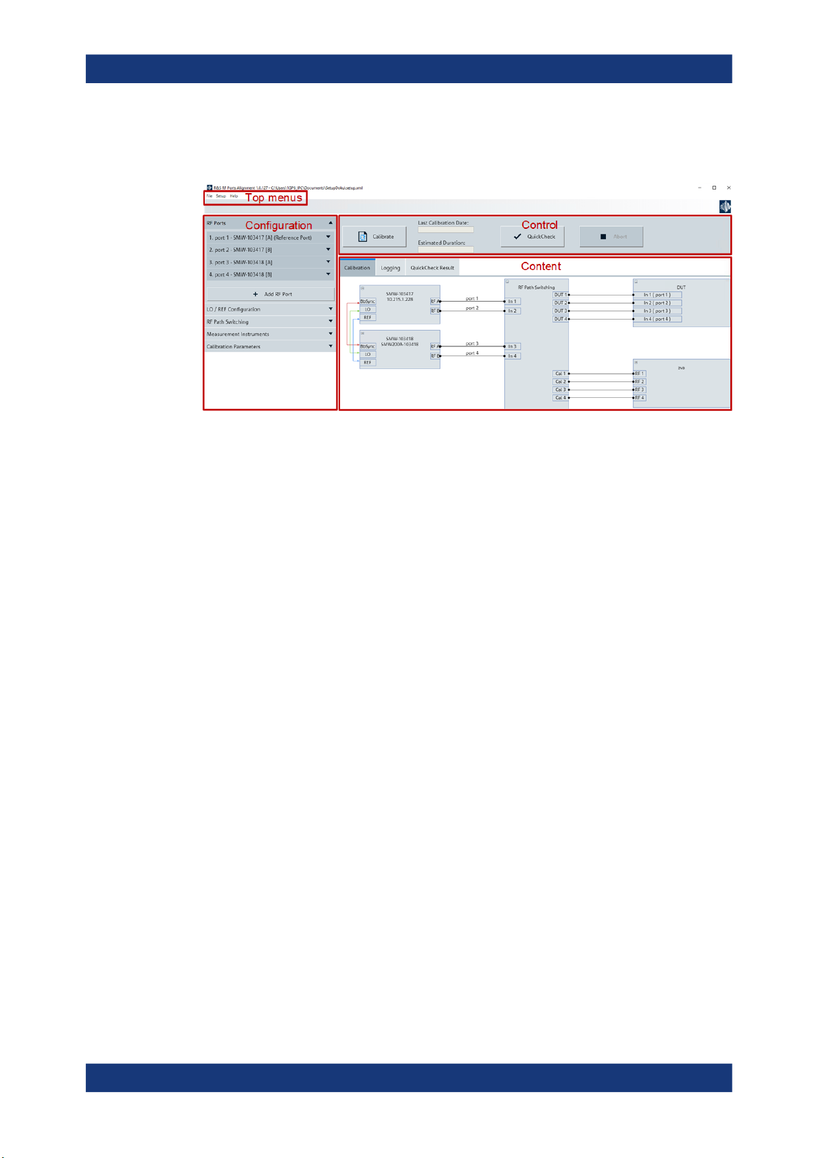
Figure 3-2: GUI overview
R&S RFPAL
GUI Overview
The graphical user interface is structured in three major areas:
●
Configuration
●
Control
●
Content
In the configuration area, you configure the setup for alignment measurements. The
settings can be saved via the top menu "File > Save Setup" or previous settings can be
loaded via "File > Load Setup".
You start and control the alignment measurements via "Calibrate" in the control area.
The information in the content area is distributed in several tabs:
●
The "Calibration" tab shows a graphical representation of the setup as configured
in the configuration area and used for the alignment measurements.
●
The "Logging" tab contains processing and status information and event reports.
You see what is going on. If errors occur, the information in this tab helps you to
understand the problem and how to solve it.
●
The "QuickCheck Result" displays charts for magnitude/phase/delay errors detected with a "QuickCheck" action. The "QuickCheck" runs the signal generators with
correction data applied and measures the remaining misalignments.
13User Manual 1179.1912.02 ─ 01
R&S®RFPAL, R&S®SMW-K545
3.3 Concepts
3.3.1 Test Setup for Alignment Measurements
R&S RFPAL
Concepts
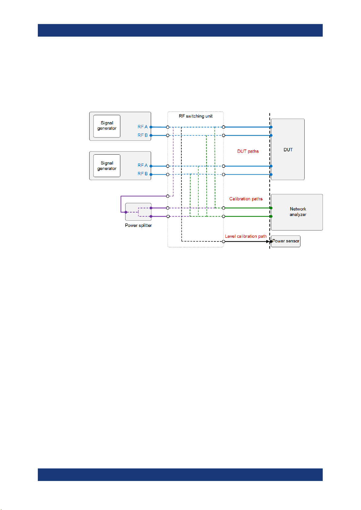
Figure 3-3: Test setup including an RF switching unit and relevant paths
The figure shows a useful instrument setup for RFPAL alignment measurements.
Characteristics:
●
The measurements instruments, a network analyzer and a power sensor, are
embedded in the test setup that is used for executing tests after alignment. No test
setup changes are required after alignment.
●
Optionally, an RF switching unit connects the RF signal path sections at the signal
generator side and the signal path sections at the DUT side. RFPAL controls the
switching unit. It can select the paths to be used for measurements, so the paths
are switched automatically during RFPAL operations. A configuration file is
required at the switching unit that defines the required paths.
If no switching unit is used, the required connections between RF ports and network analyzer have to be established manually (assisted by dialogs) during the
measurement procedures.
●
The components in the RF signal paths to the DUT can differ from the components
to the measurement instruments. So, DUT paths are distinguished from the corresponding calibration paths to the network analyzer and from the level calibration
path (corresponding paths: same signal generator's RF port). See in Integration of
S-Parameter Files how the different path types are used.
Tip: Use cables of the same length and type for corresponding paths and all RF
ports. Consequently, the relative signal deviations are minimized.
●
The power sensor is used for measuring the RF signal power at the reference port.
14User Manual 1179.1912.02 ─ 01

R&S®RFPAL, R&S®SMW-K545
●
For calibration of the network analyzer, a power splitter can be integrated in the
test setup. If an RF switching unit is used, the in port and the out ports of the power
splitter are connected to the switching unit, and the configuration file for the switching unit defines the RF paths through the power splitter. RFPAL commands the unit
to select the right RF paths to and from the power splitter for the calibration of the
network analyzer. So, no change of the test setup and no manual connection
establishment is required when proceeding from network analyzer calibration to
alignment measurements.
3.3.2 Integration of S-Parameter Files
The network analyzer carrying out the alignment measurements experiences the same
misalignments as the DUT if the DUT paths and the corresponding calibration paths
are equivalent. This is the case if the RF connections to both devices consist of the
same RF components (for example cables of the same type and lengths are used). So
the alignment measurements match the situation at the DUT, and applying RF port
alignment with the produced alignment data exactly aligns the RF signals at the DUT.
In other words, alignment is required at the DUT reference plane (see the figure), and
the measurement plane of the network analyzer matches the DUT reference plane.
R&S RFPAL
Concepts
Figure 3-4: Equivalent DUT and calibration paths
The DUT paths and calibration paths often contain different RF components, which
cause different signal deviations. These deviations have to be compensated for matching the situations at the measurement reference plane and the DUT reference plane.
See the figure for typical conditions.
15User Manual 1179.1912.02 ─ 01

R&S®RFPAL, R&S®SMW-K545
R&S RFPAL
Concepts
Figure 3-5: Different DUT paths and calibration paths that require S-parameter compensation
RFPAL integrates compensation of signal deviations from RF components in the RF
paths by S-parameter files (s<n>p files). The different RF path types are handled as
follows:
●
Calibration path: Gets the S-parameter files for the components in the RF signal
path between RF port and network analyzer, particularly for the switching unit.
RFPAL uses these S-parameter files for compensating deviations in these paths
during the alignment measurements. So alignment data is produced as if the measurements were carried out in the RF ports reference plane. Applying the S-parameter files shifts the measurement reference plane to the RF ports reference plane.
●
DUT path: Gets the S-parameter files for cables, splitters and other components in
that path. RFPAL forwards these calibration files to the primary signal generator
after the alignment measurements. They are applied by the signal generators to
compensate the signal deviations in the DUT paths. In combination with alignment
data related to the RF ports reference plane, the DUT gets aligned RF signals.
Applying the S-parameter files can be seen as deembedding of the DUT: By
removing the signal deviations between the RF ports of the signal generators and
the DUT, the reference plane where the RF signals are aligned is shifted from the
RF ports reference plane to the DUT reference plane.
●
Level calibration path: Gets the S-parameter files for the components in the RF signal path between reference port and power sensor. RFPAL uses these S-parameter files in the same way as those for the calibration paths.
Measuring the frequency responses of the RF components in the different RF paths is
not part of RFPAL. Usually, the frequency responses of the RF components are known
and s<n>p calibration files for them are already available.
16User Manual 1179.1912.02 ─ 01

R&S®RFPAL, R&S®SMW-K545
3.3.3 Alignment Measurements
The figure shows schematically how misalignments between two RF ports of one or
two signal generators are measured with a network analyzer.
R&S RFPAL
Concepts
Figure 3-6: Alignment measurement for RF A and RF B
With connections between the reference port and a second RF port to the network
analyzer established, RFPAL commands the signal generators to generate appropriate
RF signals. Instead of continuous-wave signals to be swept over the signal bandwidth,
multi-carrier continuous wave (MCCW) signals are used. The network analyzer measures the differences between the RF signals over the frequencies and over signal
power levels as configured in RFPAL.
Afterwards, if more than two RF ports have to be aligned, the second RF port is
changed and the same alignment measurement is carried out for the new pair of reference port and second RF port, and so on for all RF ports to be aligned. So, the reference port is always connected to the same input port of the network analyzer and the
second port changes for each measurement. The connection to the next RF port is
changed either automatically via RF switching box under control of RFPAL or manually.
Power measurement with the power sensor is performed only for the reference port
(relative power differences between the reference port and the other RF ports are
already covered by the network analyzer measurements).
3.3.4 Calibration of the Network Analyzer
RFPAL supports calibration of the network analyzer. Two ports of the network analyzer
are used to measure the signal differences of two RF ports of the signal generators.
Calibration of the network analyzer makes sure that any differences in the frequency
responses of the receivers behind the ports are compensated and do not influence the
alignment measurements. For determining the differences of frequency responses in
17User Manual 1179.1912.02 ─ 01

R&S®RFPAL, R&S®SMW-K545
the network analyzer, the same RF signal is fed to the two ports. The network analyzer
measures and evaluates the differences between the responses.
If direct receiver access is enabled for the network analyzer, its "Ref" and "Meas" connectors can alternatively be used (there is a receiver behind "Ref" and one behind
"Meas"). Notice that when using direct receiver access, the standard calibration of the
network analyzer is no more valid.
Two methods for calibration of the network analyzer are supported:
●
Power splitter method: The primary signal generator generates appropriate RF signals and transmits them to a power splitter where they are split. The resulting two
identical RF signals are fed to the two network analyzer receivers to be calibrated.
RFPAL controls both the primary signal generator and the network analyzer and
applies the s<n>p calibration file of the power splitter. This method fits to the test
setup that is later used for testing. Only the power splitter is added to the test setup
and its connections have to be established.
R&S RFPAL
Concepts
Figure 3-7: Calibration of network analyzer with power splitter and signal generator
Use the power splitter method for the R&S ZVA. The following method is not valid
for this instrument.
●
TOSM method: This calibration type yields the most accurate calibration results
(reflection and transmission measurements; 12-term error correction model). It
relies on automatic calibration procedures of the network analyzer. Equivalent VNA
standard calibration is also possible.
TOSM (Through – Open – Short – Match) calibration can be done in two ways. For
both, the network analyzer generates RF signals, transmits them to and through
standard units, measures the responses and evaluates the differences between
generated RF signals and responses:
– Using a calibration kit for the network analyzer: The Short, Open and Match
standard from the kit are connected to one port, the Through standard is put
between this port and the second one. See the network analyzer's documentation. RFPAL is not involved. This calibration must be done at the network analyzer before RFPAL is used. RFPAL just gets the name of the resulting calibration file.
– Using a calibration unit: It replaces the standards from a calibration kit, and full
automation is possible. See again the network analyzer's documentation.
Though the calibration procedures are carried out completely at the network
analyzer, RFPAL assists for this type of calibration: If the calibration unit is inte-
18User Manual 1179.1912.02 ─ 01

R&S®RFPAL, R&S®SMW-K545
grated in the test setup at RFPAL, RFPAL can control not only the network analyzer but also the calibration unit and the calibration. The results of the calibration are stored in a calibration file which the user has to specify in RFPAL. Later
on, RFPAL loads this file onto the network analyzer.
3.3.5 Delivery of Correction Data
Having completed the alignment measurements, RFPAL delivers the alignment data
and s<n>p files for the DUT paths for all RF ports to the primary signal generator (via
*.rfsa archive file). The combination of alignment and s<n>p data is called correction
data. Further distribution of the correction data and application of the correction data,
which aligns the RF signals, is done at the signal generators without participation of
RFPAL.
3.3.6 QuickStep Behind the Scene
R&S QuickStep is an application that configures test procedures, runs test plans –
sequences of individual tests together with scheduling and execution information – and
evaluates the results. During test execution, R&S QuickStep controls the test equipment via SCPI commands. R&S QuickStep also provides the calibration and alignment
procedures.
R&S RFPAL
Preparing for Use
The alignment procedures cover the typical use cases. To adapt the alignment procedures for special test scenarios, it is possible to modify the alignment procedures.
Therefore, the R&S QuickStep development option is required.
3.4 Preparing for Use
3.4.1 Preliminaries
3.4.1.1 Required Hardware
RFPAL is intended to be used on a PC. No special hardware and other software is
required. The tool runs on Windows 7 or 10.
3.4.1.2 Required Options
R&S RFPAL is not related to a software option. Instead, options are required for the
R&S SMWs to interplay with RFPAL and to use the alignment data, particularly R&S
SMW-K545 RF ports alignment.
Note that R&S RFPAL includes a QuickStep standard option to perform the alignment
procedures. For modifying the alignment procedures (only for special use cases,
19User Manual 1179.1912.02 ─ 01

R&S®RFPAL, R&S®SMW-K545
expert knowledge required), the QuickStep development option (R&S QS-DEV) is
required.
3.4.2 Installing and Starting RFPAL
Installing RFPAL
The tool is provided as .exe installation file. You install the tool on the PC that controls
the alignment procedures.
1. Download the installation file from the following destination.
https://www.rohde-schwarz.com/software/rfpal
2. Double-click the file.
An installation dialog guides you through the installation process.
3. Accept the license conditions and click "Next".
RFPAL is installed on your PC. An "R&S RFPAL" icon is added on the desktop for
starting the tool.
R&S RFPAL
Operation
Starting the tool
► Double-click the "R&S RFPAL" icon on the desktop.
The application starts and its graphical user interface opens with a start page.
Either click "New setup" to create a setup file that has only some default settings
and that you fill with configuration data. Or click "Load setup" to load a setup file
from an earlier RFPAL session. Then, the actual RFPAL GUI is opened representing the settings stored in the setup file.
3.5 Operation
RFPAL is operated by a sequence of steps.
●
Configure the Setup
●
Configure RF Path Switching and the Measurement Instruments
●
Configure the Alignment Measurements
●
Execute the Measurements and Transfer Correction Data
Prerequisites
Before applying the following procedures:
●
Make sure that the cabling connections have been established. Particularly, RFPAL
needs LAN connections to the instruments to be controlled.
●
Switch on the instruments.
20User Manual 1179.1912.02 ─ 01

R&S®RFPAL, R&S®SMW-K545
Set up all instruments at once in the connection configuration dialog when opening it
the first time during the RFPAL configuration (see Connection configuration dialog).
Then, you only have to select the right instruments in the later RFPAL configuration
steps.
3.5.1 Configure the Setup
The setup of the signal generators and the connections is configured by parameters in
the "RF Ports" and "LO/REF Configuration" sections of the configuration area on the
left side. After saving the configuration, the "Calibration" tab displays a schematic diagram of the instruments and paths as configured.
Use case
No setup is loaded. Instead, a new setup is built by configurations in the "Calibration"
area.
Prerequisites
R&S RFPAL
Operation
●
S-parameter files for the components in the RF paths (between RF ports and the
DUT and the measurement instruments) are available if needed (see Integration of
S-Parameter Files).
To configure the RF ports (including signal generators and RF paths)
1. Select "File > New Setup" from the top menu, enter a filename for the .xml file that
describes the setup and store the file.
2. Select "RF Ports" in the configuration area on the left.
3. For each RF port in your physical test setup, add an RF port section by clicking the
"+ Add RF Port" field, and configure each section as described in the following
steps.
4. Enter an RF port name from the loaded test setup for "RF Port Name".
Note: The first RF port is always the reference port. The signal generator with that
port is the primary instrument.
5. Open the "Config" dialog, add the signal generator for the RF port (for example
with "Search Instrument" if the instrument is already connected and running in the
LAN).
6. Click "Save & Select" while the row for the signal generator is highlighted. The dia-
log is closed and the device name of the signal generator from the "Config" dialog
is displayed in the "Device Name" field.
7. Select the used "RF Port".
8. For the components in the signal path from the signal generator's RF port to the
DUT, add the related S-parameter files in the "DUT Path" section. Therefore, start
with "Add Row".
21User Manual 1179.1912.02 ─ 01

R&S®RFPAL, R&S®SMW-K545
9. For the components in the signal path from the signal generator's RF port to the
calibration instrument (for example a network analyzer), add the related S-parameter files in the "Calibration Path" section. Therefore, start with "Add Row".
10. For the reference port of the primary instrument, the "Level Calibration Path" sec-
tion is available. For the components in the signal path from the reference port to
the level calibration instrument (power sensor), add the related S-parameter files in
the "Calibration Path" section. Therefore, start with "Add Row".
To configure the local oscillator and the reference signal
In this example procedure, it is assumed that the primary signal generator provides the
local oscillator and the REF signal, all secondary signal generators get the LO and
REF signals from the primary instrument.
Default settings are provided for this use case. So, if you decide to operate with this
use case, you can omit the following procedure. Nevertheless, the procedure illustrates
exemplarily how to configure in this section.
1. Select "LO / REF Configuration" in the configuration area on the left.
R&S RFPAL
Operation
2. Configure the parameters according to your physical test setup.
● Enable "LO Coupling".
● Select "Star" for the "LO Configuration".
● Select "Intern" for the "LO Source".
● Select "Intern" for the "REF Source".
To save the configuration
► Select "File > Save Setup" from the top menu.
Vice versa, you get the saved configuration via "File > Load Setup".
3.5.2 Configure RF Path Switching and the Measurement Instruments
RF path switching means changing one connection between an RF port of a signal
generator and the network analyzer (the other connection to the reference RF port is
kept).
Measurement instruments are the network analyzer and the power sensor.
To configure the RF path switching
If an RF switching unit is integrated in the test setup, you can use automatic switching:
RFPAL commands the switching unit to establish the required connections.
Else, manual switching is required where you reconnect manually.
1. Select "RF Path Switching" in the configuration area on the left.
2. Select the "Switching Mode" according to your needs.
3. In case of "Automatic" "Switching Mode":
22User Manual 1179.1912.02 ─ 01

R&S®RFPAL, R&S®SMW-K545
● Configure and select the RF switching unit via the "Config" dialog.
● Enter the name of the configuration file that defines the mapping between the
ports of the RF switching unit and the RF path sections (this file must be available on the RF switching unit).
To configure the network analyzer
Calibration of the network via power splitter is included. See Calibration of the Network
Analyzer for details.
1. Expand "Measurement Instruments" in the configuration area on the left. Make
sure that the checkbox at the "Vector Network Analyzer" field is ticked and expand
the field.
2. Get the "Device Name" of the network analyzer via the Config dialog and "Save &
Select".
If the network analyzer is not yet available in the "Config" dialog, add the instrument in the dialog and select it.
3. "Number of Ports" shows how many ports of the network analyzer are used for the
alignment measurements. This parameter is read-only.
R&S RFPAL
Operation
4. Keep "Direct Receiver Access" disabled.
5. Select "Power Splitter" for the "Calibration Mode".
A table for S-parameter files is displayed.
6. Select the S-parameter file for compensating signal deviations by the power splitter
(only for calibration).
To configure the power meter
1. Still in the "Measurement Instruments" area, make sure that the checkbox at the
"Power Meter" field is ticked and expand the field.
2. Get the "Device Name" of the power meter via the "Config" dialog and "Save &
Select".
To save the configuration
► Select "File > Save Setup" from the top menu.
3.5.3 Configure the Alignment Measurements
The configurations for the alignment measurements are done in the "Calibration
Parameters" section in the configuration area on the left.
To configure the RF signals for alignment measurements
1. Select "Calibration Parameters" in the configuration area on the left.
2. Specify the carrier frequencies used for the calibration measurements.
23User Manual 1179.1912.02 ─ 01

R&S®RFPAL, R&S®SMW-K545
3. Specify the power levels (peak envelope power, PEP) used for the calibration measurements.
4. Specify the modulation bandwidth of the signal.
Alignment measurements are carried out with two independent loops for frequency
and power level as specified above.
3.5.4 Execute the Measurements and Transfer Correction Data
Use case: Calibration of the network analyzer is included as well as power measurements with a power sensor. The RF paths are switched manually (no RF switching unit
used).
1. In the control area above the main display area, click "Calibrate" to launch the
measurements.
The estimated duration of the measurement procedures is shown. Click "Ok" to
continue.
R&S RFPAL
Operation
2. A calibration dialog for the network analyzer opens. Follow the instructions.
The two ports of the network analyzer used for the alignment measurements are
calibrated.
3. A dialog opens requesting to connect the power sensor to RF port 1. Follow the
instructions.
The power meter measures the output power of the reference port over the configured signals.
4. Make sure that the reference port and the second RF port are connected with the
network analyzer. If a low signal level is detected, the user is requested to verify or
establish the connections.
The network analyzer measures the differences of the frequency responses at the
two ports.
5. A calibration dialog opens that requests you to establish the next required RF connection.
Establish the RF path connections as requested and click "Ok".
The network analyzer performs the alignment measurements for the two ports.
6. For all remaining RF ports configured beforehand: The calibration dialog opens
again. The first RF port is the same as before, the second RF port is the next one
not measured yet.
Connect the RF paths as requested and click "Ok".
Again, the network analyzer performs the alignment measurements.
7. When measurements are complete for all RF ports, a distribute corrections dialog
opens.
Click "Ok" to have the calibration and correction data delivered to the primary
instrument.
24User Manual 1179.1912.02 ─ 01

R&S®RFPAL, R&S®SMW-K545
An *.rfsa archive file is transferred to the /var/user/ directory on the primary signal generator. It includes the alignment data derived from the alignment measurements, the *.s<n>p files for the DUT paths and the setup configuration.
3.6 GUI Description
The graphical user interface (GUI) is structured by the following areas:
●
Top Menus on top of the GUI
●
Control Area above the main content area
●
Configuration Area on the left
●
Content Area structured with tabs
3.6.1 Top Menus
R&S RFPAL
GUI Description
3.6.1.1 File
New Setup [Ctrl + n]
Opens a file explorer for creating and saving a new setup.xml setup file. A folder is
created which has the name you specify and which contains setup.xml where the
configurations are saved.
Load Setup [Ctrl + l]
Opens a file explorer for navigating to an .xml setup file. Select the file of interest and
click "OK" to have it loaded. The settings of the setup file are loaded in the configuration area, a graphical representation is displayed in the "Calibration" area.
Default directory for setup files:
C:\Users\Public\Documents\Rohde-Schwarz\QuickStep\Projects\
RfPortsAlignment\Setups
Save Setup [Ctrl + s]
Saves the current configuration in the new or loaded setup file.
Save Setup As [Ctrl + Shift + s]
Opens a file explorer and lets you save the current configuration under the path you
select and with the filename you enter.
Import Corrections
Loads correction data from a file explorer into RFPAL. The correction data is contained
in an *.rfsa file. If the current setup fits to the correction data, you can do a "QuickCheck" to control the quality of the corrections.
25User Manual 1179.1912.02 ─ 01

R&S®RFPAL, R&S®SMW-K545
Export Corrections
Saves the current corrections in an *.rfsa file under a selectable path. Afterwards,
you can import them on an R&S SMW.
Default directory for correction files:
C:\Users\Public\Documents\Rohde-Schwarz\QuickStep\Projects\
RfPortsAlignment\Results
Exit [Ctrl + q]
Closes the application.
3.6.1.2 Help
Provides version information about the tool and the operating help.
3.6.2 Control Area
Controls the execution of alignment measurements.
R&S RFPAL
GUI Description
Figure 3-8: Control area
Calibrate
Starts the alignment measurements. The procedure can include the calibration of the
network analyzer.
Last Calibration Date
Provides the date and time when the last "Calibrate" procedure has been executed for
the loaded (current) setup.
Estimated Duration
The expected duration of the "Calibrate" procedure for the loaded (current) setup.
QuickCheck
Makes the signal generators generate RF signals with alignment applied using the current RFPAL correction data and measures the remaining misalignments. The results of
the QuickCheck are shown in the "QuickCheck Result" tab. The QuickCheck measures
the quality of alignment with the current correction data. The measurements are carried
out for the carrier frequencies and power values (the calibration points) configured in
the "Calibration Parameters" section.
The QuickCheck is useful, for example, for checking if earlier correction data still lead
to sufficiently aligned signals.
Abort
Stops the currently running alignment measurement without saving the results.
26User Manual 1179.1912.02 ─ 01
R&S®RFPAL, R&S®SMW-K545
3.6.3 Configuration Area
This area contains configuration menus. The settings are applied on the loaded setup.
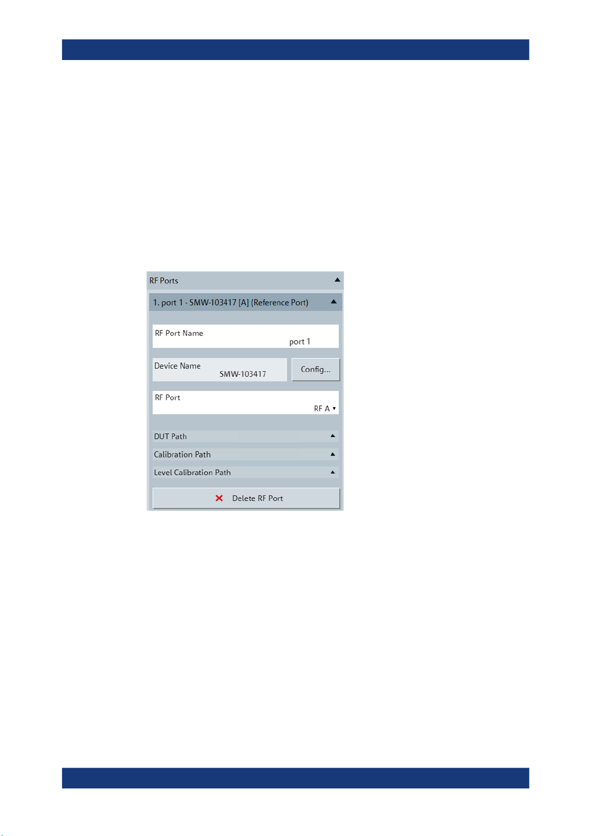
3.6.3.1 RF Ports
Specifies the sources for the RF signals at the RF ports and the calibration files for the
RF paths. Each RF path gets an own, numbered section denoted by an RF port name
and is defined by an RF signal generator and an RF port of that generator. DUT paths
are distinguished from calibration paths due to different path components and related
s<n>p calibration files.
The first port in the configuration area is always the reference port.
R&S RFPAL
GUI Description
Figure 3-9: RF Ports
RF Port Name
A descriptive name for the RF port and the related RF paths. It appears in the headline
of the section for the RF port and path.
Device Name
The name of the instrument as displayed in the connection configuration dialog and in
the setup figure. Select the device name via the connection configuration dialog.
Config
Opens the connection configuration dialog where you specify the RF signal generator
for remote control by RFPAL. See Common Configurations.
27User Manual 1179.1912.02 ─ 01

R&S®RFPAL, R&S®SMW-K545
RF Port
Selects an RF port of the signal generator, for example, "RF A" or "RF B" for an R&S
Signal Generator.
DUT Path
A table imports the S-parameter files for compensating signal deviations by RF components in the signal path between RF port and DUT. Each table row displays one Sparameter file.
●
Add or delete a row with the "Add Row" and "Delete Row" buttons.
A default file name and a file explorer icon are shown in the new row.
●
The "S-Parameter File" column displays the filename of an imported S-parameter
file. This S-parameter file will be transmitted to the primary signal generator at the
end of the alignment procedure.
●
Click the file icon in the "File Manager" column to open a file explorer. Then select
the S-parameter file and click the "Import ..." button to import the file.
●
In the "Ports to" and "Ports from" columns, describe the start and end point of the
DUT path section that is covered with the imported S-parameter file (information
only).
R&S RFPAL
GUI Description
Calibration Path
A table imports the S-parameter files for compensating signal deviations by RF components in the signal path between RF port and network analyzer. Each table row displays one S-parameter file. S-parameter handling is the same as for the "DUT Path".
Level Calibration Path
Only available for the first RF port, that is the reference port. A table imports the Sparameter files for compensating signal deviations by RF components in the signal
path between reference port and power measurement instrument. Each table row displays one S-parameter file. Handling in the table is the same as for the "DUT Path".
Delete RF Port
Removes the complete RF port section (beginning with the number and RF port
name).
3.6.3.2 LO / REF Configuration
Configures the source of the LO local oscillator and the REF reference signal and how
these signals are utilized. The configured connections from the local oscillator to the
signal generators and the REF connections are displayed in the "Calibration" tab of the
content area.
28User Manual 1179.1912.02 ─ 01

R&S®RFPAL, R&S®SMW-K545
Figure 3-10: LO / REF configuration and its graphical representation
R&S RFPAL
GUI Description
LO Coupling
LO coupling enabled (ticked checkbox) makes sure that the signal generators get the
local oscillator signals from the same source. Disabling is not possible to avoid phase
differences of the local oscillators which cause RF signal misalignments.
LO Configuration
●
Select "Star" if the signal generators get the local oscillator signals directly (with a
direct connection) from the same source.
●
Select "Daisy Chain" if the local oscillator signal is forwarded from one signal generator to the next one.
LO Source
●
"Internal": The local oscillator from one of the signal generators is used.
●
"External": The local oscillator from an additional instrument is used.
LO Source Device
Available for "External" "LO Source". Specifies the device name of the instrument in
the setup that provides the local oscillator signals. Select this device name via the
"Config" dialog.
Config
Available for "External" "LO Source". Opens the connection configuration dialog where
you specify the local oscillator instrument for remote control by RFPAL. See Common
Configurations.
LO / REF Filename
Available for "External" "LO Source". Specifies the filename of the correction file which
compensates the pathloss between LO source instrument and signal generators.
29User Manual 1179.1912.02 ─ 01

R&S®RFPAL, R&S®SMW-K545
REF Source (Reference Port)
Specifies the source instrument for the REF reference signal.
●
"Internal": REF originates at the primary signal generator.
●
"External": REF originates at an additional instrument.
3.6.3.3 RF Path Switching
Specifies how the signal paths are switched during the alignment measurements.
R&S RFPAL
GUI Description
Figure 3-11: RF path switching
Switching Mode
Specifies how the second RF port is changed for the next alignment measurement (the
first port is the reference port which is kept for all measurements).
●
"Manual": After one alignment measurement, a dialog requests two RF ports to be
connected to the network analyzer. Establish the connections manually. This mode
is required if the test setup does not contain a switching unit.
●
"Automatic": Requires that an RF switching unit is contained in the test setup that
can control the RF paths used for the measurements. RFPAL controls the switching unit. For example, when proceeding from one to the next alignment measurement, RFPAL automatically commands the switching unit to establish the required
connections.
Device Name
Available for "Automatic" RF switching. Specifies the name of the switching unit as displayed in the connection configuration dialog. Select this device name via the "Config"
dialog.
Config
Available for "Automatic" RF switching. Clicking the button opens the "Config" dialog
where you configure the switching unit (required in this case) for remote control by
RFPAL. See Common Configurations.
Config File Name
Available for "Automatic" RF switching. Specifies the filename of the configuration file
to be used by the RF switching unit. The file defines the paths used within the RF
switching unit. RFPAL expects the configuration file to be available at the switching
unit.
30User Manual 1179.1912.02 ─ 01

R&S®RFPAL, R&S®SMW-K545
The figure shows an example for a configuration file. In1, In2, In3, In4 refer to the In
ports of the RF switching unit; In1 is related to the reference port of the primary signal
generator. Cal1, Cal2, Cal3, Cal4 refer to the Out ports of the RF switching unit connecting to the network analyzer, Cal0 to the Out port to the power meter. These port
names are also displayed in the test setup figure in the "Calibration" tab of the content
area.
R&S RFPAL
GUI Description
Figure 3-12: Content of RF switching configuration file (example)
The first line in the configuration file denotes the signal routing from the In1 port to the
Out ports Cal1, Cal2, Cal3, Cal4. Hence the signal from In1 is split and distributed to all
these Out ports; this routing is related to the calibration of the network analyzer using
RF signals from the reference port. The second line defines the internal connections
for that signal routing. These connections have to be configured by the user. See the
"R&S OSP Open Switch and Control Unit" user manual for details. The following pairs
of lines define individual paths. For example, In1_Cal0 connects the reference port with
the power meter, the path is realized within the switching unit by the internal connection configuration 1100011,1100116,1200014,1300013,1300012.
3.6.3.4 Measurement Instruments
This area configures the instruments which carry out the alignment measurements.
31User Manual 1179.1912.02 ─ 01

R&S®RFPAL, R&S®SMW-K545
R&S RFPAL
GUI Description
Figure 3-13: Measurement instruments
Vector Network Analyzer
The network analyzer measures the differences between the signals from the reference port and from other signal generator RF ports.
Vector Network Analyzer checkbox
Enables or disables the network analyzer for alignment measurements.
Device Name
The name of the measurement instrument as displayed in the "Config" dialog and in
the setup figure. Select the device name via the "Config" dialog.
Config
Opens the connection configuration dialog where you specify the calibration instrument
for remote control by RFPAL. See Common Configurations.
Number of ports
Number of ports of the measurement instrument that are used for alignment measurements. For example, two ports of a network analyzer are used: "Port 1" connected to
RF port A of the primary instrument, "Port 2" connected to RF port B of the primary
instrument.
32User Manual 1179.1912.02 ─ 01

R&S®RFPAL, R&S®SMW-K545
Direct receiver access
Direct receiver access is only possible if the network analyzer is equipped with "Ref",
"Source" and "Meas" pairs of SMA connectors for each port according to hardware
option R&S ZNA...-B16. If enabled, "Ref" and "Meas" of one port of the network analyzer is used for alignment measurements ("Number of ports" = 1 in this case). "Ref" is
connected to the RF path of the reference RF port (of the primary instrument) "Meas"
to the second RF port.
The SMA connectors give direct access to the RF input and output signal paths, here
to the "Ref" and "Meas" receivers.
Calibration mode
Defines the calibration method of the network analyzer.
TOSM ← Calibration mode
Select this option if calibration of the network analyzer is done with Through – Open –
Short – Match standards connected to the network analyzer or with a calibration unit
that integrates all standards.
Use calibration unit ← TOSM ← Calibration mode
Tick the checkbox if you use a calibration unit for calibration of the network analyzer.
The calibration unit is directly connected with the network analyzer's ports to be used
for the later alignment measurements. At least two network analyzer ports are
required.
R&S RFPAL
GUI Description
Calibration filename ← TOSM ← Calibration mode
Specifies the filename of the .cal calibration file for the measurement instrument. If
calibration is carried out under control of RFPAL, RFPAL generates the calibration file
and forwards it to the network analyzer. If calibration was carried out beforehand without RFPAL, the calibration file is expected to be available at the network analyzer.
Power splitter ← Calibration mode
Select this option if a power splitter is used to get the same RF signal from a signal
generator twice for the two ports of the network analyzer. See Calibration of the Net-
work Analyzer for details.
The power splitter is an additional (passive) device in the test setup, so specify the Sparameter file to compensate errors from this device. See DUT Path for a description
of the S-parameter table.
If direct receiver access is enabled, two S-parameter files can be specified per network
analyzer port since each port offers two separate RF paths ("Ref" and "Meas") that can
include error-causing components to be compensated.
Power Meter
A power meter, for example an R&S NRP, is used for measuring the output power levels for the reference port of the primary signal generator.
Power Meter checkbox
Enables or disables the power meter for alignment measurements.
33User Manual 1179.1912.02 ─ 01

R&S®RFPAL, R&S®SMW-K545
Connected to Master
Tick the checkbox if the power meter is directly connected to the primary signal generator. RFPAL controls the power meter via the primary instrument.
Keep the checkbox unticked if the power meter is connected to the primary signal generator via RF cables (and RF switching box if used). In this case, *.s<n>p files have
to be provided at the "Level Calibration Path" for the reference port configuration to
compensate the signal errors caused by the RF connection.
Device Name
The name of the measurement instrument as displayed in the "Config" dialog and in
the setup figure. Select the device name via the "Config" dialog.
Config
Opens the connection configuration dialog where you specify the instrument for remote
control by RFPAL. See Common Configurations.
3.6.3.5 Calibration Parameters
R&S RFPAL
GUI Description
Frequency Control
Alignment measurements are performed over a set of RF signals characterized by their
carrier frequencies and the modulation bandwidth of a signal. This section specifies the
carrier frequencies as set of RF frequencies.
Note that a second independent loop of measurements over power level is performed
(one power level loop for each RF frequency).
Mode
Specifies how the RF frequencies are provided for the alignment measurements.
Range ← Mode
Define the RF frequencies by the "Start", "Stop " and "Step" parameters.
Start ← Range ← Mode
The first RF frequency used in the loop of alignment measurements with varied RF frequency.
Stop ← Range ← Mode
The last RF frequency used in the loop of alignment measurements with varied RF frequency.
Step ← Range ← Mode
The frequency increment to get the next RF frequency.
List ← Mode
Define the RF frequencies via a file that contains a list of frequencies.
Values ← List ← Mode
Displays the frequencies contained in the imported list of frequencies.
34User Manual 1179.1912.02 ─ 01

R&S®RFPAL, R&S®SMW-K545
Import Values ← List ← Mode
Opens a file explorer to select a .csv file that contains the comma-separated list of
frequencies (in GHz, units not included in the file) for which alignment measurements
are executed.
Modulation Bandwidth
Specifies the frequency range of the RF signal around the carrier frequency. For each
carrier frequency specified in the "Frequency Control" section, the alignment measurements cover the modulation bandwidth around the carrier frequency.
You get a higher resolution for the frequency response measurements if you reduce
the modulation bandwidth.
Level Control
Alignment measurements are performed over a range of power levels, one loop over
power levels for each RF frequency defined in the "Frequency Control " section. Here,
the power levels refer to the peak envelope power (PEP) of the RF signal received at
the DUT.
R&S RFPAL
GUI Description
Mode
Specifies how the power levels are provided for the alignment measurements.
●
Value "Range" displays the "Start", "Stop "and "Step" parameters to define the
power range.
●
Value "List" displays the "Value" parameter and the "Import Values" field to define
the power values via a file.
Range ← Mode
Define the power levels by the "Start", "Stop " and "Step" parameters.
Start ← Range ← Mode
The first power level used in the loop of alignment measurements with varied RF
power.
Stop ← Range ← Mode
The last power level used in the loop of alignment measurements with varied RF
power.
Step ← Range ← Mode
The increment to get the next power level.
List ← Mode
Define the power levels via a file that contains a list of power values.
Values ← List ← Mode
Displays the power levels contained in the imported list of power values.
Import Values ← List ← Mode
Opens a file explorer to select a .csv file that contains the list of power values (in
dBm; units not included in the file) for which alignment measurements are executed.
35User Manual 1179.1912.02 ─ 01

R&S®RFPAL, R&S®SMW-K545
3.6.3.6 Common Configurations
Figure 3-14: Connection configuration dialog
R&S RFPAL
GUI Description
Connection Configuration Table
The table contains the following columns:
●
"Device Name": A descriptive name for the instrument. That name appears in the
setup figure.
●
"VISA Resource": The VISA resource string used to connect to the instrument.
●
"Timeout [ms]": The maximum waiting time for the instrument to respond to a connection attempt.
●
"Hostname/IP": The hostname or IP address of the signal generator to be
accessed via VISA.
●
"Check Connection": Click the "Check" button to attempt to establish the connection to the target instrument using the string in the "VISA Resource" column. An
*IDN? request is sent to the instrument and the result of the attempt is reported.
●
"Status": The connection status to the instrument.
Buttons
The buttons above the table on the left side filter for device types. The buttons below
the table provide VISA utilities.
SMW
Filters the table for instruments of type SMW (signal generators).
ZNA/ZVA
Filters the table for instruments of type ZNA and ZVA (vector signal analyzers).
All Devices
Removes previous filtering of the table. All table rows are displayed.
36User Manual 1179.1912.02 ─ 01

R&S®RFPAL, R&S®SMW-K545
Clear List
Removes all entries in the table.
Search Instrument
Searches for connected VISA instruments in the LAN and displays them in a dialog.
Select a detected instrument and click the "Add" button to add it to the table.
Add Instrument
Appends a new row in the table with default settings.
Remove Instrument
Removes the currently selected row in the table.
Save & Select
Saves the changes in the table and copies the device name of the currently selected
row into the "Device Name" in the current section of the RFPAL configuration area.
3.6.4 Content Area
R&S RFPAL
GUI Description
This area contains a graphical representation of the setup, logging data from calibration and alignment measurements and results.
3.6.4.1 Calibration
This area shows a schematic test setup which is a graphical representation of the configuration in the configuration area. If the configuration is changed, the graphical representation is adapted accordingly.
Figure 3-15: Calibration tab
37User Manual 1179.1912.02 ─ 01

R&S®RFPAL, R&S®SMW-K545
The "RF Path Switching" field between signal generators on the left and DUT and measurement instruments on the right can be seen as representation of an RF switching
unit if this device is contained in the physical test setup. Else, the crossbar has no
physical counterpart but structures the different paths.
3.6.4.2 Logging
This area lists processing and status information, error and event reports.
R&S RFPAL
GUI Description
Figure 3-16: Logging tab
The "Source" column indicates the component where the reported information has its
origin. "QS Engine" is the QuickStep software that executes the procedures.
Click the "Clear" button to remove all displayed log information.
3.6.4.3 QuickCheck Result
This area displays charts for magnitude/phase/delay errors vs. power resulting from a
"QuickCheck". This action runs the signal generators with alignment applied and measures the remaining signal errors. Each chart shows errors versus the power values
configured in the "Calibration Parameters" section, and error curves are provided for
each carrier frequency configured in "Calibration Parameters" section. So, you can see
magnitude/phase/delay errors for all configured carrier frequencies and power values.
The error curves for the different carrier frequencies are color-coded. See the "Filter"
section to relate the color to the frequency.
38User Manual 1179.1912.02 ─ 01
R&S®RFPAL, R&S®SMW-K545
R&S RFPAL
GUI Description
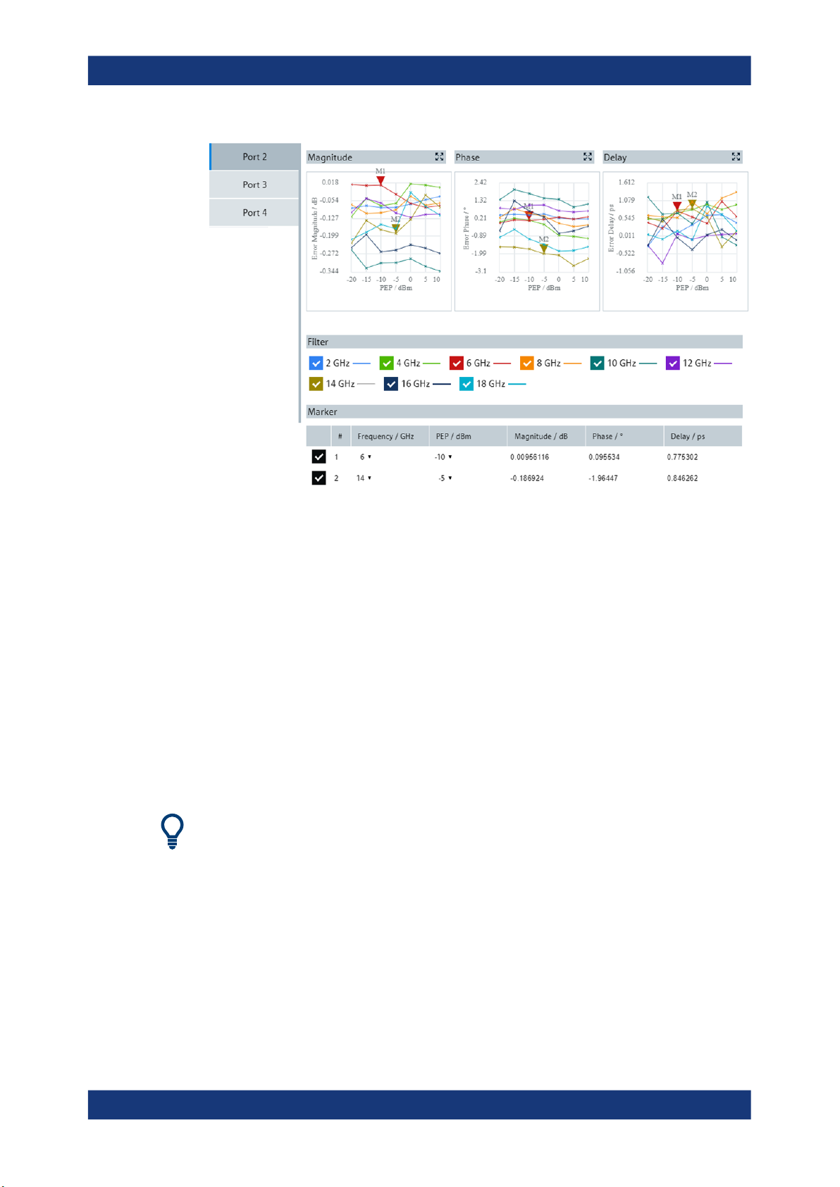
Figure 3-17: QuickCheck Result tab
Filter
In the "Filter" section, you select the carrier frequencies for which error curves are displayed in the charts.
Marker
You tick a checkbox in the left column of the displayed table to activate a marker. And
you select the carrier frequency and power for the marker in the "Frequency" and
"PEP" columns. Consequently, in each chart, a marker is displayed at the measurement value for the selected PEP power and at the curve related to the selected frequency. In the columns to the right side, the table rows show the values for the magnitude, phase and delay errors at the marker position.
Up to two markers can be activated corresponding with the two rows of the table.
You can change the horizontal position of a marker in the charts by dragging it to the
left or right via the mouse cursor.
39User Manual 1179.1912.02 ─ 01

R&S®RFPAL, R&S®SMW-K545
4 RF Ports Alignment at the SMWs
For aligning the signals at the RF ports of the signal generators in the test setup, the
signal generators apply the correction data from RFPAL. RFPAL delivers the correction
data as *.rfsa archive file to the primary signal generator. The correction data
include alignment and s<n>p data. The primary instrument takes over control of the
own RF ports alignment and that of the secondary instruments. It distributes the correction data to the secondary instruments, and the secondary instruments are configured accordingly. At start of operation (test execution), the primary instrument checks
the status of all secondary devices to check for errors and retrigger the instruments for
synchronous update of the correction data.
No configurations are needed at the secondary instruments. The following descriptions
refer to the primary signal generator only.
4.1 How to Use RF Ports Alignment at the primary Signal
RF Ports Alignment at the SMWs
How to Use RF Ports Alignment at the primary Signal Generator
Generator
When the *.rfsa file arrives at the primary instrument and it is valid, multi-instrument
usage and RF ports alignment are automatically configured. At the primary instrument,
you only need to activate RF ports alignment and execute "Align". No manual configurations are needed at the secondary instruments.
Figure 4-1: RF ports alignment within multi-instrument configuration
Configure and activate RF ports alignment
1. At the primary instrument, click the "System Config" field to open the "System Configuration" dialog.
40User Manual 1179.1912.02 ─ 01
R&S®RFPAL, R&S®SMW-K545
2. In the "System Configuration" dialog, select the "Multi Instrument" tab.
3. If not already activated, select "RF Ports Alignment" at the right sidebar.
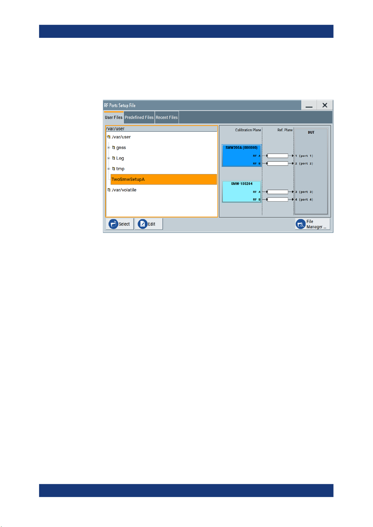
4. Select "Setup". The "RF Ports Setup File" dialog is opened.
RF Ports Alignment at the SMWs
How to Use RF Ports Alignment at the primary Signal Generator
Figure 4-2: RF Ports Setup File > User Files
5. Under "User Files", select the setup file received from RFPAL.
The test setup is displayed and you have access to the setup settings.
6. Check the settings:
● Make sure at "Common Trigger" (right sidebar) that "Master" is selected.
Check the related configuration. Make sure that the displayed baseband triggering information complies with the physical cabling and the calibrated setup.
● Check the correction data at "RF Ports Alignment > Info > Calibration".
● At "RF Ports Setup Info > Setup Overview", make sure that the current LO cou-
pling indication complies with the physical cabling and the calibrated setup.
41User Manual 1179.1912.02 ─ 01

R&S®RFPAL, R&S®SMW-K545
Figure 4-3: RF Ports Setup Info > Setup Overview
RF Ports Alignment at the SMWs
RF Ports Alignment Configuration and Settings
7. Back in the "RF Ports Alignment" view, click "Align" to synchronize the signal generators via multi-instrument trigger signal.
8. Select "On" for "RF Ports Alignment > State" to activate the RF ports alignment.
All instruments in the setup are triggered simultaneously. Calibration files and correction data are automatically applied during test execution.
4.2 RF Ports Alignment Configuration and Settings
Access:
► Select "System Configuration > Multi Instrument > RF Ports Alignment".
Settings:
● General Settings..................................................................................................... 43
● RF Ports Setup Info.................................................................................................46
● RF Ports Setup File Settings...................................................................................55
● Additional S-Parameter Files Settings.................................................................... 57
42User Manual 1179.1912.02 ─ 01

R&S®RFPAL, R&S®SMW-K545
4.2.1 General Settings
RF Ports Alignment at the SMWs
RF Ports Alignment Configuration and Settings
Figure 4-4: Multi Instrument > RF Ports Alignment
State..............................................................................................................................43
Setup.............................................................................................................................44
Info................................................................................................................................ 44
Test Setup..................................................................................................................... 44
Align.............................................................................................................................. 45
Status............................................................................................................................46
Error History..................................................................................................................46
State
Activates the RF ports alignment function. Setup files with correction data are transferred to the secondary instruments. The following configurations are automatically set.
Correction data is applied during signal generation using these configurations.
●
"RF":
– "Attenuator > Mode = Auto"
– "ALC > Mode = Off (Table)" and "ALC > Driver Amplifier = Auto"
– "UCOR > State = Off"
– "LO Coupling > Mode" = "Internal" or "A Internal & A->B Coupled"
– "LO Coupling > Out State = B On"; otherwise "Out State = Off"
●
"I/Q Mod > Frequency Response":
– "General > Optimization Mode = High Quality Table"
– "General > Optimization Bandwidth = Auto"
– "User Defined Corrections > State = On"
●
"System Configuration > Multi Instrument > Common Trigger":
– "State = On"
– "Multi Instrument Trigger = Master" on the primary instrument,
"Multi Instrument Trigger = Slave" on the secondary instruments
43User Manual 1179.1912.02 ─ 01

R&S®RFPAL, R&S®SMW-K545
●
"System Configuration > Multi Instrument > RF Ports Alignment > RF Ports Setup
Info":
– "Calibration > LO Coupling = Active"
– "Setup Overview > REF Configuration > Signal Source" = "Master" or "Exter-
nal"
– "Setup Overview > LO Configuration > Signal Source" = "Master" or "External"
– "Setup Overview > Wiring Constellation" = "Daisy Chain" or "Star"
Remote command:
:SCONfiguration:RFALignment:STATe on page 63
Setup
Accesses the "Setup File" dialog, that is the standard instrument function for saving
and loading setup files. The provided navigation possibilities in the dialog are selfexplanatory.
The filename and the directory in which the settings are saved are user-definable; the
file extension is predefined.
The setup file (*.rfsa) is an archive file containing setup description file (*.xml), the
RF port correction files (*.rfcor), the frequency response correction files
(*.rfresp) and the S-parameter files (*.snp). It is created automatically during calibration by RFPAL and can be loaded only in the primary instrument. Do not create
or modify setup files manually.
On recall, the instrument checks if the current instrument is the reference instrument
used during calibration with RFPAL. The dialog also displays the wiring diagram of the
selected setup. If the setup file is loaded in a different instrument, a setting conflict
appears.
The setup files in the secondary instruments are distributed by the primary instrument
and loaded in the secondaries automatically.
Remote command:
:SCONfiguration:RFALignment:SETup:PREDefined:CATalog? on page 61
:SCONfiguration:RFALignment:SETup:FILE:PREDefined on page 61
:SCONfiguration:RFALignment:SETup:CATalog? on page 62
:SCONfiguration:RFALignment:SETup:FILE on page 62
RF Ports Alignment at the SMWs
RF Ports Alignment Configuration and Settings
Info
Accesses the "RF Ports Setup Info" dialog that displays summary information on the
configured settings, see Chapter 4.2.2, "RF Ports Setup Info", on page 46.
Test Setup
Displays the cabling diagram fo the current setup.
The diagram is interactive. Click an element to access further settings.
Indicated are:
44User Manual 1179.1912.02 ─ 01

R&S®RFPAL, R&S®SMW-K545
Primary instrument
Secondary instrument(s)
RF Ports Alignment at the SMWs
RF Ports Alignment Configuration and Settings
The primary instrument, incl. alias name, serial number and number
of RF outputs.
The primary instrument is the upper most instrument displayed in
dark blue color. Click the block to open a dialog with its "Hostname /
IP Address" and for quick access to the RF Port Setup File Editor dialog ("Edit Setup").
The secondary instruments, incl. their remote connection status, alias
name, serial number and number of RF outputs.
Click the block to open a dialog with information on the "Hostname /
IP Address", "Remote Status" and for quick access to the RF Port
Setup File Editor dialog ("Edit Setup").
Figure 4-5: Secondary instrument dialog
S-parameter files
Indicates if and how many S-parameter files are loaded.
Figure 4-6: Additional S-Parameter Files dialog
DUT
DUT, incl. the RF ports designation, as configured in the RF Port
Setup File Editor dialog.
Align
Sends the multi-instrument trigger signal to all instruments to synchronize the basebands of the instruments if a valid setup is loaded ("RF Ports Alignment > Setup") and
the "RF Ports Alignment > State" is "On".
Remote command:
:SCONfiguration:RFALignment:ALIGn on page 63
45User Manual 1179.1912.02 ─ 01

R&S®RFPAL, R&S®SMW-K545
Status
Retrieves and displays information on the internal compensation status and the connected secondary instruments.
"No Setup"
Invalid Setup
"Not Active"
"Not Aligned"
"Aligned"
"Error"
"Warning"
A warning icon in the task bar indicates the erroneous situation.
Remote command:
:SCONfiguration:RFALignment:SETup:STATus? on page 62
RF Ports Alignment at the SMWs
RF Ports Alignment Configuration and Settings
A setup file has not been loaded.
Possible causes:
●
The loaded setup file has been removed.
●
The setup file is invalid (RF ports are not configured).
●
Mismatch between the setup and the physical instrument (the
setup is loaded in an instrument that is not the primary instrument).
The setup file is loaded but "RF Ports Alignment > State = Off".
Indicates one of the following situations:
●
Setup is loaded and "RF Ports Alignment > State = On", system is
not triggered
Execute "Align" to send the multi-instrument trigger signal to all
instruments to synchronize the basebands of the instruments.
●
Setup is loaded and active but frequency value is changed (in primary or in the secondary instrument).
The instrument with changed frequency value waits for trigger
event.
The setup is aligned and ready for operation.
Settings conflict or missing connection to secondary instruments.
Indicates the following situations:
●
Selected frequency or PEP value outside of the calibrated range.
●
Temperature deviation (Temperature Offset to Last Calibration is
greater than +/- 3K)
●
Internal adjustment was performed since last calibration.
●
"LO Coupling = On" but the secondary instrument cannot be
synchronized.
Error History
Indicates the status of the alignment process.
4.2.2 RF Ports Setup Info
Access:
1. Select "System Configuration > Multi Instrument > RF Ports Alignment".
2. Select "Setup > User files > <... .rfsa > > Select".
46User Manual 1179.1912.02 ─ 01

R&S®RFPAL, R&S®SMW-K545
3. Select "RF Ports Alignment" > "Info".
● Calibration Settings.................................................................................................47
● Current Corrections Settings...................................................................................50
● Setup Overview.......................................................................................................52
4.2.2.1 Calibration Settings
Access:
► Select "RF Ports Alignment > Info" > "Calibration".
RF Ports Alignment at the SMWs
RF Ports Alignment Configuration and Settings
Figure 4-7: RF Ports Setup Info > Calibration
This dialog displays summary information on the calibration data as retrieved from
the setup file.
Settings:
Calibration Date/Time....................................................................................................47
Calibrated Parameters.................................................................................................. 48
Time since Last Calibration...........................................................................................48
Temperature Offset to Last Calibration..........................................................................48
Frequency/PEP Control................................................................................................ 48
└ Mode...............................................................................................................48
└ Frequency Range/PEP Range........................................................................48
└ Frequency Step/PEP Step..............................................................................49
└ Frequency Values/PEP Values....................................................................... 49
└ LO Coupling....................................................................................................49
Calibration Date/Time
Indicates the date and time the calibration described in the loaded setup file is performed.
47User Manual 1179.1912.02 ─ 01

R&S®RFPAL, R&S®SMW-K545
Remote command:
:SCONfiguration:RFALignment:SETup:INFO:CALibration:DATE?
on page 64
:SCONfiguration:RFALignment:SETup:INFO:CALibration:TIME?
on page 64
Calibrated Parameters
Summary information on the major calibrated parameters.
Remote command:
:SCONfiguration:RFALignment:SETup:INFO:CALibration:PARameters?
on page 65
Time since Last Calibration
Indicates the elapsed time since the moment the calibration described in the loaded
setup file is performed.
Remote command:
:SCONfiguration:RFALignment:SETup:INFO:CALibration:AGE?
on page 64
RF Ports Alignment at the SMWs
RF Ports Alignment Configuration and Settings
Temperature Offset to Last Calibration
Indicates the difference in temperature since the moment the calibration described in
the loaded setup file is performed.
The indication is color coded; if the temperature deviation exceeds +/- 3K, the value is
displayed in red.
Remote command:
:SCONfiguration:RFALignment:SETup:INFO:CALibration:TEMPerature:
OFFSet? on page 65
Frequency/PEP Control
Comprises the frequency and PEP-related settings.
The displayed values resemble the values you have set during the calibration process.
Mode ← Frequency/PEP Control
Indicates the method used to define the calibrated frequency and PEP ranges.
"Range"
"List"
Remote command:
:SCONfiguration:RFALignment:SETup:INFO:CALibration:FREQuency:
MODE? on page 65
:SCONfiguration:RFALignment:SETup:INFO:CALibration:POWer:MODE?
on page 65
By the min and max values of the range.
As a sequence of discrete frequency values.
See Frequency Values/PEP Values.
Consider that greater number of calibration points leads to longer calibration time.
Frequency Range/PEP Range ← Frequency/PEP Control
Indicates the frequency and PEP ranges the calibrated values apply for.
48User Manual 1179.1912.02 ─ 01

R&S®RFPAL, R&S®SMW-K545
This value is displayed if "Mode = Range" is used during the calibration, where the
range is defined by the min and max values.
Remote command:
:SCONfiguration:RFALignment:SETup:INFO:CALibration:FREQuency:
RANGe:LOWer? on page 66
:SCONfiguration:RFALignment:SETup:INFO:CALibration:FREQuency:
RANGe:UPPer? on page 66
:SCONfiguration:RFALignment:SETup:INFO:CALibration:POWer:RANGe:
LOWer? on page 66
:SCONfiguration:RFALignment:SETup:INFO:CALibration:POWer:RANGe:
UPPer? on page 66
Frequency Step/PEP Step ← Frequency/PEP Control
This value is displayed if "Mode = Range" is used during the calibration. It indicates the
frequency/PEP step size that is used to define the frequency and level values to be
calibrated with the range, defined with the min and max values.
Remote command:
:SCONfiguration:RFALignment:SETup:INFO:CALibration:FREQuency:
STEP? on page 67
:SCONfiguration:RFALignment:SETup:INFO:CALibration:POWer:STEP?
on page 67
RF Ports Alignment at the SMWs
RF Ports Alignment Configuration and Settings
Frequency Values/PEP Values ← Frequency/PEP Control
This value is displayed if "Mode = List" is used during the calibration.
It indicates the calibrated values, that are defined as a sequence of comma-separated
discrete values in the required units.
Remote command:
:SCONfiguration:RFALignment:SETup:INFO:CALibration:FREQuency:
LIST:VALues? on page 66
:SCONfiguration:RFALignment:SETup:INFO:CALibration:POWer:LIST:
VALues? on page 66
LO Coupling ← Frequency/PEP Control
Indicates whether the instruments use a common local oscillator (LO) signal or not.
"Active"
All instruments are connected to the same LO reference frequency.
"Inactive"
Each instrument uses its own local oscillator.
Remote command:
:SCONfiguration:RFALignment:SETup:INFO:CALibration:LOCoupling?
on page 67
49User Manual 1179.1912.02 ─ 01
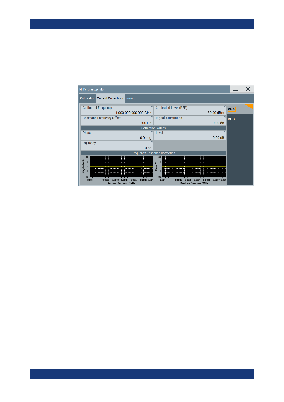
R&S®RFPAL, R&S®SMW-K545
4.2.2.2 Current Corrections Settings
Access:
► Select "RF Ports Alignment > Info" > "Current Corrections".
RF Ports Alignment at the SMWs
RF Ports Alignment Configuration and Settings
Figure 4-8: RF Ports Setup Info > Current Corrections
This dialog displays summary information on the current correction values per RF
path.
Settings:
Calibrated Frequency....................................................................................................50
Calibrated Level (PEP)..................................................................................................50
Baseband Frequency Offset..........................................................................................51
Digital Attenuation.........................................................................................................51
Correction Values..........................................................................................................51
└ Phase..............................................................................................................51
└ Level............................................................................................................... 51
└ I/Q Delay.........................................................................................................51
Frequency Response Correction.................................................................................. 51
Calibrated Frequency
Indicates the frequency f
the calibration data is valid for.
Cal
This is the value you have set as RF frequency during the calibration process.
Remote command:
:SOURce<hw>:RFALignment:CALibrated:FREQuency? on page 69
Calibrated Level (PEP)
Indicates the level P
Cal
the calibration data is valid for.
50User Manual 1179.1912.02 ─ 01

R&S®RFPAL, R&S®SMW-K545
Remote command:
:SOURce<hw>:RFALignment:CALibrated:POWer:PEP? on page 69
Baseband Frequency Offset
Indicates the applied baseband frequency offset f
between the current frequency f
f
("Calibrated Frequency").
Cal
Remote command:
:SOURce<hw>:RFALignment:FOFFset? on page 69
Digital Attenuation
Indicates the applied digital attenuation P
the current level P
Level").
Remote command:
:SOURce<hw>:RFALignment:DATTenuation? on page 69
Correction Values
Displays the correction values retrieved from the S-parameter files and used for compensation of the complex frequency response of the signal.
RF Ports Alignment at the SMWs
RF Ports Alignment Configuration and Settings
, calculated as the difference
BB Offset
("Status bar > Freq") and the calibrated frequency
RF Out
, calculated as the difference between
Dig Att
("Status bar > Level") and the calibrated level P
RF Out
("Calibrated
Cal
Phase ← Correction Values
Indicates the delta phase applied for compensation of the frequency response of the
signal.
The value is retrieved from the S-parameter files.
Remote command:
:SOURce<hw>:RFALignment:CORRection:PHASe? on page 70
Level ← Correction Values
Indicates the level correction applied to the signal of the selected path.
A level correction is required if a mismatch between the PEP values in the paths are
detected.
The value is retrieved from the S-parameter files.
Remote command:
:SOURce<hw>:RFALignment:CORRection:LEVel? on page 70
I/Q Delay ← Correction Values
Indicates the I/Q delay applied for compensation of the frequency response of the signal.
The value is retrieved from the S-parameter files.
Remote command:
:SOURce<hw>:RFALignment:CORRection:IQDelay? on page 70
Frequency Response Correction
Graphical representation of magnitude and phase variations of the currently used compensation filter over the available baseband bandwidth.
51User Manual 1179.1912.02 ─ 01

R&S®RFPAL, R&S®SMW-K545
4.2.2.3 Setup Overview
Access:
► Select "RF Ports Alignment > Info" > "Setup Overview".
RF Ports Alignment at the SMWs
RF Ports Alignment Configuration and Settings
Figure 4-9: RF Ports Setup Info > Setup Overview
This dialog displays the wiring diagram of the setup. The displayed information
resembles the setup displayed in the "RF Ports Alignment" dialog.
See "Test Setup" on page 44.
Ref Configuration > Signal Source................................................................................52
LO Configuration > Signal Source.................................................................................52
LO Configuration > Wiring Constellation.......................................................................53
Test Setup..................................................................................................................... 54
Ref Configuration > Signal Source
Indicates if the current instrument uses its own or an external reference signal.
"Master"
The instrument uses its reference signal and provides it to the other
instruments.
"External"
The instrument uses an external reference frequency source, for
example from other R&S SMW (the one with "Ref Configuration" >
"Signal Source = Master") or from R&S®SMA100B.
Remote command:
:SCONfiguration:RFALignment:SETup:INFO:WIRing:REF:SOURce?
on page 68
LO Configuration > Signal Source
Indicates if the current instrument uses its own or an external LO signal.
52User Manual 1179.1912.02 ─ 01

R&S®RFPAL, R&S®SMW-K545
"Intern (Master Instrument)"
"External Instrument"
Remote command:
:SCONfiguration:RFALignment:SETup:INFO:WIRing:LO:SOURce?
on page 68
RF Ports Alignment at the SMWs
RF Ports Alignment Configuration and Settings
The instrument uses its own LO frequency.
In a two-path instruments, the LOs of the two signal paths are coupled, where the LO signal of the first path is fed to the LO of the second one.
The block diagram indicates this connection, too.
The instrument acts as a secondary one regarding the LO frequency.
It receives the LO frequency from the instrument that acts as an LO
source in the setup.
The external LO signal is fed at the first signal path.
In a two-path instruments, the LOs of the two signal paths are coupled, where the LO signal of the first path is fed to the LO of the second one.
The block diagram indicates this connection, too.
LO Configuration > Wiring Constellation
Indicates the connection method used to distribute the LO frequency signal.
"Daisy Chain"
A connection scheme in which instruments are connected together in
sequence, i.e. an output of the first one is the connected to an input
of the second one, etc.
Figure 4-10: Example: Daisy chain connection for distributing the LO signal (sim-
* = I/Q, LAN etc. connections are not shown
Master = Instrument acting as LO signal source
Salve = One or more cascaded instruments, receiving (and forwarding) the
LO IN, LO OUT = LO connectors
RF = Signal output
plified)*
LO signal
53User Manual 1179.1912.02 ─ 01

R&S®RFPAL, R&S®SMW-K545
RF Ports Alignment at the SMWs
RF Ports Alignment Configuration and Settings
"Star"
A connection scheme for several instruments that consists of one
central instrument and several other instruments, all connected to the
central one.
Figure 4-11: Example: Star connection for distributing the LO signal (simplified)*
* = I/Q, LAN etc. connections are not shown
The LO signal of the primary instrument or from an external LO
source is split with a power combiner or splitter and fed to the secondary instruments.
Remote command:
:SCONfiguration:RFALignment:SETup:INFO:WIRing:LO:CONStellation?
on page 67
Test Setup
Displays the cabling diagram fo the current setup.
The diagram is interactive. Click an element to access further settings.
Indicated are:
Primary instrument
The primary instrument, incl. alias name, serial number and number
of RF outputs.
The primary instrument is the upper most instrument displayed in
dark blue color. Click the block to open a dialog with its "Hostname /
IP Address" and for quick access to the RF Port Setup File Editor dialog ("Edit Setup").
Secondary instrument(s)
The secondary instruments, incl. their remote connection status, alias
name, serial number and number of RF outputs.
Click the block to open a dialog with information on the "Hostname /
IP Address", "Remote Status" and for quick access to the RF Port
Setup File Editor dialog ("Edit Setup").
Figure 4-12: Secondary instrument dialog
54User Manual 1179.1912.02 ─ 01
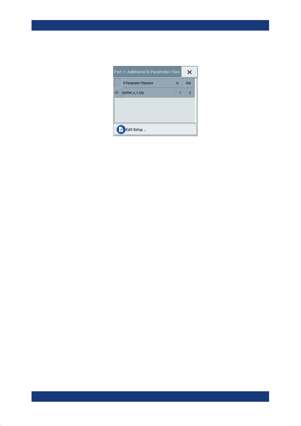
R&S®RFPAL, R&S®SMW-K545
S-parameter files
RF Ports Alignment at the SMWs
RF Ports Alignment Configuration and Settings
Indicates if and how many S-parameter files are loaded.
Figure 4-13: Additional S-Parameter Files dialog
DUT
DUT, incl. the RF ports designation, as configured in the RF Port
Setup File Editor dialog.
4.2.3 RF Ports Setup File Settings
Access:
1. Select "System Configuration > Multi Instrument > RF Ports Alignment" > "Setup".
2. Select a setup file and select "Edit".
The setup file (*.rfsa) is an archive file containing setup description file (*.xml),
the RF port correction files (*.rfcor), the frequency response correction files
(*.rfresp) and the S-parameter files (*.snp). Setup files are created automatically during the calibration process.
Do not create or edit setup files manually.
The "RF Ports Setup File Editor" dialog opens.
55User Manual 1179.1912.02 ─ 01

R&S®RFPAL, R&S®SMW-K545
Figure 4-14: RF Ports Setup File Editor
RF Ports Alignment at the SMWs
RF Ports Alignment Configuration and Settings
The dialog displays an overview information on the following:
● Configured ports including user-defined port names
● The physical instruments on that the ports are located
● The filename of the files with calibration data
● If S-Parameter files are used during the calibration or loaded afterwards, the fil-
enames of these files.
The "RF Ports Setup File Editor" dialog is the central point to reconfigure and control your setup. Here, you can rename ports, add, remove or exchange S-parameter files, retrieve information on connected external instruments, and save your settings in a loadable setup file.
RF port table................................................................................................................. 56
└ Port Name.......................................................................................................56
└ RF Source.......................................................................................................56
└ Hostname / IP Address...................................................................................56
└ Remote Status................................................................................................ 57
└ Additional S-Parameters Files........................................................................ 57
Save Setup .../Save Setup as ...................................................................................... 57
RF port table
Represents the RF ports configuration; there is one table row per RF port.
Port Name ← RF port table
Add an alias name for the RF port.
RF Source ← RF port table
Indicates the physical instrument which the RF port belongs to.
Hostname / IP Address ← RF port table
Displays/sets the IP address or hostname of the connected external instrument.
56User Manual 1179.1912.02 ─ 01

R&S®RFPAL, R&S®SMW-K545
Remote Status ← RF port table
Indicates the remote connection status.
and yellow
background
Additional S-Parameters Files ← RF port table
Indicates the filename of the S-Parameter files used during the calibration process or
the S-Parameter files loaded subsequently.
During calibration, you may load S-Parameter files which describe the cables between
the signal generator and the network analyzer. In this case, the correction data for the
setup is calculated so that it excludes the correction values listed in the S-Parameter
files. This allows you to exchange the S-Parameter files subsequently if you, for example, use different cables to connect the DUT to the outputs of the signal generator.
Click the filename to retrieve details on the loaded files or to select a different file, see
Chapter 4.2.4, "Additional S-Parameter Files Settings", on page 57.
RF Ports Alignment at the SMWs
RF Ports Alignment Configuration and Settings
The RF port belongs to a secondary instrument; the remote connection to the secondary instrument can be established.
The remote connection is active during the time the correction files
are transferred to the secondary instruments.
The term secondary instrument describes a signal generator connected in a primary-secondary mode and receiving the multi-instrument trigger from the primary instrument (see "System Configuration
> Multi Instrument > Common Trigger > Multi Instrument Trigger =
Slave")
At least one of the secondary instruments cannot be reached, that is
the remote connection to it cannot be established.
Check the "Hostname / IP Address" of the secondary instrument and
select "Refresh" to check the status.
Save Setup .../Save Setup as ...
Saves the setup configuration in a file.
The "*" symbol behind the filename in the dialog header indicates unsaved settings. It
appears whenever you change any of the settings in the dialog.
To overwrite the current file, select "Save Setup ... ".
To retain the setup file content, select "Save Setup as ...".
4.2.4 Additional S-Parameter Files Settings
Access:
1. Select "System Configuration > Multi Instrument > RF Ports Alignment" > "Setup".
2. Select a setup file and select "Edit".
57User Manual 1179.1912.02 ─ 01
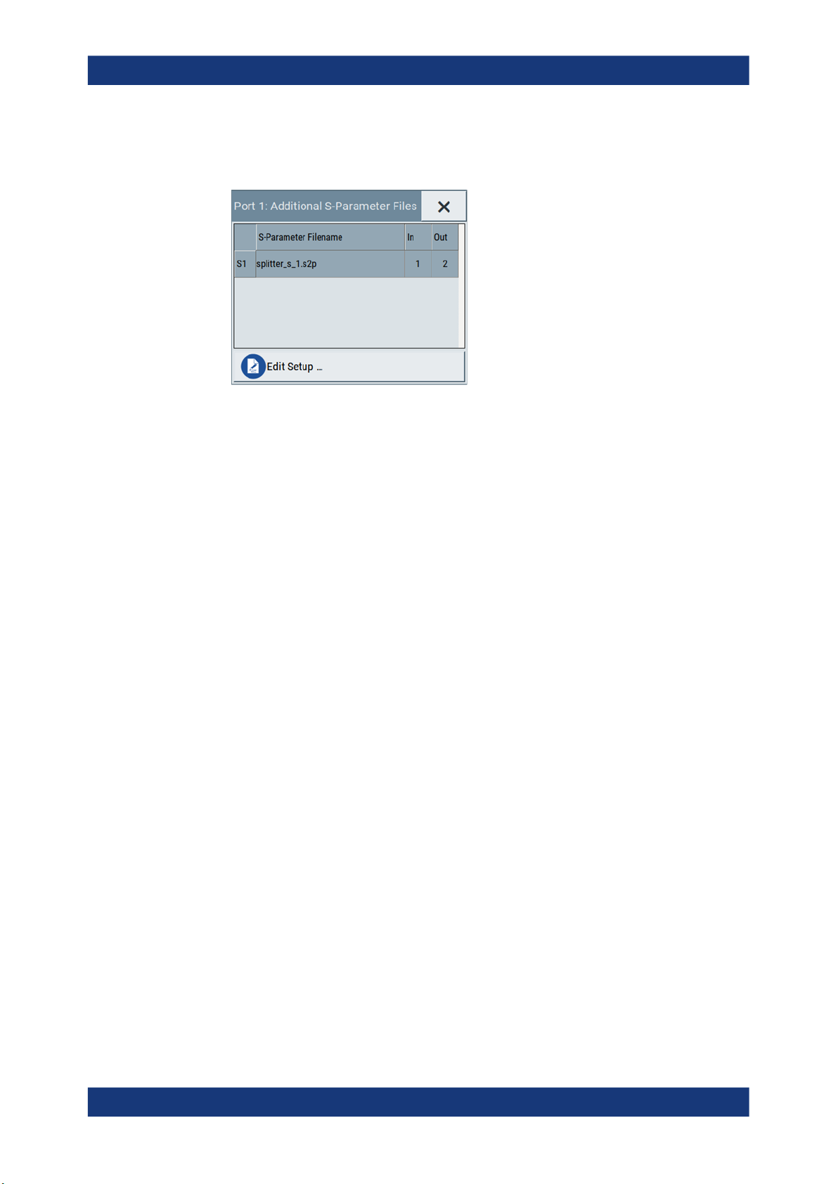
R&S®RFPAL, R&S®SMW-K545
3. Select "RF Ports / Instruments > RF ports table" > "Additional S-Parameter
Files".
In this dialog, you can load S-parameter files to compensate for exchanged cables
or other components.
Settings:
RF Ports Alignment at the SMWs
Remote Control Commands
Add S-Parameter File....................................................................................................58
S-Parameter Filename..................................................................................................58
In/Out............................................................................................................................ 58
Delete............................................................................................................................58
Add S-Parameter File
Appends a row in the table with S-parameter files.
S-Parameter Filename
Indicates the filename of the loaded file.
Select the filed to open the standard "File Select" dialog for selecting and loading S-
parameters (Touchstone) files. S-parameters files are files with predefined extension
(*.s<n>p) and file format.
Use the standard "File Manager" function to transfer external data lists to the instrument.
In/Out
Sets the origin and destination ports, i.e. the port number from that the signal is coming
and the port to that it is going. Use this parameter to change the orientation of the signal chain.
Delete
Removes the selected table row and the S-parameter file.
4.3 Remote Control Commands
The following commands are required to perform signal generation with the option
R&S SMW-K545 in a remote environment. We assume that the R&S SMW has already
58User Manual 1179.1912.02 ─ 01
R&S®RFPAL, R&S®SMW-K545
been set up for remote operation in a network as described in the R&S SMW documentation. A knowledge about the remote control operation and the SCPI command
syntax are assumed.
Conventions used in SCPI command descriptions
For a description of the conventions used in the remote command descriptions, see
section "Remote Control Commands" in the R&S SMW user manual.
Common Suffixes
The following common suffixes are used in the remote commands:
Suffix Value range Description
RF Ports Alignment at the SMWs
Remote Control Commands
SOURce<hw>
[1] to 4 Available baseband signals
The following commands specific to the R&S SMW-K545 option are described here:
● Programming Examples..........................................................................................59
● General Commands................................................................................................61
● RF Port Setup Info Commands...............................................................................63
● Current Corrections Commands............................................................................. 68
4.3.1 Programming Examples
This description provides simple programming examples. The purpose of the examples
is to present all commands for a given task. In real applications, one would rather
reduce the examples to an appropriate subset of commands.
The programming examples have been tested with a software tool which provides an
environment for the development and execution of remote tests. To keep the example
as simple as possible, only the "clean" SCPI syntax elements are reported. Non-executable command lines (e.g. comments) start with two // characters.
At the beginning of the most remote control program, an instrument (p)reset is recommended to set the instrument to a definite state. The commands *RST and
SYSTem:PRESet are equivalent for this purpose. *CLS also resets the status registers
and clears the output buffer.
59User Manual 1179.1912.02 ─ 01

R&S®RFPAL, R&S®SMW-K545
Example: Loading and activating setup files
This example uses the predefined demo setup file.
// SCONfiguration:RFALignment:SETup:CATalog?
// SCONfiguration:RFALignment:SETup:FILE "/var/user/RfPortsSetup/setup"
SCONfiguration:RFALignment:SETup:PREDefined:CATalog?
// demo
SCONfiguration:RFALignment:SETup:FILE:PREDefined "demo"
SCONfiguration:RFALignment:SETup:STATus?
// NALign
SCONfiguration:RFALignment:ALIGn
SCONfiguration:RFALignment:SETup:STATus?
// ALIGned
SCONfiguration:RFALignment:STATe 1
Example: Retrieving details on the calibrated values
This example uses the predefined demo setup file.
SCONfiguration:RFALignment:SETup:PREDefined:CATalog?
// demo
SCONfiguration:RFALignment:SETup:FILE:PREDefined "demo"
RF Ports Alignment at the SMWs
Remote Control Commands
SCONfiguration:RFALignment:SETup:INFO:CALibration:DATE?
// "2019-01-11"
SCONfiguration:RFALignment:SETup:INFO:CALibration:TIME?
// "08:15:37 "
SCONfiguration:RFALignment:SETup:INFO:CALibration:PARameters?
// "Level,Phase,Time"
SCONfiguration:RFALignment:SETup:INFO:CALibration:AGE?
// 52
SCONfiguration:RFALignment:SETup:INFO:CALibration:TEMPerature:OFFSet?
// 0
SCONfiguration:RFALignment:SETup:INFO:WIRing:LO:SOURce?
// MAST
SCONfiguration:RFALignment:SETup:INFO:WIRing:LO:CONStellation?
// DCH
SCONfiguration:RFALignment:SETup:INFO:WIRing:REF:SOURce?
// MAST
SCONfiguration:RFALignment:SETup:INFO:CALibration:FREQuency:MODE?
// RANG
SCONfiguration:RFALignment:SETup:INFO:CALibration:FREQuency:RANGe:LOWer?
// 1000000000
SCONfiguration:RFALignment:SETup:INFO:CALibration:FREQuency:RANGe:UPPer?
// 6000000000
SCONfiguration:RFALignment:SETup:INFO:CALibration:FREQuency:STEP?
// 500000000
SCONfiguration:RFALignment:SETup:INFO:CALibration:LOCoupling?
// ACT
SCONfiguration:RFALignment:SETup:INFO:CALibration:POWer:MODE?
60User Manual 1179.1912.02 ─ 01

R&S®RFPAL, R&S®SMW-K545
// RANG
SCONfiguration:RFALignment:SETup:INFO:CALibration:POWer:RANGe:LOWer?
// -10
SCONfiguration:RFALignment:SETup:INFO:CALibration:POWer:RANGe:UPPer?
// 0
SCONfiguration:RFALignment:SETup:INFO:CALibration:POWer:STEP?
// 10
SOURce1:RFALignment:CALibrated:FREQuency?
// 1000000000
SOURce1:RFALignment:CALibrated:POWer:PEP?
// -30
SOURce1:RFALignment:DATTenuation?
// 0
SOURce1:RFALignment:FOFFset
// 0
SOURce1:RFALignment:CORRection:IQDelay?
// 0
SOURce1:RFALignment:CORRection:LEVel?
// 0
SOURce1:RFALignment:CORRection:PHASe?
// 0
RF Ports Alignment at the SMWs
Remote Control Commands
4.3.2 General Commands
:SCONfiguration:RFALignment:SETup:PREDefined:CATalog?..............................................61
:SCONfiguration:RFALignment:SETup:FILE:PREDefined.....................................................61
:SCONfiguration:RFALignment:SETup:CATalog?.................................................................62
:SCONfiguration:RFALignment:SETup:FILE........................................................................62
:SCONfiguration:RFALignment:SETup:STATus?..................................................................62
:SCONfiguration:RFALignment:ALIGn................................................................................63
:SCONfiguration:RFALignment:STATe................................................................................63
:SCONfiguration:RFALignment:SETup:PREDefined:CATalog?
Queries the names of the existing predefined setup files.
Only files with extension *.rfsa are listed.
Example:
Usage: Query only
Manual operation: See "Setup" on page 44
:SCONfiguration:RFALignment:SETup:FILE:PREDefined <Filename>
Loads the selected predefined file.
See Example "Loading and activating setup files" on page 60.
61User Manual 1179.1912.02 ─ 01

R&S®RFPAL, R&S®SMW-K545
Setting parameters:
<Filename> "<filename>"
Example: See Example "Loading and activating setup files" on page 60.
Usage: Setting only
Manual operation: See "Setup" on page 44
:SCONfiguration:RFALignment:SETup:CATalog?
Queries the names of the existing setup files in the default directory.
Per default, the instrument stores user-defined files in the /var/user/ directory. Use
the command MMEM:CDIRectory to change the default directory to the currently used
one.
RF Ports Alignment at the SMWs
Remote Control Commands
File extension can be omitted.
Query the filenames of predefined setup files with the command :SCONfiguration:RFALignment:SETup:
PREDefined:CATalog?.
Only files with extension *.rfsa are listed.
Example:
Usage: Query only
Manual operation: See "Setup" on page 44
:SCONfiguration:RFALignment:SETup:FILE <SetupFile>
Loads the selected file from the default or the specified directory. Loaded are files with
extension *.rfsa.
Parameters:
<SetupFile> "<filename>"
Example: See Example "Loading and activating setup files" on page 60.
Manual operation: See "Setup" on page 44
:SCONfiguration:RFALignment:SETup:STATus?
See Example "Loading and activating setup files" on page 60.
Filename or complete file path; file extension can be omitted.
Query the filenames of existing setup files with the command :
SCONfiguration:RFALignment:SETup:CATalog?.
Queries information on the internal compensation status and the connected secondary
instruments.
Return values:
<SetupStatus> NALign | ALIGned | ERRor | WARNing | INACtive | NOSetup |
INValid
NOSetup = Setup is not loaded
62User Manual 1179.1912.02 ─ 01

R&S®RFPAL, R&S®SMW-K545
Example: See Example "Loading and activating setup files" on page 60.
Usage: Query only
Manual operation: See "Status" on page 46
:SCONfiguration:RFALignment:ALIGn
If a valid setup is loaded and RF ports alignment is enabled, sends the multi instrument
trigger signal to all instruments to synchonize the basebands of the instruments.
RF Ports Alignment at the SMWs
Remote Control Commands
INValid = Loaded setup does not match the current setup
INACtive = Setup loaded but RF port alignment not enabled
NALign = Setup is loaded but aligned not triggered
ALIGned | ERRor | WARNing = Setup is aligned, error,
warning
*RST: n.a. (factory preset)
Example:
See Example "Loading and activating setup files" on page 60.
Usage: Event
Manual operation: See "Align" on page 45
:SCONfiguration:RFALignment:STATe <State>
If a valid setup file is selected, applies the specified correction data.
Load the setup file with the command :SCONfiguration:RFALignment:SETup:
FILE.
Parameters:
<State> 0 | 1 | OFF | ON
*RST: n.a. (factory preset: 0)
Example: See Example "Loading and activating setup files" on page 60.
Manual operation: See "State" on page 43
4.3.3 RF Port Setup Info Commands
:SCONfiguration:RFALignment:SETup:INFO:CALibration:DATE?..........................................64
:SCONfiguration:RFALignment:SETup:INFO:CALibration:TIME?...........................................64
:SCONfiguration:RFALignment:SETup:INFO:CALibration:AGE?........................................... 64
:SCONfiguration:RFALignment:SETup:INFO:CALibration:TEMPerature:OFFSet?...................65
:SCONfiguration:RFALignment:SETup:INFO:CALibration:PARameters?................................ 65
:SCONfiguration:RFALignment:SETup:INFO:CALibration:FREQuency:MODE?......................65
:SCONfiguration:RFALignment:SETup:INFO:CALibration:POWer:MODE?............................. 65
:SCONfiguration:RFALignment:SETup:INFO:CALibration:FREQuency:LIST:VALues?............. 66
:SCONfiguration:RFALignment:SETup:INFO:CALibration:POWer:LIST:VALues?.................... 66
:SCONfiguration:RFALignment:SETup:INFO:CALibration:FREQuency:RANGe:LOWer?......... 66
:SCONfiguration:RFALignment:SETup:INFO:CALibration:FREQuency:RANGe:UPPer?.......... 66
63User Manual 1179.1912.02 ─ 01

R&S®RFPAL, R&S®SMW-K545
:SCONfiguration:RFALignment:SETup:INFO:CALibration:POWer:RANGe:LOWer?.................66
:SCONfiguration:RFALignment:SETup:INFO:CALibration:POWer:RANGe:UPPer?................. 66
:SCONfiguration:RFALignment:SETup:INFO:CALibration:FREQuency:STEP?....................... 67
:SCONfiguration:RFALignment:SETup:INFO:CALibration:POWer:STEP?.............................. 67
:SCONfiguration:RFALignment:SETup:INFO:CALibration:LOCoupling?................................. 67
:SCONfiguration:RFALignment:SETup:INFO:WIRing:LO:CONStellation?...............................67
:SCONfiguration:RFALignment:SETup:INFO:WIRing:LO:SOURce?.......................................68
:SCONfiguration:RFALignment:SETup:INFO:WIRing:REF:SOURce?.................................... 68
:SCONfiguration:RFALignment:SETup:INFO:CALibration:DATE?
Queries the time the calibration described in the loaded setup file is performed.
Return values:
<Date> string
Example: See Example "Retrieving details on the calibrated values"
Usage: Query only
RF Ports Alignment at the SMWs
Remote Control Commands
on page 60.
Manual operation: See "Calibration Date/Time" on page 47
:SCONfiguration:RFALignment:SETup:INFO:CALibration:TIME?
the date and time the calibration described in the loaded setup file is performed.
Return values:
<Time> string
Example: See Example "Retrieving details on the calibrated values"
on page 60.
Usage: Query only
Manual operation: See "Calibration Date/Time" on page 47
:SCONfiguration:RFALignment:SETup:INFO:CALibration:AGE?
Queries how many days are passed since the moment the calibration described in the
loaded setup file is performed.
Return values:
<Days> integer
Time since calibration in days
Example: See Example "Retrieving details on the calibrated values"
on page 60.
Usage: Query only
Manual operation: See "Time since Last Calibration" on page 48
64User Manual 1179.1912.02 ─ 01

R&S®RFPAL, R&S®SMW-K545
:SCONfiguration:RFALignment:SETup:INFO:CALibration:TEMPerature:OFFSet?
Queries the difference in temperature since the moment the calibration described in
the loaded setup file is performed.
Return values:
<TempOffset> float
Example: See Example "Retrieving details on the calibrated values"
Usage: Query only
Manual operation: See "Temperature Offset to Last Calibration" on page 48
:SCONfiguration:RFALignment:SETup:INFO:CALibration:PARameters?
Queries information on the major calibrated parameters.
Return values:
<CalibratedParam> string
RF Ports Alignment at the SMWs
Remote Control Commands
Increment: 0.01
on page 60.
Example: See Example "Retrieving details on the calibrated values"
on page 60.
Usage: Query only
Manual operation: See "Calibrated Parameters" on page 48
:SCONfiguration:RFALignment:SETup:INFO:CALibration:FREQuency:MODE?
:SCONfiguration:RFALignment:SETup:INFO:CALibration:POWer:MODE?
Queries the method used to defined the calibrated frequency and PEP ranges.
Return values:
<Mode> RANGe | LIST
RANGe
Range, see:
:SCONfiguration:RFALignment:SETup:INFO:
CALibration:FREQuency:RANGe:LOWer? on page 66
:SCONfiguration:RFALignment:SETup:INFO:
CALibration:FREQuency:RANGe:UPPer? on page 66
:SCONfiguration:RFALignment:SETup:INFO:
CALibration:FREQuency:STEP? on page 67
:SCONfiguration:RFALignment:SETup:INFO:
CALibration:POWer:RANGe:LOWer? on page 66
:SCONfiguration:RFALignment:SETup:INFO:
CALibration:POWer:RANGe:UPPer? on page 66
:SCONfiguration:RFALignment:SETup:INFO:
CALibration:POWer:STEP? on page 67
65User Manual 1179.1912.02 ─ 01

R&S®RFPAL, R&S®SMW-K545
Example: See Example "Retrieving details on the calibrated values"
Usage: Query only
Manual operation: See "Mode" on page 48
:SCONfiguration:RFALignment:SETup:INFO:CALibration:FREQuency:LIST:
VALues?
:SCONfiguration:RFALignment:SETup:INFO:CALibration:POWer:LIST:VALues?
Return values:
<ListOfValues> string
RF Ports Alignment at the SMWs
Remote Control Commands
LIST
List, see:
:SCONfiguration:RFALignment:SETup:INFO:
CALibration:FREQuency:LIST:VALues? on page 66
:SCONfiguration:RFALignment:SETup:INFO:
CALibration:POWer:LIST:VALues? on page 66
on page 60.
Example:
SCONfiguration:RFALignment:SETup:INFO:CALibration:LOCoupling?
// NACTive
SCONfiguration:RFALignment:SETup:INFO:CALibration:POWer:MODE?
// LIST
SCONfiguration:RFALignment:SETup:INFO:CALibration:POWer:LIST:VALues?
// -21,-15,-10
Usage: Query only
Manual operation: See "Frequency Values/PEP Values" on page 49
:SCONfiguration:RFALignment:SETup:INFO:CALibration:FREQuency:RANGe:
LOWer?
:SCONfiguration:RFALignment:SETup:INFO:CALibration:FREQuency:RANGe:
UPPer?
:SCONfiguration:RFALignment:SETup:INFO:CALibration:POWer:RANGe:
LOWer?
:SCONfiguration:RFALignment:SETup:INFO:CALibration:POWer:RANGe:UPPer?
Queries the min and max frequency and PEP values that define the calibrated range.
Return values:
<PEPmax> float
Increment: 0.01
Example: See Example "Retrieving details on the calibrated values"
on page 60.
Usage: Query only
Manual operation: See "Frequency Range/PEP Range" on page 48
66User Manual 1179.1912.02 ─ 01

R&S®RFPAL, R&S®SMW-K545
:SCONfiguration:RFALignment:SETup:INFO:CALibration:FREQuency:STEP?
:SCONfiguration:RFALignment:SETup:INFO:CALibration:POWer:STEP?
Queries the frequency/PEP step size with that the calibration values are selected from
the defined value range.
Return values:
<PEPstep> float
Example: See Example "Retrieving details on the calibrated values"
Usage: Query only
Manual operation: See "Frequency Step/PEP Step" on page 49
:SCONfiguration:RFALignment:SETup:INFO:CALibration:LOCoupling?
Queries whether the instruments use a common local oscillator (LO) signal or not.
RF Ports Alignment at the SMWs
Remote Control Commands
Increment: 0.01
on page 60.
Return values:
<State> ACTive | NACTive
ACTive
All instruments are connected to the same LO reference frequency.
NACTive
Each instrument uses its own local oscillator.
*RST: n.a. (factory preset)
Example: See Example "Retrieving details on the calibrated values"
on page 60.
Usage: Query only
Manual operation: See "LO Coupling" on page 49
:SCONfiguration:RFALignment:SETup:INFO:WIRing:LO:CONStellation?
Queries the connection method used to distribute the LO frequency signal.
Return values:
<Constellation> DCHain | STAR
DCHain
Daisy chain
STAR
Star
Example: See Example "Retrieving details on the calibrated values"
on page 60.
Usage: Query only
Manual operation: See "LO Configuration > Wiring Constellation" on page 53
67User Manual 1179.1912.02 ─ 01

R&S®RFPAL, R&S®SMW-K545
:SCONfiguration:RFALignment:SETup:INFO:WIRing:LO:SOURce?
Queries if the current instrument uses its own or an external LO signal.
Return values:
<Source> MASTer | EXTernal
Example: See Example "Retrieving details on the calibrated values"
Usage: Query only
RF Ports Alignment at the SMWs
Remote Control Commands
MASTern
The instrument uses its LO signal and provides it to the other
instruments.
EXTernal
The instrument uses an external LO signal, for example from
other R&S SMW (the one with
SCONfiguration:RFALignment:SETup:INFO:WIRing:
LO:SOURce MASTer).
on page 60.
Manual operation: See "LO Configuration > Signal Source" on page 52
:SCONfiguration:RFALignment:SETup:INFO:WIRing:REF:SOURce?
Queries if the current instrument uses its own or an external reference signal.
Return values:
<Source> MASTer | EXTernal
MASTer
The instrument uses its reference signal and provides it to the
other instruments.
EXTernal
The instrument uses an external reference frequency source, for
example from other R&S SMW (the one with
SCONfiguration:RFALignment:SETup:INFO:WIRing:
REF:SOURce MASTer) or from R&S®SMA100B.
Example: See Example "Retrieving details on the calibrated values"
on page 60.
Usage: Query only
Manual operation: See "Ref Configuration > Signal Source" on page 52
4.3.4 Current Corrections Commands
:SOURce<hw>:RFALignment:CALibrated:FREQuency?.......................................................69
:SOURce<hw>:RFALignment:CALibrated:POWer:PEP?...................................................... 69
:SOURce<hw>:RFALignment:FOFFset?.............................................................................69
:SOURce<hw>:RFALignment:DATTenuation?..................................................................... 69
68User Manual 1179.1912.02 ─ 01

R&S®RFPAL, R&S®SMW-K545
:SOURce<hw>:RFALignment:CORRection:PHASe?............................................................70
:SOURce<hw>:RFALignment:CORRection:LEVel?..............................................................70
:SOURce<hw>:RFALignment:CORRection:IQDelay?...........................................................70
:SOURce<hw>:RFALignment:CALibrated:FREQuency?
Queries the frequency for that the calibration data is valid.
Return values:
<CalibratedFreq> float
Example: See Example "Retrieving details on the calibrated values"
Usage: Query only
Manual operation: See "Calibrated Frequency" on page 50
:SOURce<hw>:RFALignment:CALibrated:POWer:PEP?
RF Ports Alignment at the SMWs
Remote Control Commands
Increment: 0.01
on page 60.
Queries the PEP for that the calibration data is valid.
Return values:
<PEP> float
Increment: 0.01
Example: See Example "Retrieving details on the calibrated values"
on page 60.
Usage: Query only
Manual operation: See "Calibrated Level (PEP)" on page 50
:SOURce<hw>:RFALignment:FOFFset?
Queries the applied baseband frequency offset.
Return values:
<BbFreqOffset> float
Increment: 0.01
Example: See Example "Retrieving details on the calibrated values"
on page 60.
Usage: Query only
Manual operation: See "Baseband Frequency Offset" on page 51
:SOURce<hw>:RFALignment:DATTenuation?
Queries the applied digital attenuation.
69User Manual 1179.1912.02 ─ 01

R&S®RFPAL, R&S®SMW-K545
Return values:
<Attenuation> float
Example: See Example "Retrieving details on the calibrated values"
Usage: Query only
Manual operation: See "Digital Attenuation" on page 51
:SOURce<hw>:RFALignment:CORRection:PHASe?
queries the delta phase applied for compensation of the frequency response of the signal.
Return values:
<Phase> float
RF Ports Alignment at the SMWs
Remote Control Commands
Increment: 0.01
on page 60.
Increment: 0.01
Example: See Example "Retrieving details on the calibrated values"
on page 60.
Usage: Query only
Manual operation: See "Phase" on page 51
:SOURce<hw>:RFALignment:CORRection:LEVel?
Queries the level correction applied to the signal of the selected path.
Return values:
<Level> float
Increment: 0.01
Example: See Example "Retrieving details on the calibrated values"
on page 60.
Usage: Query only
Manual operation: See "Level" on page 51
:SOURce<hw>:RFALignment:CORRection:IQDelay?
Queries the I/Q delay applied for compensation of the frequency response of the signal.
Return values:
<IQdelay> float
Increment: 1E-12
Example: See Example "Retrieving details on the calibrated values"
on page 60.
70User Manual 1179.1912.02 ─ 01

R&S®RFPAL, R&S®SMW-K545
Usage: Query only
Manual operation: See "I/Q Delay" on page 51
RF Ports Alignment at the SMWs
Remote Control Commands
71User Manual 1179.1912.02 ─ 01

R&S®RFPAL, R&S®SMW-K545
Annex
A Files and Data
A.1 Supported File Formats
The following file formats are supported.
Extension File type Description
Files and Data
S-Parameters (Touchstone) Files
*.rfsa
*.xml
*.rfcor
*.rfresp
*.s<n>p
Archive file containing the setup
description file, the RF port configuration files and the S-parameter files
Setup description file Files in proprietary file format, created
RF port correction files
frequency response correction files
Touchstone S-parameters files See Chapter A.2, "S-Parameters (Touch-
A.2 S-Parameters (Touchstone) Files
The R&S SMW can extract and apply scattering matrix corrections from S-parameters
data files. These data files are also known as Touchstone files and exist in two format
versions, V1.0 and V2.0.
Setup file (*.rfsa) are archive files in
proprietary file format.
They contain the setup description file
(*.xml), the RF port correction files
(*.rfcor), the frequency response correction files (*.rfresp) and the S-parameter files (*.snp).
Setup files are created automatically during the calibration process. Do not edit
setup files manually.
automatically during setup calibration.
The files are human-readable but should
not be created or edited manually.
stone) Files", on page 72.
R&S SMW-K545 supports Touchstone file format in version V1.0.
File extension
S-parameters files are files with predefined structure and file extension *.s<n>p,
where <n>:
●
Is an integer value and <n> ≥ 1
●
<n> = number of measured ports
●
<n>2 = number of S-parameters the file contains
72User Manual 1179.1912.02 ─ 01

R&S®RFPAL, R&S®SMW-K545
An *.s1p file, for example, contains a one-port measurement and one S-parameter
while the file *.s3p contains a three-port measurement and nine S-parameters.
The most meaningful S-parameter for the frequency response compensation is the
S21, because it characterizes the frequency response of a component.
S-parameters measurements are typically performed with a vector network analyzer,
like, for example, the R&S®ZNB.
File format
Touchstone files contain a header, a comment section, and the actual trace data.
The following is an extract of the file content of file created by the R&S®ZNB.
# HZ S RI R 50.00
! Rohde & Schwarz Vector Network Analyzer
! Rohde-Schwarz,ZNB8-4Port,1311601044100005,1.93.1.42
! Created: UTC 9/17/2013, 9:13:56 AM
! freq[Hz] re:S11 im:S11
1.000000000000000E5 -4.897128641605377E-1 3.767784312367439E-2
4.259950000000000E7 -5.450598597526550E-1 3.608805686235428E-2
...
Files and Data
S-Parameters (Touchstone) Files
# indicates the beginning of the header line. It is required at the top of file and consists
of the following data elements:
●
<Frequency unit>: HZ / KHZ / MHZ / GHZ, Rohde & Schwarz analyzers usually
use Hz.
●
<Data file type>: S for S-parameter files
●
<Data format>:
– RI = Re/Im
– MA = linear Magnitude-Phase
– DB = Mag-Phase in decibels
●
<Reference resistance>: specifies the impedance system underlying the trace
data, given as a real, positive resistance (default 50 Ω)
Comment lines start with the exclamation mark (!) and can contain any text used for
documentation of the trace data file. Any number of comment lines can be inserted
before or after the header line.
The following information is displayed in the comments section:
●
VNA identification (comment line 2 in above example)
●
Timestamp (comment line 3)
●
Port-specific renormalization information (comment lines 4ff, if applied)
●
Headings for included data tables (comment lines right above the data tables, starting with ! freq)
The trace data section corresponds to a set of single-ended S-parameters. It depends
on the number of ports and the data format.
73User Manual 1179.1912.02 ─ 01

R&S®RFPAL, R&S®SMW-K545
For real and imaginary values (<Data format> = RI) the trace data for each stimulus
frequency is arranged as indicated in the lowermost comment lines:
●
1-port files (*.s1p)
! freq[Hz] re:S11 im:S11
S11 can be replaced by any S-parameter.
Thus, the *.s1p format can contain an arbitrary data trace representing an Sparameter.
●
2-port files (*.s2p)
! freq[Hz] re:S11 im:S11 re:S21 im:S21 re:S12 im:S12 re:
S22 im:S22
(all values arranged in 1 line)
●
n-port files (*.snp), 2 < n ≤ 4
! freq[Hz] re:S11 im:S11 re:S12 im:S12 ... re:S1n im:S1n
! re:S21 im:S21 re:S22 im:S22 ... re:S2n im:S2n
! ...
! re:Sn1 im:Sn1 re:Sn2 im:Sn2 ... re:Snn im:Snn
(values arranged in n lines)
●
n-port files (*.snp), n > 4
! freq[Hz] re:S11 im:S11 ... re:S14 im:S14
! re:S15 im:S15 ...
! ...
! ... re:Snn im:Snn
(values arranged in m = ⌈n2/4⌉ lines, where the first —1 data lines contain exactly
four value pairs)
Files and Data
S-Parameters (Touchstone) Files
The stimulus frequencies are arranged in ascending order. For linear Magnitude-Phase
and Magnitude-Phase in decibels values (<Data format> = MA or DB), the trace data
the real and imaginary S-parameter values re:Sij im:Sij are replaced by
mag:Sij ang:Sij or db:Sij ang:Sij, respectively.
Cascading files
If several S-parameter files are loaded, they are cascaded. Each S-parameters file is
defined with its origin and destination ports. Thus, you can configure or reverse the orientation of the signal chain.
The first entry in the chain is the R&S SMW itself; it illustrates the chain orientation form R&S SMW toward the DUT.
74User Manual 1179.1912.02 ─ 01
 Loading...