


R&S®SMW-K130/-K355
OneWeb User-Defined Signal
Generation, OneWeb Reference
Signals
User Manual
(;ÜÇ>2)
1178571402
Version 08

This document describes the following software options:
●
R&S®SMW-K130 OneWeb User-Defined Signal Generation (1414.3788.xx)
●
R&S®SMW-K355 OneWeb Reference Signals (1414.3742.xx)
This manual describes firmware version FW 5.00.044.xx and later of the R&S®SMW200A.
© 2021 Rohde & Schwarz GmbH & Co. KG
Mühldorfstr. 15, 81671 München, Germany
Phone: +49 89 41 29 - 0
Email: info@rohde-schwarz.com
Internet: www.rohde-schwarz.com
Subject to change – data without tolerance limits is not binding.
R&S® is a registered trademark of Rohde & Schwarz GmbH & Co. KG.
Trade names are trademarks of the owners.
1178.5714.02 | Version 08 | R&S®SMW-K130/-K355
The following abbreviations are used throughout this manual: R&S®SMW200A is abbreviated as R&S SMW, R&S®WinIQSIM2 is
abbreviated as R&S WinIQSIM2; the license types 02/03/07/11/13/16/12 are abbreviated as xx.

R&S®SMW-K130/-K355
Contents
1 Welcome to the OneWeb option........................................................... 7
1.1 Accessing the OneWeb dialog.....................................................................................7
1.2 Documentation overview..............................................................................................7
1.2.1 Getting started manual....................................................................................................8
1.2.2 User manuals and help................................................................................................... 8
1.2.3 Tutorials...........................................................................................................................8
1.2.4 Service manual............................................................................................................... 8
1.2.5 Instrument security procedures.......................................................................................8
1.2.6 Printed safety instructions............................................................................................... 9
1.2.7 Data sheets and brochures............................................................................................. 9
1.2.8 Release notes and open source acknowledgment (OSA).............................................. 9
Contents
1.2.9 Application notes, application cards, white papers, etc...................................................9
1.3 Scope........................................................................................................................... 10
1.4 Notes on screenshots.................................................................................................10
2 About OneWeb option......................................................................... 11
2.1 Required options.........................................................................................................11
2.2 Provided reference signals........................................................................................ 11
3 Oneweb configuration and settings................................................... 17
3.1 General settings.......................................................................................................... 17
3.2 Predefined mode settings.......................................................................................... 19
3.3 User-defined mode settings.......................................................................................20
3.4 General downlink settings......................................................................................... 21
3.4.1 PDSCH scheduling settings.......................................................................................... 22
3.4.2 Physical settings........................................................................................................... 23
3.4.3 Cell-specific settings..................................................................................................... 25
3.4.4 Downlink signals settings.............................................................................................. 26
3.4.5 Antenna ports settings.................................................................................................. 27
3.5 Downlink frame configuration................................................................................... 29
3.5.1 General frame configuration settings............................................................................ 30
3.5.2 User configuration settings............................................................................................31
3.5.3 Subframe configuration settings....................................................................................34
3User Manual 1178.5714.02 ─ 08

R&S®SMW-K130/-K355
3.5.4 DL resource allocation table..........................................................................................35
3.5.5 PCFICH settings........................................................................................................... 38
3.5.6 PDCCH settings............................................................................................................ 40
3.5.7 DCI format configuration............................................................................................... 47
3.5.8 Enhanced PBCH and PDSCH settings......................................................................... 52
3.6 General uplink settings.............................................................................................. 57
3.6.1 UL carrier aggregation configuration.............................................................................57
3.6.2 UL physical settings...................................................................................................... 60
3.6.3 UL cell specific settings.................................................................................................62
3.6.4 Signals settings............................................................................................................. 64
3.6.5 PRACH settings............................................................................................................ 67
3.6.6 PUCCH structure.......................................................................................................... 70
3.7 Uplink frame configuration........................................................................................ 73
Contents
3.7.1 General scheduling configuration settings.................................................................... 73
3.7.2 Subframe configuration................................................................................................. 75
3.7.3 UL allocation table.........................................................................................................76
3.7.4 Enhanced PUSCH/PUACH settings............................................................................. 81
3.7.5 Enhanced PUCCH settings...........................................................................................88
3.8 User equipment configuration................................................................................... 94
3.8.1 Common settings.......................................................................................................... 94
3.8.2 Physical uplink shared channel/physical uplink aloha channel (PUSCH/PUACH)....... 96
3.8.3 Demodulation reference signal (DRS).......................................................................... 99
3.8.4 Sounding reference signal (SRS)................................................................................100
3.8.5 PRACH power ramping............................................................................................... 110
3.8.6 PRACH configuration...................................................................................................111
3.9 Trigger settings......................................................................................................... 113
3.10 Marker settings..........................................................................................................119
3.11 Clock settings............................................................................................................120
3.12 Filter/clipping/ARB settings..................................................................................... 122
3.12.1 Filter settings...............................................................................................................123
3.12.2 Clipping settings..........................................................................................................128
3.12.3 ARB settings............................................................................................................... 129
3.13 Local and global connectors settings.....................................................................131
4User Manual 1178.5714.02 ─ 08

R&S®SMW-K130/-K355
4 Observing current allocations on the time plan..............................132
4.1 SC-TDM time plan..................................................................................................... 132
4.2 SC-FDMA time plan...................................................................................................133
5 Remote-control commands...............................................................135
5.1 General commands...................................................................................................136
5.2 Filter/clipping/ARB commands................................................................................139
5.3 Trigger commands....................................................................................................145
5.4 Marker commands.................................................................................................... 151
5.5 Clock commands...................................................................................................... 153
5.6 General downlink commands.................................................................................. 154
5.7 DL frame configuration.............................................................................................160
5.8 Enhanced PCFICH and PDCCH configuration commands................................... 170
Contents
5.9 Enhanced PBCH and PDSCH commands...............................................................188
5.10 General uplink commands....................................................................................... 191
5.11 UL frame configuration.............................................................................................204
5.12 User equipment......................................................................................................... 219
Annex.................................................................................................. 233
A Conflict handling................................................................................233
A.1 Downlink.................................................................................................................... 233
A.2 Uplink......................................................................................................................... 234
A.3 DCI conflict handling................................................................................................ 234
B Subframes handling...........................................................................237
B.1 Copy/paste subframe................................................................................................237
B.2 Number of configurable subframes........................................................................ 237
B.3 Four configurable frames in uplink and downlink direction.................................238
B.3.1 Uplink direction............................................................................................................238
B.3.2 Downlink direction....................................................................................................... 238
List of commands.............................................................................. 240
Index....................................................................................................247
5User Manual 1178.5714.02 ─ 08

R&S®SMW-K130/-K355
Contents
6User Manual 1178.5714.02 ─ 08

R&S®SMW-K130/-K355
1 Welcome to the OneWeb option
The R&S SMW-K130/-K355 is a firmware application that adds functionality to generate signals based on the OneWeb specification. In particular, R&S SMW-K130 is used
for internal user-defined signal generation of OneWeb signals.
With the provided functions, you can load predefined reference signals and generate
signals out of them.
This user manual contains a description of the functionality that the application provides, including remote control operation.
All functions not discussed in this manual are the same as in the base unit and are
described in the R&S SMW user manual. The latest version is available at:
www.rohde-schwarz.com/manual/SMW200A
Installation
You can find detailed installation instructions in the delivery of the option or in the
R&S SMW service manual.
Welcome to the OneWeb option
Documentation overview
1.1 Accessing the OneWeb dialog
To open the dialog with OneWeb settings
1. In the block diagram of the R&S SMW, select "Baseband > OneWeb".
A dialog box opens that displays the provided general settings.
The signal generation is not started immediately.
2. To start signal generation, select "Reference Signals" and select one of the provided files.
3. Select "State > On".
1.2 Documentation overview
This section provides an overview of the R&S SMW user documentation. Unless specified otherwise, you find the documents on the R&S SMW product page at:
www.rohde-schwarz.com/manual/smw200a
7User Manual 1178.5714.02 ─ 08

R&S®SMW-K130/-K355
1.2.1 Getting started manual
Introduces the R&S SMW and describes how to set up and start working with the product. Includes basic operations, typical measurement examples, and general information, e.g. safety instructions, etc. A printed version is delivered with the instrument.
1.2.2 User manuals and help
Separate manuals for the base unit and the software options are provided for download:
●
Base unit manual
Contains the description of all instrument modes and functions. It also provides an
introduction to remote control, a complete description of the remote control commands with programming examples, and information on maintenance, instrument
interfaces and error messages. Includes the contents of the getting started manual.
●
Software option manual
Contains the description of the specific functions of an option. Basic information on
operating the R&S SMW is not included.
Welcome to the OneWeb option
Documentation overview
The contents of the user manuals are available as help in the R&S SMW. The help
offers quick, context-sensitive access to the complete information for the base unit and
the software options.
All user manuals are also available for download or for immediate display on the Internet.
1.2.3 Tutorials
The R&S SMW provides interactive examples and demonstrations on operating the
instrument in form of tutorials. A set of tutorials is available directly on the instrument.
1.2.4 Service manual
Describes the performance test for checking compliance with rated specifications, firmware update, troubleshooting, adjustments, installing options and maintenance.
The service manual is available for registered users on the global Rohde & Schwarz
information system (GLORIS):
https://gloris.rohde-schwarz.com
1.2.5 Instrument security procedures
Deals with security issues when working with the R&S SMW in secure areas. It is available for download on the Internet.
8User Manual 1178.5714.02 ─ 08

R&S®SMW-K130/-K355
1.2.6 Printed safety instructions
Provides safety information in many languages. The printed document is delivered with
the product.
1.2.7 Data sheets and brochures
The data sheet contains the technical specifications of the R&S SMW. It also lists the
options and their order numbers and optional accessories.
The brochure provides an overview of the instrument and deals with the specific characteristics.
See www.rohde-schwarz.com/brochure-datasheet/smw200a
1.2.8 Release notes and open source acknowledgment (OSA)
The release notes list new features, improvements and known issues of the current
firmware version, and describe the firmware installation.
Welcome to the OneWeb option
Documentation overview
The open-source acknowledgment document provides verbatim license texts of the
used open source software.
See www.rohde-schwarz.com/firmware/smw200a
1.2.9 Application notes, application cards, white papers, etc.
These documents deal with special applications or background information on particular topics.
See www.rohde-schwarz.com/application/smw200a and www.rohde-schwarz.com/
manual/smw200a
9User Manual 1178.5714.02 ─ 08

R&S®SMW-K130/-K355
1.3 Scope
Tasks (in manual or remote operation) that are also performed in the base unit in the
same way are not described here.
In particular, it includes:
●
Managing settings and data lists, like saving and loading settings, creating and
accessing data lists, or accessing files in a particular directory.
●
Information on regular trigger, marker and clock signals and filter settings, if appropriate.
●
General instrument configuration, such as checking the system configuration, configuring networks and remote operation
●
Using the common status registers
For a description of such tasks, see the R&S SMW user manual.
Welcome to the OneWeb option
Notes on screenshots
1.4 Notes on screenshots
When describing the functions of the product, we use sample screenshots. These
screenshots are meant to illustrate as many as possible of the provided functions and
possible interdependencies between parameters. The shown values may not represent
realistic usage scenarios.
The screenshots usually show a fully equipped product, that is: with all options installed. Thus, some functions shown in the screenshots may not be available in your particular product configuration.
10User Manual 1178.5714.02 ─ 08

R&S®SMW-K130/-K355
2 About OneWeb option
The OneWeb option enables you to generate signals based on the OneWeb specification.
● Required options..................................................................................................... 11
● Provided reference signals......................................................................................11
2.1 Required options
The basic equipment layout for generating signals according to the OneWeb specifications includes the options:
●
Standard or wideband Baseband Generator (R&S SMW-B10/-B9)
●
Baseband Main Module (R&S SMW-B13) or Wideband baseband main module
(R&S SMW-B13XT)
●
Option OneWeb reference signals (R&S SMW-K355)
●
Option OneWeb user-defined signal (R&S SMW-K130)
●
Frequency option (e.g. R&S SMW-B1003)
About OneWeb option
Provided reference signals
You can generate signals via play-back of waveform files at the signal generator. To
create the waveform file using R&S WinIQSIM2, you do not need a specific option.
To play back the waveform file at the signal generator, you have two options:
●
Install the R&S WinIQSIM2 option of the digital standard, e.g. R&S SMW-K255 for
playing LTE waveforms
●
If supported, install the real-time option of the digital standard, e.g. R&S SMW-K55
for playing LTE waveforms
For more information, see data sheet.
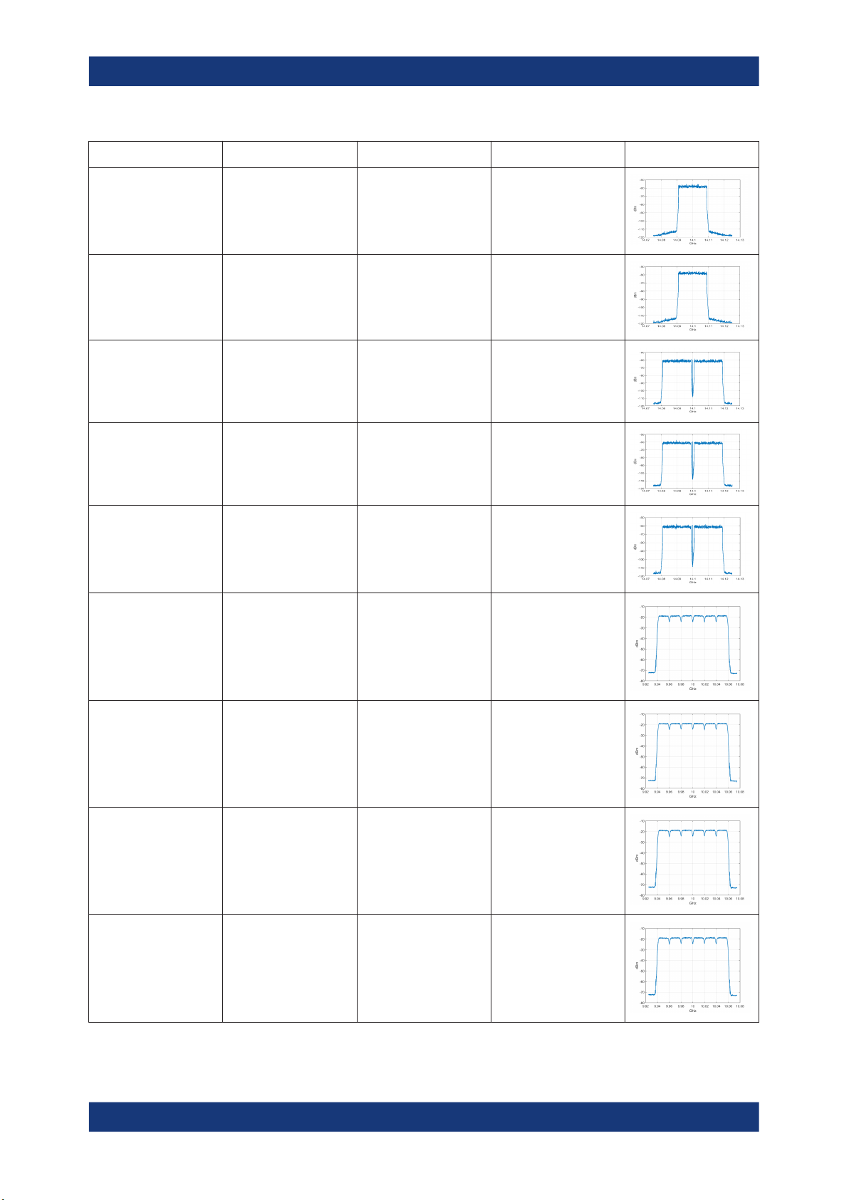
2.2 Provided reference signals
For an overview of the supported reference signals depending on the installed options,
see Table 2-1.
11User Manual 1178.5714.02 ─ 08

R&S®SMW-K130/-K355
Table 2-1: Reference signals
About OneWeb option
Provided reference signals
Filename Description R&S SMW-B9 R&S SMW-B10
HY11H9878-2_2.0_FL_8psk_
736399.8358.wv
HY11H9878-2_2.0_FL_16qa
m_736399.8052.wv
HY11H9878-2_2.0_FL_qpsk_
736399.837.wv
HY11H9951-2_2.0_RL_8PSK
_1CC_1cl_736371.1831
.wv
HY11H9951-2_2.0_RL_8PSK
_2CC_1cl_736371.1817
.wv
Length: 1 Frame
Sampling
Rate:921.600MHz
FL_8PSK
Length: 1 Frame
Sampling
Rate:921.600MHz
FL_16QAM
Length: 1 Frame
Sampling
Rate:921.600MHz
FL_QPSK
Length: 1 Frame
Sampling
Rate:30.720MHz
RL_8PSK
Length: 1 Frame
Sampling
Rate:61.44MHz
RL_8PSK
x
x
x
x x
x x
HY11H9951-2_2.0_RL_16QA
M_1CC_1cl_736371.18
33.wv
HY11H9951-2_2.0_RL_16QA
M_2CC_1cl_736371.18
23.wv
HY11H9951-2_2.0_RL_QPS
K_1CC_1cl_736371.182
7.wv
HY11H9951-2_2.0_RL_QPS
K_2CC_1cl_736371.18.
wv
Length: 1 Frame
Sampling
Rate:30.72MHz
RL_16QAM
Length: 1 Frame
Sampling
Rate:61.44MHz
RL_16QAM
Length: 1 Frame
Sampling
Rate:30.72MHz
RL_QPSK
Length: 1 Frame
Sampling
Rate:61.44MHz
RL_QPSK
x x
x x
x x
x x
12User Manual 1178.5714.02 ─ 08

R&S®SMW-K130/-K355
About OneWeb option
Provided reference signals
Filename Description R&S SMW-B9 R&S SMW-B10
HY11HA563-1_1.0_RL_8PSK
_1CC_2cl_736408.2524
.wv
HY11HA563-1_1.0_RL_8PSK
_2CC_2cl_736408.2531
.wv
HY11HA563-1_1.0_RL_16QA
M_1CC_2cl_736408.25
21.wv
HY11HA563-1_1.0_RL_16QA
M_2CC_2cl_736408.25
28.wv
HY11HA563-1_1.0_RL_QPS
K_1CC_2cl_736408.251
8.wv
Length: 1 Frame
Sampling
Rate:30.72MHz
RL_8PSK
Length: 1 Frame
Sampling
Rate:61.44MHz
RL_8PSK
Length: 1 Frame
Sampling
Rate:30.72MHz
RL_16QAM
Length: 1 Frame
Sampling
Rate:61.44MHz
RL_16QAM
Length: 1 Frame
Sampling
Rate:30.72MHz
RL_QPSK
x x
x x
x x
x x
x x
HY11HA563-1_1.0_RL_QPS
K_2CC_2cl_736408.252
7.wv
HY11HA610-1_1.0_FLwvfm7
36292.5983.8psk.notch.
wv
HY11HA610-1_1.0_FLwvfm7
36292.5996.qpsk.notch.
wv
HY11HA610-1_1.0_FLwvfm7
36345.2465.16qam.notc
h.wv
HY11HA674-1_1.0_RL_8PSK
_1CC_TDD_736523.40
25.wv
Length: 1 Frame
Sampling
Rate:61.44MHz
RL_QPSK
Length: 1 Frame
Sampling
Rate:921.600MHz
FL_8PSK
Length: 1 Frame
Sampling
Rate:921.600MHz
QPSK
Length: 1 Frame
Sampling
Rate:921.600MHz
FL_16QAM
Length: 1 Frame
Sampling
Rate:30.72MHz
RL_8PSK
x x
x
x
x
x x
13User Manual 1178.5714.02 ─ 08
R&S®SMW-K130/-K355
About OneWeb option
Provided reference signals
Filename Description R&S SMW-B9 R&S SMW-B10
HY11HA674-1_1.0_RL_16QA
M_1CC_TDD_736523.4
179.wv
HY11HA674-1_1.0_RL_QPS
K_1CC_TDD_736523.4
201.wv
HY11HA674-2_1.0_RL_8PSK
_2CC_TDD_736523.43
83.wv
HY11HA674-2_1.0_RL_16QA
M_2CC_TDD_736523.4
41.wv
HY11HA674-2_1.0_RL_QPS
K_2CC_TDD_736523.4
217.wv
Length: 1 Frame
Sampling
Rate:30.72MHz
RL_16QAM
Length: 1 Frame
Sampling
Rate:30.72MHz
RL_QPSK
Length: 1 Frame
Sampling
Rate:61.44MHz
RL_8PSK
Length: 1 Frame
Sampling
Rate:61.44MHz
RL_16QAM
Length: 1 Frame
Sampling
Rate:61.44MHz
RL_QPSK
x x
x x
x x
x x
x x
OneWeb_RL_6Carrier_8PSK_channel1.wv
OneWeb_RL_6Carrier_8PSK_channel2.wv
OneWeb_RL_6Carrier_8PSK_channel3.wv
OneWeb_RL_6Carrier_8PSK_channel4.wv
Length: 1 Frame
Sampling
Rate:258.774200 MHz
RL_6Carrier_8PSK
Length: 1 Frame
Sampling
Rate:258.774200 MHz
RL_6Carrier_8PSK
Length: 1 Frame
Sampling
Rate:258.774200 MHz
RL_6Carrier_8PSK
Length: 1 Frame
Sampling
Rate:258.774200 MHz
RL_6Carrier_8PSK
x
x
x
x
14User Manual 1178.5714.02 ─ 08

R&S®SMW-K130/-K355
About OneWeb option
Provided reference signals
Filename Description R&S SMW-B9 R&S SMW-B10
OneWeb_RL_6Carrier_8PSK_channel5.wv
OneWeb_RL_6Carrier_8PSK_channel6.wv
OneWeb_RL_6Carrier_8PSK_channel7.wv
OneWeb_RL_6Carrier_8PSK_channel8.wv
Length: 1 Frame
Sampling
Rate:258.774200 MHz
RL_6Carrier_8PSK
Length: 1 Frame
Sampling
Rate:258.774200 MHz
RL_6Carrier_8PSK
Length: 1 Frame
Sampling
Rate:258.774200 MHz
RL_6Carrier_8PSK
Length: 1 Frame
Sampling
Rate:258.774200 MHz
RL_6Carrier_8PSK
x
x
x
x
OneWeb_RL_6Carrier_QPSK_channel1.wv
OneWeb_RL_6Carrier_QPSK_channel2.wv
OneWeb_RL_6Carrier_QPSK_channel3.wv
OneWeb_RL_6Carrier_QPSK_channel4.wv
Length: 1 Frame
Sampling
Rate:258.774200 MHz
RL_6Carrier_QPSK
Length: 1 Frame
Sampling
Rate:258.774200 MHz
RL_6Carrier_QPSK
Length: 1 Frame
Sampling
Rate:258.774200 MHz
RL_6Carrier_QPSK
Length: 1 Frame
Sampling
Rate:258.774200 MHz
RL_6Carrier_QPSK
x
x
x
x
15User Manual 1178.5714.02 ─ 08

R&S®SMW-K130/-K355
About OneWeb option
Provided reference signals
Filename Description R&S SMW-B9 R&S SMW-B10
OneWeb_RL_6Carrier_QPSK_channel5.wv
OneWeb_RL_6Carrier_QPSK_channel6.wv
OneWeb_RL_6Carrier_QPSK_channel7.wv
OneWeb_RL_6Carrier_QPSK_channel8.wv
Length: 1 Frame
Sampling
Rate:258.774200 MHz
RL_6Carrier_QPSK
Length: 1 Frame
Sampling
Rate:258.774200 MHz
RL_6Carrier_QPSK
Length: 1 Frame
Sampling
Rate:258.774200 MHz
RL_6Carrier_QPSK
Length: 1 Frame
Sampling
Rate:258.774200 MHz
RL_6Carrier_QPSK
x
x
x
x
OneWeb_RL_48Carrier_8PSK.wv
OneWeb_RL_48Carrier_QPSK_v4.wv
Length: 1 Frame
Sampling Rate:2.4GHz
RL_48Carrier_QPSK
Length: 1 Frame
Sampling Rate:2.4GHz
RL_48Carrier_8PSK
x
x
16User Manual 1178.5714.02 ─ 08

R&S®SMW-K130/-K355
3 Oneweb configuration and settings
Access:
► Select "Baseband > OneWeb".
The remote commands required to define these settings are described in Chapter 5,
"Remote-control commands", on page 135.
Settings:
● General settings......................................................................................................17
● Predefined mode settings....................................................................................... 19
● User-defined mode settings.................................................................................... 20
● General downlink settings.......................................................................................21
● Downlink frame configuration..................................................................................29
● General uplink settings............................................................................................57
● Uplink frame configuration...................................................................................... 73
● User equipment configuration................................................................................. 94
● Trigger settings......................................................................................................113
● Marker settings......................................................................................................119
● Clock settings........................................................................................................120
● Filter/clipping/ARB settings................................................................................... 122
● Local and global connectors settings....................................................................131
Oneweb configuration and settings
General settings
3.1 General settings
Access:
► Select "Baseband > Beyond 3G Standards > OneWeb".
17User Manual 1178.5714.02 ─ 08

R&S®SMW-K130/-K355
This dialog comprises the standard general settings.
Settings:
State..............................................................................................................................18
Set to Default................................................................................................................ 18
Save/Recall...................................................................................................................18
Generate Waveform File...............................................................................................18
Mode............................................................................................................................. 18
State
Activates the standard and deactivates all the other digital standards and digital modulation modes in the same path.
Remote command:
[:SOURce<hw>]:BB:ONEWeb:STATe on page 137
Set to Default
Calls the default settings. The values of the main parameters are listed in the following
table.
Remote command:
[:SOURce<hw>]:BB:ONEWeb:PRESet on page 137
Oneweb configuration and settings
General settings
Save/Recall
Accesses the "Save/Recall" dialog, that is the standard instrument function for storing
and recalling the complete dialog-related settings in a file. The provided navigation
possibilities in the dialog are self-explanatory.
The filename and the directory, in which the settings are stored, are user-definable; the
file extension is predefined.
See also, chapter "File and Data Management" in the R&S SMW user manual.
Remote command:
[:SOURce<hw>]:BB:ONEWeb:SETTing:CATalog? on page 138
[:SOURce<hw>]:BB:ONEWeb:SETTing:LOAD on page 138
[:SOURce<hw>]:BB:ONEWeb:SETTing:STORe on page 138
Generate Waveform File
With enabled signal generation, triggers the instrument to save the current settings of
an arbitrary waveform signal in a waveform file with predefined extension *.wv. You
can define the filename and the directory, in that you want to save the file.
Using the ARB modulation source, you can play back waveform files and/or process
the file to generate multi-carrier or multi-segment signals.
Remote command:
[:SOURce<hw>]:BB:ONEWeb:WAVeform:CREate on page 138
Mode
Indicates that predefined configurations can be loaded.
18User Manual 1178.5714.02 ─ 08

R&S®SMW-K130/-K355
Oneweb configuration and settings
Predefined mode settings
"Predefined"
"User-Defined"
Remote command:
[:SOURce<hw>]:BB:ONEWeb:CMOD on page 139
Option: R&S SMW-K355
You can load predefined configuration files, see Predefined mode set-
tings.
Option: R&S SMW-K130
Allows the configuration of the frame structure for different link directions in OneWeb system, see Chapter 3.3, "User-defined mode set-
tings", on page 20.
For uplink configuration, see Chapter 3.7, "Uplink frame configura-
tion", on page 73, Chapter 3.7, "Uplink frame configuration",
on page 73 and Chapter 3.8, "User equipment configuration",
on page 94.
For downlink configuration, see Chapter 3.4, "General downlink set-
tings", on page 21 and Chapter 3.5, "Downlink frame configuration",
on page 29.
3.2 Predefined mode settings
Access:
1. Select "Baseband" > "Beyond 3G Standards" > "OneWeb".
2. Select "Mode" > "Predefined".
In this mode, you can load the predefined reference signals.
Settings:
Reference Signal...........................................................................................................20
19User Manual 1178.5714.02 ─ 08

R&S®SMW-K130/-K355
Reference Signal
Selects and loads a predefined reference signal.
For details, see Chapter 2, "About OneWeb option", on page 11.
Remote command:
[:SOURce<hw>]:BB:ONEWeb:REFSignal on page 139
3.3 User-defined mode settings
Access:
1. Select "Baseband" > "Beyond 3G Standards" > "OneWeb".
2. Select "Mode" > "User-defined".
Oneweb configuration and settings
User-defined mode settings
In this mode, you can defined the uplink and downlink signals for OneWeb.
Note: For uplink signal, only "ARB configuration..." is supported.
For downlink signal, the "Filter/Clipping/ARB..." is supported.
Settings:
Duplexing...................................................................................................................... 20
Link Direction................................................................................................................ 21
General DL Settings/General UL Settings.................................................................... 21
Frame Configuration..................................................................................................... 21
Filter/Clipping/ARB Settings..........................................................................................21
Duplexing
Displays the duplexing mode. The duplexing mode determines how the uplink and
downlink signals are separated.
Only FDD is supported in both uplink and downlink directions.
20User Manual 1178.5714.02 ─ 08

R&S®SMW-K130/-K355
Remote command:
[:SOURce<hw>]:BB:ONEWeb:DUPLexing? on page 137
Link Direction
Selects the transmission direction.
"Downlink / Forward (SC-TDM)"
"Uplink / Reverse (SC-FDMA)"
Remote command:
[:SOURce<hw>]:BB:ONEWeb:LINK on page 137
General DL Settings/General UL Settings
Accesses the "General DL Settings / General UL Settings" dialog for configuring the
OneWeb system.
For description of the available settings, refer to Chapter 3.4, "General downlink set-
tings", on page 21 and Chapter 3.6, "General uplink settings", on page 57 respec-
tively.
Remote command:
n.a.
Oneweb configuration and settings
General downlink settings
The transmission direction selected is ground station to user terminal.
The signal corresponds to that of a ground station.
The transmission direction selected is user terminal to ground station.
The signal corresponds to that of a user terminal.
Frame Configuration
Accesses the "Frame Configuration" dialog for configuring the allocation of the
resource blocks to the different users, as well as the configuration of the users.
The available settings depend on the selected link direction. For description, refer to
Chapter 3.5, "Downlink frame configuration", on page 29 and Chapter 3.7, "Uplink
frame configuration", on page 73 respectively.
Remote command:
n.a.
Filter/Clipping/ARB Settings
Accesses the dialog for setting baseband filtering, clipping, and the sequence length of
the arbitrary waveform component, see Chapter 3.12, "Filter/clipping/ARB settings",
on page 122.
Remote command:
n.a.
3.4 General downlink settings
Option: R&S SMW-K130
Access:
1. Select "General > Link Direction > Downlink / Forward (SC-TDM)".
21User Manual 1178.5714.02 ─ 08

R&S®SMW-K130/-K355
2. Select "General Settings "
This dialog allows configuring the OneWeb system for transmission direction downlink.
Settings:
● PDSCH scheduling settings....................................................................................22
● Physical settings..................................................................................................... 23
● Cell-specific settings............................................................................................... 25
● Downlink signals settings........................................................................................26
● Antenna ports settings............................................................................................ 27
3.4.1 PDSCH scheduling settings
Access:
1. Select "General > Link Direction > Downlink /Forward (SC-TDM)".
Oneweb configuration and settings
General downlink settings
2. Select "General DL Settings > Scheduling".
The "PDSCH scheduling" is fixed to Auto/DCI mode.
Remote command:
[:SOURce<hw>]:BB:ONEWeb:DL:CONF:MODE? on page 154
Overview of the scheduling methods
In the R&S SMW, there are different approaches to configure and schedule the different PDSCH allocations:
●
According to the configuration made for the DCIs ("Auto/DCI")
22User Manual 1178.5714.02 ─ 08

R&S®SMW-K130/-K355
This mode assures a OneWeb signal and the PDSCH allocations are configured
automatically according to the configuration of the PDCCH DCIs.
There are however limitations in the configuration flexibility, especially regarding
the power setting, see "Limitations and interdependencies in the Auto/DCI and
Auto Sequence modes" on page 23.
Limitations and interdependencies in the Auto/DCI and Auto Sequence modes
The generation of a compliant signal requires some limitations in the configuration flexibility, especially regarding the power setting:
●
The value of the parameter Reference Signal Power is fixed to 0dB.
●
The PDSCH Power of each allocation belonging to a user is set as configured with
the parameter Power for the corresponding user in the "Configure User" dialog.
●
All four users are activated with enabled Scrambling and Channel Coding.
●
Not all combinations of DCI Table, Users and UE_ID/n_RNTI are allowed, see
Table 3-1.
Table 3-1: DCI Formats dependencies
User UE ID/n_RNTI DCI Format
Oneweb configuration and settings
General downlink settings
User x As defined for the corresponding user 0, 1OW, 1A, 2OW, 3, 3A, 3OW
P-RNTI 65534 1A
SI-RNTI 65535
RA-RNTI As defined with the parameter "General DL Setting"
> RA_RNTI
3.4.2 Physical settings
Access:
1. Select "General > Link Direction > Downlink / Forward (SC-TDM)".
1A
1A
23User Manual 1178.5714.02 ─ 08

R&S®SMW-K130/-K355
2. Select "General DL Settings > Physical".
Oneweb configuration and settings
General downlink settings
In this dialog, the channel bandwidth respectively the number of resource blocks
per subframe is selected. The other parameters are fixed and read-only.
Settings:
Channel Bandwidth.......................................................................................................24
Number of Resource Blocks Per Subframe.................................................................. 24
Occupied Bandwidth..................................................................................................... 24
Sampling Rate...............................................................................................................25
Channel Bandwidth
Displays the channel bandwidth.
The "Sampling Rate" and "Occupied Bandwidth" are therefore determined by the
parameter "Number of Resource Blocks Per Subframe".
Remote command:
[:SOURce<hw>]:BB:ONEWeb:DL:BW? on page 154
Number of Resource Blocks Per Subframe
Displays the number of used resource blocks for the selected "Channel Bandwidth".
The number of resource blocks are fixed to 1152.
The sampling rate and the occupied bandwidth are determined by the parameter
"Number of Resource Blocks Per Subframe".
Remote command:
[:SOURce<hw>]:BB:ONEWeb:DL:NORB? on page 155
Occupied Bandwidth
Displays the occupied bandwidth, calculated from the parameter "Number of Resource
Blocks Per Subframe".
24User Manual 1178.5714.02 ─ 08

R&S®SMW-K130/-K355
Remote command:
[:SOURce<hw>]:BB:ONEWeb:DL:OCCBandwidth? on page 155
Sampling Rate
Displays the sampling rate, calculated from the parameter "Number of Resource
Blocks Per Subframe".
Remote command:
[:SOURce<hw>]:BB:ONEWeb:DL:SRATe? on page 156
3.4.3 Cell-specific settings
Access:
1. Select "General > Link Direction > Downlink / Forward (SC-TDM)".
2. Select "General DL Settings > Cell".
Oneweb configuration and settings
General downlink settings
The "Cell-Specific Settings" section comprises the physical layer cell identity settings and the random-access response identity for user.
Settings:
Cell ID........................................................................................................................... 25
RA_RNTI.......................................................................................................................26
Cell ID
Sets the cell identity.
There are 256 unique physical layer cell identities (Cell ID).
The Cell ID determinates:
●
The downlink reference signal pseudo-random sequence
●
The pseudo-random sequence used for scrambling
25User Manual 1178.5714.02 ─ 08

R&S®SMW-K130/-K355
Remote command:
[:SOURce<hw>]:BB:ONEWeb:DL[:PLCI]:CID on page 156
RA_RNTI
Sets the random-access response identity RA-RNTI for the users.
The value selected here determined the value of the parameter UE_ID/n_RNTI in case
a RA_RNTI "User" is selected.
Remote command:
[:SOURce<hw>]:BB:ONEWeb:DL:CSETtings:RARNti on page 156
3.4.4 Downlink signals settings
Access:
1. Select "General > Link Direction > Downlink / Forward (SC-TDM)".
2. Select "General DL Settings > Signals".
Oneweb configuration and settings
General downlink settings
The "Signals" dialog comprises the settings of all DL signals.
Settings:
Downlink Reference Signal Structure........................................................................... 26
└ Reference Signal Power................................................................................. 27
Synchronization Signal Settings....................................................................................27
└ P-SYNC State.................................................................................................27
└ P-SYNC Power............................................................................................... 27
Downlink Reference Signal Structure
Comprises the downlink reference signal settings, like the power of the reference signals.
26User Manual 1178.5714.02 ─ 08

R&S®SMW-K130/-K355
Reference Signal Power ← Downlink Reference Signal Structure
Displays the power of the reference signal.
Remote command:
[:SOURce<hw>]:BB:ONEWeb:DL:REFSig:POWer? on page 156
Synchronization Signal Settings
In the "Synchronization Signal Settings" section, the power of the P-SYNC is set.
P-SYNC State ← Synchronization Signal Settings
Enables/disables the generation of the P-SYNC signal.
Remote command:
[:SOURce<hw>]:BB:ONEWeb:DL:SYNC:PSTate on page 157
P-SYNC Power ← Synchronization Signal Settings
Sets the power of the P-SYNC allocations.
Remote command:
[:SOURce<hw>]:BB:ONEWeb:DL:SYNC:PPOWer on page 157
Oneweb configuration and settings
General downlink settings
3.4.5 Antenna ports settings
Access:
1. Select "General > Link Direction > Downlink / Forward (SC-TDM)".
2. Select "General DL Settings > Antenna Ports".
In the "Antenna Ports" section, TxAntenna is fixed at 1 for both MIMO configuration
and simulated antenna.
The provided settings depend on the selected "System Configuration > Fading and
Baseband Configuration > Mode" and the enabled LxMxN MIMO scenario, i.e. the
number of enabled "Entities", "Basebands" and "Streams". Refer to the user manual of the base unit.
See Table 3-2 and compare the displayed settings for the same 4x4 MIMO configu-
ration.
27User Manual 1178.5714.02 ─ 08

R&S®SMW-K130/-K355
Oneweb configuration and settings
General downlink settings
Table 3-2: Antenna ports settings depending on the enabled MxN MIMO configuration and "System Configuration" mode
"System Configuration >
Fading/Baseband Configuration > BB Source Config"
"Separated"
"Coupled"
"System Configuration > Fading/Baseband Configuration > 1x4x4"
Settings:
Global MIMO Configuration...........................................................................................28
Simulated Antenna........................................................................................................29
Cell-Specific Antenna Port Mapping............................................................................. 29
└ Mapping Coordinates......................................................................................29
└ Mapping table................................................................................................. 29
Global MIMO Configuration
Displays the number of transmit antennas of the simulated OneWeb system.
The "Global MIMO Configuration" is fixed to one TxAntenna.
The Downlink Reference Signal Structure is set accordingly.
Note: One baseband simulates one antenna.
"1 TxAntenna"
Enables single antenna port transmission.
28User Manual 1178.5714.02 ─ 08

R&S®SMW-K130/-K355
Remote command:
[:SOURce<hw>]:BB:ONEWeb:DL:MIMO:CONFiguration? on page 157
Simulated Antenna
In "System Configuration > Fading/Baseband Configuration > Mode > Standard",
determines the antenna to be simulated in the current baseband.
The "Simulated Antenna" is fixed to one antenna.
The Downlink Reference Signal Structure is set accordingly.
Remote command:
[:SOURce<hw>]:BB:ONEWeb:DL:MIMO:ANTenna? on page 158
Cell-Specific Antenna Port Mapping
Comprises the settings for defining the mapping of the logical antenna ports to the
available physical Tx antennas (Basebands).
Mapping Coordinates ← Cell-Specific Antenna Port Mapping
Switches representation between the "Cartesian (Real/Imag)" and "Cylindrical (Magn./
Phase)" coordinates.
Remote command:
[:SOURce<hw>]:BB:ONEWeb:DL:MIMO:APM:MAPCoordinates on page 158
Oneweb configuration and settings
Downlink frame configuration
Mapping table ← Cell-Specific Antenna Port Mapping
The mapping table is a matrix with number of rows equal to the number of physical Tx
antennas and number of columns equal of the number of antenna ports (AP).
The default mapping is selected to fit the current configuration.
Remote command:
[:SOURce<hw>]:BB:ONEWeb:DL:MIMO:APM:CS:CELL:BB<st0> on page 158
[:SOURce<hw>]:BB:ONEWeb:DL:MIMO:APM:CS:AP<dir0>:ROW<st0>:REAL
on page 158
[:SOURce<hw>]:BB:ONEWeb:DL:MIMO:APM:CS:AP<dir0>:ROW<st0>:
IMAGinary on page 159
3.5 Downlink frame configuration
Option: R&S SMW-K130
Access:
1. Select "General > Link Direction > Downlink / Forward (SC-TDM)".
2. Select "Frame Configuration".
The "DL Frame Configuration" dialog allows you to configure the subframes and
the OFDMA resource allocations. The dialog consists of several tabs.
29User Manual 1178.5714.02 ─ 08

R&S®SMW-K130/-K355
Settings:
● General frame configuration settings...................................................................... 30
● User configuration settings......................................................................................31
● Subframe configuration settings..............................................................................34
● DL resource allocation table....................................................................................35
● PCFICH settings..................................................................................................... 38
● PDCCH settings......................................................................................................40
● DCI format configuration......................................................................................... 47
● Enhanced PBCH and PDSCH settings...................................................................52
3.5.1 General frame configuration settings
Access:
1. Select "General > Link Direction > Downlink / Forward (SC-TDM)".
2. Select "Frame Configuration > General".
Oneweb configuration and settings
Downlink frame configuration
This dialog comprises the general settings that can be configured in the downlink
subframe.
Settings:
No Of Configurable (DL) Subframes.............................................................................30
Reset All Subframes..................................................................................................... 31
No Of Configurable (DL) Subframes
Sets the number of configurable subframes. Only the downlink and the special subframes are enabled for configuration.
30User Manual 1178.5714.02 ─ 08
 Loading...