


R&S®SMW-K149
HRP UWB 802.15.4
User Manual
(;ÝDÛ2)
1179207702
Version 04

This document describes the following software options:
●
R&S®SMW-K149 HRP UWB (1414.6912.xx)
This manual describes firmware version FW 5.00.166.xx and later of the R&S®SMW200A.
© 2022 Rohde & Schwarz GmbH & Co. KG
Muehldorfstr. 15, 81671 Muenchen, Germany
Phone: +49 89 41 29 - 0
Email: info@rohde-schwarz.com
Internet: www.rohde-schwarz.com
Subject to change – data without tolerance limits is not binding.
R&S® is a registered trademark of Rohde & Schwarz GmbH & Co. KG.
Trade names are trademarks of the owners.
1179.2077.02 | Version 04 | R&S®SMW-K149
The following abbreviations are used throughout this manual: R&S®SMW200A is abbreviated as R&S SMW, R&S®WinIQSIM2 is
abbreviated as R&S WinIQSIM2; the license types 02/03/07/11/13/16/12 are abbreviated as xx.

R&S®SMW-K149
1 Welcome to the HRP UWB option........................................................ 5
1.1 Key features...................................................................................................................5
1.2 Accessing the HRP UWB dialog.................................................................................. 5
1.3 What's new.....................................................................................................................6
1.4 Documentation overview..............................................................................................6
1.4.1 Getting started manual....................................................................................................6
1.4.2 User manuals and help................................................................................................... 6
1.4.3 Tutorials...........................................................................................................................7
1.4.4 Service manual............................................................................................................... 7
1.4.5 Instrument security procedures.......................................................................................7
1.4.6 Printed safety instructions............................................................................................... 7
Contents
Contents
1.4.7 Data sheets and brochures............................................................................................. 7
1.4.8 Release notes and open source acknowledgment (OSA).............................................. 7
1.4.9 Application notes, application cards, white papers, etc...................................................8
1.5 Scope............................................................................................................................. 8
1.6 Notes on screenshots...................................................................................................8
2 About the HRP UWB option.................................................................. 9
2.1 Required options...........................................................................................................9
2.2 HRP UWB signal properties......................................................................................... 9
2.2.1 Frame structure...............................................................................................................9
2.2.1.1 Preamble.......................................................................................................................10
2.2.1.2 Data...............................................................................................................................11
2.3 Operating frequency bands....................................................................................... 12
3 HRP UWB configuration and settings................................................13
3.1 General settings.......................................................................................................... 13
3.2 Frame configuration settings.....................................................................................16
3.2.1 General settings............................................................................................................ 17
3.2.2 SYNC settings...............................................................................................................18
3.2.3 Data settings................................................................................................................. 20
3.2.4 MAC header configuration settings............................................................................... 24
3.2.5 STS settings..................................................................................................................28
3User Manual 1179.2077.02 ─ 04

R&S®SMW-K149
3.3 Impairments settings.................................................................................................. 30
4 Signal generation control....................................................................32
4.1 Filter/Clipping/ARB settings...................................................................................... 32
4.1.1 Filter settings.................................................................................................................32
4.1.2 Clipping settings............................................................................................................37
4.1.3 ARB settings................................................................................................................. 38
4.2 Trigger settings........................................................................................................... 38
4.3 Marker settings............................................................................................................43
4.4 Clock settings..............................................................................................................45
4.5 Local and global connectors settings.......................................................................46
5 Remote control commands.................................................................47
5.1 General commands.....................................................................................................48
Contents
5.2 Frame configuration commands............................................................................... 53
5.3 MAC header commands............................................................................................. 66
5.4 Impairments commands.............................................................................................76
5.5 Filter commands......................................................................................................... 76
5.6 Clipping commands....................................................................................................81
5.7 Trigger commands......................................................................................................82
5.8 Marker commands...................................................................................................... 89
5.9 Clock commands........................................................................................................ 90
List of commands................................................................................ 92
Index......................................................................................................95
4User Manual 1179.2077.02 ─ 04

R&S®SMW-K149
1 Welcome to the HRP UWB option
Welcome to the HRP UWB option
Accessing the HRP UWB dialog
The R&S SMW-K149 is a firmware application that adds functionality to generate signals in accordance with the HRP UWB standard. The standard is specified in
802.15.4.z specification.
This user manual contains a description of the functionality that the application provides, including remote control operation.
All functions not discussed in this manual are the same as in the base unit and are
described in the R&S SMW user manual. The latest version is available at:
www.rohde-schwarz.com/manual/SMW200A
Installation
You can find detailed installation instructions in the delivery of the option or in the
R&S SMW service manual.
● Key features..............................................................................................................5
● Accessing the HRP UWB dialog............................................................................... 5
● What's new................................................................................................................6
● Documentation overview...........................................................................................6
● Scope........................................................................................................................8
● Notes on screenshots............................................................................................... 8
1.1 Key features
The option R&S SMW-K149 HRP UWB features:
●
HRP UWB 802.15.4 signal generation compliant with HRP non-ERDEV mode
●
HRP UWB 802.15.4z signal generation compliant with HRP-ERDEV base pulse
repetition frequency (BPRF) mode
●
HRP UWB 802.15.4z signal generation compliant with HRP-ERDEV higher pulse
repetition frequency (HPRF) mode
1.2 Accessing the HRP UWB dialog
To open the dialog with HRP UWB settings
► In the block diagram of the R&S SMW, select "Baseband > HRP UWB".
A dialog box opens, that displays the provided general settings.
The signal generation is not started immediately. To start signal generation with the
default settings, select "State > On".
5User Manual 1179.2077.02 ─ 04

R&S®SMW-K149
1.3 What's new
1.4 Documentation overview
Welcome to the HRP UWB option
Documentation overview
This manual describes firmware version FW 5.00.166.xx and later of the
R&S®SMW200A.
Compared to the previous version, it provides the new features listed below:
●
Additional predefined SFD sequences with sequence lengths of 4 to 64 symbols,
see "SFD" on page 19.
●
Set the frame length to a fixed value of 2 ms, see "Fixed 2 ms Frame Length"
on page 16.
This section provides an overview of the R&S SMW user documentation. Unless specified otherwise, you find the documents on the R&S SMW product page at:
www.rohde-schwarz.com/manual/smw200a
1.4.1 Getting started manual
Introduces the R&S SMW and describes how to set up and start working with the product. Includes basic operations, typical measurement examples, and general information, e.g. safety instructions, etc. A printed version is delivered with the instrument.
1.4.2 User manuals and help
Separate manuals for the base unit and the software options are provided for download:
●
Base unit manual
Contains the description of all instrument modes and functions. It also provides an
introduction to remote control, a complete description of the remote control commands with programming examples, and information on maintenance, instrument
interfaces and error messages. Includes the contents of the getting started manual.
●
Software option manual
Contains the description of the specific functions of an option. Basic information on
operating the R&S SMW is not included.
The contents of the user manuals are available as help in the R&S SMW. The help
offers quick, context-sensitive access to the complete information for the base unit and
the software options.
All user manuals are also available for download or for immediate display on the Internet.
6User Manual 1179.2077.02 ─ 04

R&S®SMW-K149
1.4.3 Tutorials
1.4.4 Service manual
1.4.5 Instrument security procedures
Welcome to the HRP UWB option
Documentation overview
The R&S SMW provides interactive examples and demonstrations on operating the
instrument in form of tutorials. A set of tutorials is available directly on the instrument.
Describes the performance test for checking compliance with rated specifications, firmware update, troubleshooting, adjustments, installing options and maintenance.
The service manual is available for registered users on the global Rohde & Schwarz
information system (GLORIS):
https://gloris.rohde-schwarz.com
Deals with security issues when working with the R&S SMW in secure areas. It is available for download on the Internet.
1.4.6 Printed safety instructions
Provides safety information in many languages. The printed document is delivered with
the product.
1.4.7 Data sheets and brochures
The data sheet contains the technical specifications of the R&S SMW. It also lists the
options and their order numbers and optional accessories.
The brochure provides an overview of the instrument and deals with the specific characteristics.
See www.rohde-schwarz.com/brochure-datasheet/smw200a
1.4.8 Release notes and open source acknowledgment (OSA)
The release notes list new features, improvements and known issues of the current
firmware version, and describe the firmware installation.
The open-source acknowledgment document provides verbatim license texts of the
used open source software.
See www.rohde-schwarz.com/firmware/smw200a
7User Manual 1179.2077.02 ─ 04

R&S®SMW-K149
1.4.9 Application notes, application cards, white papers, etc.
1.5 Scope
Welcome to the HRP UWB option
Notes on screenshots
These documents deal with special applications or background information on particular topics.
See www.rohde-schwarz.com/application/smw200a and www.rohde-schwarz.com/
manual/smw200a
Tasks (in manual or remote operation) that are also performed in the base unit in the
same way are not described here.
In particular, it includes:
●
Managing settings and data lists, like saving and loading settings, creating and
accessing data lists, or accessing files in a particular directory.
●
Information on regular trigger, marker and clock signals and filter settings, if appropriate.
●
General instrument configuration, such as checking the system configuration, configuring networks and remote operation
●
Using the common status registers
For a description of such tasks, see the R&S SMW user manual.
1.6 Notes on screenshots
When describing the functions of the product, we use sample screenshots. These
screenshots are meant to illustrate as many as possible of the provided functions and
possible interdependencies between parameters. The shown values may not represent
realistic usage scenarios.
The screenshots usually show a fully equipped product, that is: with all options installed. Thus, some functions shown in the screenshots may not be available in your particular product configuration.
8User Manual 1179.2077.02 ─ 04

R&S®SMW-K149
2 About the HRP UWB option
2.1 Required options
About the HRP UWB option
HRP UWB signal properties
The equipment layout for generating HRP UWB signals includes:
●
Wideband baseband generator (R&S SMW-B9)
●
Wideband baseband main module (R&S SMW-B13XT)
●
Option HRP UWB (R&S SMW-K149) per signal path
●
Optional, option baseband extension to 1 GHz RF bandwidth extension
(R&S SMW-K525) per signal path
●
Optional, option baseband extension to 2 GHz RF bandwidth extension
(R&S SMW-K527) per signal path
You can generate signals via play-back of waveform files at the signal generator. To
create the waveform file using R&S WinIQSIM2, you do not need a specific option.
To play back the waveform file at the signal generator, you have two options:
●
Install the R&S WinIQSIM2 option of the digital standard, e.g. R&S SMW-K255 for
playing LTE waveforms
●
If supported, install the real-time option of the digital standard, e.g. R&S SMW-K55
for playing LTE waveforms
For more information, see data sheet.
2.2 HRP UWB signal properties
HRP UWB PHY signals employ short, band-limited pulses sent at high rate pulse repetition frequencies (HRP).
2.2.1 Frame structure
An HRP UWB PHY frame consists of a preamble part that contains the synchronization
header (SHR) and a data part that contains a PHY header (PHR) and a PHY payload.
The SHR in the preamble comprises the synchronization (SYNC) field and a start-offrame delimiter (SFD) field.
9User Manual 1179.2077.02 ─ 04

R&S®SMW-K149
About the HRP UWB option
HRP UWB signal properties
PHY protocol data unit (PPDU)
SHR PHR PHY payload
SYNC SFD
Preamble
Figure 2-1: HRP UWB PHY frame structure
Data
HRP-ERDEV
P802.15.4z/D07 introduced optional modes and a ciphered scramble time stamp (STS)
sequence into the PHY to improve timestamp robustness and security and to increase
the accuracy of ranging measurements.
A device incorporating these modes is referred to as a higher rate pulse repetition frequency UWB PHY based enhanced ranging capable device (HRP-ERDEV) and
defined in P802.15.4z/D07, chapter 16.1, "General". Operation at the nominal 64 MHz
pulse repetition frequency (PRF) is referred to as the base pulse repetition frequency
(BPRF) mode. Operation at a higher PRF than the BPRF mode, is referred to as the
higher pulse repetition frequency (HPRF) mode.
The frame structure of HRP-ERDEV is shown in the following figure, with the STS in
different positions. The arrow shows the RMARKER reference position for each configuration, which is the peak pulse location associated with the first chip following the
SFD.
STS packet configuration zero
SYNC SFD PHR PHY payload
STS packet configuration one
STS packet configuration two
STS packet configuration three
Figure 2-2: HRP-ERDEV frame structures with RMARKER position
2.2.1.1 Preamble
The SYNC and SFD fields in the preamble consist of repetitions of a preamble symbol
Si. A preamble symbol is constructed from a ternary code sequence Ci = {–1,0,1} by
inserting several chip durations between code symbols. The supported code sequence
lengths are 31 and 127 as defined in IEEE Std 802.15.4-2015 chapter 16.2.4, "Preamble timing parameters". In addition, code sequence length 91 is supported as defined in
P802.15.4z/D07, chapter 16.2.5, "SYNC field". The number of inserted chip durations
is also called delta length and depends on the length of the code sequence and channel number.
SYNC SFD
SYNC
SYNC SFD
SFD
STS PHR PHY payload
PHR PHY payload STS
STS
10User Manual 1179.2077.02 ─ 04

R&S®SMW-K149
About the HRP UWB option
HRP UWB signal properties
The admissible values for the preamble timing parameters that result from the different
code lengths and pulse repetition frequencies are defined in IEEE Std 802.15.4-2015,
chapter 16.2.4, "Preamble timing parameters".
SYNC SFD
Si Si Si Si Si
Ci(0)
Figure 2-3: Construction of preamble symbols from a code sequence
SYNC field
The SYNC field portion of the SHR contains simple repetitions of the preamble symbol.
The number of preamble symbol repetitions are 16, 64, 1024 and 4096 as defined in
IEEE Std 802.15.4-2015, chapter 16.2.4, "Preamble timing parameters". In HPRF
mode, the HRP-ERDEV supports 32 and 64 preamble symbol repetitions as defined in
P802.15.4z/D07, chapter 16.2.5.1, "SYNC Field".
SFD field
The SFD field is spread by the preamble symbols. Each of the preamble symbols is
multiplied by a sequence of {-1, 0, 1}. The supported SFD lengths are 8 (short) and 64
(long) as defined in IEEE Std 802.15.4-2015, chapter 16.2.5.2, "SFD field". In addition,
the SFD sequences corresponding to the BPRF and HPRF modes are supported as
defined in P802.15.4z/D07, chapter 16.2.5.2, "SFD Field".
0 ... 0 Ci(1) 0 ... 0 ... Ci(K-1) 0 ... 0
Delta length
Si... 0 Si 0 -Si Si 0 0 -Si
2.2.1.2 Data
The PHR and PHY payload symbols are modulated using a combination of burst position modulation (BPM) and binary phase-shift keying (BPSK). Each symbol is composed of an active burst of UWB pulses and can carry two bits of information. One bit
is used to determine the position of a burst of pulses, while an additional bit is used to
modulate the phase (polarity) of this same burst. The various data rates are supported
by using variable-length bursts.
PHR field
The PHR field conveys the information necessary to decode the packet to the receiver,
including the following:
●
●
●
The PHR is modulated using BPM-BPSK at either 850 kb/s or 110 kb/s. For the BPRF
mode, the PHR is modulated using BPM-BPSK at 850 kb/s (or optionally at 6.8 Mb/s).
data rate used to transmit the PHY payload
length of PHY payload field
preamble duration
11User Manual 1179.2077.02 ─ 04

R&S®SMW-K149
2.3 Operating frequency bands
About the HRP UWB option
Operating frequency bands
PHY payload field
The PHY payload field is sent at the data rate indicated in the PHR. Due to the variable
code sequence lengths and the different corresponding pulse repetition frequencies
(PRFs) in the preamble, there are several admissible data rates the UWB PHY can
support. The supported data rates are defined in IEEE Std 802.15.4-2015, chapter
16.2.6, "PHR field" and P802.15.4z/D07, chapter 16.2.6.2 "PHR field for HRP-ERDEV
in BPRF mode".
The carrier center frequencies for UWB signals are defined in IEEE Std 802.15.4-2015,
chapter 16.4.1, "Operating frequency bands". The table below provides an overview of
the supported channels by R&S SMW.
Table 2-1: HRP UWB PHY band allocation
Band group Channel Frequency / MHz Bandwidth / MHz Mandatory/optional
0 0 499.2 499.2 Mandatory below 1 GHz
1 (low band) 1 3494.4 499.2 Optional
2 (high band) 5 6489.6 499.2 Optional
2 3993.6 499.2 Optional
3 4492.8 499.2 Mandatory in low band
4 3993.6 1331.2 Optional
6 6988.8 499.2 Optional
7 6489.6 1081.6 Optional
8 7488.0 499.2 Optional
9 7987.2 499.2 Mandatory in high band
10 8486.4 499.2 Optional
11 7987.2 1331.2 Optional
12 8985.6 499.2 Optional
13 9484.8 499.2 Optional
14 9984.0 499.2 Optional
15 9484.8 1354.97 Optional
12User Manual 1179.2077.02 ─ 04

R&S®SMW-K149
3 HRP UWB configuration and settings
3.1 General settings
HRP UWB configuration and settings
General settings
Access:
► Select "Baseband > HRP UWB 802.15.4".
The remote commands required to define these settings are described in Chapter 5,
"Remote control commands", on page 47.
Settings:
● General settings......................................................................................................13
● Frame configuration settings...................................................................................16
● Impairments settings...............................................................................................30
Access:
► Select "Baseband > HRP UWB 802.15.4".
The dialog provides the standard general settings, the default and the "Save/
Recall" settings. Also, it provides access to dialogs with further settings.
Settings:
State..............................................................................................................................14
Set to Default................................................................................................................ 14
Save/Recall...................................................................................................................14
Generate Waveform File...............................................................................................15
Mode............................................................................................................................. 15
Channel Number...........................................................................................................15
Bandwidth..................................................................................................................... 15
Fixed 2 ms Frame Length............................................................................................. 16
Idle Interval....................................................................................................................16
Filter/Clipping/ARB........................................................................................................16
13User Manual 1179.2077.02 ─ 04

R&S®SMW-K149
HRP UWB configuration and settings
General settings
State
Enables the HRP UWB standard.
Enabling this standard disables all the other digital standards and digital modulation
modes in the same baseband.
Remote command:
[:SOURce<hw>]:BB:HUWB:STATe on page 49
Set to Default
Calls the default settings. The values of the main parameters are listed in the following
table.
Parameter Value
"State" Not affected by the "Set to Default"
HRP UWB "Mode" "802.15.4"
"Channel Num" "0"
"Bandwidth" "499.20 MHz"
"Fixed 2 ms Frame Length" Not activated
"Idle Interval" "50.0 µs"
"Filter" "802.15.4z"
Clipping "State" "Off"
ARB "Sequence Length" "1 Frames"
"Trigger" "Auto"
"Marker" "Restart(ARB)"
"Clock" "Internal"
Remote command:
[:SOURce<hw>]:BB:HUWB:PRESet on page 49
Save/Recall
Accesses the "Save/Recall" dialog, that is the standard instrument function for saving
and recalling the complete dialog-related settings in a file. The provided navigation
possibilities in the dialog are self-explanatory.
The settings are saved in a file with predefined extension. You can define the filename
and the directory, in that you want to save the file.
See also, chapter "File and Data Management" in the R&S SMW user manual.
Remote command:
[:SOURce<hw>]:BB:HUWB:SETTing:CATalog on page 50
[:SOURce<hw>]:BB:HUWB:SETTing:DELete on page 50
[:SOURce<hw>]:BB:HUWB:SETTing:LOAD on page 50
[:SOURce<hw>]:BB:HUWB:SETTing:STORe on page 50
14User Manual 1179.2077.02 ─ 04

R&S®SMW-K149
HRP UWB configuration and settings
General settings
Generate Waveform File
With enabled signal generation, triggers the instrument to save the current settings of
an arbitrary waveform signal in a waveform file with predefined extension *.wv. You
can define the filename and the directory, in that you want to save the file.
Using the ARB modulation source, you can play back waveform files and/or process
the file to generate multi-carrier or multi-segment signals.
Remote command:
[:SOURce<hw>]:BB:HUWB:WAVeform:CREate on page 51
Mode
Sets the HRP UWB mode.
"802.15.4"
Enables HRP non-ERDEV mode.
"802.15.4z-BPRF"
Enables HRP-ERDEV base pulse repetition frequency (BPRF) mode.
"802.15.4z-HPRF"
Enables HRP-ERDEV higher pulse repetition frequency (HPRF)
mode.
Remote command:
[:SOURce<hw>]:BB:HUWB:STD on page 52
Channel Number
Sets the channel number, that is a 4-bit value in decimal representation.
The channel number determines the bandwidth and the code index.
Channel number Bandwidth / MHz
0, 1, 8, 12 499.2 1, 2, 9 to 16, 21 to 32
2, 5, 9, 13 499.2 3, 4, 9 to 16, 21 to 32
3, 6, 10, 14 499.2 5, 6, 9 to 16, 21 to 32
4, 11 1331.2 7, 8, 13 to 32
7 1081.6 7, 8, 13 to 32
15 1354.97 7, 8, 13 to 32
1)
Code indexes 25 to 32 require "Mode > 802.15.4z-HPRF".
Code index
1)
Remote command:
[:SOURce<hw>]:BB:HUWB:CNUMber on page 51
Bandwidth
Displays the bandwidth of the HRP UWB signal.
The bandwidth depends on the channel number, see "Channel Number" on page 15.
Remote command:
[:SOURce<hw>]:BB:HUWB:BWIDth? on page 51
15User Manual 1179.2077.02 ─ 04

R&S®SMW-K149
HRP UWB configuration and settings
Frame configuration settings
Fixed 2 ms Frame Length
Sets the frame length of a generated waveform shorter than 2 ms to a fixed value of 2
ms.
If activated, the "Idle Interval" is set to 0.0 µs by default which means the frames are
sent successively without separation.
Generated waveforms longer than 2 ms remain unaffected.
Remote command:
[:SOURce<hw>]:BB:HUWB:F2MS on page 52
Idle Interval
Sets the length of the idle interval.
Remote command:
[:SOURce<hw>]:BB:HUWB:IINTerval on page 52
Filter/Clipping/ARB
Accesses a dialog to set baseband filtering, clipping and the sequence length of the
arbitrary waveform component, see Chapter 4.1, "Filter/Clipping/ARB settings",
on page 32.
3.2 Frame configuration settings
Access:
► Select "Baseband > HRP UWB 802.15.4 > Frame Configuration".
The dialog provides settings to configure HRP UWP frames.
● General settings......................................................................................................17
● SYNC settings.........................................................................................................18
● Data settings........................................................................................................... 20
● MAC header configuration settings.........................................................................24
● STS settings............................................................................................................28
16User Manual 1179.2077.02 ─ 04

R&S®SMW-K149
3.2.1 General settings
HRP UWB configuration and settings
Frame configuration settings
Access:
► Select "Frame Configuration > General".
The tab provides settings to configure the code index and the scrambled timestamp sequence (STS) packets of HRP UWP frames.
Settings:
Code Index....................................................................................................................17
STS Packet Configuration.............................................................................................17
Code Index
Sets the code index, that determines the code sequence.
Available code indexes depend on the channel number and mode, see "Channel Num-
ber" on page 15.
Remote command:
[:SOURce<hw>]:BB:HUWB:FCONfig:CINDex on page 57
STS Packet Configuration
Requires "Mode > 802.15.4z-BPRF" or "Mode > 802.15.4z-HPRF".
Sets the scrambled timestamp sequence (STS) packet configuration. If "STS Packet
Configuration > 1/2/3", you can configure additional STS settings, see Chapter 3.2.5,
"STS settings", on page 28.
Remote command:
[:SOURce<hw>]:BB:HUWB:STS:PC on page 65
17User Manual 1179.2077.02 ─ 04

R&S®SMW-K149
3.2.2 SYNC settings
HRP UWB configuration and settings
Frame configuration settings
Access:
► Select "Frame Configuration > SYNC".
The tab provides settings to configure SYNC settings.
Settings:
Sync Length.................................................................................................................. 18
Delta Length..................................................................................................................18
SFD Length...................................................................................................................19
SFD...............................................................................................................................19
Sync Length
Sets the length of the SYNC field.
Remote command:
[:SOURce<hw>]:BB:HUWB:FCONfig:SYNLength on page 63
Delta Length
Sets the delta length. The length depends on the HRP UWB mode and bandwidth.
HRP UWB mode Bandwidth / MHz Delta length
802.15.4 499.2
1081.6
1331.2
1354.97
802.15.4z-BPRF 499.2
1081.6
1331.2
1354.97
4, 16, 64
4, 16
4, 16
4, 16
4
802.15.4z-HPRF 499.2
1081.6
1331.2
1354.97
4, 16, 64
4, 16
4, 16
4, 16
18User Manual 1179.2077.02 ─ 04

R&S®SMW-K149
HRP UWB configuration and settings
Frame configuration settings
Remote command:
[:SOURce<hw>]:BB:HUWB:FCONfig:DLENgth on page 60
SFD Length
Displays the symbol length of the start-of-frame delimiter (SFD). The length depends
on the HRP UWB mode, see Table 3-1.
Remote command:
[:SOURce<hw>]:BB:HUWB:FCONfig:SFDLength on page 63
SFD
Sets the start-of-frame delimiter (SFD) symbol sequence.
Availability of the SFD sequence and the corresponding SFD length depends on the
HRP UWB mode, see Table 3-1.
Table 3-1: SFD, SFD length and HRP UWB mode
SFD SFD length 802.15.4 802.15.4z-BPRF 802.15.4z-HPRF
0 8 - Supported Supported
1 4 - Supported Supported
2 8 - Supported Supported
3 16 - Supported Supported
4 32 - Supported Supported
User1 8 Supported Supported Supported
User2 16 Supported Supported Supported
User3 32 Supported Supported Supported
Legacy 8 Supported - -
Additional to standard-compliant SFD sequences, you can select three predefined
sequences "User1" to "User3". "802.15.4" mode also supports a legacy sequence.
Remote command:
[:SOURce<hw>]:BB:HUWB:SFD on page 64
19User Manual 1179.2077.02 ─ 04

R&S®SMW-K149
3.2.3 Data settings
HRP UWB configuration and settings
Frame configuration settings
Access:
► Select "Frame Configuration > Data".
The tab provides settings to configure physical data and physical header settings.
For "STS Packet Configuration" = 3, you cannot configure the "Data" settings.
PHY header and PHY payload coding
The data for the physical header and physical payload is segmented into code blocks
for coding via the Reed-Solomon coder. For a data length of 127 bytes (octets), there
are four code blocks segmented from four frames. Table 3-2 gives an overview.
Table 3-2: PHY data length and code block segmentation
Frame Code block b
Number Length [byte] Length [bit] Number b1 [bit] b2 [bit] b3 [bit] b4 [bit]
1 1
to
41
2 42
to
82
3 83
to
123
8
to
328
336
to
656
664
to
984
1 8
to
328
2 330 6
3 330 330 4
0 0 0
to
326
0 0
0
to
324
4 124
to
127
992
to
1016
4 330 330 330 2
to
26
20User Manual 1179.2077.02 ─ 04

R&S®SMW-K149
HRP UWB configuration and settings
Frame configuration settings
Settings:
Physical Data................................................................................................................ 21
└ Data Source....................................................................................................21
└ Viterbi Rate..................................................................................................... 22
└ Convolutional Code Constraint Length........................................................... 22
└ Hop Bursts...................................................................................................... 22
└ Chips Per Burst...............................................................................................22
└ MAC FCS........................................................................................................22
└ MAC FCS Length............................................................................................22
└ MAC Header................................................................................................... 22
└ Mean PRF.......................................................................................................23
└ Data Rate........................................................................................................23
└ PHR Data Rate Mode..................................................................................... 23
PHR (Physical Header).................................................................................................23
└ PHR Bit Rate...................................................................................................23
└ Data Length.................................................................................................... 23
└ Maximum Data Length....................................................................................24
Frame............................................................................................................................24
└ Frame Length..................................................................................................24
Physical Data
Provides settings to configure physical data.
Data Source ← Physical Data
Selects the data source.
Note: The bit order of the output data bits is least significant bit (LSB) first and most
significant bit (MSB) last.
The following standard data sources are available:
●
"All 0, All 1"
An internally generated sequence containing 0 data or 1 data.
●
"PNxx"
An internally generated pseudo-random noise sequence.
●
"Pattern"
An internally generated sequence according to a bit pattern.
Use the "Pattern" box to define the bit pattern.
●
"Data List/Select DList"
A binary data from a data list, internally or externally generated.
Select "Select DList" to access the standard "Select List" dialog.
– Select the "Select Data List > navigate to the list file *.dm_iqd > Select" to
select an existing data list.
– Use the "New" and "Edit" functions to create internally new data list or to edit
an existing one.
– Use the standard "File Manager" function to transfer external data lists to the
instrument.
See also:
●
Section "Modulation Data" in the R&S SMW user manual.
●
Section "File and Data Management" in the R&S SMW user manual.
●
Section "Data List Editor" in the R&S SMW user manual
21User Manual 1179.2077.02 ─ 04

R&S®SMW-K149
HRP UWB configuration and settings
Frame configuration settings
Remote command:
[:SOURce<hw>]:BB:HUWB:FCONfig:DATA on page 58
[:SOURce<hw>]:BB:HUWB:FCONfig:DATA:DSELection on page 59
[:SOURce<hw>]:BB:HUWB:FCONfig:DATA:PATTern on page 59
Viterbi Rate ← Physical Data
Displays the Viterbi rate for convolutional coding.
The rate is fixed to 0.5, except for "Chips Per Burst > 1" it is 1.0.
Remote command:
[:SOURce<hw>]:BB:HUWB:FCONfig:VRATe? on page 63
Convolutional Code Constraint Length ← Physical Data
Requires "Mode > 802.15.4z-HPRF".
Sets the constraint length of the convolutional code.
Remote command:
[:SOURce<hw>]:BB:HUWB:CCCL on page 57
Hop Bursts ← Physical Data
Requires "Mode > 802.15.4" or "Mode > 802.15.4z-BPRF".
Sets the number of hop bursts.
Remote command:
[:SOURce<hw>]:BB:HUWB:FCONfig:HOPBurst on page 61
Chips Per Burst ← Physical Data
Sets the number of chips per burst.
Remote command:
[:SOURce<hw>]:BB:HUWB:FCONfig:CPBurst on page 58
MAC FCS ← Physical Data
Activates the MAC frame check sequence (FCS) field.
Remote command:
[:SOURce<hw>]:BB:HUWB:FCONfig:MCS:STATe on page 61
MAC FCS Length ← Physical Data
Requires "MAC FCS > On".
Sets the length of the MAC frame check sequence (FCS) field.
Remote command:
[:SOURce<hw>]:BB:HUWB:FCONfig:MFL on page 62
MAC Header ← Physical Data
Accesses the "MAC Header Configuration" dialog to configure MAC header parameters.
See Chapter 3.2.4, "MAC header configuration settings", on page 24.
If the MAC header is active, the button displays the length of the MAC header and the
MAC address.
22User Manual 1179.2077.02 ─ 04

R&S®SMW-K149
HRP UWB configuration and settings
Frame configuration settings
Remote command:
[:SOURce<hw>]:BB:HUWB:MACHeader:STRing? on page 75
Mean PRF ← Physical Data
Displays the mean pulse repetition frequency (PRF). The value depends on the hop
bursts.
Remote command:
[:SOURce<hw>]:BB:HUWB:FCONfig:MPRF? on page 62
Data Rate ← Physical Data
Displays the data rate.
Remote command:
[:SOURce<hw>]:BB:HUWB:FCONfig:DR? on page 59
PHR Data Rate Mode ← Physical Data
Requires "Mode > 802.15.4z-BPRF" or "Mode > 802.15.4z-HPRF".
Sets the data rate mode of the physical header.
"DRBM_LP/DRBM_HP"
Requires "Mode > 802.15.4z-BPRF".
"DRHM_LR/DRHM_HR"
Requires "Mode > 802.15.4z-HPRF".
Remote command:
[:SOURce<hw>]:BB:HUWB:PHR:DRM on page 64
PHR (Physical Header)
Provides settings to configure the PHY header and PHY payload.
PHR Bit Rate ← PHR (Physical Header)
Displays the bit rate of the physical header. The value depends on the chips per burst.
Remote command:
[:SOURce<hw>]:BB:HUWB:FCONfig:PHRBrate? on page 62
Data Length ← PHR (Physical Header)
Sets the data length of the PHY header and PHY payload in octets.
PHY header and PHY payload data are segmented into code blocks for Reed-Solomon
encoding, see Table 3-2.
The specified maximum data length is 127 octets. For "Mode > 802.15.4z-HPRF", you
can set a maximum data length of up to 4095 octets.
Mode Maximum data length
"802.15.4z" 127 octets
"802.15.4z-BPRF" 127 octets
"802.15.4z-HPRF" 4095 octets
23User Manual 1179.2077.02 ─ 04

R&S®SMW-K149
HRP UWB configuration and settings
Frame configuration settings
Remote command:
[:SOURce<hw>]:BB:HUWB:FCONfig:DALEngth on page 60
Maximum Data Length ← PHR (Physical Header)
Requires "Mode > 802.15.4z-HPRF".
Sets the maximum data length of the physical header.
Remote command:
[:SOURce<hw>]:BB:HUWB:FCONfig:MDL on page 61
Frame
Provides information on the frame length.
Frame Length ← Frame
Displays the frame length.
The frame length is the sum of the MAC header length, the MAC frame check
sequence (FCS) field length and the data length of the physical header.
Example: Frame lengths with enabled and disabled MAC parameters
By default, the frame length is 20 octets, that is the data length of the physical header.
If you activate the MAC frame check sequence (FCS) field, the frame length increases.
Using the default "MAC FCS Length > 2 Octets", the frame length is 22 octets.
If you further activate the MAC header, the frame length increases. Using the default
"MAC Header > 11 Octets", the frame length is 33 octets.
Remote command:
n.a.
3.2.4 MAC header configuration settings
Access:
► Select "Frame Configuration > Data > MAC Header".
24User Manual 1179.2077.02 ─ 04

R&S®SMW-K149
HRP UWB configuration and settings
Frame configuration settings
The tab provides settings to configure the MAC header bits as defined in IEEE Std
802.15.4-2015.
MAC Header................................................................................................................. 25
Frame Control............................................................................................................... 25
└ Frame Type.....................................................................................................25
└ Security Enabled.............................................................................................26
└ Frame Pending............................................................................................... 26
└ AR...................................................................................................................26
└ PAN ID Compression...................................................................................... 26
└ Reserved.........................................................................................................26
└ Sequence Number Suppression.....................................................................26
└ IE Present....................................................................................................... 26
└ Destination Addressing Mode.........................................................................27
└ Frame Version.................................................................................................27
└ Source Addressing Mode................................................................................27
Sequence Number........................................................................................................ 27
Destination PAN ID........................................................................................................27
Destination Address......................................................................................................28
Source PAN ID.............................................................................................................. 28
Source Address.............................................................................................................28
MAC Header
Activates MAC header information.
Remote command:
[:SOURce<hw>]:BB:HUWB:MACHeader:STATe on page 75
Frame Control
Sets the length and the input value of the frame control field.
You can set lengths of 1 octet or 2 octets. The single bit field below ranges from least
significant bit (LSB) to most significant bit (MSB):
●
1 octet (8-bit): Set bits for fields "Frame Type" to "Reserved".
●
2 octets (16-bit): Set bits for fields "Frame Type" to "Source Addressing Mode".
Remote command:
[:SOURce<hw>]:BB:HUWB:MACHeader:LFRControl on page 71
[:SOURce<hw>]:BB:HUWB:MACHeader:CTRL on page 68
Frame Type ← Frame Control
Sets the bits in the frame type field. The value is a 3-bit value, the field is the LSB part
of the frame control field.
Table 3-3: Frame type settings (IEEE Std 802.15.4-2015, table 7.2.1.1-7)
Decimal value Binary values b2, b1, b0 Description
0 000 Beacon
1 001 Data
2 010 Acknowledgment
3 011 MAC command
25User Manual 1179.2077.02 ─ 04

R&S®SMW-K149
HRP UWB configuration and settings
Frame configuration settings
Decimal value Binary values b2, b1, b0 Description
4 100 Reserved
5 101 Multipurpose
6 110 Fragment or Frak
7 111 Extended
Remote command:
[:SOURce<hw>]:BB:HUWB:MACHeader:FTYPe on page 69
Security Enabled ← Frame Control
Sets the bit in the security enabled field.
Remote command:
[:SOURce<hw>]:BB:HUWB:MACHeader:SEENabled on page 74
Frame Pending ← Frame Control
Sets the bit in the frame pending field.
Remote command:
[:SOURce<hw>]:BB:HUWB:MACHeader:FPENding on page 69
AR ← Frame Control
Sets the bit in the AR field. It specifies if an acknowledgment is required from the recipient device on receipt of a data frame or MAC command.
Remote command:
[:SOURce<hw>]:BB:HUWB:MACHeader:AR on page 67
PAN ID Compression ← Frame Control
Sets the bit in the PAN ID compression field as defined in IEEE Std 802.15.4-2015,
table 7.2.1.5-2.
Remote command:
[:SOURce<hw>]:BB:HUWB:MACHeader:PIDComp on page 73
Reserved ← Frame Control
Sets a reserved bit for future use.
Remote command:
[:SOURce<hw>]:BB:HUWB:MACHeader:REServed on page 73
Sequence Number Suppression ← Frame Control
Requires frame control length of two octets.
Sets the bit in the sequence number suppression field.
Remote command:
[:SOURce<hw>]:BB:HUWB:MACHeader:SENSupp on page 74
IE Present ← Frame Control
Requires frame control length of two octets.
Sets the bit in the information element (IE) present field.
26User Manual 1179.2077.02 ─ 04

R&S®SMW-K149
HRP UWB configuration and settings
Frame configuration settings
The value is one, if the frame contains IEs and it is zero otherwise.
Remote command:
[:SOURce<hw>]:BB:HUWB:MACHeader:IEPResent on page 70
Destination Addressing Mode ← Frame Control
Requires frame control length of two octets.
Sets the bits in the destination addressing mode. The value is a 2-bit value.
Table 3-4: Destination/Source Addressing Mode field (IEEE Std 802.15.4-2015, Table 7-3)
Decimal value Binary values b1, b0 Description
0 00 PAN ID and address fields are not present
1 01 Reserved
2 10 Address field contains a short address (16 bit).
3 11 Address field contains an extended address (64 bit).
Remote command:
[:SOURce<hw>]:BB:HUWB:MACHeader:DADMode on page 68
Frame Version ← Frame Control
Requires frame control length of two octets.
Sets the bits in the frame version field. The value is a 2-bit value.
Remote command:
[:SOURce<hw>]:BB:HUWB:MACHeader:FVERsion on page 70
Source Addressing Mode ← Frame Control
Requires frame control length of two octets.
Sets the bits in the source addressing mode field. The value is a 2-bit value.
For valid values to enter, see "Destination Addressing Mode" on page 27.
Remote command:
[:SOURce<hw>]:BB:HUWB:MACHeader:SADMode on page 74
Sequence Number
Sets the length and the input value of the sequence number field. The value is an 8-bit
value in hexadecimal representation.
Remote command:
[:SOURce<hw>]:BB:HUWB:MACHeader:LSEQnumber on page 72
[:SOURce<hw>]:BB:HUWB:MACHeader:SEQNumber on page 75
Destination PAN ID
Sets the length and the input value of the destination PAN ID field. The value is a 16-bit
value in hexadecimal representation.
Remote command:
[:SOURce<hw>]:BB:HUWB:MACHeader:LDEPanid on page 71
[:SOURce<hw>]:BB:HUWB:MACHeader:DPANid on page 69
27User Manual 1179.2077.02 ─ 04

R&S®SMW-K149
HRP UWB configuration and settings
Frame configuration settings
Destination Address
Sets the length and the input values of the destination address field. The value is a
256-bit value in hexadecimal representation.
Remote command:
[:SOURce<hw>]:BB:HUWB:MACHeader:LDADdress on page 70
[:SOURce<hw>]:BB:HUWB:MACHeader:DADD on page 68
[:SOURce<hw>]:BB:HUWB:MACHeader:DAD2 on page 68
[:SOURce<hw>]:BB:HUWB:MACHeader:DAD3 on page 68
[:SOURce<hw>]:BB:HUWB:MACHeader:DAD4 on page 68
Source PAN ID
Sets the length and the input value of the source PAN ID field. The value is a 16-bit
value in hexadecimal representation.
Remote command:
[:SOURce<hw>]:BB:HUWB:MACHeader:LSOPanid on page 72
[:SOURce<hw>]:BB:HUWB:MACHeader:SPANid on page 75
Source Address
Sets the length and the input values of the source address field. The value is a 256-bit
value in hexadecimal representation.
Remote command:
[:SOURce<hw>]:BB:HUWB:MACHeader:LSADdress on page 71
[:SOURce<hw>]:BB:HUWB:MACHeader:SADD on page 73
[:SOURce<hw>]:BB:HUWB:MACHeader:SAD2 on page 73
[:SOURce<hw>]:BB:HUWB:MACHeader:SAD3 on page 73
[:SOURce<hw>]:BB:HUWB:MACHeader:SAD4 on page 73
3.2.5 STS settings
Access:
1. Select the HRP UWB mode:
● "General > Mode > 802.15.4z-BPRF"
● "General > Mode > 802.15.4z-HPRF"
2. Select "Frame Configuration > General > STS Packet Configuration > 1/2/3".
28User Manual 1179.2077.02 ─ 04

R&S®SMW-K149
HRP UWB configuration and settings
Frame configuration settings
3. Select "Frame Configuration > STS".
The tab provides settings to configure the scrambled timestamp sequence (STS).
Settings:
VUpper96(hex)..............................................................................................................29
VCounter(hex)...............................................................................................................29
Key(hex)........................................................................................................................29
Delta Length..................................................................................................................29
Active Segment Length.................................................................................................30
Number of Active Segments......................................................................................... 30
Additional Gap between Payload and STS...................................................................30
VUpper96(hex)
Sets the upper part of the V value. The value is a 96-bit value in hexadecimal representation.
Remote command:
[:SOURce<hw>]:BB:HUWB:STS:UPARt on page 66
VCounter(hex)
Sets the counter part of the V valued. The value is a 32-bit value in hexadecimal representation.
Remote command:
[:SOURce<hw>]:BB:HUWB:STS:CPARt on page 64
Key(hex)
Sets the key value. The value is a 128-bit value in hexadecimal representation.
Remote command:
[:SOURce<hw>]:BB:HUWB:STS:KEY on page 65
Delta Length
Displays the delta length of the scrambled timestamp sequence (STS). The delta
length depends on the HRP UWB mode.
29User Manual 1179.2077.02 ─ 04

R&S®SMW-K149
HRP UWB configuration and settings
Impairments settings
HRP UWB mode Delta length
802.15.4z-BPRF 8
802.15.4z-HPRF 4
Remote command:
[:SOURce<hw>]:BB:HUWB:STS:DLEN on page 65
Active Segment Length
Sets the active segment length in units of 512 chips (1 µs).
For both HRP UWB modes "802.15.4z-BPRF" and "802.15.4z-HPRF", you can set
active segment lengths as follows: 16, 32, 64, 128, 256, 512, 1024, 2048.
Remote command:
[:SOURce<hw>]:BB:HUWB:ASL on page 56
Number of Active Segments
Sets the number of active segments.
For both HRP UWB modes "802.15.4z-BPRF" and "802.15.4z-HPRF", you can set the
following number of active segments: 1, 2, 3, 4
Remote command:
[:SOURce<hw>]:BB:HUWB:ASN on page 57
Additional Gap between Payload and STS
Requires "Mode > 802.15.4z-HPRF" and "STS Packet Configuration > 2".
Sets an additional gap between payload and STS.
Remote command:
[:SOURce<hw>]:BB:HUWB:FCONfig:ADDGap on page 57
3.3 Impairments settings
Access:
► Select "Baseband > HRP UWB 802.15.4 > Impairments".
The tab provides settings to configure impairing of the signal.
30User Manual 1179.2077.02 ─ 04

R&S®SMW-K149
HRP UWB configuration and settings
Impairments settings
Settings:
State..............................................................................................................................31
Chip Clock Error............................................................................................................31
Frequeny Offset.............................................................................................................31
State
Activates adding impairments to the signal.
Impairments change the signal to simulate a non-ideal transmitter.
Remote command:
[:SOURce<hw>]:BB:HUWB:IMPairments:STATe on page 76
Chip Clock Error
Sets the chip clock error.
The set error corresponds to applying a deviation to the transmitter chip clock.
Remote command:
[:SOURce<hw>]:BB:HUWB:IMPairments:CCERror on page 76
Frequeny Offset
Sets the carrier frequency offset.
Remote command:
[:SOURce<hw>]:BB:HUWB:IMPairments:FOFFset on page 76
31User Manual 1179.2077.02 ─ 04

R&S®SMW-K149
4 Signal generation control
4.1 Filter/Clipping/ARB settings
Signal generation control
Filter/Clipping/ARB settings
Access:
► Select "General > Filter/Clipping/ARB".
The dialog provides settings to configure the baseband filter, to enable clipping and
adjust the sequence length of the arbitrary waveform component.
Settings:
● Filter settings...........................................................................................................32
● Clipping settings......................................................................................................37
● ARB settings........................................................................................................... 38
4.1.1 Filter settings
Access:
► Select "General > Filter/Clipping/ARB > Filter".
The tab provides settings to configure the baseband filter.
Settings:
Filter.............................................................................................................................. 32
Optimization.................................................................................................................. 33
Load User Filter.............................................................................................................34
Roll Off Factor or BxT....................................................................................................35
Cut Off Frequency Shift.................................................................................................35
Cut Off Frequency Factor..............................................................................................36
Oversampling................................................................................................................36
Sample Rate Variation...................................................................................................36
Filter
Selects the baseband filter.
32User Manual 1179.2077.02 ─ 04

R&S®SMW-K149
Additional to the built-in filters for custom digital modulation, you can select the default
filter type "802.15.4z". This filter is a root-raised cosine filter, that is optimized for
802.15.4z-BPRF and 802.15.4z-HPRF mode.
Remote command:
[:SOURce<hw>]:BB:HUWB:FILTer:TYPE on page 77
Optimization
Selects one of the provided EUTRA/LTE filters.
Each filter is designed for different application field and optimized for a particular per-
formance. Depending on the filter implementation, these filters require different calculation time. The applied upsampling factor also influences the size of the calculated output waveform file.
Waveforms can be calculated in the following ways:
●
With the "Generate Waveform File" function
●
With the signal generation software R&S WinIQSIM2
The following table outlines the difference between the provided EUTRA/LTE filters by
comparing their major specifications.
Table 4-1: Overview of the EUTRA/LTE filters
Signal generation control
Filter/Clipping/ARB settings
Characteristic "Best EVM" "Best ACP"
"Best ACP (Narrow)"
Design goal An excellent EVM perfor-
mance while ignoring the
effects on ACP
Calculation time (in
real-time processing)
Upsampling Upsampling with factor 2
Output waveform file
size
Recommended application field
By real-time processing,
short calculation time
The sample rate of the output
waveform is twice the LTE
sample rate
Increased file size Increased file size File size is maintained
Receiver and performance
tests with internal real-time
generation, where BLER is
analyzed
A combination of an excellent ACP
performance and a good EVM performance
"Best ACP (Narrow)" features also a
smoother shape in frequency domain
Long calculation time: the filtered signal is precalculated because of the filter complexity
Upsampling with factor 2
The sample rate of the output wave-
form is twice the LTE sample rate
The signal processing requires twice
as much internal memory. The available memory on the instrument is sufficient for the simulation of half as many
frames compared to filter "Best EVM"
Transmitter and components tests
where excellent ACP is required
"Best EVM (no upsampling)"
A combination of an excellent
ACP performance and a good
EVM performance
Small output waveform file size
Long calculation time: the filtered signal is precalculated
because of the filter complexity
Upsampling is not applied
The sample rate of the output
waveform is not changed
The resulting file size is smaller
than in the other cases
Receiver and performance tests
with pre-generated waveform
files, where BLER is analyzed
In specific configurations, an internal ("Auto") filter is applied automatically. This filter is
designed for best possible optimization in configurations, like the carrier aggregation
with carriers that span different bandwidths.
33User Manual 1179.2077.02 ─ 04

R&S®SMW-K149
Signal generation control
Filter/Clipping/ARB settings
Remote command:
[:SOURce<hw>]:BB:HUWB:FILTer:PARameter:LTE:OPTimization
on page 79
Load User Filter
If Filter > "User" is selected, it opens the standard dialog "Select List File" for loading a
user-defined filter file.
User filters are used as offline filters. The following types are supported:
●
Files with predefined file format and extensions *.vaf
For information, refer to the description "Introduction to "filtwiz" Filter Editor" on the
Rohde & Schwarz web page.
●
ASCII files with simple format and file extension *.dat
These files describe filters as a sequence of normalized filter coefficients. Each
coefficient is defined as a pair of I and Q samples. The I and Q components alternate at each file line. The I and Q values vary between - 1 and + 1.
A user filter can contain up to 2560 coefficients.
The user filter must be real-valued. For both I and Q components of the coefficients, only real coefficients different than 0 are allowed.
You can create user filter files for example with MATLAB, see Example "Script that
generates user filter file" on page 34.
Example: Script that generates user filter file
This MATLAB script creates a user filter file that fits the LTE default settings: "Channel
Bandwidth = 10 MHz", "Number of Resource Blocks = 50", "FFT Size = 1024".
n_fft = 1048; %10MHz
n_scs = 50*12; %50RBs*12 subcarriers per RB
trans_region = 0.02 * n_fft/2; %in %, controls steepness of filter slopes,
relative to nyquist frequency
%cutoff frequencies
f = [n_scs/2 n_scs/2+trans_region];
%ripples in dB
rp = 0.01; %passband
rs = 80; %stopband
dev = [(10^(rp/20)-1)/(10^(rp/20)+1) 10^(-rs/20)];
%estimate filter order
[n,fo,ao,w] = firpmord(f,[1 0],dev,n_fft);
%generate filter coefficients
b = firpm(n,fo,ao,w);
fvtool(b); %displays filter response
%write filter out into .dat filter coefficient file
coeffs_out = zeros(2*length(b),1);
34User Manual 1179.2077.02 ─ 04

R&S®SMW-K149
Signal generation control
Filter/Clipping/ARB settings
coeffs_out(1:2:end) = real(b);
coeffs_out(2:2:end) = imag(b);
dlmwrite(['smw_user_filter_' num2str(n) 'coeffs_' num2str(n_scs)
'scs_' num2str(n_fft) 'fft.dat'],coeffs_out);
Remote command:
[:SOURce<hw>]:BB:HUWB:FILTer:PARameter:USER on page 80
Roll Off Factor or BxT
Sets the filter parameter.
The filter parameter ("Roll off Factor" or "BxT") depends on the currently selected filter
type. This parameter is preset to the default for each of the predefined filters.
Figure 4-1: Example of the frequency response of a filter with different rolloff factors
For the default cosine filter, a rolloff factor of 0.10 is used.
Remote command:
[:SOURce<hw>]:BB:HUWB:FILTer:PARameter:APCo25 on page 78
[:SOURce<hw>]:BB:HUWB:FILTer:PARameter:COSine on page 78
[:SOURce<hw>]:BB:HUWB:FILTer:PARameter:GAUSs on page 78
[:SOURce<hw>]:BB:HUWB:FILTer:PARameter:PGAuss on page 78
[:SOURce<hw>]:BB:HUWB:FILTer:PARameter:RCOSine on page 78
[:SOURce<hw>]:BB:HUWB:FILTer:PARameter:SPHase on page 78
[:SOURce<hw>]:BB:HUWB:FILTer:PARameter:LTE:ROFactor on page 80
Cut Off Frequency Shift
Requires "Filter > Cosine" or "Filter > EUTRA/LTE" and "Optimization > Best EVM".
The cutoff frequency is a filter characteristic that defines the frequency at the 3 dB
down point. The "Cut Off Frequency Shift" affects this frequency in the way that the filter flanks are "moved" and the transition band increases by "Cut Off Frequency
Shift"*"Sample Rate".
●
A "Cut Off Frequency Shift" = -1 results in a very narrow-band filter
●
Increasing the value up to 1 makes the filter more broad-band
●
By "Cut Off Frequency Shift" = 0, the -3 dB point is at the frequency determined by
the half of the selected "Sample Rate".
35User Manual 1179.2077.02 ─ 04

R&S®SMW-K149
Signal generation control
Filter/Clipping/ARB settings
Tip: Use this parameter to adjust the cutoff frequency and reach spectrum mask
requirements.
Figure 4-2: Example of the frequency response of a filter with different cutoff frequency shift
Remote command:
[:SOURce<hw>]:BB:HUWB:FILTer:PARameter:COSine:COFS on page 79
[:SOURce<hw>]:BB:HUWB:FILTer:PARameter:LTE:COFS on page 79
Cut Off Frequency Factor
Requires "Filter > Lowpass" or "Filter > EUTRA/LTE" and "Optimization > Best ACP/
Best ACP (Narrow)".
Sets the value for the cutoff frequency factor. The cutoff frequency of the filter can be
adjusted to reach spectrum mask requirements.
Remote command:
[:SOURce<hw>]:BB:HUWB:FILTer:PARameter:LPASs on page 78
[:SOURce<hw>]:BB:HUWB:FILTer:PARameter:LPASsevm on page 78
[:SOURce<hw>]:BB:HUWB:FILTer:PARameter:LTE:COFFactor on page 79
Oversampling
Sets the oversampling factor of the generated waveform. The ARB generator of the
R&S SMW requires low oversampling factors and still provides excellent signal quality
in terms of EVM and ACP.
A reduced sample rate saves significantly the amount of memory or allows an
increased signal cycle time, and vice versa.
Remote command:
[:SOURce<hw>]:BB:HUWB:FILTer:OSAMpling on page 78
Sample Rate Variation
Sets the sample rate of the signal.
A variation of this parameter only affects the ARB clock rate; all other signal parame-
ters remain unchanged. If the sampling rate in the frame configuration menu is
changed, this parameter is reset to the chosen sampling rate.
Remote command:
[:SOURce<hw>]:BB:HUWB:SRATe:VARiation on page 80
36User Manual 1179.2077.02 ─ 04

R&S®SMW-K149
4.1.2 Clipping settings
Signal generation control
Filter/Clipping/ARB settings
Access:
► Select "General > Filter/Clipping/ARB > Clipping".
The tab provides settings to configure clipping.
Settings:
Clipping State................................................................................................................37
Clipping Level................................................................................................................37
Clipping Mode............................................................................................................... 37
Clipping State
Switches baseband clipping on and off.
Baseband clipping is a simple and effective way of reducing the crest factor of the sig-
nal. Since clipping is done before to filtering, the procedure does not influence the
spectrum. The EVM however increases.
Remote command:
[:SOURce<hw>]:BB:HUWB:CLIPping:STATe on page 81
Clipping Level
Sets the limit for clipping.
This value indicates at what point the signal is clipped. It is specified as a percentage,
relative to the highest level. 100% indicates that clipping does not take place.
Remote command:
[:SOURce<hw>]:BB:HUWB:CLIPping:LEVel on page 81
Clipping Mode
Selects the clipping method. The dialog displays a graphical illustration on how this two
methods work.
●
"Vector | i + jq |"
The limit is related to the amplitude | i + q |. The I and Q components are mapped
together, the angle is retained.
●
"Scalar | i | , | q |"
The limit is related to the absolute maximum of all the I and Q values | i | + | q |.
The I and Q components are mapped separately, the angle changes.
37User Manual 1179.2077.02 ─ 04

R&S®SMW-K149
4.1.3 ARB settings
Signal generation control
Trigger settings
Remote command:
[:SOURce<hw>]:BB:HUWB:CLIPping:MODE on page 81
Access:
► Select "General > Filter/Clipping/ARB > ARB".
The tab provides settings to configure the arbitrary waveform.
Settings:
Sequence Length
Changes the sequence length of the arbitrary waveform component of the signal. This
component is calculated in advance and output in the arbitrary waveform generator. It
is added to the real-time signal components.
The maximum is calculated as follows/determined by:
Remote command:
[:SOURce<hw>]:BB:HUWB:SLENgth on page 50
4.2 Trigger settings
Access:
► Select "Baseband > HRP UWB > Trigger In".
The dialog provides settings to select and configure the trigger, like trigger source,
trigger delay, and to arm or trigger an internal trigger manually. The current signal
generation status is displayed in the header of the tab together with information on
the enabled trigger mode.
As in the "Marker" and "Clock" tabs, the tab provides also access to the settings of the
related connectors.
38User Manual 1179.2077.02 ─ 04

R&S®SMW-K149
Signal generation control
Trigger settings
This section focuses on the available settings.
For information on how these settings affect the signal, refer to section "Basics on ..."
in the R&S SMW user manual.
Routing and enabling a trigger
The provided trigger signals are not dedicated to a particular connector. Trigger signals
can be mapped to one or more USER x or T/M connectors.
Use the Local and global connectors settings to configure the signal mapping, the
polarity, the trigger threshold and the input impedance of the input connectors.
To route and enable a trigger signal, perform the following general steps:
●
Define the signal source and the effect of a trigger event.
Select the "Trigger In > Mode" and "Trigger In > Source".
●
Define the connector where the selected signal is provided.
Use the "Global Connectors" settings.
Settings:
Trigger Settings Common to All Basebands................................................................. 39
Trigger Mode.................................................................................................................39
Signal Duration Unit...................................................................................................... 40
Signal Duration..............................................................................................................40
Running/Stopped.......................................................................................................... 40
Arm................................................................................................................................40
Execute Trigger.............................................................................................................41
Trigger Source...............................................................................................................41
Sync. Output to External Trigger/Sync. Output to Trigger.............................................41
External / Trigger Inhibit................................................................................................42
(External) Delay Unit.....................................................................................................42
(Specified) External Delay/(Specified) Trigger Delay....................................................43
Actual Trigger Delay/Actual External Delay.................................................................. 43
Trigger Settings Common to All Basebands
To enable simultaneous signal generation in all basebands, the R&S SMW couples the
trigger settings in the available basebands in any instrument's configuration involving
signal routing with signal addition. For example, in MIMO configuration, routing and
summing of basebands or of streams.
The icon
You can access and configure the common trigger source and trigger mode settings in
any of the basebands. An arm or a restart trigger event applies to all basebands, too.
You can still apply different delay to each of the triggers individually.
indicates that common trigger settings are applied.
Trigger Mode
Selects trigger mode, i.e. determines the effect of a trigger event on the signal generation.
For more information, refer to chapter "Basics" in the R&S SMW user manual.
●
"Auto"
39User Manual 1179.2077.02 ─ 04

R&S®SMW-K149
Signal generation control
Trigger settings
The signal is generated continuously.
●
"Retrigger"
The signal is generated continuously. A trigger event (internal or external) causes a
restart.
●
"Armed Auto"
The signal is generated only when a trigger event occurs. Then the signal is generated continuously.
An "Arm" stops the signal generation. A subsequent trigger event (internal or external) causes a restart.
●
"Armed Retrigger"
The signal is generated only when a trigger event occurs. Then the signal is generated continuously. Every subsequent trigger event causes a restart.
An "Arm" stops signal generation. A subsequent trigger event (internal or external)
causes a restart.
●
"Single"
The signal is generated only when a trigger event occurs. Then the signal is generated once to the length specified at "Signal Duration".
Every subsequent trigger event (internal or external) causes a restart.
Remote command:
[:SOURce<hw>]:BB:HUWB[:TRIGger]:SEQuence on page 88
Signal Duration Unit
Defines the unit for describing the length of the signal sequence to be output in the
"Single" trigger mode.
Remote command:
[:SOURce<hw>]:BB:HUWB:TRIGger:SLUNit on page 87
Signal Duration
Enters the length of the signal sequence to be output in the "Single" trigger mode.
Use this parameter to output part of the signal deliberately, an exact sequence of the
signal, or a defined number of repetitions of the signal.
Remote command:
[:SOURce<hw>]:BB:HUWB:TRIGger:SLENgth on page 86
Running/Stopped
With enabled modulation, displays the status of signal generation for all trigger modes.
●
"Running"
The signal is generated; a trigger was (internally or externally) initiated in triggered
mode.
●
"Stopped"
The signal is not generated and the instrument waits for a trigger event.
Remote command:
[:SOURce<hw>]:BB:HUWB:TRIGger:RMODe? on page 86
Arm
Stops the signal generation until subsequent trigger event occurs.
40User Manual 1179.2077.02 ─ 04

R&S®SMW-K149
Signal generation control
Trigger settings
Remote command:
[:SOURce<hw>]:BB:HUWB:TRIGger:ARM:EXECute on page 84
Execute Trigger
For internal trigger source, executes trigger manually.
Remote command:
[:SOURce<hw>]:BB:HUWB:TRIGger:EXECute on page 84
Trigger Source
The following sources of the trigger signal are available:
●
"Internal"
The trigger event is executed manually by the "Execute Trigger".
●
"Internal (Baseband A/B)"
The trigger event is provided by the trigger signal from the other basebands.
If common trigger settings are applied, this trigger source is disabled.
●
"External Global Trigger"
The trigger event is the active edge of an external trigger signal provided and configured at the USER x connectors.
●
"External Local Trigger"
The trigger event is the active edge of an external trigger signal provided and configured at the local T/M/C connector.
With coupled trigger settings, the signal has to be provided at the T/M/C1/2/3 connectors.
●
"External Local Clock"
The trigger event is the active edge of an external local clock signal provided and
configured at the local T/M/C connector.
With coupled trigger settings, the signal has to be provided at the T/M/C1 connector.
Remote command:
[:SOURce<hw>]:BB:HUWB:TRIGger:SOURce on page 87
Sync. Output to External Trigger/Sync. Output to Trigger
Enables signal output synchronous to the trigger event.
●
"On"
Corresponds to the default state of this parameter.
The signal calculation starts simultaneously with the trigger event. Because of the
processing time of the instrument, the first samples are cut off and no signal is output. After elapsing of the internal processing time, the output signal is synchronous
to the trigger event.
41User Manual 1179.2077.02 ─ 04

R&S®SMW-K149
Signal generation control
Trigger settings
●
"Off"
The signal output begins after elapsing of the processing time. Signal output starts
with sample 0. The complete signal is output.
This mode is recommended for triggering of short signal sequences. Short sequences are sequences with signal duration comparable with the processing time of the
instrument.
Remote command:
[:SOURce<hw>]:BB:HUWB:TRIGger[:EXTernal]:SYNC:OUTPut on page 88
External / Trigger Inhibit
Applies for external trigger signal or trigger signal from the other path.
Sets the duration with that any following trigger event is suppressed. In "Retrigger"
mode, for example, a new trigger event does not cause a restart of the signal generation until the specified inhibit duration does not expire.
For more information, see chapter "Basics" in the R&S SMW user manual.
Remote command:
[:SOURce<hw>]:BB:HUWB:TRIGger[:EXTernal]:INHibit on page 88
[:SOURce<hw>]:BB:HUWB:TRIGger:OBASeband:INHibit on page 85
(External) Delay Unit
Determine whether the trigger delay is expressed in samples or directly defined as a
time period (seconds).
To specify the delay, use the parameter "(External) Trigger Delay/Specified Trigger
Delay".
42User Manual 1179.2077.02 ─ 04

R&S®SMW-K149
Signal generation control
Marker settings
The parameter Actual Trigger Delay/Actual External Delay displays the delay converted in time.
Remote command:
[:SOURce<hw>]:BB:HUWB:TRIGger:DELay:UNIT on page 84
(Specified) External Delay/(Specified) Trigger Delay
The name of the parameter and the units the delay is expressed in, changes depending on the parameter "External Delay Unit".
Delays the trigger event of the signal from:
●
The external trigger source
●
The other path
●
The other basebands (internal trigger), if common trigger settings are used.
Use this setting to:
●
Synchronize the instrument with the device under test (DUT) or other external devices
●
Postpone the signal generation start in the basebands compared to each other
For more information, see chapter "Basics on ..." in the R&S SMW user manual.
The parameter "Actual Trigger Delay" displays the delay converted in time.
Remote command:
[:SOURce<hw>]:BB:HUWB:TRIGger[:EXTernal]:DELay on page 87
[:SOURce<hw>]:BB:HUWB:TRIGger:OBASeband:DELay on page 85
[:SOURce<hw>]:BB:HUWB:TRIGger:EXTernal:TDELay on page 85
[:SOURce<hw>]:BB:HUWB:TRIGger:OBASeband:TDELay on page 86
Actual Trigger Delay/Actual External Delay
Displays the time (in seconds) an external trigger event or a trigger event form the
other path is delayed with.
Remote command:
[:SOURce<hw>]:BB:HUWB:TRIGger:EXTernal:RDELay? on page 84
[:SOURce<hw>]:BB:HUWB:TRIGger:OBASeband:RDELay? on page 85
4.3 Marker settings
Access:
► Select "Baseband > HRP UWB > Marker".
43User Manual 1179.2077.02 ─ 04

R&S®SMW-K149
Signal generation control
Marker settings
The dialog provides settings to select and configure the marker output signal, like
marker mode and the marker delay.
This section focuses on the available settings.
For information on how these settings affect the signal, refer to section "Basics on ..."
in the R&S SMW user manual.
Routing and enabling a marker
The provided marker signals are not dedicated to a particular connector. They can be
mapped to one or more USER x or T/M connectors.
To route and enable a marker signal, perform the following general steps:
●
Define the shape of the generated marker, i.e. select the "Marker > Mode".
●
Define the connector where the selected signal is provided.
Use the Local and global connectors settings.
Settings:
Marker Mode.................................................................................................................44
Rise/Fall Offset..............................................................................................................44
Marker x Delay..............................................................................................................45
Marker Mode
Marker configuration for up to 3 markers. The settings are used to select the marker
mode defining the shape and periodicity of the markers. The contents of the dialog
change with the selected marker mode.
"Restart(ARB)"
Remote command:
[:SOURce<hw>]:BB:HUWB:TRIGger:OUTPut<ch>:MODE on page 89
Rise/Fall Offset
Requires "Marker Mode > Restart(ARB)".
Sets the value for the rise/fall offset.
The ramps of the marker signal are shifted by the specified number of samples. Posi-
tive values delay the rising ramp; negative values - shift it back.
A marker signal is generated at the start of each ARB sequence.
44User Manual 1179.2077.02 ─ 04
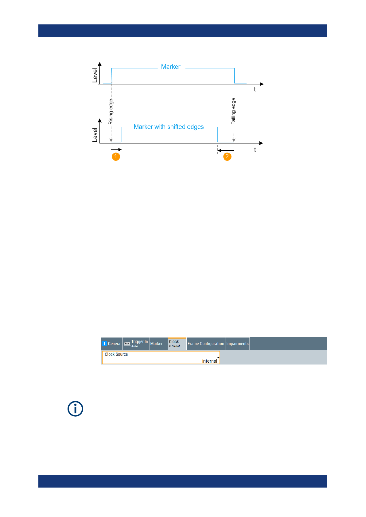
R&S®SMW-K149
Signal generation control
Clock settings
1 = Positive rise offset
2 = Positive fall offset
Remote command:
[:SOURce<hw>]:BB:HUWB:TRIGger:OUTPut<ch>:ROFFset on page 90
[:SOURce<hw>]:BB:HUWB:TRIGger:OUTPut<ch>:FOFFset on page 90
Marker x Delay
Delays the marker signal at the marker output relative to the signal generation start.
Variation of the parameter "Marker x Delay" causes signal recalculation.
Remote command:
[:SOURce<hw>]:BB:HUWB:TRIGger:OUTPut<ch>:DELay on page 89
4.4 Clock settings
Access:
► Select "Baseband > HRP UWB > Clock".
The tab provides settings necessary to select and configure the clock signal, like the
clock source and clock mode.
This section focuses on the available settings.
For information on how these settings affect the signal, refer to section "Basics on ..."
in the R&S SMW user manual.
45User Manual 1179.2077.02 ─ 04

R&S®SMW-K149
Signal generation control
Local and global connectors settings
Defining the clock
The provided clock signals are not dedicated to a particular connector. They can be
mapped to one or more USER x and T/M/C connectors.
Use the Local and global connectors settings to configure the signal mapping, the
polarity, the trigger threshold, and the input impedance of the input connectors.
To route and enable a trigger signal, perform the following general steps:
●
Define the signal source, that is select the "Clock > Source".
●
Define the connector where the selected signal is provided.
Use the Local and global connectors settings.
Settings:
Clock Source.................................................................................................................46
Clock Mode................................................................................................................... 46
Measured External Clock..............................................................................................46
Clock Source
Selects the clock source.
●
"Internal"
The instrument uses its internal clock reference.
●
"External Local Clock"
Option: R&S SMW-B10
The instrument expects an external clock reference at the local T/M/C connector.
Remote command:
[:SOURce<hw>]:BB:HUWB:CLOCk:SOURce on page 90
Clock Mode
Sets the type of externally supplied clock.
Remote command:
[:SOURce<hw>]:BB:HUWB:CLOCk:MODE on page 90
Measured External Clock
Provided for permanent monitoring of the enabled and externally supplied clock signal.
Remote command:
CLOCk:INPut:FREQuency?
4.5 Local and global connectors settings
Each of the "Trigger In", "Marker" and "Clock" dialogs and the "Trigger Marker Clock"
dialog provides a quick access to the related connector settings.
See also chapter "Local and global connectors settings" in the user manual.
46User Manual 1179.2077.02 ─ 04

R&S®SMW-K149
5 Remote control commands
Remote control commands
The following commands are required to generate signals with the HRP UWB option in
a remote environment. We assume that the R&S SMW has already been set up for
remote operation in a network as described in the R&S SMW documentation. A knowledge about the remote control operation and the SCPI command syntax is assumed.
Conventions used in SCPI command descriptions
For a description of the conventions used in the remote command descriptions, see
section "Remote-Control Commands" in the R&S SMW user manual.
Common suffixes
The following common suffixes are used in the remote commands:
Suffix Value range Description
SOURce<hw>
OUTPut<ch>
Using SCPI command aliases for advanced mode with multiple entities
You can address multiple entities configurations by using the SCPI commands starting
with the keyword SOURce or the alias commands starting with the keyword ENTity.
Note that the meaning of the keyword SOURce<hw> changes in the second case.
For details, see section "SCPI Command Aliases for Advanced Mode with Multiple
Entities" in the R&S SMW user manual.
Programming examples
This description provides simple programming examples. The purpose of the examples
is to present all commands for a given task. In real applications, one would rather
reduce the examples to an appropriate subset of commands.
The programming examples have been tested with a software tool which provides an
environment for the development and execution of remote tests. To keep the example
as simple as possible, only the "clean" SCPI syntax elements are reported. Non-executable command lines (e.g. comments) start with two // characters.
[1] to 4 Available baseband signals
Only SOURce1 possible, if the keyword ENTity is used
1 to 3 Available markers
At the beginning of the most remote control program, an instrument preset/reset is recommended to set the instrument to a definite state. The commands *RST and
SYSTem:PRESet are equivalent for this purpose. *CLS also resets the status registers
and clears the output buffer.
The following commands specific to the HRP UWB are described here:
● General commands.................................................................................................48
● Frame configuration commands..............................................................................53
● MAC header commands......................................................................................... 66
47User Manual 1179.2077.02 ─ 04

R&S®SMW-K149
5.1 General commands
Remote control commands
General commands
● Impairments commands..........................................................................................76
● Filter commands......................................................................................................76
● Clipping commands.................................................................................................81
● Trigger commands.................................................................................................. 82
● Marker commands.................................................................................................. 89
● Clock commands.....................................................................................................90
Example: To save the current configuration
SOURce1:BB:HUWB:SETTing:STORe "/var/user/my_settings"
*RST
SOURce1:BB:HUWB:SETTing:CATalog?
// Response: my_HUWB, HUWB
SOURce1:BB:HUWB:SETTing:LOAD "/var/user/HUWB"
SOURce1:BB:HUWB:STATe 1
SOURce1:BB:HUWB:SETTing:DEL "my_HUWB"
SOURce1:BB:HUWB:WAVeform:CREate "/var/user/my_HUWB_wv"
Example: To generate an HRP UWB signal
SOURce1:BB:HUWB:PRESet
SOURce1:BB:HUWB:STD HPRF
SOURce1:BB:HUWB:CNUMber 3
SOURce1:BB:HUWB:BWIDth?
// Response in MHz: 499.2
SOURce1:BB:HUWB:IINTerval 50
SOURce1:BB:HUWB:SLENgth 1
SOURce1:BB:HUWB:OSAMpling 4
SOURce1:BB:HUWB:SRATe:VARiation 500000
SOURce1:BB:HUWB:STATe 1
SOURce1:FREQuency:CW 4492800000
SOURce1:POWer:POWer -30
OUTPut1:STATe 1
Example: To generate a waveform
SOURce1:BB:HUWB:PRESet
SOURce1:BB:HUWB:STD HPRF
SOURce1:BB:HUWB:CNUMber 3
SOURce1:BB:HUWB:BWIDth?
// Response in MHz: 499.2
// To generate a waveform with fixed frame length of 2 ms.
SOURce:BB:HUWB:F2MS 1
// Sets the frame length to 2 ms
// Idle interval = 0µs is the default value if frame length 2 ms is activated
48User Manual 1179.2077.02 ─ 04

R&S®SMW-K149
Remote control commands
General commands
SOURce1:BB:HUWB:IINTerval?
// Response is 0
SOURce1:BB:HUWB:SLENgth 1
SOURce1:BB:HUWB:FILTer:OSAMpling OS_4
SOURce1:BB:HUWB:SRATe:VARiation 500000
SOURce1:BB:HUWB:STATe 1
SOURce1:FREQuency:CW 4492800000
SOURce1:POWer:POWer -30
OUTPut1:STATe 1
[:SOURce<hw>]:BB:HUWB:PRESet.................................................................................. 49
[:SOURce<hw>]:BB:HUWB:STATe.....................................................................................49
[:SOURce<hw>]:BB:HUWB:SETTing:CATalog.....................................................................50
[:SOURce<hw>]:BB:HUWB:SETTing:DELete......................................................................50
[:SOURce<hw>]:BB:HUWB:SETTing:LOAD........................................................................50
[:SOURce<hw>]:BB:HUWB:SETTing:STORe......................................................................50
[:SOURce<hw>]:BB:HUWB:SLENgth.................................................................................50
[:SOURce<hw>]:BB:HUWB:WAVeform:CREate...................................................................51
[:SOURce<hw>]:BB:HUWB:BWIDth?.................................................................................51
[:SOURce<hw>]:BB:HUWB:CNUMber................................................................................51
[:SOURce<hw>]:BB:HUWB:F2MS..................................................................................... 52
[:SOURce<hw>]:BB:HUWB:IINTerval................................................................................. 52
[:SOURce<hw>]:BB:HUWB:STD....................................................................................... 52
[:SOURce<hw>]:BB:HUWB:PRESet
Sets the parameters of the digital standard to their default values (*RST values specified for the commands).
Not affected is the state set with the command SOURce<hw>:BB:HUWB:STATe.
Example:
See Example "To generate an HRP UWB signal" on page 48.
Usage: Event
Manual operation: See "Set to Default" on page 14
[:SOURce<hw>]:BB:HUWB:STATe <HrpUwbState>
Activates the standard and deactivates all the other digital standards and digital modulation modes in the same path.
Parameters:
<HrpUwbState> 1 | ON | 0 | OFF
*RST: 0
Example: See Example "To generate an HRP UWB signal" on page 48.
Manual operation: See "State" on page 14
49User Manual 1179.2077.02 ─ 04

R&S®SMW-K149
Remote control commands
General commands
[:SOURce<hw>]:BB:HUWB:SETTing:CATalog
Queries the files with settings in the default directory. Listed are files with the file extension *.hrpuwb.
Example: See Example "To save the current configuration" on page 48.
Manual operation: See "Save/Recall" on page 14
[:SOURce<hw>]:BB:HUWB:SETTing:DELete <Filename>
Deletes the selected file from the default or the specified directory. Deleted are files
with extension *.hrpuwb.
Parameters:
<Filename> string
Example: See Example "To save the current configuration" on page 48.
Manual operation: See "Save/Recall" on page 14
[:SOURce<hw>]:BB:HUWB:SETTing:LOAD <Filename>
Loads the selected file from the default or the specified directory. Loaded are files with
extension *.hrpuwb.
Parameters:
<Filename> string
Example: See Example "To save the current configuration" on page 48.
Manual operation: See "Save/Recall" on page 14
[:SOURce<hw>]:BB:HUWB:SETTing:STORe <Filename>
Saves the current settings into the selected file; the file extension (*.hrpuwb) is
assigned automatically.
Parameters:
<Filename> string
Example: See Example "To save the current configuration" on page 48.
Manual operation: See "Save/Recall" on page 14
[:SOURce<hw>]:BB:HUWB:SLENgth <SLength>
Sets the sequence length of the signal in number of frames. The signal is calculated in
advance and output in the arbitrary waveform generator. The maximum number of
frames is calculated as follows:
Max. No. of Frames = Arbitrary waveform memory size/(sampling rate x 10 ms).
50User Manual 1179.2077.02 ─ 04

R&S®SMW-K149
Remote control commands
General commands
Parameters:
<SLength> integer
Range: 1 to 1024
*RST: 1
Example:
Manual operation: See "Sequence Length" on page 38
[:SOURce<hw>]:BB:HUWB:WAVeform:CREate
Saves the current settings as an ARB signal in a waveform file (*.wv).
Parameters:
<Filename> string
Example: See Example "To save the current configuration" on page 48.
Manual operation: See "Generate Waveform File" on page 15
[:SOURce<hw>]:BB:HUWB:BWIDth?
Queries the channel bandwidth.
Example:
Usage: Query only
Manual operation: See "Bandwidth" on page 15
SOURce1:BB:HUWB:SLENgth 4
Selects the generation of 4 frames.
<Filename>
See Example "To generate an HRP UWB signal" on page 48.
[:SOURce<hw>]:BB:HUWB:CNUMber <ChannelNumber>
Sets the channel number.
Parameters:
<ChannelNumber> integer
Range: 0 to 15
*RST: 0
Example: See Example "To configure non-HRP UWB frames"
on page 53.
Example: See Example "To configure HRP UWB 802.15.4z-BPRF frames"
on page 53.
Example: See Example "To configure HRP UWB 802.15.4z-HPRF frames"
on page 54.
Manual operation: See "Channel Number" on page 15
51User Manual 1179.2077.02 ─ 04

R&S®SMW-K149
Remote control commands
General commands
[:SOURce<hw>]:BB:HUWB:F2MS <Fixed2msFrame>
Sets the frame length of a generated waveform shorter than 2 ms to a fixed value of 2
ms.
If activated, the idle interval is set to 0.0 µs by default.
Parameters:
<Fixed2msFrame> 1 | ON | 0 | OFF
*RST: 0
Example: Example "To generate a waveform" on page 48
Manual operation: See "Fixed 2 ms Frame Length" on page 16
[:SOURce<hw>]:BB:HUWB:IINTerval <IInterval>
Sets the time of the interval separating two frames.
Parameters:
<IInterval> float
Range: 0 to 1000000
Increment: 0.1
*RST: 50
Default unit: µs
Example: See Example "To generate an HRP UWB signal" on page 48.
Manual operation: See "Idle Interval" on page 16
[:SOURce<hw>]:BB:HUWB:STD <Mode>
Sets the HRP UWB mode.
Parameters:
<Mode> NONHRP | HPRF | BPRF
NONHRP
Enables HRP non-ERDEV mode.
BPRF
Enables HRP-ERDEV base pulse repetition frequency (BPRF)
mode.
HPRF
Enables HRP-ERDEV higher pulse repetition frequency (HPRF)
mode.
*RST: NONHRP
Example: See Example "To generate an HRP UWB signal" on page 48.
Manual operation: See "Mode" on page 15
52User Manual 1179.2077.02 ─ 04

R&S®SMW-K149
5.2 Frame configuration commands
Remote control commands
Frame configuration commands
Example: To configure non-HRP UWB frames
SOURce1:BB:HUWB:PRESet
SOURce1:BB:HUWB:STD NONHRP
SOURce1:BB:HUWB:CNUMber 4
SOURce1:BB:HUWB:BWIDth?
// Response in MHz: 1331.2
SOURce1:BB:HUWB:FCONfig:CINDex CI_7
// Configure SYNC parameters.
SOURce1:BB:HUWB:FCONfig:SYNLength SL_16
SOURce1:BB:HUWB:FCONfig:DLENgth DL_16
SOURce1:BB:HUWB:FCONfig:SFDLength?
// Response: SFDL_8
// Configure physical data and physical header parameters.
SOURce1:BB:HUWB:FCONfig:DATA PN9
SOURce1:BB:HUWB:FCONfig:HOPBurst HB_8
SOURce1:BB:HUWB:FCONfig:CPBurst CPB_2
SOURce1:BB:HUWB:FCONfig:VRATe?
// Response: 0.5
SOURce1:BB:HUWB:FCONfig:CPBurst CPB_1
SOURce1:BB:HUWB:FCONfig:VRATe?
// Response: 1.0
SOURce1:BB:HUWB:FCONfig:MCS:STATe 1
SOURce1:BB:HUWB:FCONfig:MFL MFL_2
// Sets a MAC FCS length of two octets.
SOURce1:BB:HUWB:FCONfig:MPRF?
// Response in MHz: 15.6
SOURce1:BB:HUWB:FCONfig:DR?
// Response in Mb/s: 27.24
SOURce1:BB:HUWB:FCONfig:PHRBrate?
// Response in Mb/s: 0.85
SOURce1:BB:HUWB:FCONfig:DLENgth 127
Example: To configure HRP UWB 802.15.4z-BPRF frames
SOURce1:BB:HUWB:PRESet
SOURce1:BB:HUWB:STD BPRF
SOURce1:BB:HUWB:CNUMber 3
SOURce1:BB:HUWB:BWIDth?
// Response in MHz: 499.2
SOURce1:BB:HUWB:FCONfig:CINDex CI_7
// Configure SYNC parameters.
SOURce1:BB:HUWB:FCONfig:SYNLength SL_64
SOURce1:BB:HUWB:FCONfig:DLENgth DL_4
SOURce1:BB:HUWB:SFD SFD_2
53User Manual 1179.2077.02 ─ 04

R&S®SMW-K149
Remote control commands
Frame configuration commands
SOURce1:BB:HUWB:FCONfig:SFDLength?
// Response: SFDL_8
// Configure physical data and physical header parameters.
SOURce1:BB:HUWB:FCONfig:DATA PN9
SOURce1:BB:HUWB:FCONfig:HOPBurst HB_2
SOURce1:BB:HUWB:FCONfig:CPBurst CPB_8
SOURce1:BB:HUWB:FCONfig:VRATe?
// Response: 0.5
SOURce1:BB:HUWB:FCONfig:MCS:STATe 1
SOURce1:BB:HUWB:FCONfig:MFL MFL_2
// Sets a MAC FCS length of two octets.
SOURce1:BB:HUWB:FCONfig:MPRF?
// Response in MHz: 62.4
SOURce1:BB:HUWB:FCONfig:DR?
// Response in Mb/s: 6.81
SOURce1:BB:HUWB:FCONfig:PHRBrate?
// Response in Mb/s: 7.8
SOURce1:BB:HUWB:FCONfig:DLENgth 1
// Configure scrambled timestamp sequence (STS) parameters.
SOURce1:BB:HUWB:STS:PC SPC_3
SOURce1:BB:HUWB:STS:UPARt #H362EEB34C44FA8FBD37EC3CA,96
SOURce1:BB:HUWB:STS:CPARt #H1F9A3DE4,32
SOURce1:BB:HUWB:STS:KEY #H14148674D1D336AAF86050A814EB220F,128
SOURce1:BB:HUWB:STS:DLEN
// Response: DL_8
SOURce1:BB:HUWB:ASL ASL_64
SOURce1:BB:HUWB:ASN ASN_1
Example: To configure HRP UWB 802.15.4z-HPRF frames
SOURce1:BB:HUWB:PRESet
SOURce1:BB:HUWB:STD HPRF
SOURce1:BB:HUWB:CNUMber 7
SOURce1:BB:HUWB:BWIDth?
// Response in MHz: 1081.6
SOURce1:BB:HUWB:FCONfig:CINDex CI_8
// Configure SYNC parameters.
SOURce1:BB:HUWB:FCONfig:SYNLength SL_16
SOURce1:BB:HUWB:FCONfig:DLENgth DL_16
SOURce1:BB:HUWB:SFD SFD_4
SOURce1:BB:HUWB:FCONfig:SFDLength?
// Response: SFDL_32
// Configure physical data and physical header parameters.
SOURce1:BB:HUWB:FCONfig:DATA PN9
SOURce1:BB:HUWB:FCONfig:VRATe?
// Response: 0.5
SOURce1:BB:HUWB:CCCL CL7
SOURce1:BB:HUWB:FCONfig:MCS:STATe 1
54User Manual 1179.2077.02 ─ 04

R&S®SMW-K149
Remote control commands
Frame configuration commands
SOURce1:BB:HUWB:FCONfig:MFL MFL_2
// Sets a MAC FCS length of two octets.
SOURce1:BB:HUWB:FCONfig:MPRF?
// Response in MHz: 15.6
SOURce1:BB:HUWB:FCONfig:DR?
// Response in Mb/s: 31.2
SOURce1:BB:HUWB:FCONfig:PHRBrate?
// Response in Mb/s: 31.2
SOURce1:BB:HUWB:FCONfig:DALength 20
// Configure scrambled timestamp sequence (STS) parameters.
SOURce1:BB:HUWB:STS:PC SPC_3
SOURce1:BB:HUWB:STS:UPARt #H362EEB34C44FA8FBD37EC3CA,96
SOURce1:BB:HUWB:STS:CPARt #H1F9A3DE4,32
SOURce1:BB:HUWB:STS:KEY #H14148674D1D336AAF86050A814EB220F,128
SOURce1:BB:HUWB:STS:DLEN
// Response: DL_4
SOURce1:BB:HUWB:ASL ASL_256
SOURce1:BB:HUWB:ASN ASN_4
SOURce1:BB:HUWB:FCONfig:DALength?
// Response: 1023
// The data length is 1023 octets.
SOURce1:BB:HUWB:STS:PC SPC_2
SOURce1:BB:HUWB:FCONfig:ADDGap?
// Response: 0
// Set an additional gap of one octet.
SOURce1:BB:HUWB:FCONfig:ADDGap 1
// The maximum data length decreases to 1023 octets.
SOURce1:BB:HUWB:FCONfig:DALEngth?
// Response: 1022
Example: To modify and monitor frame lengths
SOURce1:BB:HUWB:STD NONHRP
SOURce1:BB:HUWB:FCONfig:DALength?
// Response in octets: "20"
SOURce1:BB:HUWB:FCONfig:FLENgth?
// Response in octets: "20"
// The frame length equals the data length of the physical header.
// Activate MAC frame check sequence field and set a length of four octets.
SOURce1:BB:HUWB:FCONfig:MCS:STATe 1
SOURce1:BB:HUWB:FCONfig:MFL MFL_4
SOURce1:BB:HUWB:FCONfig:FLENgth?
// Response in octets: "24"
Activate MAC header and use the default length of 11 octets.
SOURce1:BB:HUWB:MACHeader:STATe 1
SOURce1:BB:HUWB:FCONfig:FLENgth?
// Response in octets: "35"
55User Manual 1179.2077.02 ─ 04

R&S®SMW-K149
Remote control commands
Frame configuration commands
// You can further increase the frame length in mode 802.15.4z-HPRF.
SOURce1:BB:HUWB:STD HPRF
// Set the maximum data length to 1023 octets.
SOURce1:BB:HUWB:FCONfig:MDL MDL_1023
SOURce1:BB:HUWB:FCONfig:DALength 1023
SOURce1:BB:HUWB:FCONfig:FLENgth?
// Response in octets: "1038"
// Comprising 1023 octets data length, four octets FCS length and
// 11 octets MAC header length.
[:SOURce<hw>]:BB:HUWB:ASL........................................................................................56
[:SOURce<hw>]:BB:HUWB:ASN....................................................................................... 57
[:SOURce<hw>]:BB:HUWB:CCCL..................................................................................... 57
[:SOURce<hw>]:BB:HUWB:FCONfig:ADDGap................................................................... 57
[:SOURce<hw>]:BB:HUWB:FCONfig:CINDex..................................................................... 57
[:SOURce<hw>]:BB:HUWB:FCONfig:CPBurst.................................................................... 58
[:SOURce<hw>]:BB:HUWB:FCONfig:DATA........................................................................ 58
[:SOURce<hw>]:BB:HUWB:FCONfig:DATA:DSELection...................................................... 59
[:SOURce<hw>]:BB:HUWB:FCONfig:DATA:PATTern........................................................... 59
[:SOURce<hw>]:BB:HUWB:FCONfig:DR?..........................................................................59
[:SOURce<hw>]:BB:HUWB:FCONfig:DALEngth..................................................................60
[:SOURce<hw>]:BB:HUWB:FCONfig:DLENgth................................................................... 60
[:SOURce<hw>]:BB:HUWB:FCONfig:FLENgth?..................................................................60
[:SOURce<hw>]:BB:HUWB:FCONfig:HOPBurst..................................................................61
[:SOURce<hw>]:BB:HUWB:FCONfig:MCS:STATe...............................................................61
[:SOURce<hw>]:BB:HUWB:FCONfig:MDL..........................................................................61
[:SOURce<hw>]:BB:HUWB:FCONfig:MFL..........................................................................62
[:SOURce<hw>]:BB:HUWB:FCONfig:MPRF?..................................................................... 62
[:SOURce<hw>]:BB:HUWB:FCONfig:PHRBrate?................................................................ 62
[:SOURce<hw>]:BB:HUWB:FCONfig:SFDLength................................................................ 63
[:SOURce<hw>]:BB:HUWB:FCONfig:SYNLength................................................................63
[:SOURce<hw>]:BB:HUWB:FCONfig:VRATe?.....................................................................63
[:SOURce<hw>]:BB:HUWB:PHR:DRM...............................................................................64
[:SOURce<hw>]:BB:HUWB:SFD....................................................................................... 64
[:SOURce<hw>]:BB:HUWB:STS:CPARt.............................................................................64
[:SOURce<hw>]:BB:HUWB:STS:DLEN.............................................................................. 65
[:SOURce<hw>]:BB:HUWB:STS:KEY................................................................................ 65
[:SOURce<hw>]:BB:HUWB:STS:PC.................................................................................. 65
[:SOURce<hw>]:BB:HUWB:STS:UPARt............................................................................. 66
[:SOURce<hw>]:BB:HUWB:ASL <ActSegLength>
Sets the active segment length.
Parameters:
<ActSegLength> ASL_16 | ASL_32 | ASL_64 | ASL_128 | ASL_256 | ASL_512 |
ASL_1024 | ASL_2048
*RST: ASL_32
Example: See Example "To configure HRP UWB 802.15.4z-BPRF frames"
on page 53.
56User Manual 1179.2077.02 ─ 04

R&S®SMW-K149
Remote control commands
Frame configuration commands
Example: See Example "To configure HRP UWB 802.15.4z-HPRF frames"
on page 54.
Manual operation: See "Active Segment Length" on page 30
[:SOURce<hw>]:BB:HUWB:ASN <AcgSegNumber>
Sets the number of active segments.
Parameters:
<AcgSegNumber> ASN_1 | ASN_2 | ASN_3 | ASN_4
*RST: ASN_1
Example: See Example "To configure HRP UWB 802.15.4z-BPRF frames"
on page 53.
Example: See Example "To configure HRP UWB 802.15.4z-HPRF frames"
on page 54.
Manual operation: See "Number of Active Segments" on page 30
[:SOURce<hw>]:BB:HUWB:CCCL <CCCL>
Sets the constraint length of the convolutional code.
Parameters:
<CCCL> CL3 | CL7
*RST: CL3
Example: See Example "To configure HRP UWB 802.15.4z-HPRF frames"
on page 54.
Manual operation: See "Convolutional Code Constraint Length" on page 22
[:SOURce<hw>]:BB:HUWB:FCONfig:ADDGap <AdditionalGap>
Sets additional gap between payload and STS.
Parameters:
<AdditionalGap> integer
Range: 0 to 127
*RST: 0
Example: See Example "To configure non-HRP UWB frames" on page 53.
Manual operation: See "Additional Gap between Payload and STS" on page 30
[:SOURce<hw>]:BB:HUWB:FCONfig:CINDex <CodeIndex>
Sets the code index.
57User Manual 1179.2077.02 ─ 04

R&S®SMW-K149
Remote control commands
Frame configuration commands
Parameters:
<CodeIndex> CI_1 | CI_2 | CI_3 | CI_4 | CI_5 | CI_6 | CI_7 | CI_8 | CI_9 |
CI_10 | CI_11 | CI_12 | CI_13 | CI_14 | CI_15 | CI_16 | CI_17 |
CI_18 | CI_19 | CI_20 | CI_21 | CI_22 | CI_23 | CI_24 | CI_25 |
CI_26 | CI_27 | CI_28 | CI_29 | CI_30 | CI_31 | CI_32
*RST: CI_1
Example: See Example "To configure non-HRP UWB frames" on page 53.
Example: See Example "To configure HRP UWB 802.15.4z-BPRF frames"
on page 53.
Example: See Example "To configure HRP UWB 802.15.4z-HPRF frames"
on page 54.
Manual operation: See "Code Index" on page 17
[:SOURce<hw>]:BB:HUWB:FCONfig:CPBurst
Sets the chips per burst.
Parameters:
<ChipsPerBurst> CPB_1 | CPB_2 | CPB_4 | CPB_16 | CPB_8 | CPB_32 |
CPB_64 | CPB_128 | CPB_512
*RST: CPB_8
Example: See Example "To configure non-HRP UWB frames" on page 53.
Example: See Example "To configure HRP UWB 802.15.4z-BPRF frames"
on page 53.
Manual operation: See "Chips Per Burst" on page 22
[:SOURce<hw>]:BB:HUWB:FCONfig:DATA <DataSource>
Sets the data source for the payload data in a frame.
Parameters:
<DataSource> PN9 | PN11 | PN15 | PN20 | PN16 | PN21 | PN23 | ONE |
ZERO | DLISt | PATT
PNxx
The pseudo-random sequence generator is used as the data
source. There is a choice of different lengths of random
sequence.
DLISt
A data list is used. The data list is selected with the aid of command SOURce1:BB:HUWB:DATA DLISt.
ALL0 | ALL1
Internal 0 or 1 data is used.
PATT
Internal data is used. The bit pattern for the data is defined with
the aid of command SOURce1:BB:HUWB:DATA:PATTern.
<ChipsPerBurst>
58User Manual 1179.2077.02 ─ 04

R&S®SMW-K149
Remote control commands
Frame configuration commands
*RST: PN9
Example: See Example "To configure non-HRP UWB frames" on page 53.
Example: See Example "To configure HRP UWB 802.15.4z-BPRF frames"
on page 53.
Example: See Example "To configure HRP UWB 802.15.4z-HPRF frames"
on page 54.
Manual operation: See "Data Source" on page 21
[:SOURce<hw>]:BB:HUWB:FCONfig:DATA:DSELection <DSelection>
Selects an existing data list file from the default directory or from the specific directory.
The data list is only used, if the DLIS is selected.
Parameters:
<DSelection> string
Example: Load a data list saved in a file from the default directory.
SOURce1:BB:HUWB:FCONfig:DATA DLIS
SOURce1:BB:HUWB:FCONfig:DATA:DSELect
"/var/user/myUWB"
Manual operation: See "Data Source" on page 21
[:SOURce<hw>]:BB:HUWB:FCONfig:DATA:PATTern <DPattern>, <BitCount>
Sets the data pattern, if pattern is selected as the data source.
See [:SOURce<hw>]:BB:HUWB:FCONfig:DATA on page 58.
Parameters:
<DPattern> numeric
*RST: #H0
<BitCount> integer
Range: 1 to 64
*RST: 1
Example:
Manual operation: See "Data Source" on page 21
[:SOURce<hw>]:BB:HUWB:FCONfig:DR?
Queries the data rate.
SOURce1:BB:HUWB:FCONfig:DATA PATT
SOURce1:BB:HUWB:FCONfig:DATA:PATTern #H0,1
Example:
Example: See Example "To configure HRP UWB 802.15.4z-BPRF frames"
See Example "To configure non-HRP UWB frames" on page 53.
on page 53.
59User Manual 1179.2077.02 ─ 04

R&S®SMW-K149
Remote control commands
Frame configuration commands
Example: See Example "To configure HRP UWB 802.15.4z-HPRF frames"
on page 54.
Usage: Query only
Manual operation: See "Data Rate" on page 23
[:SOURce<hw>]:BB:HUWB:FCONfig:DALEngth <DLength>
Sets the data length of the physical header data in octets.
Parameters:
<DLength> integer
Range: 1 to 4096
*RST: 20
Example: See Example "To configure non-HRP UWB frames" on page 53.
Example: See Example "To configure HRP UWB 802.15.4z-BPRF frames"
on page 53.
Example: See Example "To configure HRP UWB 802.15.4z-HPRF frames"
on page 54.
Manual operation: See "Data Length" on page 23
[:SOURce<hw>]:BB:HUWB:FCONfig:DLENgth <DeltaLength>
Sets the delta length.
Parameters:
<DeltaLength> DL_4 | DL_16 | DL_64
*RST: DL_16
Example: See Example "To configure non-HRP UWB frames" on page 53.
Example: See Example "To configure HRP UWB 802.15.4z-BPRF frames"
on page 53.
Example: See Example "To configure HRP UWB 802.15.4z-HPRF frames"
on page 54.
Manual operation: See "Delta Length" on page 18
[:SOURce<hw>]:BB:HUWB:FCONfig:FLENgth?
Queries the frame length.
The frame length is the sum of the MAC header length, the MAC frame check
sequence (FCS) field length and the data length of the physical header.
Return values:
<FrameLength> integer
60User Manual 1179.2077.02 ─ 04

R&S®SMW-K149
Remote control commands
Frame configuration commands
Example: See Example "To modify and monitor frame lengths"
on page 55.
Usage: Query only
[:SOURce<hw>]:BB:HUWB:FCONfig:HOPBurst <HopBurst>
Sets the number of hop bursts.
Parameters:
<HopBurst> HB_2 | HB_8 | HB_32
*RST: HB_2
Example: See Example "To configure non-HRP UWB frames" on page 53.
Example: See Example "To configure HRP UWB 802.15.4z-BPRF frames"
on page 53.
Manual operation: See "Hop Bursts" on page 22
[:SOURce<hw>]:BB:HUWB:FCONfig:MCS:STATe
Activates MAC frame check sequence field.
Parameters:
<McsState> 1 | ON | 0 | OFF
*RST: 0
Example: See Example "To configure non-HRP UWB frames" on page 53.
Example: See Example "To configure HRP UWB 802.15.4z-BPRF frames"
on page 53.
Example: See Example "To configure HRP UWB 802.15.4z-HPRF frames"
on page 54.
Manual operation: See "MAC FCS" on page 22
[:SOURce<hw>]:BB:HUWB:FCONfig:MDL <MaxDataLen>
Sets the maximum data length for HPRF mode.
Parameters:
<MaxDataLen> MDL_1023 | MDL_2047 | MDL_4095
MDL_1023
1023 octets
MDL_2047
2047 octets
MDL_4095
4095 octets
*RST: MDL_1023
<McsState>
61User Manual 1179.2077.02 ─ 04

R&S®SMW-K149
Remote control commands
Frame configuration commands
Example: See Example "To modify and monitor frame lengths"
on page 55.
Manual operation: See "Maximum Data Length" on page 24
[:SOURce<hw>]:BB:HUWB:FCONfig:MFL <MacFCSLen>
Sets the length of the frame check sequence field.
Parameters:
<MacFCSLen> MFL_2 | MFL_4
MFL_2
Two octets
MFL_4
Four octets
*RST: MFL_2
Example: See Example "To modify and monitor frame lengths"
on page 55.
Manual operation: See "MAC FCS Length" on page 22
[:SOURce<hw>]:BB:HUWB:FCONfig:MPRF?
Queries the mean pulse repetition frequency (PRF).
Return values:
<MeanPRF> float
Example: See Example "To configure non-HRP UWB frames" on page 53.
Example: See Example "To configure HRP UWB 802.15.4z-BPRF frames"
on page 53.
Example: See Example "To configure HRP UWB 802.15.4z-HPRF frames"
on page 54.
Usage: Query only
Manual operation: See "Mean PRF" on page 23
[:SOURce<hw>]:BB:HUWB:FCONfig:PHRBrate?
Queries the physical header bit rate.
Example:
See Example "To configure non-HRP UWB frames" on page 53.
Example: See Example "To configure HRP UWB 802.15.4z-BPRF frames"
on page 53.
Example: See Example "To configure HRP UWB 802.15.4z-HPRF frames"
on page 54.
Usage: Query only
62User Manual 1179.2077.02 ─ 04

R&S®SMW-K149
Remote control commands
Frame configuration commands
Manual operation: See "PHR Bit Rate" on page 23
[:SOURce<hw>]:BB:HUWB:FCONfig:SFDLength <SFDLength>
Queries the symbol length of the start-of-frame delimiter (SFD).
The SFD length depends on the set SFD symbol sequence, see Table 5-1.
Parameters:
<SFDLength> SFDL_4 | SFDL_8 | SFDL_16 | SFDL_32 | SFDL_64
*RST: SFDL_8
Example: See Example "To configure non-HRP UWB frames" on page 53.
Example: See Example "To configure HRP UWB 802.15.4z-BPRF frames"
on page 53.
Example: See Example "To configure HRP UWB 802.15.4z-HPRF frames"
on page 54.
Manual operation: See "SFD Length" on page 19
[:SOURce<hw>]:BB:HUWB:FCONfig:SYNLength <SyncLength>
Sets the sync length.
Parameters:
<SyncLength> SL_16 | SL_24 | SL_32 | SL_48 | SL_64 | SL_96 | SL_128 |
SL_256 | SL_1024 | SL_4096
*RST: SL_64
Example: See Example "To configure non-HRP UWB frames" on page 53.
Example: See Example "To configure HRP UWB 802.15.4z-BPRF frames"
on page 53.
Example: See Example "To configure HRP UWB 802.15.4z-HPRF frames"
on page 54.
Manual operation: See "Sync Length" on page 18
[:SOURce<hw>]:BB:HUWB:FCONfig:VRATe?
Queries the viterbi rate for convolutional coding.
Example:
Example: See Example "To configure HRP UWB 802.15.4z-BPRF frames"
See Example "To configure non-HRP UWB frames" on page 53.
on page 53.
Example: See Example "To configure HRP UWB 802.15.4z-HPRF frames"
on page 54.
Usage: Query only
Manual operation: See "Viterbi Rate" on page 22
63User Manual 1179.2077.02 ─ 04

R&S®SMW-K149
Remote control commands
Frame configuration commands
[:SOURce<hw>]:BB:HUWB:PHR:DRM <DataRateMode>
Sets the data rate mode of the physical header.
Parameters:
<DataRateMode> BMLP | BMHP | HMLR | HMHR
*RST: BMLP
Example: See Example "To configure HRP UWB 802.15.4z-BPRF frames"
on page 53.
Example: See Example "To configure HRP UWB 802.15.4z-HPRF frames"
on page 54.
Manual operation: See "PHR Data Rate Mode" on page 23
[:SOURce<hw>]:BB:HUWB:SFD <SFDIndex>
Sets the start-of-frame delimiter (SFD) symbol sequence.
The indices represent SFD symbol sequences with SFD lengths as listed in Table 5-1.
Table 5-1: SFD: indices and lengths
Index SFD_0 SFD_1 SFD_2 SFD_3 SFD_4 SFD_5 SFD_6 SFD_7 SFD_8
SFD 0 1 2 3 4 User1 User2 User3 Legacy
SFD length 8 4 8 16 32 8 16 32 8
Parameters:
<SFDIndex> SFD_0 | SFD_1 | SFD_2 | SFD_3 | SFD_4 | SFD_5 | SFD_6 |
SFD_7 | SFD_8
*RST: SFD_5
Example: See Example "To configure HRP UWB 802.15.4z-BPRF frames"
on page 53.
Example: See Example "To configure HRP UWB 802.15.4z-HPRF frames"
on page 54.
Manual operation: See "SFD" on page 19
[:SOURce<hw>]:BB:HUWB:STS:CPARt <CounterPart>
Sets the counter part of the V valued. The value is a 32-bit value in hexadecimal representation.
Parameters:
<CounterPart> integer
Example: See Example "To configure HRP UWB 802.15.4z-BPRF frames"
on page 53.
Example: See Example "To configure HRP UWB 802.15.4z-HPRF frames"
on page 54.
64User Manual 1179.2077.02 ─ 04

R&S®SMW-K149
Remote control commands
Frame configuration commands
Manual operation: See "VCounter(hex)" on page 29
[:SOURce<hw>]:BB:HUWB:STS:DLEN <DeltaLength>
Queries the delta length of the scrambled timestamp sequence (STS).
Parameters:
<DeltaLength> DL_4 | DL_8
*RST: DL_4
Example: See Example "To configure HRP UWB 802.15.4z-BPRF frames"
on page 53.
Example: See Example "To configure HRP UWB 802.15.4z-HPRF frames"
on page 54.
Manual operation: See "Delta Length" on page 29
[:SOURce<hw>]:BB:HUWB:STS:KEY <Key>
Sets the key value of the scrambled timestamp sequence (STS). The value is a 128-bit
value in hexadecimal representation.
Parameters:
<Key> integer
Example: See Example "To configure HRP UWB 802.15.4z-BPRF frames"
on page 53.
Example: See Example "To configure HRP UWB 802.15.4z-HPRF frames"
on page 54.
Manual operation: See "Key(hex)" on page 29
[:SOURce<hw>]:BB:HUWB:STS:PC <SPC>
Sets the scrambled timestamp sequence (STS) packet configuration.
Parameters:
<SPC> SPC_0 | SPC_1 | SPC_2 | SPC_3
*RST: SPC_0
Example: See Example "To configure HRP UWB 802.15.4z-BPRF frames"
on page 53.
Example: See Example "To configure HRP UWB 802.15.4z-HPRF frames"
on page 54.
Manual operation: See "STS Packet Configuration" on page 17
65User Manual 1179.2077.02 ─ 04

R&S®SMW-K149
Remote control commands
MAC header commands
[:SOURce<hw>]:BB:HUWB:STS:UPARt <UpperPart>
Sets the upper part of the V value. The value is a 96-bit value in hexadecimal representation.
Parameters:
<UpperPart> integer
Example: See Example "To configure HRP UWB 802.15.4z-BPRF frames"
on page 53.
Example: See Example "To configure HRP UWB 802.15.4z-HPRF frames"
on page 54.
Manual operation: See "VUpper96(hex)" on page 29
5.3
MAC header commands
Example: To configure MAC header information
SOURce1:BB:HUWB:MACHeader:STATe 0
// Configure frame control field parameters.
SOURce1:BB:HUWB:MACHeader:LFRControl L2
SOURce1:BB:HUWB:MACHeader:CTRL 34913
SOURce1:BB:HUWB:MACHeader:FTYPe 1
SOURce1:BB:HUWB:MACHeader:SEENabled 0
SOURce1:BB:HUWB:MACHeader:FPENding 0
SOURce1:BB:HUWB:MACHeader:AR 1
SOURce1:BB:HUWB:MACHeader:PIDComp 1
SOURce1:BB:HUWB:MACHeader:REServed 0
SOURce1:BB:HUWB:MACHeader:SENSupp 0
SOURce1:BB:HUWB:MACHeader:IEPResent 0
SOURce1:BB:HUWB:MACHeader:DADMode 2
SOURce1:BB:HUWB:MACHeader:FVERsion 0
SOURce1:BB:HUWB:MACHeader:SADMode 2
// Configure sequence number field parameters.
SOURce1:BB:HUWB:MACHeader:LSEQnumber L1
SOURce1:BB:HUWB:MACHeader:SEQNumber 1
// Configure destination PAN ID field parameters.
SOURce1:BB:HUWB:MACHeader:LDEPanid L2
SOURce1:BB:HUWB:MACHeader:DPANid 43981
// Configure destination address field parameters.
SOURce1:BB:HUWB:MACHeader:LDADdress L2
SOURce1:BB:HUWB:MACHeader:DADD 4660
// Configure source PAN ID field parameters.
SOURce1:BB:HUWB:MACHeader:LSOPanid L2
66User Manual 1179.2077.02 ─ 04

R&S®SMW-K149
Remote control commands
MAC header commands
SOURce1:BB:HUWB:MACHeader:SPANid 44015
// Configure source address field parameters.
SOURce1:BB:HUWB:MACHeader:LSADdress L2
SOURce1:BB:HUWB:MACHeader:SADD 22136
// Activate MAC header information.
SOURce1:BB:HUWB:MACHeader:STATe 1
// Query MAC header information.
SOURce1:BB:HUWB:MACHeader:STRing?
// Response: "11 Octets: 8861-01-ABCD-1234-ABEF-5678"
[:SOURce<hw>]:BB:HUWB:MACHeader:AR.......................................................................67
[:SOURce<hw>]:BB:HUWB:MACHeader:CTRL...................................................................68
[:SOURce<hw>]:BB:HUWB:MACHeader:DAD2...................................................................68
[:SOURce<hw>]:BB:HUWB:MACHeader:DAD3...................................................................68
[:SOURce<hw>]:BB:HUWB:MACHeader:DAD4...................................................................68
[:SOURce<hw>]:BB:HUWB:MACHeader:DADD..................................................................68
[:SOURce<hw>]:BB:HUWB:MACHeader:DADMode............................................................ 68
[:SOURce<hw>]:BB:HUWB:MACHeader:DPANid................................................................69
[:SOURce<hw>]:BB:HUWB:MACHeader:FPENding............................................................ 69
[:SOURce<hw>]:BB:HUWB:MACHeader:FTYPe................................................................. 69
[:SOURce<hw>]:BB:HUWB:MACHeader:FVERsion.............................................................70
[:SOURce<hw>]:BB:HUWB:MACHeader:IEPResent............................................................70
[:SOURce<hw>]:BB:HUWB:MACHeader:LDADdress...........................................................70
[:SOURce<hw>]:BB:HUWB:MACHeader:LDEPanid.............................................................71
[:SOURce<hw>]:BB:HUWB:MACHeader:LFRControl...........................................................71
[:SOURce<hw>]:BB:HUWB:MACHeader:LSADdress...........................................................71
[:SOURce<hw>]:BB:HUWB:MACHeader:LSEPanid.............................................................72
[:SOURce<hw>]:BB:HUWB:MACHeader:LSEQnumber........................................................72
[:SOURce<hw>]:BB:HUWB:MACHeader:LSOPanid............................................................ 72
[:SOURce<hw>]:BB:HUWB:MACHeader:PIDComp............................................................. 73
[:SOURce<hw>]:BB:HUWB:MACHeader:REServed............................................................ 73
[:SOURce<hw>]:BB:HUWB:MACHeader:SAD2...................................................................73
[:SOURce<hw>]:BB:HUWB:MACHeader:SAD3...................................................................73
[:SOURce<hw>]:BB:HUWB:MACHeader:SAD4...................................................................73
[:SOURce<hw>]:BB:HUWB:MACHeader:SADD.................................................................. 73
[:SOURce<hw>]:BB:HUWB:MACHeader:SADMode............................................................ 74
[:SOURce<hw>]:BB:HUWB:MACHeader:SEENabled.......................................................... 74
[:SOURce<hw>]:BB:HUWB:MACHeader:SENSupp.............................................................74
[:SOURce<hw>]:BB:HUWB:MACHeader:SEQNumber.........................................................75
[:SOURce<hw>]:BB:HUWB:MACHeader:SPANid................................................................75
[:SOURce<hw>]:BB:HUWB:MACHeader:STATe..................................................................75
[:SOURce<hw>]:BB:HUWB:MACHeader:STRing?...............................................................75
[:SOURce<hw>]:BB:HUWB:MACHeader:AR <AR>
Sets the bit in the AR field.
67User Manual 1179.2077.02 ─ 04

R&S®SMW-K149
Remote control commands
MAC header commands
Parameters:
<AR> integer
Range: 0 to 1
*RST: 0
Example: See Example "To configure MAC header information"
on page 66.
Manual operation: See "AR" on page 26
[:SOURce<hw>]:BB:HUWB:MACHeader:CTRL
Sets the input value of the frame control field. The value is an 8-bit or 16-bit value in
hexadecimal representation.
Parameters:
<FrameControl> integer
Range: 0 to 65535
*RST: 0
Example: See Example "To configure MAC header information"
on page 66.
Manual operation: See "Frame Control" on page 25
[:SOURce<hw>]:BB:HUWB:MACHeader:DAD2 <DestAddr2>
[:SOURce<hw>]:BB:HUWB:MACHeader:DAD3 <DestAddr3>
[:SOURce<hw>]:BB:HUWB:MACHeader:DAD4 <DestAddr4>
[:SOURce<hw>]:BB:HUWB:MACHeader:DADD <DestinationAddr>
DADD requires destination address length of two or eight octets.
DAD2, DAD3 and DAD4 require destination address length of eight octets. See [:
SOURce<hw>]:BB:HUWB:MACHeader:LDADdress on page 70.
Sets the first, second, third and fourth input value of the destination address field.
<FrameControl>
Parameters:
<DestinationAddr> integer
Range: 0 to 65535
*RST: 0
Example: See Example "To configure MAC header information"
on page 66.
Manual operation: See "Destination Address" on page 28
[:SOURce<hw>]:BB:HUWB:MACHeader:DADMode <DestAddrMode>
Requires frame control length of two octets. See [:SOURce<hw>]:BB:HUWB:
MACHeader:LFRControl on page 71.
Sets bits of the destination addressing mode.
68User Manual 1179.2077.02 ─ 04

R&S®SMW-K149
Remote control commands
MAC header commands
Parameters:
<DestAddrMode> integer
Range: 0 to 3
*RST: 0
Example: See Example "To configure MAC header information"
on page 66.
Manual operation: See "Destination Addressing Mode" on page 27
[:SOURce<hw>]:BB:HUWB:MACHeader:DPANid
Sets the length and the input value of the destination PAN ID field.
Parameters:
<DestinationPanI> integer
Range: 0 to 65535
*RST: 0
Manual operation: See "Destination PAN ID" on page 27
[:SOURce<hw>]:BB:HUWB:MACHeader:FPENding <FramePending>
Sets the bit in the frame pending field.
Parameters:
<FramePending> integer
Range: 0 to 1
*RST: 0
Example: See Example "To configure MAC header information"
on page 66.
Manual operation: See "Frame Pending" on page 26
<DestinationPanI>
[:SOURce<hw>]:BB:HUWB:MACHeader:FTYPe <FrameType>
Sets the bits in the frame type field. The value is a 3-bit value.
Parameters:
<FrameType> integer
Range: 0 to 7
*RST: 0
Example: See Example "To configure MAC header information"
on page 66.
Manual operation: See "Frame Type" on page 25
69User Manual 1179.2077.02 ─ 04

R&S®SMW-K149
Remote control commands
MAC header commands
[:SOURce<hw>]:BB:HUWB:MACHeader:FVERsion <FrameVersion>
Requires frame control length of two octets. See [:SOURce<hw>]:BB:HUWB:
MACHeader:LFRControl on page 71.
Sets the bits in the frame version field. The value is a 2-bit value.
Parameters:
<FrameVersion> integer
Range: 0 to 3
*RST: 0
Example: See Example "To configure MAC header information"
on page 66.
Manual operation: See "Frame Version" on page 27
[:SOURce<hw>]:BB:HUWB:MACHeader:IEPResent <IePresent>
Requires frame control length of two octets. See [:SOURce<hw>]:BB:HUWB:
MACHeader:LFRControl on page 71.
Sets the bit in the information element (IE) present field.
Parameters:
<IePresent> integer
Range: 0 to 1
*RST: 0
Example: See Example "To configure MAC header information"
on page 66.
Manual operation: See "IE Present" on page 26
[:SOURce<hw>]:BB:HUWB:MACHeader:LDADdress <LenDestAddr>
Sets the length of the destination address field. You can set lengths of zero octets, two
octets or eight octets.
Parameters:
<LenDestAddr> L0 | L2 | L8
L0
Sets destination address length to zero octets.
L2
Sets destination address length to two octets.
L8
Sets destination address length to eight octets.
*RST: L0
Example: See Example "To configure MAC header information"
on page 66.
Manual operation: See "Destination Address" on page 28
70User Manual 1179.2077.02 ─ 04

R&S®SMW-K149
Remote control commands
MAC header commands
[:SOURce<hw>]:BB:HUWB:MACHeader:LDEPanid <LenDestPanId>
Sets the length of the destination PAN ID field. You can set lengths of zero octets or
two octets.
Parameters:
<LenDestPanId> L0 | L2
L0
Sets destination PAN ID length to zero octets.
L2
Sets destination PAN ID length to two octets.
*RST: 0
Example: See Example "To configure MAC header information"
on page 66.
Manual operation: See "Destination PAN ID" on page 27
[:SOURce<hw>]:BB:HUWB:MACHeader:LFRControl <LenFrameControl>
Sets the length of the frame control field. You can set lengths of one octet or two
octets.
Parameters:
<LenFrameControl> L1 | L2
L1
Sets frame control length to one octet.
L2
Sets frame control length to two octets.
*RST: 0
Example: See Example "To configure MAC header information"
on page 66.
Manual operation: See "Frame Control" on page 25
[:SOURce<hw>]:BB:HUWB:MACHeader:LSADdress <LenSrcAddress>
Sets the length of the source address field. You can set lengths of zero octets, two
octets or eight octets.
Parameters:
<LenSrcAddress> L0 | L2 | L8
L0
Sets source address length to zero octets.
L2
Sets source address length to two octets.
L8
Sets source address length to eight octets.
*RST: L0
71User Manual 1179.2077.02 ─ 04

R&S®SMW-K149
Remote control commands
MAC header commands
Example: See Example "To configure MAC header information"
on page 66.
Manual operation: See "Source Address" on page 28
[:SOURce<hw>]:BB:HUWB:MACHeader:LSEPanid <LenSourcePanId>
Activates or deactivates the source PAN ID information.
Parameters:
<LenSourcePanId> 0 | 1 | OFF | ON
*RST: 0
[:SOURce<hw>]:BB:HUWB:MACHeader:LSEQnumber
Sets the length of the sequence number field. You can set zero octets or one octet.
Parameters:
<LenSeqNumber> L0 | L1
L0
Sets the sequence number length to zero octets.
L1
Sets the sequence number length to one octet.
*RST: 0
Example: See Example "To configure MAC header information"
on page 66.
Manual operation: See "Sequence Number" on page 27
[:SOURce<hw>]:BB:HUWB:MACHeader:LSOPanid <LenSourcePanId>
Sets the length of the source PAN ID field. You can set lengths of zero octets or two
octets.
Parameters:
<LenSourcePanId> L0 | L2
L0
Sets source PAN ID length to zero octets.
L2
Sets source PAN ID length to two octets.
*RST: 0
<LenSeqNumber>
Example: See Example "To configure MAC header information"
on page 66.
Manual operation: See "Source PAN ID" on page 28
72User Manual 1179.2077.02 ─ 04

R&S®SMW-K149
Remote control commands
MAC header commands
[:SOURce<hw>]:BB:HUWB:MACHeader:PIDComp <PanIdCompress>
Sets the bit in the PAN ID compression field.
Parameters:
<PanIdCompress> integer
Range: 0 to 1
*RST: 0
Example: See Example "To configure MAC header information"
on page 66.
Manual operation: See "PAN ID Compression" on page 26
[:SOURce<hw>]:BB:HUWB:MACHeader:REServed <Reserved>
Sets a reserved bit for future use.
Parameters:
<Reserved> integer
Range: 0 to 1
*RST: 0
Example: See Example "To configure MAC header information"
on page 66.
Manual operation: See "Reserved" on page 26
[:SOURce<hw>]:BB:HUWB:MACHeader:SAD2 <SourceAddress2>
[:SOURce<hw>]:BB:HUWB:MACHeader:SAD3 <SourceAddress3>
[:SOURce<hw>]:BB:HUWB:MACHeader:SAD4 <SourceAddress4>
[:SOURce<hw>]:BB:HUWB:MACHeader:SADD <SourceAddress>
SADD requires source address length of two or eight octets.
SAD2, SAD3 and SAD4 require source address lengths of eight octets.
See [:SOURce<hw>]:BB:HUWB:MACHeader:LSADdress on page 71.
Sets the first, second, third and fourth input value of the source address field.
Parameters:
<SourceAddress> integer
Range: 0 to 65535
*RST: 0
Example: See Example "To configure MAC header information"
on page 66.
Manual operation: See "Source Address" on page 28
73User Manual 1179.2077.02 ─ 04

R&S®SMW-K149
Remote control commands
MAC header commands
[:SOURce<hw>]:BB:HUWB:MACHeader:SADMode <SrcAddrMode>
Requires frame control length of two octets. See [:SOURce<hw>]:BB:HUWB:
MACHeader:LFRControl on page 71.
Sets the bits in the source addressing mode field. The value is a 2-bit value.
Parameters:
<SrcAddrMode> integer
Range: 0 to 3
*RST: 0
Example: See Example "To configure MAC header information"
on page 66.
Manual operation: See "Source Addressing Mode" on page 27
[:SOURce<hw>]:BB:HUWB:MACHeader:SEENabled <SecurityEnabled>
Sets the bit in the security enabled field.
Parameters:
<SecurityEnabled> integer
Range: 0 to 1
*RST: 0
Example: See Example "To configure MAC header information"
on page 66.
Manual operation: See "Security Enabled" on page 26
[:SOURce<hw>]:BB:HUWB:MACHeader:SENSupp <SeqNumbSuppr>
Requires frame control length of two octets. See [:SOURce<hw>]:BB:HUWB:
MACHeader:LFRControl on page 71.
Sets the bit in the sequence number suppression field.
Parameters:
<SeqNumbSuppr> integer
Range: 0 to 1
*RST: 0
Example: See Example "To configure MAC header information"
on page 66.
Manual operation: See "Sequence Number Suppression" on page 26
74User Manual 1179.2077.02 ─ 04

R&S®SMW-K149
Remote control commands
MAC header commands
[:SOURce<hw>]:BB:HUWB:MACHeader:SEQNumber <SequenceNumber>
Parameters:
<SequenceNumber> integer
Range: 0 to 65535
*RST: 0
Manual operation: See "Sequence Number" on page 27
[:SOURce<hw>]:BB:HUWB:MACHeader:SPANid <SourcePanId>
Sets the input value of the source PAN ID field. The value is a 16-bit value in hexadecimal representation.
Parameters:
<SourcePanId> integer
Range: 0 to 65535
*RST: 0
Example: See Example "To configure MAC header information"
on page 66.
Manual operation: See "Source PAN ID" on page 28
[:SOURce<hw>]:BB:HUWB:MACHeader:STATe <State>
Activates or deactivates MAC header information.
Parameters:
<State> 1 | ON | 0 | OFF
*RST: 0
Example: See Example "To configure MAC header information"
on page 66.
Manual operation: See "MAC Header" on page 25
[:SOURce<hw>]:BB:HUWB:MACHeader:STRing?
Queries the length of the MAC header and the MAC address in hexadecimal format.
Return values:
<String> string
Example: See Example "To configure MAC header information"
on page 66.
Usage: Query only
Manual operation: See "MAC Header" on page 22
75User Manual 1179.2077.02 ─ 04

R&S®SMW-K149
5.4 Impairments commands
Remote control commands
Filter commands
Example: To impair an HRP UWB signal
// Configure symbol timing error in ppm.
SOURce1:BB:HUWB:IMPairments:STERror 10
// Configure frequency offset in Hz.
SOURce1:BB:HUWB:IMPairments:FOFFset 25000
// Activate impairing the signal.
SOURce1:BB:HUWB:IMPairments:STATe 1
[:SOURce<hw>]:BB:HUWB:IMPairments:FOFFset.............................................................. 76
[:SOURce<hw>]:BB:HUWB:IMPairments:STATe..................................................................76
[:SOURce<hw>]:BB:HUWB:IMPairments:CCERror..............................................................76
[:SOURce<hw>]:BB:HUWB:IMPairments:FOFFset <FOffset>
[:SOURce<hw>]:BB:HUWB:IMPairments:STATe <State>
[:SOURce<hw>]:BB:HUWB:IMPairments:CCERror <STError>
Sets the chip clock error of the impairment symbols.
Parameters:
<STError> integer
Range: -300 to 300
*RST: 0
Example: See Example "To impair an HRP UWB signal" on page 76.
Manual operation: See "Chip Clock Error" on page 31
5.5 Filter commands
Example: To configure filter settings
// ******************************************************************
// Configure filter type, roll-off factor, oversampling and output
// sample rate.
// ******************************************************************
SOURce1:BB:HUWB:FILTer:TYPE RCOS
SOURce1:BB:HUWB:FILTer:ROFactor 0.5
// Set an oversampling factor of 1.
SOURce1:BB:HUWB:FILTer:OSAMP OS_1
SOURce1:BB:HUWB:FILTer:SRATe:VARiation?
// Response in Hz: 499200000
SOURce1:BB:HUWB:FILTer:OSAMP OS_2
SOURce1:BB:HUWB:FILTer:SRATe:VARiation?
// Response in Hz: 998400000
76User Manual 1179.2077.02 ─ 04

R&S®SMW-K149
Remote control commands
Filter commands
// ******************************************************************
// Configure an LTE filter.
// ******************************************************************
SOURce1:BB:HUWB:FILTer:TYPE LTEF
SOURce1:BB:HUWB:FILTer:PARameter:LTE:OPTimization EVM
// LTE filter is optimized for EVM performance.
SOURce1:BB:HUWB:FILTer:PARameter:LTE:COFFactor 0.1
SOURce1:BB:HUWB:FILTer:PARameter:LTE:ROFactor -0.2
// Change LTE filter optimization for ACP performance.
SOURce1:BB:HUWB:FILTer:PARameter:LTE:OPTimization ACP
SOURce1:BB:HUWB:FILTer:PARameter:LTE:COFS 0.34
// Check, if the internal filter is active.
SOURce1:BB:HUWB:FILTer:AUTO?
// Response: 0
// The internal filter is not active.
// ******************************************************************
// Configure a user-defined filter.
// ******************************************************************
SOURce1:BB:HUWB:FILTer:TYPE USER
// Load the file, that specifies the filter. You can load files with
// extension *.dat or *.vaf.
SOURce1:BB:HUWB:FILTer:PARameter:USER "/var/user/my_filter"
// Loads a user-defined filter as defined in file "my_filter.dat".
[:SOURce<hw>]:BB:HUWB:FILTer:TYPE............................................................................77
[:SOURce<hw>]:BB:HUWB:FILTer:OSAMpling....................................................................78
[:SOURce<hw>]:BB:HUWB:FILTer:PARameter:APCo25.......................................................78
[:SOURce<hw>]:BB:HUWB:FILTer:PARameter:COSine....................................................... 78
[:SOURce<hw>]:BB:HUWB:FILTer:PARameter:GAUSs........................................................78
[:SOURce<hw>]:BB:HUWB:FILTer:PARameter:LPASs......................................................... 78
[:SOURce<hw>]:BB:HUWB:FILTer:PARameter:LPASsevm...................................................78
[:SOURce<hw>]:BB:HUWB:FILTer:PARameter:PGAuss.......................................................78
[:SOURce<hw>]:BB:HUWB:FILTer:PARameter:RCOSine.....................................................78
[:SOURce<hw>]:BB:HUWB:FILTer:PARameter:SPHase.......................................................78
[:SOURce<hw>]:BB:HUWB:FILTer:PARameter:LTE:COFFactor............................................ 79
[:SOURce<hw>]:BB:HUWB:FILTer:PARameter:COSine:COFS............................................. 79
[:SOURce<hw>]:BB:HUWB:FILTer:PARameter:LTE:COFS................................................... 79
[:SOURce<hw>]:BB:HUWB:FILTer:PARameter:LTE:OPTimization.........................................79
[:SOURce<hw>]:BB:HUWB:FILTer:PARameter:LTE:ROFactor.............................................. 80
[:SOURce<hw>]:BB:HUWB:FILTer:PARameter:USER..........................................................80
[:SOURce<hw>]:BB:HUWB:SRATe:VARiation.....................................................................80
[:SOURce<hw>]:BB:HUWB:FILTer:TYPE <Type>
Selects the baseband filter type.
77User Manual 1179.2077.02 ─ 04

R&S®SMW-K149
Remote control commands
Filter commands
Parameters:
<Type> RCOSine | COSine | GAUSs | LGAuss | CONE | COF705 |
COEQualizer | COFequalizer | C2K3x | APCO25 | SPHase |
RECTangle | USER | PGAuss | LPASs | DIRac | ENPShape |
EWPShape | LTEFilter | LPASSEVM | APCO25Hcpm |
APCO25Lsm | HRP
*RST: HRP
Example: See Example "To configure filter settings" on page 76.
Manual operation: See "Filter" on page 32
[:SOURce<hw>]:BB:HUWB:FILTer:OSAMpling <OverSampling>
Sets the oversampling factor of the generated waveform.
A reduced sample rate saves significantly the amount of memory or allows an
increased signal cycle time, and vice versa.
Parameters:
<OverSampling> OS_1 | OS_2 | OS_3 | OS_4 | OS_5 | OS_6 | OS_7 | OS_8
*RST: OS_1
*RST: OS_1 (R&S SMW-K525)/OS_4 (R&S SMW-K527)
Example: See Example "To configure filter settings" on page 76.
Manual operation: See "Oversampling" on page 36
[:SOURce<hw>]:BB:HUWB:FILTer:PARameter:APCo25 <Apco25>
[:SOURce<hw>]:BB:HUWB:FILTer:PARameter:COSine <Cosine>
[:SOURce<hw>]:BB:HUWB:FILTer:PARameter:GAUSs <Gauss>
[:SOURce<hw>]:BB:HUWB:FILTer:PARameter:LPASs <LPass>
[:SOURce<hw>]:BB:HUWB:FILTer:PARameter:LPASsevm <CutoffFrequency>
[:SOURce<hw>]:BB:HUWB:FILTer:PARameter:PGAuss <PGauss>
[:SOURce<hw>]:BB:HUWB:FILTer:PARameter:RCOSine <RCosine>
[:SOURce<hw>]:BB:HUWB:FILTer:PARameter:SPHase <SPhase>
Sets the filter parameter.
Filter type Parameter Parameter name Min Max Incre-
ment
APCO25
COSine
GAUSs
LPASs
Rolloff factor
Rolloff factor
BxT
Cutoff frequency
<Apco25>
<Cosine>
<Gauss>
<LPass>
0.05 0.99 0.01 0.2
0 1 0.01 0.1
0.15 2.5 0.01 0.5
0.02 2 0.01 0.34
Default
LPASSEVM
PGAuss
Cutoff frequency
BxT
<CutoffFrequency>
<PGauss>
0.05 2 0.01 0.29
0.15 2.5 0.01 0.5
78User Manual 1179.2077.02 ─ 04

R&S®SMW-K149
Remote control commands
Filter commands
Filter type Parameter Parameter name Min Max Incre-
ment
RCOSine
SPHase
Rolloff factor
BxT
<RCosine>
<SPhase>
0 1 0.01 0.22
0.15 2.5 0.01 2
Parameters:
<SPhase> float
Range: 0.15 to 2.5
Increment: 0.01
*RST: 2
Example: See Example "To configure filter settings" on page 76.
Manual operation: See "Roll Off Factor or BxT" on page 35
[:SOURce<hw>]:BB:HUWB:FILTer:PARameter:LTE:COFFactor
<CutoffFactor>
Sets the cut-off frequency factor for the LTE filter type.
Parameters:
<CutoffFactor> float
Range: 0.02 to 2
Increment: 0.001
*RST: 0.34
Default
Example: See Example "To configure filter settings" on page 76.
Manual operation: See "Cut Off Frequency Factor" on page 36
[:SOURce<hw>]:BB:HUWB:FILTer:PARameter:COSine:COFS <Cofs>
[:SOURce<hw>]:BB:HUWB:FILTer:PARameter:LTE:COFS <CutOffFreqShift>
Sets the cut-off frequency shift of the applied filter.
Parameters:
<CutOffFreqShift> float
Range: -1 to 1
Increment: 0.01
*RST: -0.2
Example: See Example "To configure filter settings" on page 76.
Manual operation: See "Cut Off Frequency Shift" on page 35
[:SOURce<hw>]:BB:HUWB:FILTer:PARameter:LTE:OPTimization <Optimization>
Defines the applied LTE filter.
Parameters:
<Optimization> EVM | STD | ACP | ACPN | BENU
*RST: EVM
79User Manual 1179.2077.02 ─ 04

R&S®SMW-K149
Remote control commands
Filter commands
Example: See Example "To configure filter settings" on page 76.
Manual operation: See "Optimization" on page 33
[:SOURce<hw>]:BB:HUWB:FILTer:PARameter:LTE:ROFactor <RollOffFactor>
Sets the roll-off factor for the LTE filter type.
Parameters:
<RollOffFactor> float
Range: 0 to 1
Increment: 0.01
*RST: 0.1
Example: See Example "To configure filter settings" on page 76.
Manual operation: See "Roll Off Factor or BxT" on page 35
[:SOURce<hw>]:BB:HUWB:FILTer:PARameter:USER
Loads the file from the default or the specified directory.
Loaded are files with extension *.vaf or *.dat.
Parameters:
<Filename> string
Example: See Example "To configure filter settings" on page 76.
Manual operation: See "Load User Filter" on page 34
[:SOURce<hw>]:BB:HUWB:SRATe:VARiation <SymRateVar>
Sets the sample rate of the signal.
A variation of this parameter affects the ARB clock rate; all other signal parameters
remain unchanged. When changing values of the affecting parameters, the sample
rate is reset.
Parameters:
<SymRateVar> float
Range: 400 to 3.19488E10
Increment: 1E-3
*RST: 9.984E8
<Filename>
Example: See Example "To configure filter settings" on page 76.
Manual operation: See "Sample Rate Variation" on page 36
80User Manual 1179.2077.02 ─ 04

R&S®SMW-K149
5.6 Clipping commands
Remote control commands
Clipping commands
Example: To configure clipping settings
// Selects the absolute maximum of all the I and Q values as the
// reference level.
SOURce1:BB:HUWB:CLIPping:MODE SCAL
// Set the limit for level clipping to 80% of this maximum level.
SOURce1:BB:HUWB:CLIPping:LEVel 80PCT
// Activate level clipping.
SOURce1:BB:HUWB:CLIPping:STATe 1
[:SOURce<hw>]:BB:HUWB:CLIPping:LEVel....................................................................... 81
[:SOURce<hw>]:BB:HUWB:CLIPping:MODE......................................................................81
[:SOURce<hw>]:BB:HUWB:CLIPping:STATe...................................................................... 81
[:SOURce<hw>]:BB:HUWB:CLIPping:LEVel <Level>
Sets the limit for level clipping.
Parameters:
<Level> integer
Range: 1 to 100
*RST: 100
Example: See Example "To configure clipping settings" on page 81.
Manual operation: See "Clipping Level" on page 37
[:SOURce<hw>]:BB:HUWB:CLIPping:MODE <Mode>
Sets the method for level clipping.
Parameters:
<Mode> VECTor | SCALar
*RST: VECTor
Example: See Example "To configure clipping settings" on page 81.
Manual operation: See "Clipping Mode" on page 37
[:SOURce<hw>]:BB:HUWB:CLIPping:STATe <State>
Activates level clipping (Clipping). The value is defined with the command
[:SOURce:]BB:EUTRa:CLIPping:LEVel, the mode of calculation with the command [:SOURce:]BB:EUTRa:CLIPping:MODE.
Parameters:
<State> 1 | ON | 0 | OFF
*RST: 0
81User Manual 1179.2077.02 ─ 04

R&S®SMW-K149
5.7 Trigger commands
Remote control commands
Trigger commands
Example: See Example "To configure clipping settings" on page 81.
Manual operation: See "Clipping State" on page 37
Example: To configure an external trigger
SOURce1:BB:HUWB:TRIGger:SEQuence AAUT
SOURce1:BB:HUWB:TRIGger:SOURce EGT1
SOURce1:BB:HUWB:TRIGger:EXTernal:SYNChronize:OUTPut 1
SOURce1:BB:HUWB:TRIGger:EXTernal:INHibit 100
SOURce1:BB:HUWB:TRIGger:DELay:UNIT SAMP
SOURce1:BB:HUWB:TRIGger:EXTernal:DELay 10
SOURce1:BB:HUWB:TRIGger:EXTernal:RDELay?
// Response: 0.00000065
SOURce1:BB:HUWB:TRIGger:DELay:UNIT TIME
SOURce1:BB:HUWB:TRIGger:EXTernal:TDELay 0.00001
SOURce1:BB:HUWB:TRIGger:EXTernal:RDELay?
// Response: 0.00001
82User Manual 1179.2077.02 ─ 04

R&S®SMW-K149
Remote control commands
Trigger commands
Example: To configure an internal trigger
// ******************************************************************
// Configure trigger in single mode. Set trigger source to internal,
// signal duration unit and duration.
// ******************************************************************
SOURce1:BB:HUWB:TRIGger:SEQuence SING
SOURce1:BB:HUWB:TRIGger:SOURce INT
SOURce1:BB:HUWB:TRIGger:SLUNit SEQ
SOURce1:BB:HUWB:TRIGger:SLUNit FRAMe
SOURce1:BB:HUWB:TRIGger:SLENgth 2
// ******************************************************************
// Alternatively, configure trigger in armed retrigger mode. Set
// trigger source to internal.
// Enable Bluetooth, start the trigger - signal generation starts.
// Stop signal generation and wait for a trigger event to restart
// signal generation.
// Query the current trigger signal generation status.
// ******************************************************************
SOURce1:BB:HUWB:TRIGger:SEQuence ARETrigger
SOURce1:BB:HUWB:TRIGger:SOURce INT
SOURce1:BB:HUWB:STATe 1
SOURce1:BB:HUWB:TRIGger:EXEcute
SOURce1:BB:HUWB:TRIGger:ARM:EXECute
// Trigger event restarts signal generation.
SOURce1:BB:HUWB:TRIGger:RMODe?
// Response: 1
// Trigger is running.
SOURce1:BB:HUWB:TRIG:SOUR OBAS
// Sets triggering by the other path.
SOURce1:BB:HUWB:TRIG:INH 200
// Sets a restart inhibit for 200 chips following a trigger event.
SOURce1:BB:HUWB:TRIG:OBAS:DEL 50
// Sets a delay of 50 symbols for the trigger.
Commands:
[:SOURce<hw>]:BB:HUWB:TRIGger:ARM:EXECute........................................................... 84
[:SOURce<hw>]:BB:HUWB:TRIGger:DELay:UNIT.............................................................. 84
[:SOURce<hw>]:BB:HUWB:TRIGger:EXECute................................................................... 84
[:SOURce<hw>]:BB:HUWB:TRIGger:EXTernal:RDELay?.....................................................84
[:SOURce<hw>]:BB:HUWB:TRIGger:EXTernal:TDELay.......................................................85
[:SOURce<hw>]:BB:HUWB:TRIGger:OBASeband:DELay....................................................85
[:SOURce<hw>]:BB:HUWB:TRIGger:OBASeband:INHibit....................................................85
[:SOURce<hw>]:BB:HUWB:TRIGger:OBASeband:RDELay?................................................85
[:SOURce<hw>]:BB:HUWB:TRIGger:OBASeband:TDELay..................................................86
[:SOURce<hw>]:BB:HUWB:TRIGger:RMODe?................................................................... 86
[:SOURce<hw>]:BB:HUWB:TRIGger:SLENgth....................................................................86
[:SOURce<hw>]:BB:HUWB:TRIGger:SLUNit...................................................................... 87
[:SOURce<hw>]:BB:HUWB:TRIGger:SOURce....................................................................87
83User Manual 1179.2077.02 ─ 04

R&S®SMW-K149
Remote control commands
Trigger commands
[:SOURce<hw>]:BB:HUWB:TRIGger[:EXTernal]:DELay....................................................... 87
[:SOURce<hw>]:BB:HUWB:TRIGger[:EXTernal]:INHibit....................................................... 88
[:SOURce<hw>]:BB:HUWB:TRIGger[:EXTernal]:SYNC:OUTPut........................................... 88
[:SOURce<hw>]:BB:HUWB[:TRIGger]:SEQuence............................................................... 88
[:SOURce<hw>]:BB:HUWB:TRIGger:ARM:EXECute
Stops signal generation; a subsequent trigger event restarts signal generation.
Example: See Example "To configure an internal trigger" on page 83.
Usage: Event
Manual operation: See "Arm" on page 40
[:SOURce<hw>]:BB:HUWB:TRIGger:DELay:UNIT <TrigDelUnit>
Sets the units in that the trigger delay is expressed.
Parameters:
<TrigDelUnit> SAMPle | TIME
*RST: SAMPle
Example: See Example "To configure an external trigger" on page 82.
Manual operation: See "(External) Delay Unit" on page 42
[:SOURce<hw>]:BB:HUWB:TRIGger:EXECute
Executes a trigger.
Example:
See Example "To configure an internal trigger" on page 83.
Usage: Event
Manual operation: See "Execute Trigger" on page 41
[:SOURce<hw>]:BB:HUWB:TRIGger:EXTernal:RDELay?
Queries the time (in seconds) of an external trigger event is delayed for.
Return values:
<ResExtDelaySec> float
Range: 0 to 688
Increment: 250E-12
*RST: 0
Example: See Example "To configure an external trigger" on page 82.
Usage: Query only
Manual operation: See "Actual Trigger Delay/Actual External Delay" on page 43
84User Manual 1179.2077.02 ─ 04

R&S®SMW-K149
Remote control commands
Trigger commands
[:SOURce<hw>]:BB:HUWB:TRIGger:EXTernal:TDELay <TrigExtTimeDel>
Specifies the trigger delay for external triggering. The value affects all external trigger
signals.
Parameters:
<TrigExtTimeDel> float
Range: 0 to 688
Increment: 250E-12
*RST: 0
Example: See Example "To configure an external trigger" on page 82.
Manual operation: See "(Specified) External Delay/(Specified) Trigger Delay"
on page 43
[:SOURce<hw>]:BB:HUWB:TRIGger:OBASeband:DELay <Delay>
Specifies the trigger delay (expressed as number of samples) for triggering by the trigger signal from the other path (two-path instruments only).
Parameters:
<Delay> float
Range: 0 to 2147483647
Increment: 0.01
*RST: 0
Example: See Example "To configure an internal trigger" on page 83.
Manual operation: See "(Specified) External Delay/(Specified) Trigger Delay"
on page 43
[:SOURce<hw>]:BB:HUWB:TRIGger:OBASeband:INHibit <Inhibit>
For triggering via the other path, specifies the number of samples by which a restart is
inhibited.
Parameters:
<Inhibit> integer
Range: 0 to 67108863
*RST: 0
Example: See Example "To configure an internal trigger" on page 83.
Manual operation: See "External / Trigger Inhibit" on page 42
[:SOURce<hw>]:BB:HUWB:TRIGger:OBASeband:RDELay?
Queries the actual trigger delay (expressed in time units) of the trigger signal from the
second path.
85User Manual 1179.2077.02 ─ 04

R&S®SMW-K149
Remote control commands
Trigger commands
Return values:
<IntOthRDelaySec> float
Range: 0 to 688
Increment: 250E-12
*RST: 0
Example: See Example "To configure an external trigger" on page 82.
Usage: Query only
Manual operation: See "Actual Trigger Delay/Actual External Delay" on page 43
[:SOURce<hw>]:BB:HUWB:TRIGger:OBASeband:TDELay <IntOthDelaySec>
Specifies the trigger delay (expressed in time units) for triggering by the trigger signal
from the other path.
Parameters:
<IntOthDelaySec> float
Range: 0 to 688
Increment: 250E-12
*RST: 0
Example: See Example "To configure an internal trigger" on page 83.
Manual operation: See "(Specified) External Delay/(Specified) Trigger Delay"
on page 43
[:SOURce<hw>]:BB:HUWB:TRIGger:RMODe?
Queries the signal generation status.
Return values:
<RMode> STOP | RUN
*RST: STOP
Example: See Example "To configure an internal trigger" on page 83.
Usage: Query only
Manual operation: See "Running/Stopped" on page 40
[:SOURce<hw>]:BB:HUWB:TRIGger:SLENgth <SLength>
Defines the length of the signal sequence that is output in the SINGle trigger mode.
Parameters:
<SLength> integer
Range: 1 to dynamic
*RST: 1
Example: See Example "To configure an internal trigger" on page 83.
Manual operation: See "Signal Duration" on page 40
86User Manual 1179.2077.02 ─ 04

R&S®SMW-K149
Remote control commands
Trigger commands
[:SOURce<hw>]:BB:HUWB:TRIGger:SLUNit <SLUnit>
Defines the unit for the entry of the signal sequence length.
Parameters:
<SLUnit> SEQ | SAMP
*RST: SEQ
Example: See Example "To configure an external trigger" on page 82.
Example: See Example "To configure an internal trigger" on page 83.
Manual operation: See "Signal Duration Unit" on page 40
[:SOURce<hw>]:BB:HUWB:TRIGger:SOURce <Source>
Selects the trigger signal source and determines the way the triggering is executed.
Provided are:
●
Internal triggering by a command (INTernal)
●
External trigger signal via one of the local or global connectors
– EGT1|EGT2: External global trigger
– EGC1|EGC2: External global clock
– ELTRigger: External local trigger
– ELCLock: External local clock
●
Internal triggering by a signal from the other basebands (INTA|INTB)
●
OBASeband|BEXTernal|EXTernal: Setting only
Provided only for backward compatibility with other Rohde & Schwarz signal generators.
The R&S SMW accepts these values and maps them automatically as follows:
EXTernal = EGT1, BEXTernal = EGT2, OBASeband = INTA or INTB
(depending on the current baseband)
Parameters:
<Source> INTB|INTernal|OBASeband|EGT1|EGT2|EGC1|EGC2|ELTRig-
ger|INTA|ELCLock|BEXTernal|EXTernal
*RST: INTernal
Example: See Example "To configure an external trigger" on page 82.
Example: See Example "To configure an internal trigger" on page 83.
Options: ELTRigger|ELCLock require R&S SMW-B10
Manual operation: See "Trigger Source" on page 41
[:SOURce<hw>]:BB:HUWB:TRIGger[:EXTernal]:DELay <Delay>
Sets the trigger delay.
87User Manual 1179.2077.02 ─ 04

R&S®SMW-K149
Remote control commands
Trigger commands
Parameters:
<Delay> float
Range: 0 to 2147483647
Increment: 0.01
*RST: 0
Example: See Example "To configure an external trigger" on page 82.
Manual operation: See "(Specified) External Delay/(Specified) Trigger Delay"
on page 43
[:SOURce<hw>]:BB:HUWB:TRIGger[:EXTernal]:INHibit
Specifies the number of symbols by which a restart is inhibited.
Parameters:
<Inhibit> integer
Range: 0 to 21.47*symbRate
*RST: 0
Example: See Example "To configure an external trigger" on page 82.
Manual operation: See "External / Trigger Inhibit" on page 42
[:SOURce<hw>]:BB:HUWB:TRIGger[:EXTernal]:SYNC:OUTPut <Output>
Enables signal output synchronous to the trigger event.
Parameters:
<Output> 1 | ON | 0 | OFF
*RST: 1
Example: See Example "To configure an external trigger" on page 82.
Manual operation: See "Sync. Output to External Trigger/Sync. Output to Trigger"
on page 41
<Inhibit>
[:SOURce<hw>]:BB:HUWB[:TRIGger]:SEQuence <Sequence>
Selects the trigger mode:
●
AUTO = auto
●
RETRigger = retrigger
●
AAUTo = armed auto
●
ARETrigger = armed retrigger
●
SINGle = single
Parameters:
<Sequence> AUTO | RETRigger | AAUTo | ARETrigger | SINGle
*RST: AUTO
Example: See Example "To configure an external trigger" on page 82.
88User Manual 1179.2077.02 ─ 04

R&S®SMW-K149
5.8 Marker commands
Remote control commands
Marker commands
Example: See Example "To configure an internal trigger" on page 83.
Manual operation: See "Trigger Mode" on page 39
Example: To configure and enable standard marker signals
// Configure marker 1 settings.
SOURce1:BB:HUWB:TRIGger:OUTPut1:MODE REST
SOURce1:BB:HUWB:TRIGger:OUTPut1:ROFFset 1
SOURce1:BB:HUWB:TRIGger:OUTPut1:FOFFset 1
SOURce1:BB:HUWB:TRIGger:OUTPut1:DELay 10
SOURce1:BB:HUWB:STATe 1
[:SOURce<hw>]:BB:HUWB:TRIGger:OUTPut<ch>:MODE................................................... 89
[:SOURce<hw>]:BB:HUWB:TRIGger:OUTPut<ch>:DELay................................................... 89
[:SOURce<hw>]:BB:HUWB:TRIGger:OUTPut<ch>:ROFFset................................................90
[:SOURce<hw>]:BB:HUWB:TRIGger:OUTPut<ch>:FOFFset................................................90
[:SOURce<hw>]:BB:HUWB:TRIGger:OUTPut<ch>:MODE <Mode>
Defines the signal for the selected marker output.
Parameters:
<Mode> RESTart
*RST: RESTart
Example: See Example "To configure and enable standard marker signals"
on page 89.
Manual operation: See "Marker Mode" on page 44
[:SOURce<hw>]:BB:HUWB:TRIGger:OUTPut<ch>:DELay <Delay>
Defines the delay between the signal on the marker outputs and the start of the signals.
Parameters:
<Delay> float
Range: 0 to 16777215
Increment: 1E-3
*RST: 0
Example: See Example "To configure and enable standard marker signals"
on page 89.
Manual operation: See "Marker x Delay" on page 45
89User Manual 1179.2077.02 ─ 04

R&S®SMW-K149
Remote control commands
Clock commands
[:SOURce<hw>]:BB:HUWB:TRIGger:OUTPut<ch>:ROFFset <MarkRiseOffs>
[:SOURce<hw>]:BB:HUWB:TRIGger:OUTPut<ch>:FOFFset <MarkFallOffs>
Sets the rise/fall offset.
Parameters:
<MarkFallOffs> integer
Range: -640000 to 640000
*RST: 0
Example: See Example "To configure and enable standard marker signals"
on page 89.
Manual operation: See "Rise/Fall Offset" on page 44
5.9
Clock commands
Example: To configure clock settings
SOURce1:BB:HUWB:CLOCk:SOURce?
// Response: INT
SOURce1:BB:HUWB:CLOCk:SOURce EXT
SOURce1:BB:HUWB:CLOCk:MODE SAMP
CLOCk:INPUt:FREQuency?
// Response in Hz: 1000000
[:SOURce<hw>]:BB:HUWB:CLOCk:MODE.........................................................................90
[:SOURce<hw>]:BB:HUWB:CLOCk:SOURce......................................................................90
[:SOURce<hw>]:BB:HUWB:CLOCk:MODE <Mode>
Sets the type of externally supplied clock.
Parameters:
<Mode> SAMPle | MSAMple | CSAMple
*RST: SAMPle
Example: See Example "To configure clock settings" on page 90.
Manual operation: See "Clock Mode" on page 46
[:SOURce<hw>]:BB:HUWB:CLOCk:SOURce <Source>
Selects the clock source:
●
INTernal: Internal clock reference
●
ELCLock: External local clock
●
EXTernal = ELCLock: Setting only
Provided for backward compatibility with other Rohde & Schwarz signal generators
90User Manual 1179.2077.02 ─ 04

R&S®SMW-K149
Remote control commands
Clock commands
Parameters:
<Source> INTernal|ELCLock|EXTernal
*RST: INTernal
Example: See Example "To configure clock settings" on page 90.
Manual operation: See "Clock Source" on page 46
91User Manual 1179.2077.02 ─ 04

R&S®SMW-K149
List of commands
List of commands
[:SOURce<hw>]:BB:HUWB:ASL..................................................................................................................... 56
[:SOURce<hw>]:BB:HUWB:ASN.....................................................................................................................57
[:SOURce<hw>]:BB:HUWB:BWIDth?..............................................................................................................51
[:SOURce<hw>]:BB:HUWB:CCCL.................................................................................................................. 57
[:SOURce<hw>]:BB:HUWB:CLIPping:LEVel...................................................................................................81
[:SOURce<hw>]:BB:HUWB:CLIPping:MODE..................................................................................................81
[:SOURce<hw>]:BB:HUWB:CLIPping:STATe.................................................................................................. 81
[:SOURce<hw>]:BB:HUWB:CLOCk:MODE.....................................................................................................90
[:SOURce<hw>]:BB:HUWB:CLOCk:SOURce................................................................................................. 90
[:SOURce<hw>]:BB:HUWB:CNUMber............................................................................................................ 51
[:SOURce<hw>]:BB:HUWB:F2MS...................................................................................................................52
[:SOURce<hw>]:BB:HUWB:FCONfig:ADDGap...............................................................................................57
[:SOURce<hw>]:BB:HUWB:FCONfig:CINDex.................................................................................................57
[:SOURce<hw>]:BB:HUWB:FCONfig:CPBurst................................................................................................58
[:SOURce<hw>]:BB:HUWB:FCONfig:DALEngth.............................................................................................60
[:SOURce<hw>]:BB:HUWB:FCONfig:DATA....................................................................................................58
[:SOURce<hw>]:BB:HUWB:FCONfig:DATA:DSELection................................................................................59
[:SOURce<hw>]:BB:HUWB:FCONfig:DATA:PATTern......................................................................................59
[:SOURce<hw>]:BB:HUWB:FCONfig:DLENgth...............................................................................................60
[:SOURce<hw>]:BB:HUWB:FCONfig:DR?......................................................................................................59
[:SOURce<hw>]:BB:HUWB:FCONfig:FLENgth?.............................................................................................60
[:SOURce<hw>]:BB:HUWB:FCONfig:HOPBurst.............................................................................................61
[:SOURce<hw>]:BB:HUWB:FCONfig:MCS:STATe..........................................................................................61
[:SOURce<hw>]:BB:HUWB:FCONfig:MDL......................................................................................................61
[:SOURce<hw>]:BB:HUWB:FCONfig:MFL......................................................................................................62
[:SOURce<hw>]:BB:HUWB:FCONfig:MPRF?.................................................................................................62
[:SOURce<hw>]:BB:HUWB:FCONfig:PHRBrate?...........................................................................................62
[:SOURce<hw>]:BB:HUWB:FCONfig:SFDLength...........................................................................................63
[:SOURce<hw>]:BB:HUWB:FCONfig:SYNLength...........................................................................................63
[:SOURce<hw>]:BB:HUWB:FCONfig:VRATe?................................................................................................63
[:SOURce<hw>]:BB:HUWB:FILTer:OSAMpling...............................................................................................78
[:SOURce<hw>]:BB:HUWB:FILTer:PARameter:APCo25................................................................................ 78
[:SOURce<hw>]:BB:HUWB:FILTer:PARameter:COSine................................................................................. 78
[:SOURce<hw>]:BB:HUWB:FILTer:PARameter:COSine:COFS...................................................................... 79
[:SOURce<hw>]:BB:HUWB:FILTer:PARameter:GAUSs..................................................................................78
[:SOURce<hw>]:BB:HUWB:FILTer:PARameter:LPASs...................................................................................78
[:SOURce<hw>]:BB:HUWB:FILTer:PARameter:LPASsevm............................................................................ 78
[:SOURce<hw>]:BB:HUWB:FILTer:PARameter:LTE:COFFactor.....................................................................79
[:SOURce<hw>]:BB:HUWB:FILTer:PARameter:LTE:COFS.............................................................................79
[:SOURce<hw>]:BB:HUWB:FILTer:PARameter:LTE:OPTimization................................................................. 79
[:SOURce<hw>]:BB:HUWB:FILTer:PARameter:LTE:ROFactor.......................................................................80
[:SOURce<hw>]:BB:HUWB:FILTer:PARameter:PGAuss.................................................................................78
[:SOURce<hw>]:BB:HUWB:FILTer:PARameter:RCOSine...............................................................................78
[:SOURce<hw>]:BB:HUWB:FILTer:PARameter:SPHase.................................................................................78
[:SOURce<hw>]:BB:HUWB:FILTer:PARameter:USER....................................................................................80
[:SOURce<hw>]:BB:HUWB:FILTer:TYPE........................................................................................................77
[:SOURce<hw>]:BB:HUWB:IINTerval..............................................................................................................52
92User Manual 1179.2077.02 ─ 04

R&S®SMW-K149
List of commands
[:SOURce<hw>]:BB:HUWB:IMPairments:CCERror........................................................................................ 76
[:SOURce<hw>]:BB:HUWB:IMPairments:FOFFset.........................................................................................76
[:SOURce<hw>]:BB:HUWB:IMPairments:STATe.............................................................................................76
[:SOURce<hw>]:BB:HUWB:MACHeader:AR.................................................................................................. 67
[:SOURce<hw>]:BB:HUWB:MACHeader:CTRL..............................................................................................68
[:SOURce<hw>]:BB:HUWB:MACHeader:DAD2..............................................................................................68
[:SOURce<hw>]:BB:HUWB:MACHeader:DAD3..............................................................................................68
[:SOURce<hw>]:BB:HUWB:MACHeader:DAD4..............................................................................................68
[:SOURce<hw>]:BB:HUWB:MACHeader:DADD............................................................................................. 68
[:SOURce<hw>]:BB:HUWB:MACHeader:DADMode.......................................................................................68
[:SOURce<hw>]:BB:HUWB:MACHeader:DPANid...........................................................................................69
[:SOURce<hw>]:BB:HUWB:MACHeader:FPENding.......................................................................................69
[:SOURce<hw>]:BB:HUWB:MACHeader:FTYPe............................................................................................ 69
[:SOURce<hw>]:BB:HUWB:MACHeader:FVERsion....................................................................................... 70
[:SOURce<hw>]:BB:HUWB:MACHeader:IEPResent...................................................................................... 70
[:SOURce<hw>]:BB:HUWB:MACHeader:LDADdress.....................................................................................70
[:SOURce<hw>]:BB:HUWB:MACHeader:LDEPanid....................................................................................... 71
[:SOURce<hw>]:BB:HUWB:MACHeader:LFRControl.....................................................................................71
[:SOURce<hw>]:BB:HUWB:MACHeader:LSADdress..................................................................................... 71
[:SOURce<hw>]:BB:HUWB:MACHeader:LSEPanid....................................................................................... 72
[:SOURce<hw>]:BB:HUWB:MACHeader:LSEQnumber..................................................................................72
[:SOURce<hw>]:BB:HUWB:MACHeader:LSOPanid.......................................................................................72
[:SOURce<hw>]:BB:HUWB:MACHeader:PIDComp........................................................................................73
[:SOURce<hw>]:BB:HUWB:MACHeader:REServed.......................................................................................73
[:SOURce<hw>]:BB:HUWB:MACHeader:SAD2..............................................................................................73
[:SOURce<hw>]:BB:HUWB:MACHeader:SAD3..............................................................................................73
[:SOURce<hw>]:BB:HUWB:MACHeader:SAD4..............................................................................................73
[:SOURce<hw>]:BB:HUWB:MACHeader:SADD............................................................................................. 73
[:SOURce<hw>]:BB:HUWB:MACHeader:SADMode.......................................................................................74
[:SOURce<hw>]:BB:HUWB:MACHeader:SEENabled.....................................................................................74
[:SOURce<hw>]:BB:HUWB:MACHeader:SENSupp........................................................................................74
[:SOURce<hw>]:BB:HUWB:MACHeader:SEQNumber...................................................................................75
[:SOURce<hw>]:BB:HUWB:MACHeader:SPANid...........................................................................................75
[:SOURce<hw>]:BB:HUWB:MACHeader:STATe............................................................................................. 75
[:SOURce<hw>]:BB:HUWB:MACHeader:STRing?......................................................................................... 75
[:SOURce<hw>]:BB:HUWB:PHR:DRM........................................................................................................... 64
[:SOURce<hw>]:BB:HUWB:PRESet............................................................................................................... 49
[:SOURce<hw>]:BB:HUWB:SETTing:CATalog................................................................................................ 50
[:SOURce<hw>]:BB:HUWB:SETTing:DELete................................................................................................. 50
[:SOURce<hw>]:BB:HUWB:SETTing:LOAD................................................................................................... 50
[:SOURce<hw>]:BB:HUWB:SETTing:STORe................................................................................................. 50
[:SOURce<hw>]:BB:HUWB:SFD.....................................................................................................................64
[:SOURce<hw>]:BB:HUWB:SLENgth..............................................................................................................50
[:SOURce<hw>]:BB:HUWB:SRATe:VARiation................................................................................................ 80
[:SOURce<hw>]:BB:HUWB:STATe..................................................................................................................49
[:SOURce<hw>]:BB:HUWB:STD.....................................................................................................................52
[:SOURce<hw>]:BB:HUWB:STS:CPARt......................................................................................................... 64
[:SOURce<hw>]:BB:HUWB:STS:DLEN...........................................................................................................65
[:SOURce<hw>]:BB:HUWB:STS:KEY.............................................................................................................65
[:SOURce<hw>]:BB:HUWB:STS:PC............................................................................................................... 65
93User Manual 1179.2077.02 ─ 04

R&S®SMW-K149
List of commands
[:SOURce<hw>]:BB:HUWB:STS:UPARt......................................................................................................... 66
[:SOURce<hw>]:BB:HUWB:TRIGger:ARM:EXECute......................................................................................84
[:SOURce<hw>]:BB:HUWB:TRIGger:DELay:UNIT......................................................................................... 84
[:SOURce<hw>]:BB:HUWB:TRIGger:EXECute...............................................................................................84
[:SOURce<hw>]:BB:HUWB:TRIGger:EXTernal:RDELay?.............................................................................. 84
[:SOURce<hw>]:BB:HUWB:TRIGger:EXTernal:TDELay.................................................................................85
[:SOURce<hw>]:BB:HUWB:TRIGger:OBASeband:DELay..............................................................................85
[:SOURce<hw>]:BB:HUWB:TRIGger:OBASeband:INHibit..............................................................................85
[:SOURce<hw>]:BB:HUWB:TRIGger:OBASeband:RDELay?.........................................................................85
[:SOURce<hw>]:BB:HUWB:TRIGger:OBASeband:TDELay........................................................................... 86
[:SOURce<hw>]:BB:HUWB:TRIGger:OUTPut<ch>:DELay.............................................................................89
[:SOURce<hw>]:BB:HUWB:TRIGger:OUTPut<ch>:FOFFset......................................................................... 90
[:SOURce<hw>]:BB:HUWB:TRIGger:OUTPut<ch>:MODE.............................................................................89
[:SOURce<hw>]:BB:HUWB:TRIGger:OUTPut<ch>:ROFFset.........................................................................90
[:SOURce<hw>]:BB:HUWB:TRIGger:RMODe?.............................................................................................. 86
[:SOURce<hw>]:BB:HUWB:TRIGger:SLENgth...............................................................................................86
[:SOURce<hw>]:BB:HUWB:TRIGger:SLUNit..................................................................................................87
[:SOURce<hw>]:BB:HUWB:TRIGger:SOURce............................................................................................... 87
[:SOURce<hw>]:BB:HUWB:TRIGger[:EXTernal]:DELay.................................................................................87
[:SOURce<hw>]:BB:HUWB:TRIGger[:EXTernal]:INHibit.................................................................................88
[:SOURce<hw>]:BB:HUWB:TRIGger[:EXTernal]:SYNC:OUTPut....................................................................88
[:SOURce<hw>]:BB:HUWB:WAVeform:CREate..............................................................................................51
[:SOURce<hw>]:BB:HUWB[:TRIGger]:SEQuence..........................................................................................88
94User Manual 1179.2077.02 ─ 04

R&S®SMW-K149
Index
Index
Symbols
*.dat file ............................................................................. 34
A
Application cards ................................................................. 8
Application notes ................................................................. 8
Arm
Trigger .........................................................................40
Armed
Auto, trigger mode ...................................................... 39
Retrigger, trigger mode ............................................... 39
Auto
Trigger mode ...............................................................39
B
B x T .................................................................................. 35
Baseband Clipping ............................................................ 37
Baseband filter .................................................................. 32
Brochures ............................................................................ 7
C
Catalog
User filter .................................................................... 34
Clipping Level .................................................................... 37
Clipping Mode ................................................................... 37
Clipping State .................................................................... 37
Clock
Mode ........................................................................... 46
Source ........................................................................ 46
Common trigger settings ................................................... 39
Conventions
SCPI commands ......................................................... 47
Coupled trigger settings .................................................... 39
Crest factor ........................................................................ 37
Cut off frequency factor ..................................................... 36
Cut Off frequency shift .......................................................35
D
Data sheets ......................................................................... 7
Default settings ................................................................. 14
Delay
Marker ......................................................................... 45
Trigger .........................................................................43
Delete
User filter .................................................................... 34
Documentation overview ..................................................... 6
E
External trigger delay ........................................................ 43
F
Filter
Optimization ................................................................ 33
Parameter ................................................................... 35
Type ............................................................................ 32
Filtering, Clipping, ARB Settings ....................................... 32
Frame configuration
Clips per burst ............................................................. 22
Code index .................................................................. 17
Convolutional code constraint length .......................... 22
Data length ................................................................. 23
Data rate ..................................................................... 23
Data source ................................................................ 21
Delta length ................................................................. 18
Frame ......................................................................... 24
Frame length ............................................................... 24
Hop bursts .................................................................. 22
MAC FCS .................................................................... 22
MAC FCS length ......................................................... 22
MAC header ................................................................ 22
Maximum data length ................................................. 24
Mean PRF ................................................................... 23
PHR ............................................................................ 23
PHR bit rate ................................................................ 23
PHR data rate mode ................................................... 23
Physical data settings ................................................. 21
SFD ............................................................................. 19
SFD length .................................................................. 19
STS packet configuration ............................................ 17
SYNC field length ....................................................... 18
Viterbi rate ...................................................................22
G
General
Bandwidth ................................................................... 15
Channel number ......................................................... 15
Fixed 2 ms Frame Length ........................................... 16
HRP UWB mode ......................................................... 15
Idle interval ................................................................. 16
Generate
Waveform file .............................................................. 15
Getting started ..................................................................... 6
H
Help ..................................................................................... 6
I
Impairments
Chip clock error ........................................................... 31
Frequency offset ......................................................... 31
State ........................................................................... 31
Installation ........................................................................... 5
Instrument help ................................................................... 6
Instrument security procedures ........................................... 7
L
Load
User filter .................................................................... 34
M
MAC header
AR ............................................................................... 26
Destination address .................................................... 28
Destination addressing mode ..................................... 27
Destination PAN ID ..................................................... 27
95User Manual 1179.2077.02 ─ 04

R&S®SMW-K149
Index
Frame control .............................................................. 25
Frame pending ............................................................ 26
Frame type .................................................................. 25
Frame version ............................................................. 27
IE present ................................................................... 26
PAN ID compression ...................................................26
Reserved .................................................................... 26
Security enabled ......................................................... 26
Sequence number ...................................................... 27
Sequence number suppression .................................. 26
Source address ........................................................... 28
Source addressing mode ............................................ 27
Source PAN ID ............................................................28
State ........................................................................... 25
Marker
Fall offset .................................................................... 44
Rise offset ................................................................... 44
Marker delay ..................................................................... 45
Measured external clock ................................................... 46
O
Open source acknowledgment (OSA) ................................. 7
Oversampling .................................................................... 36
R
Raised cosine filter
see Cosine filter .......................................................... 32
Release notes ..................................................................... 7
Remote control
Programming examples .............................................. 47
Retrigger
Trigger mode ...............................................................39
Rolloff ................................................................................ 35
Root raised cosine filter
see Root Cosine ......................................................... 32
RRC filter
see Root Cosine filter ................................................. 32
T
Trigger
External, inhibit ........................................................... 42
Mode ........................................................................... 39
Signal duration ............................................................ 40
Source ........................................................................ 41
Sync. output ................................................................ 41
Trigger delay ..................................................................... 43
Actual .......................................................................... 43
Expressed in seconds ................................................. 43
Expressed in time ....................................................... 42
Resulting ..................................................................... 43
Unit ............................................................................. 42
Tutorials ...............................................................................7
U
User filter
Create file ................................................................... 34
File format ................................................................... 34
Script ........................................................................... 34
User manual ........................................................................ 6
W
Waveform file
Create ......................................................................... 15
What's new .......................................................................... 6
White papers ....................................................................... 8
S
Safety instructions ............................................................... 7
Save/Recall ....................................................................... 14
Script
Generate user filter ..................................................... 34
Security procedures ............................................................ 7
Sequence Length (ARB) ................................................... 38
Service manual ................................................................... 7
Set to default ..................................................................... 14
Signal duration unit ........................................................... 40
Signal generation status .................................................... 40
Single
Trigger .........................................................................39
Specified trigger delay ....................................................... 43
Standard settings .............................................................. 14
State .................................................................................. 14
STS
Active segment length ................................................ 30
Additional gap between payload and STS .................. 30
Delta length ................................................................. 29
Key(hex) ..................................................................... 29
Number of active segments ........................................ 30
VCounter(hex) ............................................................ 29
VUpper96(hex) ........................................................... 29
96User Manual 1179.2077.02 ─ 04
 Loading...