


Test and Measurement
Division
Operating Manual
SIGNAL GENERATOR
SME02
1038.6002.02
SME03
1038.6002.03
SME03E
1038.6002.13
SME03A
1038.6002.53
SME06
1038.6002.06
Printed in the Federal
Republic of Germany
1039.1856.12-14- 1


SME Tabbed Divider Overview
Tabbed Divider Overview
Certificate of quality
List of R & S Representatives
Safety Instructions
Contents
Data Sheet
EC Certificate of Conformity
Tabbed Divider
1 Chapter 1: Preparation for Use
2 Chapter 2: Manual Operation
3 Chapter 3: Remote Control
4 Chapter 4: Maintenance
5 Chapter 5: Performance Test
6 Annex A: Interfaces
7 Annex B: List of Error Messages
8 Annex C: List of Commands
9 Annex D: Programming Example
10 Index
1039.1856.12 RE E-1


SME Contents
Contents
1 Preparation for Use.............................................................................................1.1
1.1 Putting into Operation........................................................................................................... 1.1
1.1.1 Supply Voltage............................................................................................................1.1
1.1.2 Switching On/Off the Instrument................................................................................. 1.1
1.1.3 Initial Status ................................................................................................................ 1.2
1.1.4 Setting Contrast and Brightness of the Display .......................................................... 1.2
1.1.5 RAM With Battery Back-Up ........................................................................................1.2
1.1.6 Preset Setting .............................................................................................................1.3
1.2 Functional Test......................................................................................................................1.3
1.3 Fitting the Options................................................................................................................. 1.4
1.3.1 Opening the Casing....................................................................................................1.4
1.3.2 Overview of the Slots.................................................................................................. 1.5
1.3.3 Option SM-B1 - Reference Oscillator OCXO.............................................................. 1.5
1.3.4 Option SM-B2 - LF Generator..................................................................................... 1.6
1.3.5 Options SM-B3, SM-B8 and SM-B9 - Pulse Modulator 1.5, 3 and 6 GHz..................1.7
1.3.6 Option SM-B4 - Pulse Generator................................................................................ 1.7
1.3.7 Option SM-B5 - FM/PM Modulator..............................................................................1.7
1.3.8 Option SM-B6 - Multifunction Generator.....................................................................1.9
1.3.9 Option SME-B11 - DM-Coder.....................................................................................1.9
1.3.10 Option SME-B12 - DM Memory Extension ............................................................... 1.11
1.3.11 Option SME-B19 - Rear Panel Connections for RF and LF ..................................... 1.11
1.3.12 Options SME-B41 - FLEX Protocol - and SME-B42 - POCSAG ..............................1.11
1.3.13 Cabling of the 50-MHz Reference (REF50).............................................................. 1.12
1.4 Mounting into a 19" Rack ................................................................................................... 1.12
2 Operation ............................................................................................................. 2.1
2.1 Explanation of Front and Rear Panel...................................................................................2.1
2.1.1 Elements of the Front Panel ....................................................................................... 2.1
2.1.1.1 Display.........................................................................................................2.1
2.1.1.2 Controls.......................................................................................................2.3
2.1.1.3 Inputs/Outputs...........................................................................................2.11
2.1.2 Elements of the Rear Panel...................................................................................... 2.13
2.2 Operating Concept..............................................................................................................2.18
2.2.1 Display......................................................................................................................2.18
2.2.3 Basic Operating Steps..............................................................................................2.19
2.2.3.1 Calling the Menus......................................................................................2.19
2.2.3.2 Selection and Change of Parameters .......................................................2.20
2.2.3.3 Triggering Action ....................................................................................... 2.21
2.2.3.4 Quick Selection of Menu (QUICK SELECT)..............................................2.21
2.2.3.5 Use of [FREQ] and [LEVEL] Keys............................................................. 2.22
2.2.3.6 Use of [RF ON / OFF] and [MOD ON / OFF] Keys.................................... 2.22
2.2.3.7 Changing Unit of Level..............................................................................2.22
1039.1856.12 3 E-13

Contents SME
2.2.3.8 Correction of Input..................................................................................... 2.23
2.2.4 Sample Setting for First Users.................................................................................. 2.23
2.2.4 List Editor.................................................................................................................. 2.28
2.2.4.1 Select and Generate - SELECT LIST........................................................2.29
2.2.4.2 Deletion of Lists - DELETE LIST...............................................................2.30
2.2.4.3 Edition of Lists...........................................................................................2.31
2.2.4.4 Pattern Setting to Operate the List Editor..................................................2.35
2.2.5 Save/Recall - Storing/Calling of Instrument Settings..............................................2.39
2.3 Menu Summary.................................................................................................................... 2.40
2.4 RF Frequency....................................................................................................................... 2.41
2.4.1 Frequency Offset ...................................................................................................... 2.42
2.5 RF Level................................................................................................................................ 2.43
2.5.1 Level Offset...............................................................................................................2.45
2.5.2 Interrupt-free Level Setting ....................................................................................... 2.45
2.5.3 Switching On/Off Internal Level Control....................................................................2.46
2.5.4 Internal Level Control - Bandwidth Selection............................................................2.47
2.5.5 User Correction (UCOR)........................................................................................... 2.47
2.5.6 EMF .......................................................................................................................... 2.49
2.5.7 [RF ON / OFF]-Key...................................................................................................2.49
2.5.8 Reset Overload Protection (only SME02 and SME03) .............................................2.49
2.6 Modulation ........................................................................................................................... 2.50
2.6.1 Modulation Sources..................................................................................................2.50
2.6.1.1 Simultaneous Modulation..........................................................................2.51
2.6.1.2 Alternate Switching Off of Modulations ..................................................... 2.51
2.6.1.3 [MOD ON/OFF] Key ..................................................................................2.52
2.6.2 Analog Modulation....................................................................................................2.53
2.6.2.1 LF-Generator............................................................................................. 2.53
2.6.2.2 Amplitude Modulation................................................................................ 2.54
2.6.2.3 Frequency Modulation............................................................................... 2.56
2.6.2.3.1 FM Deviation Limits................................................................. 2.57
2.6.2.3.2 Preemphasis ...........................................................................2.57
2.6.2.4 Phase Modulation......................................................................................2.58
2.6.2.4.1 PM Deviation Limits.................................................................2.59
2.6.2.5 Pulse Modulation....................................................................................... 2.60
2.6.2.5.1 Pulse Generator ...................................................................... 2.60
2.6.2.6 Stereo Modulation ..................................................................................... 2.63
2.6.2.7 VOR- / ILS-Test Signals............................................................................2.64
2.6.2.7.1 VOR Modulation......................................................................2.65
2.6.2.7.2 ILS-Glide Slope Modulation (ILS-GS)...................................... 2.68
2.6.2.7.3 ILS-Localizer Modulation (ILS-LOC)........................................ 2.72
2.6.2.7.4 Marker Beacon........................................................................2.76
2.6.3 Digital Modulation ..................................................................................................... 2.78
2.6.3.1 Data Generator..........................................................................................2.79
2.6.3.2 PRBS Generator........................................................................................2.80
2.6.3.3 DM Memory Extension, Option SME-B12.................................................2.81
2.6.3.3.1 Recording a Data Sequence from an External Source ........... 2.84
2.6.3.4 External Data Sources ..............................................................................2.86
2.6.3.5 GMSK Modulation ..................................................................................... 2.87
2.6.3.6 GFSK Modulation......................................................................................2.89
2.6.3.7 QPSK Modulation...................................................................................... 2.91
1039.1856.12 4 E-13

SME Contents
2.6.3.8 FSK Modulation......................................................................................... 2.94
2.6.3.9 4FSK Modulation....................................................................................... 2.97
2.6.3.10 FFSK Modulation.....................................................................................2.100
2.6.3.11 Radiocommunication Service ERMES.................................................... 2.102
2.6.3.12 Radiocommunication Service FLEX........................................................ 2.107
2.6.3.13 Radiocommunication Service ReFLEX25...............................................2.116
2.6.3.14 Radiocommunication Service POCSAG ................................................. 2.127
2.7 LF-Output...........................................................................................................................2.132
2.8 Sweep.................................................................................................................................2.134
2.8.1 Setting the Sweep Range (START, STOP, CENTER and SPAN) ......................... 2.134
2.8.2 Selecting the Sweep Run (SPACING LIN, LOG)....................................................2.135
2.8.3 Operating Modes (MODE)......................................................................................2.135
2.8.4 Trigger Input ...........................................................................................................2.136
2.8.5 Sweep Outputs ....................................................................................................... 2.136
2.8.6 RF-Sweep............................................................................................................... 2.138
2.8.7 LEVEL Sweep.........................................................................................................2.140
2.8.8 LF-Sweep................................................................................................................2.141
2.9 LIST Mode .......................................................................................................................... 2.143
2.9.1 Operating Modes (MODE)......................................................................................2.143
2.9.2 Inputs/Outputs ........................................................................................................2.144
2.10 Memory Sequence............................................................................................................. 2.148
2.11 Utilities................................................................................................................................ 2.152
2.11.1 IEC-Bus Address (SYSTEM-GPIB) ........................................................................ 2.152
2.11.2 Parameter of the RS232 Interface (SYSTEM-RS232) ...........................................2.153
2.11.3 Suppressing Indications and Deleting Memories (SYSTEM-SECURITY).............. 2.154
2.11.4 Indication of the IEC-Bus Language (LANGUAGE)................................................ 2.155
2.11.5 Reference Frequency Internal/External (REF OSC)............................................... 2.155
2.11.6 Phase of the Output Signal (PHASE) .....................................................................2.156
2.11.7 Password Input With Functions Protected (PROTECT)......................................... 2.157
2.11.8 Calibration (CALIB).................................................................................................2.158
2.11.9 Indications of Module Variants (DIAG-CONFIG)....................................................2.162
2.11.10 Voltage Indication of Test Points (DIAG-TPOINT) ................................................. 2.163
2.11.11 Indications of Service Data (DIAG-PARAM)...........................................................2.164
2.11.12 Test (TEST)............................................................................................................2.164
2.11.13 Assigning Modulations to the [MOD ON/OFF] Key (MOD-KEY).............................2.165
2.11.14 Setting Auxiliary Inputs/Outputs (AUX-I / O)...........................................................2.166
2.11.15 Switching On/Off Beeper (BEEPER) ...................................................................... 2.167
2.11.16 Installation of Software Option................................................................................2.168
2.12 The Help System................................................................................................................2.169
2.13 Status..................................................................................................................................2.169
2.14 Error Messages..................................................................................................................2.170
1039.1856.12 5 E-13

Contents SME
3 Remote Control....................................................................................................3.1
3.1 Introduction............................................................................................................................ 3.1
3.2 Brief Instructions................................................................................................................... 3.1
3.2.1 IEC-Bus.......................................................................................................................3.1
3.2.2 RS-232 Interface......................................................................................................... 3.2
3.3 Switchover to Remote Control............................................................................................. 3.2
3.3.1 Remote Control via IEC Bus....................................................................................... 3.3
3.3.1.1 Setting the Device Address.........................................................................3.3
3.3.1.2 Indications during Remote Control..............................................................3.3
3.3.1.3 Querying the Error Status............................................................................ 3.3
3.3.1.4 Return to Manual Operation........................................................................3.3
3.3.2 Remote Control via RS-232-Interface.........................................................................3.4
3.3.2.1 Setting the Transmission Parameters.........................................................3.4
3.3.2.2 Indications during Remote Control..............................................................3.4
3.3.2.3 Return to Manual Operating........................................................................3.4
3.4 Messages ............................................................................................................................... 3.4
3.4.1 Interface Message ......................................................................................................3.4
3.4.2 Device Messages (Commands and Device Responses) ...........................................3.5
3.5 Structure and Syntax of the Device Messages................................................................... 3.5
3.5.1 SCPI Introduction........................................................................................................3.5
3.5.2 Structure of a Command ............................................................................................ 3.6
3.5.3 Structure of a Command Line..................................................................................... 3.8
3.5.4 Responses to Queries ................................................................................................ 3.8
3.5.5 Parameter...................................................................................................................3.9
3.5.6 Overview of Syntax Elements................................................................................... 3.11
3.6 Description of Commands.................................................................................................. 3.12
3.6.1 Notation.....................................................................................................................3.12
3.6.2 Common Commands................................................................................................ 3.14
3.6.3 ABORt System..........................................................................................................3.17
3.6.4 CALibration-System.................................................................................................. 3.18
3.6.5 DIAGnostic-System ..................................................................................................3.21
3.6.6 DISPLAY-System......................................................................................................3.24
3.6.7 FORMat-System.......................................................................................................3.25
3.6.8 MEMory System........................................................................................................3.26
3.6.9 OUTPut-System........................................................................................................ 3.26
3.6.10 OUTPut2 System......................................................................................................3.28
3.6.11 SOURce-System ...................................................................................................... 3.29
3.6.11.1 SOURce:AM Subsystem...........................................................................3.30
3.6.11.2 SOURce:CORRection Subsystem ............................................................3.32
3.6.11.3 SOURce:DM Subsystem........................................................................... 3.34
3.6.11.4 SOURce:ERMes Subsystem..................................................................... 3.50
3.6.11.5 SOURce:FLEX Subsystem .......................................................................3.55
3.6.11.6 SOURce:FM Subsystem ...........................................................................3.63
1039.1856.12 6 E-13

SME Contents
3.6.11.7 SOURce:FREQuency Subsystem............................................................. 3.65
3.6.11.8 SOURce:ILS Subsystem...........................................................................3.68
3.6.11.9 SOURce:LIST Subsystem......................................................................... 3.75
3.6.11.10SOURce:MARKer Subsystem...................................................................3.78
3.6.11.11SOURce:MBEacon Subsystem.................................................................3.80
3.6.11.12SOURce:PHASe Subsystem..................................................................... 3.81
3.6.11.13SOURce:PM Subsystem...........................................................................3.82
3.6.11.14SOURce:POCSag Subsystem .................................................................. 3.84
3.6.11.15SOURce:POWer Subsystem ....................................................................3.88
3.6.11.16SOURce:PULM Subsystem ...................................................................... 3.91
3.6.11.17SOURce:PULSe Subsystem.....................................................................3.92
3.6.11.18SOURce:REFLex25 Subsystem ............................................................... 3.93
3.6.11.19SOURce:ROSCillator Subsystem ............................................................. 3.99
3.6.11.20SOURce:STEReo Subsystem.................................................................3.100
3.6.11.21SOURce:SWEep Subsystem..................................................................3.103
3.6.11.22SOURce:VOR Subsystem....................................................................... 3.106
3.6.12 SOURce0|2 System................................................................................................ 3.109
3.6.12.1 SOURce0|2:FREQuency Subsystem...................................................... 3.109
3.6.12.2 SOURce 0|2:FUNCtion-Subsystem.........................................................3.111
3.6.12.3 SOURce2:MARKer-Subsystem............................................................... 3.112
3.6.12.4 SOURce2:SWEep-Subsystem................................................................ 3.113
3.6.13 STATus-System...................................................................................................... 3.115
3.6.14 SYSTem-System .................................................................................................... 3.117
3.6.15 TEST-System ......................................................................................................... 3.122
3.6.16 TRIGger-System.....................................................................................................3.124
3.6.17 UNIT-System .......................................................................................................... 3.129
3.7 Instrument Model and Command Processing................................................................ 3.130
3.7.1 Input Unit.................................................................................................................3.130
3.7.2 Command Recognition ........................................................................................... 3.131
3.7.3 Data Set and Instrument Hardware ........................................................................3.131
3.7.4 Status Reporting System........................................................................................3.131
3.7.5 Output Unit.............................................................................................................. 3.132
3.7.6 Command Sequence and Command Synchronization........................................... 3.132
3.8 Status Reporting System.................................................................................................. 3.133
3.8.1 Structure of an SCPI Status Register ..................................................................... 3.133
3.8.2 Overview of the Status Registers ...........................................................................3.135
3.8.3 Description of the Status Registers ........................................................................3.136
3.8.3.1 Status Byte (STB) and Service Request Enable Register (SRE)............3.136
3.8.3.2 IST Flag and Parallel Poll Enable Register (PPE)................................... 3.137
3.8.3.3 Event Status Register (ESR) and Event Status Enable Register (ESE) .3.137
3.8.3.4 STATus:OPERation Register..................................................................3.138
3.8.3.5 STATus:QUEStionable Register ............................................................. 3.139
3.8.4 Application of the Status Reporting Systems.......................................................... 3.140
3.8.4.1 Service Request, Making Use of the Hierarchy Structure....................... 3.140
3.8.4.2 Serial Poll ................................................................................................ 3.140
3.8.4.3 Parallel Poll.............................................................................................. 3.141
3.8.4.4 Query by Means of Commands............................................................... 3.141
3.8.4.5 Error Queue Query.................................................................................. 3.141
3.8.5 Resetting Values of the Status Reporting Systems................................................3.142
3.9 Fast Restore Mode ............................................................................................................ 3.143
1039.1856.12 7 E-13

Contents SME
4 Maintenance and Troubleshooting...................................................................................... 4.1
4.1 Maintenance........................................................................................................................... 4.1
4.1.1 Cleaning the Outside .................................................................................................. 4.1
4.1.2 Storage ....................................................................................................................... 4.1
4.1.3 Exchange of the Lithium Batteries..............................................................................4.1
4.1.3.1 Exchange of RAM Battery...........................................................................4.2
4.1.3.2 Exchange of XMEM Battery ........................................................................ 4.4
4.2 Functional Test......................................................................................................................4.5
5 Performance Test................................................................................................5.1
5.1 Test Instruments and Utilities..............................................................................................5.1
5.1.1 Test Systems to Measure Modulation Characteristics................................................5.3
5.1.1.1 Standard Test System................................................................................. 5.3
5.1.1.2 Test System with Audio Analyzer................................................................ 5.3
5.1.1.3 Test System for Broadband FM ..................................................................5.4
5.1.1.4 Test System for Pulse Modulation...............................................................5.4
5.1.1.5 Test System for GFSK ................................................................................5.5
5.1.1.6 Test System Extension by Down Conversion..............................................5.5
5.2 Test Procedure ...................................................................................................................... 5.6
5.2.1 Display and Keyboard.................................................................................................5.6
5.2.2 Frequency Setting.......................................................................................................5.6
5.2.3 Settling Time............................................................................................................... 5.8
5.2.4 Reference Frequency ...............................................................................................5.10
5.2.5 Harmonics Suppression/Subharmonics ...................................................................5.10
5.2.6 Suppression of Nonharmonics.................................................................................. 5.11
5.2.7 SSB Phase Noise ..................................................................................................... 5.12
5.2.8 Broadband Noise......................................................................................................5.14
5.2.9 Residual FM..............................................................................................................5.14
5.2.10 Residual AM.............................................................................................................. 5.15
5.2.11 Output Level..............................................................................................................5.15
5.2.12 Output Reflection Coefficient.................................................................................... 5.17
5.2.13 Interrupt-free Level Setting (ATTEN FIXED) ............................................................ 5.18
5.2.14 Overvoltage Protection (SME02 and SME03 only)................................................... 5.19
5.2.15 Level Monitoring at Input EXT1................................................................................. 5.19
5.2.16 Modulation Depth of AM ........................................................................................... 5.20
5.2.17 AM Frequency Response ......................................................................................... 5.20
5.2.18 AM Distortion Factor.................................................................................................5.21
5.2.19 Residual PhiM with AM.............................................................................................5.21
5.2.20 Level Monitoring at Input EXT2 (Option SM-B5) ......................................................5.22
5.2.21 FM Deviation Setting................................................................................................. 5.22
5.2.22 FM Frequency Response.......................................................................................... 5.23
5.2.22.1 FM Frequency Response up to 100 kHz................................................... 5.23
5.2.22.2 FM Frequency Response up to 2 MHz...................................................... 5.23
5.2.23 FM Distortion Factor ................................................................................................. 5.24
5.2.24 FM Preemphasis....................................................................................................... 5.24
5.2.25 Residual AM with FM................................................................................................5.24
5.2.26 Carrier frequency Deviation with FM.........................................................................5.25
1039.1856.12 8 E-13

SME Contents
5.2.27 FM Stereo Modulation............................................................................................... 5.25
5.2.28 PhiM Deviation Setting..............................................................................................5.26
5.2.29 PhiM Frequency Response....................................................................................... 5.26
5.2.30 PhiM Distortion Factor .............................................................................................. 5.27
5.2.31 Internal Modulation Generator ..................................................................................5.27
5.2.32 Pulse Modulation (Option SM-B3/B8/B9)..................................................................5.28
5.2.32.1 ON/OFF - Ratio .........................................................................................5.28
5.2.32.2 Dynamic Characteristics............................................................................5.28
5.2.33 GFSK Modulation (Option SME-B11) ....................................................................... 5.29
5.2.33.1 Spectrum...................................................................................................5.29
5.2.33.2 Deviation Error........................................................................................... 5.31
5.2.34 QPSK Modulation .....................................................................................................5.32
5.2.34.1 Spectrum...................................................................................................5.32
5.2.34.2 Vector Error (NADC Standard IS-54) ........................................................ 5.33
5.2.35 GMSK Modulation..................................................................................................... 5.34
5.2.35.1 Spectrum...................................................................................................5.34
5.2.35.2 Phase Error ...............................................................................................5.35
5.2.36 FFSK Modulation ......................................................................................................5.37
5.2.37 LF Generator (Option SM-B2) .................................................................................. 5.37
5.2.37.1 Frequency Error.........................................................................................5.37
5.2.37.2 Frequency Response ................................................................................ 5.38
5.2.38 Pulse Generator (Option SM-B4).............................................................................. 5.38
5.2.39 Multi-Function Generator (Option SM-B6)................................................................5.40
5.2.39.1 Frequency Error, Distortion Factor and Level............................................ 5.40
5.2.39.2 Frequency Response ................................................................................ 5.40
5.2.39.3 Distortion Factor and Crosstalk Attenuation Stereo..................................5.41
5.2.39.4 Pilot Tone Level.........................................................................................5.41
5.2.40 Memory Extension (Option SME-B12)...................................................................... 5.42
5.2.40.1 Read/Write Check via the IEC/IEEE Bus..................................................5.42
5.2.40.2 Dibit Synchronization.................................................................................5.43
5.2.40.3 External Triggering....................................................................................5.43
5.3 Performance Test................................................................................................................5.44
Annex A..................................................................................................................7B.1
IEC/IEEE Bus Interface..................................................................................................................7B.1
Characteristics of the Interface..............................................................................................7B.1
Bus Lines...............................................................................................................................7B.1
Interface Messages ...............................................................................................................7B.3
RS-232-C Interface.........................................................................................................................7B.4
Interface characteristics.........................................................................................................7B.4
Signal lines ............................................................................................................................7B.4
Transmission parameters.........................................................................................7B.5
Interface functions .................................................................................................................7B.5
Handshake................................................................................................................7B.6
1039.1856.12 9 E-13

Contents SME
Annex B..................................................................................................................8C.1
List of Error Messages...........................................................................................................8C.1
SCPI-Specific Error Messages..............................................................................................8C.1
SME-Specific Error Messages...............................................................................................8C.5
Annex D..................................................................................................................9D.1
1. Including IEC-Bus Library for QuickBasic.................................................................9D.1
2. Initialization and Default Status.................................................................................9D.1
2.1. Initiate Controller.......................................................................................................9D.1
2.2. Initiate Instrument.....................................................................................................9D.1
3. Transmission of Instrument Setting Commands ......................................................9D.2
4. Switchover to Manual Control...................................................................................9D.2
5. Reading out Instrument Settings ..............................................................................9D.2
6. List Management ......................................................................................................9D.3
7. Command synchronization .......................................................................................9D.3
8. Service Request........................................................................................................9D.4
1039.1856.12 10 E-13

SME Contents
Tables
Table 2-1 Input sockets for the different types of modulation...................................................2.50
Table 2-2 Status messages in the case of a deviation .............................................................2.51
Table 2-3 Modulations which cannot be operated simultaneously............................................2.52
Table 2-4 Modulation generators as component parts .............................................................2.53
Table 2-5 Radio network data...................................................................................................2.86
Table 2-6 LIST mode; Example of a list..................................................................................2.143
Table 2-7 MEMORY SEQUENCE; Example of a list..............................................................2.148
Table 3-1 Common Commands................................................................................................3.14
Table 3-2 Device Response to *OPT?......................................................................................3.15
Table 3-3 Synchronization with *OPC?, *OPC? And *WAI.....................................................3.132
Table 3-4 Overview of the status register ...............................................................................3.136
Table 3-5 Meaning of the bits used in the event status register .............................................3.137
Table 3-6 Meaning of the bits used in the STATus:OPERation register.................................3.138
Table 3-7 Meaning of the bits used in the STATus:QUEStionable register............................3.139
Table 3-8 Resetting instrument functions ...............................................................................3.142
Table 5-1 Test Instruments and Utilities .....................................................................................5.1
Table 5-2a,b Changeover limits of the SME....................................................................................5.6
Table 5-3 Test report ................................................................................................................5.44
Figures
Fig. 1-1 SME, View from the top...............................................................................................1.5
Fig. 2-1,a to c Front panel view, display...............................................................2.2, 2.4, 2.6, 2.8, 2.10
Fig. 2-1 Rear panel view........................................................................................................2.12
Fig. 2-3 Design of the display.................................................................................................2.18
Fig. 2-4 MODULATION-AM menu.........................................................................................2.19
Fig. 2-5 Display after AM setting............................................................................................2.25
Fig. 2-6 Display after pattern setting......................................................................................2.27
Fig. 2-7 OPERATION page of the MEM SEQ menu .............................................................2.28
Fig. 2-8 SELECT-LIST-selection window...............................................................................2.29
Fig. 2-9 DELETE-LIST selection window..............................................................................2.30
Fig. 2-10 Edit function EDIT/VIEW ..........................................................................................2.31
Fig. 2-11 Block function FILL: Input window ............................................................................2.32
Fig. 2-12 Edit function INSERT: Input window.........................................................................2.34
Fig. 2-13 Edit function DELETE: Input window........................................................................2.35
Fig. 2-14 Starting point of the pattern setting...........................................................................2.36
Fig. 2-15, a to c Pattern setting - Edition of a list................................................................................2.38
Fig. 2-16 Menu FREQUENCY (preset setting) ........................................................................2.41
Fig. 2-17 Example of a circuit with frequency offset ................................................................2.42
Fig. 2-18 Menu LEVEL (preset setting) POWER RESOLUTION is set to 0.01 dB..................2.43
Fig. 2-19 Example of a circuit with level offset.........................................................................2.45
Fig. 2-20 Menu LEVEL - ALC (preset setting) .........................................................................2.46
Fig. 2-21 Menu LEVEL - UCOR - OPERATION side...............................................................2.47
Fig. 2-22 Menu UCOR - LEVEL-EDIT side..............................................................................2.48
Fig. 2-23 Menu LEVEL-EMF....................................................................................................2.49
Fig. 2-24 Menu MODULATION-AM (preset setting) .................2.54
Fig. 2-25 Menu MODULATION-FM (preset setting) ................................................................2.56
Fig. 2-26 Dependency of the FM maximal deviation on the RF frequency set........................2.57
Fig. 2-27 Menu MODULATION - PM (preset setting) ..............................................................2.58
Fig. 2-28 Dependency of the PM maximal deviation on the RF frequency set........................2.59
Fig. 2-29 Signal example 1: single pulse, TRIGGER MODE = AUTO.....................................2.60
Fig. 2-30 Signal example 2: double pulse, TRIGGER MODE = EXT, SLOPE = POS.............2.61
Fig. 2-31 Menu MODULATION-PULSE (preset setting)..........................................................2.61
Fig. 2-32 Menu MODULATION-STEREO (preset setting).......................................................2.63
Fig. 2-33 Menu MODULATION-VOR (preset setting)..............................................................2.65
Fig. 2-34 Menu MODULATION-ILS-GS (preset setting)..........................................................2.68
1039.1856.12 11 E-13

Contents SME
Fig. 2-35 Menu MODULATION-ILS-LOC (preset setting) .......................................................2.72
Fig. 2-36 Menu MODULATION-MKR-BCN (preset settings)...................................................2.76
Fig. 2-37 Menu DIGITAL MOD-GMSK, edit page....................................................................2.79
Fig. 2-38 Signal example with respect to DM delay and delays of level control ......................2.80
Fig. 2-39 Selection of the memory extension in submenu SELECT LIST... ............................2.81
Fig. 2-40 Submenu DIGITAL MOD-GMSK-CONFIG XMEM...................................................2.82
Fig. 2-41 Menu DIGITAL-MOD-GMSK (preset setting) ...........................................................2.87
Fig. 2-42 Menu DIGITAL MOD-GFSK (preset setting) ............................................................2.89
Fig. 2-43 Menu DIGITAL MOD - QPSK (preset setting) .........................................................2.91
Fig. 2-44 Submenu DIGITAL-MOD-QPSK-CLOCK...(preset setting)......................................2.92
Fig. 2-45 Menu DIGITAL MOD - FSK (preset setting) .............................................................2.94
Fig. 2-46 Menu DIGITAL MOD - 4FSK (preset setting) ...........................................................2.97
Fig. 2-47 Menu DIGITAL MOD - FFSK (preset setting).........................................................2.100
Fig. 2-48 Menu DIGITAL MOD - ERMES (preset setting) .....................................................2.102
Fig. 2-49 Menu DIGITAL MOD - FLEX, options SME-B41, SME-B11, SM-B12....................2.107
Fig. 2-50 Menu DIGITAL MOD - ReFLEX..............................................................................2.119
Fig. 2-51 Menu DIGITAL MOD-POCSAG..............................................................................2.127
Fig. 2-52 Menu LF OUTPUT (preset setting) ........................................................................2.132
Fig. 2-53 Signal example sweep: MODE = AUTO, BLANK TIME = NORMAL.....................2.137
Fig. 2-54 Signal example sweep: MODE = SINGLE, BLANK TIME = LONG........................ 2.137
Fig. 2-55 Menu SWEEP - FREQ............................................................................................2.138
Fig. 2-56 Menu SWEEP - LEVEL ..........................................................................................2.140
Fig. 2-57 Menu SWEEP - LF GEN.........................................................................................2.141
Fig. 2-58 Signal example LIST mode: MODE = EXT-STEP..................................................2.145
Fig. 2-59 Menu LIST - OPERATION page.............................................................................2.145
Fig. 2-60 Menu List - EDIT page............................................................................................2.147
Fig. 2-61 Menu MEM SEQ -OPERATION-page (preset setting)...........................................2.150
Fig. 2-62 Menu MEM SEQ - EDIT page ................................................................................2.151
Fig. 2-63 Menu UTILITIES -SYSTEM -GPIB .........................................................................2.152
Fig. 2-64 Menu UTILITIES - SYSTEM - RS232.....................................................................2.153
Fig. 2-65 Menu UTILITIES - SYSTEM-SECURITY................................................................2.154
Fig. 2-66 Menu UTILITIES - REF OSC (preset setting).........................................................2.155
Fig. 2-67 Menu UTILITIES - PHASE (preset setting).............................................................2.156
Fig. 2-68 Menu UTILITIES - PROTECT (preset setting) .......................................................2.157
Fig. 2-69 Menu UTILITIES - CALIB - VCO SUM ...................................................................2.158
Fig. 2-70 Menu UTILITIES - CALIB - LEV PRESET..............................................................2.159
Fig. 2-71 Menu UTILITIES - CALIB - PULSE GEN................................................................2.160
Fig. 2-72 Menu UTILITIES - CALIB - QPSK ..........................................................................2.161
Fig. 2-73 Menu UTILITIES - DIAG - CONFIG........................................................................2.162
Fig. 2-74 Menu UTILITIES - DIAG - TPOINT ........................................................................2.163
Fig. 2-75 Menu UTILITIES - DIAG - PARAM.........................................................................2.164
Fig. 2-76 Menu UTILITIES - MOD KEY (preset setting) ........................................................2.165
Fig. 2-77 Menu UTILITIES - AUX I/O.....................................................................................2.166
Fig. 2-78 Menu UTILITIES - BEEPER ...................................................................................2.167
Fig. 2-79 Menu UTILITIES - INSTALL, fitted with options .....................................................2.168
Fig. 2-80 Menu STATUS page...............................................................................................2.169
Fig. 2-81 ERROR page..........................................................................................................2.170
Fig. 3-1 Tree structure of the SCPI command systems............................................................3.6
Fig. 3-2 Instrument model in the case of remote control by means of the IEC bus..............3.130
Fig. 3-3 The status -register model.......................................................................................3.133
Fig. 3-4 Overview of the status register ................................................................................3.135
Fig. 4-1 Shielding cover of controller and front panel modulel..................................................4.3
Fig. 4-2 Position of the RAM battery on the PCB......................................................................4.3
Fig. 4-3 Position of the XMEM battery......................................................................................4.5
Fig. 4-4 UTILITIES-TEST menu...............................................................................................4.5
Fig. 5-1 Spectrum with GFSK..................................................................................................5.29
Fig. 5-2 Spectrum with QPSK..................................................................................................5.33
Fig. 5-3 Spectrum with GMSK.................................................................................................5.34
1039.1856.12 12 E-13

Before putting the product into operation for
the first time, make sure to read the following
Safety Instructions
Rohde & Schwarz makes every effort to keep the safety standard of its products up to date and to offer
its customers the highest possible degree of safety. Our products and the auxiliary equipment required
for them are designed and tested in accordance with the relevant safety standards. Compliance with
these standards is continuously monitored by our quality assurance system. This product has been
designed and tested in accordance with the EC Certificate of Conformity and has left the manufacturer’s
plant in a condition fully complying with safety standards. To maintain this condition and to ensure safe
operation, observe all instructions and warnings provided in this manual. If you have any questions
regarding these safety instructions, Rohde & Schwarz will be happy to answer them.
Furthermore, it is your responsibility to use the product in an appropriate manner. This product is
designed for use solely in industrial and laboratory environments or in the field and must not be used in
any way that may cause personal injury or property damage. You are responsible if the product is used
for an intention other than its designated purpose or in disregard of the manufacturer's instructions. The
manufacturer shall assume no responsibility for such use of the product.
The product is used for its designated purpose if it is used in accordance with its operating manual and
within its performance limits (see data sheet, documentation, the following safety instructions). Using
the products requires technical skills and knowledge of English. It is therefore essential that the
products be used exclusively by skilled and specialized staff or thoroughly trained personnel with the
required skills. If personal safety gear is required for using Rohde & Schwarz products, this will be
indicated at the appropriate place in the product documentation.
Observe
operating
instructions
Supply
voltage
ON/OFF
Weight
indication for
units >18 kg
Standby
indication
Danger of
electric
shock
Symbols and safety labels
Warning!
Hot
surface
PE terminal Ground
Direct
current
(DC)
Alternating
current (AC)
Direct/alternating
current (DC/AC)
Ground
terminal
Device fully
protected by
double/reinforced
insulation
Attention!
Electrostatic
sensitive
devices
1171.0000.42-02.00 Sheet 1

Safety Instructions
Observing the safety instructions will help prevent personal injury or damage of any kind caused by
dangerous situations. Therefore, carefully read through and adhere to the following safety instructions
before putting the product into operation. It is also absolutely essential to observe the additional safety
instructions on personal safety that appear in other parts of the documentation. In these safety
instructions, the word "product" refers to all merchandise sold and distributed by Rohde & Schwarz,
including instruments, systems and all accessories.
Tags and their meaning
DANGER
WARNING
CAUTION This tag indicates a safety hazard with a low potential of risk for the user
ATTENTION
NOTE
These tags are in accordance with the standard definition for civil applications in the European
Economic Area. Definitions that deviate from the standard definition may also exist. It is therefore
essential to make sure that the tags described here are always used only in connection with the
associated documentation and the associated product. The use of tags in connection with unassociated
products or unassociated documentation can result in misinterpretations and thus contribute to personal
injury or material damage.
This tag indicates a safety hazard with a high potential of risk for the
user that can result in death or serious injuries.
This tag indicates a safety hazard with a medium potential of risk for the
user that can result in death or serious injuries.
that can result in slight or minor injuries.
This tag indicates the possibility of incorrect use that can cause damage
to the product.
This tag indicates a situation where the user should pay special attention
to operating the product but which does not lead to damage.
Basic safety instructions
1. The product may be operated only under
the operating conditions and in the
positions specified by the manufacturer. Its
ventilation must not be obstructed during
operation. Unless otherwise specified, the
following requirements apply to
Rohde & Schwarz products:
prescribed operating position is always with
the housing floor facing down, IP protection
2X, pollution severity 2, overvoltage
category 2, use only in enclosed spaces,
max. operation altitude max. 2000 m.
Unless specified otherwise in the data
sheet, a tolerance of ±10% shall apply to
the nominal voltage and of ±5% to the
nominal frequency.
2. Applicable local or national safety
regulations and rules for the prevention of
accidents must be observed in all work
performed. The product may be opened
only by authorized, specially trained
personnel. Prior to performing any work on
the product or opening the product, the
product must be disconnected from the
supply network. Any adjustments,
replacements of parts, maintenance or
repair must be carried out only by technical
personnel authorized by Rohde & Schwarz.
Only original parts may be used for
replacing parts relevant to safety (e.g.
power switches, power transformers,
fuses). A safety test must always be
performed after parts relevant to safety
have been replaced (visual inspection, PE
conductor test, insulation resistance
measurement, leakage current
measurement, functional test).
3. As with all industrially manufactured goods,
the use of substances that induce an
allergic reaction (allergens, e.g. nickel)
such as aluminum cannot be generally
excluded. If you develop an allergic
reaction (such as a skin rash, frequent
sneezing, red eyes or respiratory
difficulties), consult a physician immediately
to determine the cause.
1171.0000.42-02.00 Sheet 2

Safety Instructions
4. If products/components are mechanically
and/or thermically processed in a manner
that goes beyond their intended use,
hazardous substances (heavy-metal dust
such as lead, beryllium, nickel) may be
released. For this reason, the product may
only be disassembled, e.g. for disposal
purposes, by specially trained personnel.
Improper disassembly may be hazardous to
your health. National waste disposal
regulations must be observed.
5. If handling the product yields hazardous
substances or fuels that must be disposed
of in a special way, e.g. coolants or engine
oils that must be replenished regularly, the
safety instructions of the manufacturer of
the hazardous substances or fuels and the
applicable regional waste disposal
regulations must be observed. Also
observe the relevant safety instructions in
the product documentation.
6. Depending on the function, certain products
such as RF radio equipment can produce
an elevated level of electromagnetic
radiation. Considering that unborn life
requires increased protection, pregnant
women should be protected by appropriate
measures. Persons with pacemakers may
also be endangered by electromagnetic
radiation. The employer is required to
assess workplaces where there is a special
risk of exposure to radiation and, if
necessary, take measures to avert the
danger.
7. Operating the products requires special
training and intense concentration. Make
certain that persons who use the products
are physically, mentally and emotionally fit
enough to handle operating the products;
otherwise injuries or material damage may
occur. It is the responsibility of the
employer to select suitable personnel for
operating the products.
8. Prior to switching on the product, it must be
ensured that the nominal voltage setting on
the product matches the nominal voltage of
the AC supply network. If a different voltage
is to be set, the power fuse of the product
may have to be changed accordingly.
9. In the case of products of safety class I with
movable power cord and connector,
operation is permitted only on sockets with
earthing contact and protective earth
connection.
10. Intentionally breaking the protective earth
connection either in the feed line or in the
product itself is not permitted. Doing so can
result in the danger of an electric shock
from the product. If extension cords or
connector strips are implemented, they
must be checked on a regular basis to
ensure that they are safe to use.
11. If the product has no power switch for
disconnection from the AC supply, the plug
of the connecting cable is regarded as the
disconnecting device. In such cases, it
must be ensured that the power plug is
easily reachable and accessible at all times
(length of connecting cable approx. 2 m).
Functional or electronic switches are not
suitable for providing disconnection from
the AC supply. If products without power
switches are integrated in racks or systems,
a disconnecting device must be provided at
the system level.
12. Never use the product if the power cable is
damaged. By taking appropriate safety
measures and carefully laying the power
cable, ensure that the cable cannot be
damaged and that no one can be hurt by
e.g. tripping over the cable or suffering an
electric shock.
13. The product may be operated only from
TN/TT supply networks fused with max.
16 A.
14. Do not insert the plug into sockets that are
dusty or dirty. Insert the plug firmly and all
the way into the socket. Otherwise this can
result in sparks, fire and/or injuries.
15. Do not overload any sockets, extension
cords or connector strips; doing so can
cause fire or electric shocks.
16. For measurements in circuits with voltages
V
> 30 V, suitable measures (e.g.
rms
appropriate measuring equipment, fusing,
current limiting, electrical separation,
insulation) should be taken to avoid any
hazards.
17. Ensure that the connections with
information technology equipment comply
with IEC 950/EN 60950.
18. Never remove the cover or part of the
housing while you are operating the
product. This will expose circuits and
components and can lead to injuries, fire or
damage to the product.
1171.0000.42-02.00 Sheet 3

Safety Instructions
19. If a product is to be permanently installed,
the connection between the PE terminal on
site and the product's PE conductor must
be made first before any other connection
is made. The product may be installed and
connected only by a skilled electrician.
20. For permanently installed equipment
without built-in fuses, circuit breakers or
similar protective devices, the supply circuit
must be fused in such a way that suitable
protection is provided for users and
products.
21. Do not insert any objects into the openings
in the housing that are not designed for this
purpose. Never pour any liquids onto or into
the housing. This can cause short circuits
inside the product and/or electric shocks,
fire or injuries.
22. Use suitable overvoltage protection to
ensure that no overvoltage (such as that
caused by a thunderstorm) can reach the
product. Otherwise the operating personnel
will be endangered by electric shocks.
23. Rohde & Schwarz products are not
protected against penetration of water,
unless otherwise specified (see also safety
instruction 1.). If this is not taken into
account, there exists the danger of electric
shock or damage to the product, which can
also lead to personal injury.
24. Never use the product under conditions in
which condensation has formed or can form
in or on the product, e.g. if the product was
moved from a cold to a warm environment.
matching Rohde & Schwarz type (see
spare parts list). Batteries and storage
batteries are hazardous waste. Dispose of
them only in specially marked containers.
Observe local regulations regarding waste
disposal. Do not short-circuit batteries or
storage batteries.
28. Please be aware that in the event of a fire,
toxic substances (gases, liquids etc.) that
may be hazardous to your health may
escape from the product.
29. Please be aware of the weight of the
product. Be careful when moving it;
otherwise you may injure your back or other
parts of your body.
30. Do not place the product on surfaces,
vehicles, cabinets or tables that for reasons
of weight or stability are unsuitable for this
purpose. Always follow the manufacturer's
installation instructions when installing the
product and fastening it to objects or
structures (e.g. walls and shelves).
31. Handles on the products are designed
exclusively for personnel to hold or carry
the product. It is therefore not permissible
to use handles for fastening the product to
or on means of transport such as cranes,
fork lifts, wagons, etc. The user is
responsible for securely fastening the
products to or on the means of transport
and for observing the safety regulations of
the manufacturer of the means of transport.
Noncompliance can result in personal injury
or material damage.
25. Do not close any slots or openings on the
product, since they are necessary for
ventilation and prevent the product from
overheating. Do not place the product on
soft surfaces such as sofas or rugs or
inside a closed housing, unless this is well
ventilated.
26. Do not place the product on heatgenerating devices such as radiators or fan
heaters. The temperature of the
environment must not exceed the maximum
temperature specified in the data sheet.
27. Batteries and storage batteries must not be
exposed to high temperatures or fire. Keep
batteries and storage batteries away from
children. If batteries or storage batteries are
improperly replaced, this can cause an
explosion (warning: lithium cells). Replace
the battery or storage battery only with the
1171.0000.42-02.00 Sheet 4
32. If you use the product in a vehicle, it is the
sole responsibility of the driver to drive the
vehicle safely. Adequately secure the
product in the vehicle to prevent injuries or
other damage in the event of an accident.
Never use the product in a moving vehicle if
doing so could distract the driver of the
vehicle. The driver is always responsible for
the safety of the vehicle; the manufacturer
assumes no responsibility for accidents or
collisions.
33. If a laser product (e.g. a CD/DVD drive) is
integrated in a Rohde & Schwarz product,
do not use any other settings or functions
than those described in the documentation.
Otherwise this may be hazardous to your
health, since the laser beam can cause
irreversible damage to your eyes. Never try
to take such products apart, and never look
into the laser beam.

Por favor lea imprescindiblemente antes de
la primera puesta en funcionamiento las
siguientes informaciones de seguridad
Informaciones de seguridad
Es el principio de Rohde & Schwarz de tener a sus productos siempre al día con los estandards de
seguridad y de ofrecer a sus clientes el máximo grado de seguridad. Nuestros productos y todos los
equipos adicionales son siempre fabricados y examinados según las normas de seguridad vigentes.
Nuestra sección de gestión de la seguridad de calidad controla constantemente que sean cumplidas
estas normas. Este producto ha sido fabricado y examinado según el comprobante de conformidad
adjunto según las normas de la CE y ha salido de nuestra planta en estado impecable según los
estandards técnicos de seguridad. Para poder preservar este estado y garantizar un funcionamiento
libre de peligros, deberá el usuario atenerse a todas las informaciones, informaciones de seguridad y
notas de alerta. Rohde&Schwarz está siempre a su disposición en caso de que tengan preguntas
referentes a estas informaciones de seguridad.
Además queda en la responsabilidad del usuario utilizar el producto en la forma debida. Este producto
solamente fue elaborado para ser utilizado en la indústria y el laboratorio o para fines de campo y de
ninguna manera deberá ser utilizado de modo que alguna persona/cosa pueda ser dañada. El uso del
producto fuera de sus fines definidos o despreciando las informaciones de seguridad del fabricante
queda en la responsabilidad del usuario. El fabricante no se hace en ninguna forma responsable de
consecuencias a causa del maluso del producto.
Se parte del uso correcto del producto para los fines definidos si el producto es utilizado dentro de las
instrucciones del correspondiente manual del uso y dentro del margen de rendimiento definido (ver
hoja de datos, documentación, informaciones de seguridad que siguen). El uso de los productos hace
necesarios conocimientos profundos y el conocimiento del idioma inglés. Por eso se deberá tener en
cuenta de exclusivamente autorizar para el uso de los productos a personas péritas o debidamente
minuciosamente instruidas con los conocimientos citados. Si fuera necesaria indumentaria de
seguridad para el uso de productos de R&S, encontrará la información debida en la documentación del
producto en el capítulo correspondiente.
Símbolos y definiciones de seguridad
Ver manual
de
instrucciones
del uso
Informaciones
para
maquinaria
con uns peso
de > 18kg
Peligro de
golpe de
corriente
¡Advertencia!
Superficie
caliente
Conexión a
conductor
protector
Conexión
a tierra
Conexión
a masa
conductora
¡Cuidado!
Elementos de
construción
con peligro de
carga
electroestática
El aparato está
protegido en su
totalidad por un
aislamiento de
doble refuerzo
potencia EN
MARCHA/PARADA
Indicación
Stand-by
Corriente
continua
DC
Corriente
alterna AC
Corriente
continua/alterna
DC/AC
1171.0000.42-02.00 página 1

Informaciones de seguridad
Tener en cuenta las informaciones de seguridad sirve para tratar de evitar daños y peligros de toda
clase. Es necesario de que se lean las siguientes informaciones de seguridad concienzudamente y se
tengan en cuenta debidamente antes de la puesta en funcionamiento del producto. También deberán
ser tenidas en cuenta las informaciones para la protección de personas que encontrarán en otro
capítulo de esta documentación y que también son obligatorias de seguir. En las informaciones de
seguridad actuales hemos juntado todos los objetos vendidos por Rohde&Schwarz bajo la
denominación de „producto“, entre ellos también aparatos, instalaciones así como toda clase de
accesorios.
Palabras de señal y su significado
PELIGRO Indica un punto de peligro con gran potencial de riesgo para el
ususario.Punto de peligro que puede llevar hasta la muerte o graves
heridas.
ADVERTENCIA Indica un punto de peligro con un protencial de riesgo mediano para el
usuario. Punto de peligro que puede llevar hasta la muerte o graves
heridas .
ATENCIÓN Indica un punto de peligro con un protencial de riesgo pequeño para el
usuario. Punto de peligro que puede llevar hasta heridas leves o
pequeñas
CUIDADO Indica la posibilidad de utilizar mal el producto y a consecuencia
dañarlo.
INFORMACIÓN Indica una situación en la que deberían seguirse las instrucciones en el
uso del producto, pero que no consecuentemente deben de llevar a un
daño del mismo.
Las palabras de señal corresponden a la definición habitual para aplicaciones civiles en el ámbito de la
comunidad económica europea. Pueden existir definiciones diferentes a esta definición. Por eso se
debera tener en cuenta que las palabras de señal aquí descritas sean utilizadas siempre solamente en
combinación con la correspondiente documentación y solamente en combinación con el producto
correspondiente. La utilización de las palabras de señal en combinación con productos o
documentaciones que no les correspondan puede llevar a malinterpretaciones y tener por
consecuencia daños en personas u objetos.
Informaciones de seguridad elementales
1. El producto solamente debe ser utilizado
según lo indicado por el fabricante referente
a la situación y posición de funcionamiento
sin que se obstruya la ventilación. Si no se
convino de otra manera, es para los
productos R&S válido lo que sigue:
como posición de funcionamiento se define
principialmente la posición con el suelo de la
caja para abajo , modo de protección IP 2X,
grado de suciedad 2, categoría de
sobrecarga eléctrica 2, utilizar solamente en
estancias interiores, utilización hasta 2000 m
sobre el nivel del mar.
A menos que se especifique otra cosa en la
hoja de datos, se aplicará una tolerancia de
±10% sobre el voltaje nominal y de ±5%
sobre la frecuencia nominal.
2. En todos los trabajos deberán ser tenidas en
cuenta las normas locales de seguridad de
trabajo y de prevención de accidentes. El
producto solamente debe de ser abierto por
personal périto autorizado. Antes de efectuar
trabajos en el producto o abrirlo deberá este
ser desconectado de la corriente. El ajuste,
el cambio de partes, la manutención y la
reparación deberán ser solamente
efectuadas por electricistas autorizados por
R&S. Si se reponen partes con importancia
para los aspectos de seguridad (por ejemplo
el enchufe, los transformadores o los
fusibles), solamente podrán ser sustituidos
por partes originales. Despues de cada
recambio de partes elementales para la
seguridad deberá ser efectuado un control de
1171.0000.42-02.00 página 2

Informaciones de seguridad
seguridad (control a primera vista, control de
conductor protector, medición de resistencia
de aislamiento, medición de medición de la
corriente conductora, control de
funcionamiento).
3. Como en todo producto de fabricación
industrial no puede ser excluido en general
de que se produzcan al usarlo elementos
que puedan generar alergias, los llamados
elementos alergénicos (por ejemplo el
níquel). Si se producieran en el trato con
productos R&S reacciones alérgicas, como
por ejemplo urticaria, estornudos frecuentes,
irritación de la conjuntiva o dificultades al
respirar, se deberá consultar inmediatamente
a un médico para averigurar los motivos de
estas reacciones.
4. Si productos / elementos de construcción son
tratados fuera del funcionamiento definido de
forma mecánica o térmica, pueden generarse
elementos peligrosos (polvos de sustancia
de metales pesados como por ejemplo
plomo, berilio, níquel). La partición elemental
del producto, como por ejemplo sucede en el
tratamiento de materias residuales, debe de
ser efectuada solamente por personal
especializado para estos tratamientos. La
partición elemental efectuada
inadecuadamente puede generar daños para
la salud. Se deben tener en cuenta las
directivas nacionales referentes al
tratamiento de materias residuales.
5. En el caso de que se produjeran agentes de
peligro o combustibles en la aplicación del
producto que debieran de ser transferidos a
un tratamiento de materias residuales, como
por ejemplo agentes refrigerantes que deben
ser repuestos en periodos definidos, o
aceites para motores, deberan ser tenidas en
cuenta las prescripciones de seguridad del
fabricante de estos agentes de peligro o
combustibles y las regulaciones regionales
para el tratamiento de materias residuales.
Cuiden también de tener en cuenta en caso
dado las prescripciones de seguridad
especiales en la descripción del producto.
6. Ciertos productos, como por ejemplo las
instalaciones de radiación HF, pueden a
causa de su función natural, emitir una
radiación electromagnética aumentada. En
vista a la protección de la vida en desarrollo
deberían ser protegidas personas
embarazadas debidamente. También las
personas con un bypass pueden correr
peligro a causa de la radiación
electromagnética. El empresario está
comprometido a valorar y señalar areas de
trabajo en las que se corra un riesgo de
exposición a radiaciones aumentadas de
riesgo aumentado para evitar riesgos.
7. La utilización de los productos requiere
instrucciones especiales y una alta
concentración en el manejo. Debe de
ponerse por seguro de que las personas que
manejen los productos estén a la altura de
los requerimientos necesarios referente a
sus aptitudes físicas, psíquicas y
emocionales, ya que de otra manera no se
pueden excluir lesiones o daños de objetos.
El empresario lleva la responsabilidad de
seleccionar el personal usuario apto para el
manejo de los productos.
8. Antes de la puesta en marcha del producto
se deberá tener por seguro de que la tensión
preseleccionada en el producto equivalga a
la del la red de distribución. Si es necesario
cambiar la preselección de la tensión
también se deberán en caso dabo cambiar
los fusibles correspondientes del prodcuto.
9. Productos de la clase de seguridad I con
alimentación móvil y enchufe individual de
producto solamente deberán ser conectados
para el funcionamiento a tomas de corriente
de contacto de seguridad y con conductor
protector conectado.
10. Queda prohibida toda clase de interrupción
intencionada del conductor protector, tanto
en la toma de corriente como en el mismo
producto ya que puede tener como
consecuencia el peligro de golpe de corriente
por el producto. Si se utilizaran cables o
enchufes de extensión se deberá poner al
seguro, que es controlado su estado técnico
de seguridad.
11. Si el producto no está equipado con un
interruptor para desconectarlo de la red, se
deberá considerar el enchufe del cable de
distribución como interruptor. En estos casos
deberá asegurar de que el enchufe sea de
fácil acceso y nabejo (medida del cable de
distribución aproximadamente 2 m). Los
interruptores de función o electrónicos no
son aptos para el corte de la red eléctrica. Si
los productos sin interruptor están integrados
en construciones o instalaciones, se deberá
instalar el interruptor al nivel de la
instalación.
1171.0000.42-02.00 página 3

Informaciones de seguridad
12. No utilice nunca el producto si está dañado el
cable eléctrico. Asegure a través de las
medidas de protección y de instalación
adecuadas de que el cable de eléctrico no
pueda ser dañado o de que nadie pueda ser
dañado por él, por ejemplo al tropezar o por
un golpe de corriente.
13. Solamente está permitido el funcionamiento
en redes de distribución TN/TT aseguradas
con fusibles de como máximo 16 A.
14. Nunca conecte el enchufe en tomas de
corriente sucias o llenas de polvo. Introduzca
el enchufe por completo y fuertemente en la
toma de corriente. Si no tiene en
consideración estas indicaciones se arriesga
a que se originen chispas, fuego y/o heridas.
15. No sobrecargue las tomas de corriente, los
cables de extensión o los enchufes de
extensión ya que esto pudiera causar fuego
o golpes de corriente.
16. En las mediciones en circuitos de corriente
con una tensión de entrada de Ueff > 30 V se
deberá tomar las precauciones debidas para
impedir cualquier peligro (por ejemplo
medios de medición adecuados, seguros,
limitación de tensión, corte protector,
aislamiento etc.).
17. En caso de conexión con aparatos de la
técnica informática se deberá tener en
cuenta que estos cumplan los requisitos de
la EC950/EN60950.
18. Nunca abra la tapa o parte de ella si el
producto está en funcionamiento. Esto pone
a descubierto los cables y componentes
eléctricos y puede causar heridas, fuego o
daños en el producto.
19. Si un producto es instalado fijamente en un
lugar, se deberá primero conectar el
conductor protector fijo con el conductor
protector del aparato antes de hacer
cualquier otra conexión. La instalación y la
conexión deberán ser efecutadas por un
electricista especializado.
20. En caso de que los productos que son
instalados fijamente en un lugar sean sin
protector implementado, autointerruptor o
similares objetos de protección, deberá la
toma de corriente estar protegida de manera
que los productos o los usuarios estén
suficientemente protegidos.
21. Por favor, no introduzca ningún objeto que
no esté destinado a ello en los orificios de la
caja del aparato. No vierta nunca ninguna
clase de líquidos sobre o en la caja. Esto
puede producir corto circuitos en el producto
y/o puede causar golpes de corriente, fuego
o heridas.
22. Asegúrese con la protección adecuada de
que no pueda originarse en el producto una
sobrecarga por ejemplo a causa de una
tormenta. Si no se verá el personal que lo
utilice expuesto al peligro de un golpe de
corriente.
23. Los productos R&S no están protegidos
contra el agua si no es que exista otra
indicación, ver también punto 1. Si no se
tiene en cuenta esto se arriesga el peligro de
golpe de corriente o de daños en el producto
lo cual también puede llevar al peligro de
personas.
24. No utilice el producto bajo condiciones en las
que pueda producirse y se hayan producido
líquidos de condensación en o dentro del
producto como por ejemplo cuando se
desplaza el producto de un lugar frío a un
lugar caliente.
25. Por favor no cierre ninguna ranura u orificio
del producto, ya que estas son necesarias
para la ventilación e impiden que el producto
se caliente demasiado. No pongan el
producto encima de materiales blandos como
por ejemplo sofás o alfombras o dentro de
una caja cerrada, si esta no está
suficientemente ventilada.
26. No ponga el producto sobre aparatos que
produzcan calor, como por ejemplo
radiadores o calentadores. La temperatura
ambiental no debe superar la temperatura
máxima especificada en la hoja de datos.
1171.0000.42-02.00 página 4

Informaciones de seguridad
27. Baterías y acumuladores no deben de ser
expuestos a temperaturas altas o al fuego.
Guardar baterías y acumuladores fuera del
alcance de los niños. Si las baterías o los
acumuladores no son cambiados con la
debida atención existirá peligro de explosión
(atención celulas de Litio). Cambiar las
baterías o los acumuladores solamente por
los del tipo R&S correspondiente (ver lista de
piezas de recambio). Baterías y
acumuladores son deshechos problemáticos.
Por favor tirenlos en los recipientes
especiales para este fín. Por favor tengan en
cuenta las prescripciones nacionales de cada
país referente al tratamiento de deshechos.
Nunca sometan las baterías o acumuladores
a un corto circuito.
28. Tengan en consideración de que en caso de
un incendio pueden escaparse gases tóxicos
del producto, que pueden causar daños a la
salud.
29. Por favor tengan en cuenta que en caso de
un incendio pueden desprenderse del
producto agentes venenosos (gases, líquidos
etc.) que pueden generar daños a la salud.
30. No sitúe el producto encima de superficies,
vehículos, estantes o mesas, que por sus
características de peso o de estabilidad no
sean aptas para él. Siga siempre las
instrucciones de instalación del fabricante
cuando instale y asegure el producto en
objetos o estructuras (por ejemplo paredes y
estantes).
31. Las asas instaladas en los productos sirven
solamente de ayuda para el manejo que
solamente está previsto para personas. Por
eso no está permitido utilizar las asas para la
sujecion en o sobre medios de transporte
como por ejemplo grúas, carretillas
elevadoras de horquilla, carros etc. El
usuario es responsable de que los productos
sean sujetados de forma segura a los medios
de transporte y de que las prescripciones de
seguridad del fabricante de los medios de
transporte sean tenidas en cuenta. En caso
de que no se tengan en cuenta pueden
causarse daños en personas y objetos.
32. Si llega a utilizar el producto dentro de un
vehículo, queda en la responsabilidad
absoluta del conductor que conducir el
vehículo de manera segura. Asegure el
producto dentro del vehículo debidamente
para evitar en caso de un accidente las
lesiones u otra clase de daños. No utilice
nunca el producto dentro de un vehículo en
movimiento si esto pudiera distraer al
conductor. Siempre queda en la
responsabilidad absoluta del conductor la
seguridad del vehículo y el fabricante no
asumirá ninguna clase de responsabilidad
por accidentes o colisiones.
33. Dado el caso de que esté integrado un
producto de laser en un producto R&S (por
ejemplo CD/DVD-ROM) no utilice otras
instalaciones o funciones que las descritas
en la documentación. De otra manera pondrá
en peligro su salud, ya que el rayo laser
puede dañar irreversiblemente sus ojos.
Nunca trate de descomponer estos
productos. Nunca mire dentro del rayo laser.
1171.0000.42-02.00 página 5


DIN EN ISO 9001 : 2000
DIN EN 9100 : 2003
DIN EN ISO 14001 : 1996
DQS REG. NO 001954 QM/ST UM
Certified Quality System
Sehr geehrter Kunde,
Sie haben sich für den Kauf eines
Rohde & Schwarz-Produktes entschieden. Hiermit erhalten Sie ein nach
modernsten Fertigungsmethoden
hergestelltes Produkt. Es wurde nach
den Regeln unseres Managementsystems entwickelt, gefertigt und
geprüft.
Das Rohde & Schwarz Managementsystem ist zertifiziert nach:
DIN EN ISO 9001:2000
DIN EN 9100:2003
DIN EN ISO 14001:1996
Dear Customer,
you have decided to buy a Rohde &
Schwarz product. You are thus assured of receiving a product that is
manufactured using the most modern
methods available. This product was
developed, manufactured and tested
in compliance with our quality management system standards.
The Rohde & Schwarz quality management system is certified according to:
DIN EN ISO 9001:2000
DIN EN 9100:2003
DIN EN ISO 14001:1996
Cher Client,
vous avez choisi d‘acheter un produit
Rohde & Schwarz. Vous disposez
donc d‘un produit fabriqué d‘après
les méthodes les plus avancées. Le
développement, la fabrication et les
tests respectent nos normes de gestion qualité.
Le système de gestion qualité de
Rohde & Schwarz a été homologué
conformément aux normes:
DIN EN ISO 9001:2000
DIN EN 9100:2003
DIN EN ISO 14001:1996
QUALITÄTSZERTIFIKAT CERTIFICATE OF QUALITY CERTIFICAT DE QUALITÉ


Certificate No.: 9502004
This is to certify that:
Equipment type Order No. Designation
SME02/03/06 1038.6002.02/.03/.06 Signal G ener at or
SME03A 1038.6002.53 "
SME03E 1038.6002.13 "
SME42 1038.6002.42 "
SME22/23/24 1038.6002.22/.23/.24 Power Signal Generator
EC Certificate of Conformit y
SME-B11 1036.8720.02/.22 DM Coder
SME-B12 1039.4090.02 8MB Memory Extension
complies with the provisions of the Directive of t he Council of the European Union on the
approximation of the laws of the Member States
-relating to electrical equipment fo r use wit hin defined voltage lim its
(73/23/EEC revised by 93/68/EEC)
-relating to electromagnet ic compatibility
(89/336/EEC revised by 91/263/EEC, 92/31/EEC, 93/ 68/ EEC)
Conformity is proven by compliance with the following standards:
EN61010-1 : 1991
EN50081-1 : 1992
EN50082-1 : 1992
Affixing the EC conformity mark as from 1995
ROHDE & SCHWARZ GmbH & Co. KG
Mühldorfstr. 15, D-81671 München
Munich, 1998-01-26 Central Quality Management FS-QZ / Becker
1038.6002.00 CE E-3


Certificate No.: 9502055
This is to certify that :
Equipment type Order No. Designation
SM-B1 1036.7599.02 Reference Oszillator
SM-B2 1036.7947.02/08 LF Generator
SM-B3 1036.6340.02 Pulse Modulator
SM-B4 1036.9310.02 Pulse Generator
SM-B5 1036.8489.02 FM/PHIM Modulator
SM-B6 1036.7760.02/08 Multifunction Generator
SM-B8 1036.6805.02 Pulse Modulator
SM-B9 1039.5100.02 Pulse Modulator
SM-B50 1104.8410.02 Fast CPU
EC Certificate of Conformity
complies with the provisions of the Directive of the Council of the European Union on the
approximation of the laws of the Member States
- relating to electromagnetic compatibility
(89/336/EEC revised by 91/263/EEC, 92/31/EEC, 93/ 68/EEC)
Conformity is proven by compliance with the following standards:
EN50081-1 : 1992
EN50082-1 : 1992
Affixing the EC conformity mark as from 1995
ROHDE & SCHWARZ GmbH & Co. KG
Mühldorfstr. 15, D-81671 München
Munich, 1998-01-26 Central Quality Management FS-QZ / Becker
1104.8410.02 CE E-1


Customer Support
Technical support – where and when you need it
For quick, expert help with any Rohde & Schwarz equipment, contact one of our
Customer Support Centers. A team of highly qualified engineers provides telephone
support and will work with you to find a solution to your query on any aspect of the
operation, programming or applications of Rohde & Schwarz equipment.
Up-to-date information and upgrades
To keep your Rohde & Schwarz equipment always up-to-date,
please subscribe to our electronic newsletter at
http://www.rohde-schwarz.com/www/response.nsf/newsletterpreselection
or request the desired information and upgrades via email from your Customer Support
Center (addresses see below).
Feedback
We want to know if we are meeting your support needs. If you have any comments
please email us and let us know CustomerSupport.Feedback@rohde-schwarz.com.
USA & Canada
East Asia
Rest of the World
Monday to Friday (except US public holidays)
8:00 AM – 8:00 PM Eastern Standard Time (EST)
Tel. from USA 888-test-rsa (888-837-8772) (opt 2)
From outside USA +1 410 910 7800 (opt 2)
Fax +1 410 910 7801
E-mail Customer.Support@rsa.rohde-schwarz.com
Monday to Friday (except Singaporean public holidays)
8:30 AM – 6:00 PM Singapore Time (SGT)
Tel. +65 6 513 0488
Fax +65 6 846 1090
E-mail Customersupport.asia@rohde-schwarz.com
Monday to Friday (except German public holidays)
08:00 – 17:00 Central European Time (CET)
Tel. from Europe +49 (0) 180 512 42 42
From outside Europe +49 89 4129 13776
Fax +49 (0) 89 41 29 637 78
E-mail CustomerSupport@rohde-schwarz.com
1007.8684.14-04.00


Supplement B
to Operating Manual
SIGNAL GENERATOR
SME
Correction of Data Sheet, Number 757.0358.23
Models SME03 and SME03E
Amplitude modulation:
AM distortion factor at 1 kHz
Applies to levels ≤ 7dBm
Model SME06
Instead of the values quoted in the data sheet, the following specifications of the SME06 apply:
Amplitude modulation:
Modulation frequency response (m = 60 %)
1)
1)
20 Hz (DC) to 50 kHz............................................< 1 dB (f ≤ 3GHz)
20 Hz (DC) to 10 kHz............................................< 1 dB (f > 3GHz)
Model SME03A and SME models fitted with option SM-B50
Model SME03A and SMExx models fitted with Option SM-B50 are equipped with a high-speed
processor which improves the values specified for the setting times. The following specifications are
valid:
Frequency
Setting time (to within
<1x10
<73 Hz für f <130 MHz)
after IEC/IEEE-bus delimiter.......................................... <3 ms
Level
Setting time (IEC/IEEE bus)
with electronic level setting ............................................ <2 ms
Sweep
Selectable step time......................................................... 2 ms to 5 s
List mode
Max. number of channels ................................................ 4000
-7
for f >130 MHz and
1
) Does not apply to non-interrupting level setting (ATTENUATOR MODE FIXED)
1039.1856.12-13 B E-7


SME Putting into Operation
D
1 Preparation for Use
1.1 Putting into Operation
Before putting the SME into operation, please make sure that
• the covers of the casing are put on and screwed,
• the ventilation openings are free,
• no signal voltage levels exceeding the permissible limits are applied at the inputs,,
• the outputs of the instrument are not overloaded or connected incorrectly.
If these points are not observed, the instrument might be damaged.
1.1.1 Supply Voltage
The SME can be operated at a.c. systems f rom 90 to 132 V and 180 to 265 V at system frequencies
from 47 to 440 Hz. The power supply socket is s ituated at the rear of the instrument. The instrum ent
automatically sets itself to the voltage applied within the permissible voltage ranges. It is not necessary
to set the instrument to a certain supply voltage.
1.1.2 Switching On/Off the Instrument
Switch on/off: À Press power switch at the top/bottom
Power switch
Fuse holder
Power supply socket
The power switch can remain switched on perm anently. Switching
off is only necessary when the instrument is to be completely
disconnected from the mains.
Power switch at the rear
of the instrument
STBY
ON
On/off switch at the front of the instrument
Standby check LE
Switch on: À Press switch.
Switch off: À Release switch.
When the instrument is switched off, the
marking "O" is visible at the top of the
power switch.
The instrument is ready for operation.
The instrument assumes the STANDBY
mode.
1038.6002.02 1.1 E-13

SME Putting into Operation
1.1.3 Initial Status
Upon switching on, the instrument either autom atically assumes the status which was s et when it was
switched off (param eter POW ER-ON ST ATE PREVIOUS SET TING in LEVEL-LEVEL m enu) or the RF
output is disconnected (POWER-ON STATE RF OFF).
If the instrument need not to be operated from the initial status any further, a defined default status
should be established by pressing the [PRESET] key prior to further settings.
STANDBY Mode
In the STANDBY mode the optional reference oscillator (option SM-B1) remains switched on, which
increases frequency accuracy.
Frequency accuracy after switching on when the oven-controlled reference oscillator is fitted
(option SM-B1)
When switching on from the STANDBY mode, the specified frequency accuracy is reached immediately.
If the power switch was switched off, the ref erence oscillator needs som e minutes of warm-up time to
reach its nominal frequency. During this period of time, the output frequency does not yet reach its final
value either. In the status line in the header field of the display the mess age "OVEN COLD" is displayed
for this time.
1.1.4 Setting Contrast and Brightness of the Display
Brightness control
Contra s t cont ro l
Contrast and brightness of the display can be set by means of the contrast and brightness controls
situated below the display.
1.1.5 RAM With Battery Back-Up
The SME has a static read-write memory (CMOS-RAM) with battery back-up, in which 50 different
complete settings of the instrument can be stored (cf. Chapter 2, section "Storing and Calling of
Instrument Settings"). In addition, all data and/or lists the user enters himself, such as for list m ode,
memory sequence, user correction of the level and data sequences with digital m odulation, ar e s tored in
the RAM. Further, all data of the calibrations running within the instrum ent in the SME are stor ed in the
RAM (cf. Chapter 2, section "Calibration").
A lithium battery with a service life of approx. 5 years serves to s upply the RAM with power. When the
battery is discharged, the data stored will be lost. Exchanging the battery is described in Chapter 4.
1038.6002.02 1.2 E-13

Functional Test SME
1.1.6 Preset Setting
A defined setting status is achieved by pressing the [PRESET] key.
Preset Status:
RF frequency 100 MHz
RF level -30 dBm
Reference frequency internal, adjustment off
Offsets 0
Modulations switched off
Transient-free level setting switched off, level attenuator mode: AUTO
Internal level control level ALC: ON
User correction level UCOR: OFF
PLL bandwidth auto
LF output switched off
Sweep switched off
List mode switched off
Memory sequence switched off
Suppression of indications system security: unaltered
Protection of calibration data protection lock: unaltered
Settings stored unaltered
Data, lists etc. stored unaltered
IEC-bus address unaltered
Beeper unaltered
All parameters and circuit states, even those of operating modes which are not activated, are preset by
means of Preset.
The presettings going beyond the above list can be seen from the menu repr esentations as of Section
2.4 which each indicate the Preset setting status.
1.2 Functional Test
On switching on the instrument and perm anently during operation, the SME carries out a self test. T he
ROM contents as well as the battery of the non-volatile RAM are checked on switching on the
instrument and the RAM contents with every calling the memory. The most important instrument
functions are automatically monitored during operation.
If an error is detected, the m essage "ERROR" is displayed in the status line. For further identification of
the error, press the [ERROR] k ey. Thereupon a description of the err or/s is displayed (cf. Chapter 2,
section "Error Messages"). Return to the menu exited by pressing the [RETURN] key.
If required, the self tests can be induced purposefully. See Chapter 4, section "Functional Test".
Further, internal test points can be polled by the user and the results be read out and displayed. See
Chapter 2, section "Voltage Indication of Test Points".
1038.6002.02 1.3 E-13

SME Fitting the Options
1.3 Fitting the Options
Due to its variety of options, the SME offers the possibility of providing the instrument with the
equipment exactly corresponding to the application. Newly fitted options are automatically recognized
and the relevant parameters added in the menu.
After every change of the instrument conf iguration, the CMOS RAM has to be cleared as the storage
data shift:
À Switch off the instrument
À Switch the instrument on again with the [RESET] key pressed
The internal calibration routines PULSE GEN, YFOM, ALLAMP now have to be called up again to
restore the cleared calibration values.
These routines are accessible via m enu UTILITIES-CALIB (see also Chapter 2, section "calibr ation").
The calibration routines have to be carried out in the following order:
1. YFOM
2. ALLAMP
3. PULSE GEN (if installed)
1.3.1 Opening the Casing
Remove paneling À Remove four screws in the two tilt feet at the rear of the instrument.
À Remove the upper paneling towards the top and rear.
À Turn the instrument.
À Remove the lower paneling towards the top and rear.
Open ventilation ducts
When an option is fitted at a slot which has not been used up to now,
the appropriate ventilation duct of the plexiglas plate at the lef t in the
casing frame must be opened. T he openings are pre-punched so that
the respective part is easy to break out.
1038.6002.02 1.4 E-13

Fitting the Options SME
1.3.2 Overview of the Slots
A3 A4
X28 X2 9
A15
A11
A10
A9 A8
A2 = power supply
A3 = front unit
A4 = option
A5 = option
A6 = option
A7 = reference/step synthesis
A7
A6
A5 A12 A2
Option SM-B1
A8 = digital synthesis
A9 = summing loop
A10 = output section, 1. 5 GHz
A11 = output section 3 GHz/6 GHz
A11 = option
A15 = attenuator
Fig. 1-1 SME, View from the top
1.3.3 Option SM-B1 - Reference Oscillator OCXO
Fitting the option À Fasten the option at the back end of the lateral opening by means of
the screw threads provided there.
À If slots A5 and A6 are both occupied, one of these modules m ust be
removed temporarily.
À Feed ribbon cable W710 through the rear square cut-out to the
motherboard, insert into connector X22 and snap in the locking.
À Feed coaxial cable W 710 from socket X711 of the option through
the second cut-out along the rear transverse panel to connector
X74 at the A7 module, reference/step synthesis, via the
motherboard and insert there. Fasten the cable at the transverse
panel using the cable ties attached.
Set tuning voltage and calibrate
OCXO
The crystal oscillator was factory-tuned to nominal frequency and the
appropriate tuning voltage indicated on the cover of the m odule. The
calibration value now has to be calculated from this value and
transferred to the memory of the signal generator.
1038.6002.02 1.5 E-13

SME Fitting the Options
Calculate calibration value The tuning voltage is generated by a 12b-bit-D/A converter which is
scaled such that a tuning voltage of 12 volts is generated with
calibration value (CALIBRATION DATA) 4000.
The calibration value is thus calc ulated from the tuning voltage (V
as follows
CALIBRATION DATA = V
For checking purposes, the voltage at pin 16 of plug X22 on the
motherboard can be rem easured and corrected if necessary. A check
by means of frequency measurement may only be made after a
warm-up of 2 hours and against a calibrated reference.
× 4000 / 12
tun
tun
)
Store calibration value
À Call menu UTILITIES-CALIB-REF OSC.
À Enter the calculated calibration voltage with CALIBRATION DATA
by means of the rotary knob or keypad.
À Select STORE CALIBRATION DATA
À Terminate entry using the [SELECT] key
The new calibration value is stored in the EPROM.
Note: The flash EPROM does not permit the deletion of individual
data. Thus new memory space is occupied for each calibration.
If there is no memory space available any more, the EPROM
must be cleared by an authorized service shop and be written
into anew. Thus a calibration should only be made if necessary
1.3.4 Option SM-B2 - LF Generator
Fitting as 1st generator As 1st generator , the LF generator is f itted at one of the rear slots A5,
A6 or A12.
À Withdraw jumper X29 at the front top of the motherboard.
À Plug jumper X3 at position 2-3 ( on the right) on the option (to the
right of multipoint connector X50).
Fitting as 2nd generator If ther e already is a generator at one of the s lots A5, A6 or A12, the LF
generator is mounted at slot A4.
À Withdraw jumper X28 on the motherboard.
À Plug jumper X3 at position 1-2 on the option.
1038.6002.02 1.6 E-13
Fitting the Options SME
1.3.5 Options SM-B3, SM-B8 and SM-B9 - Pulse Modulator 1.5, 3 and 6 GHz
When fitting this option, the RF characteristics of the instrument change to such an extent that the
output level has to be calibrated. This requires calibrated test instruments , a control processor and
service kit SM-Z2. For this reason, fitting should be carried out at an authorized R&S service shop.
Fitting is described in the service manual (stock number 1039.1856.24).
1.3.6 Option SM-B4 - Pulse Generator
The pulse generator is fitted within module A4, pulse modulator.
Fitting the option
Calibrating pulse generator
À Open module A4.
À Fasten the pulse generator board by means of 4 screws.
À Plug in connectors W10 and W11.
À Screw on cover again.
À Establish the following RF connections at the pulse generator:
Cable From To Signal
W43 A4-X43 Rear panel VIDEO
W44 A4-X44 Rear panel SYNC
À Cable 50-MHz reference, cf. Section 1.3.13
À Call menu UTILITIES/ CALIB /PULSE GEN
À Select action CALIBRATE ➤ and activate using the [SELECT] key
À The start and end of the calibration ar e displayed. Calibration only
takes a few seconds.
Note: The calibr ation data are stored in the RAM, thus the c alibration
can be repeated as often as required.
1.3.7 Option SM-B5 - FM/PM Modulator
The FM/PM modulator is fitted at slot A6.
Fitting the option
1038.6002.02 1.7 E-13
À Withdraw cable W89 from X99 of the summing loop and use again.
À Establish the following connections:
Cable From To Signal
W89 A8-X89 A6-X67 FDSYN
W65 A6-X65 A7-X71 REF100
W67 A6-X69 A9-X99 FDFM

SME Fitting the Options
Adjustment Option SM-B5 loads the internal modulation generators so that their
output voltage decreases by approx. 1%. This causes a modulation
error which can be corrected by the adaptation of the corres ponding
adjustments. This requires service kit SM-Z2 (stock no.:
1039.3520.02).
Standard generator
Option SM-B2,
LF generator
Option SM-B6,
Multifunction generator
À Press key [PRESET].
À Set LFGEN1 in menu MODULATION / AM / AM SOURCE INT.
À Set the voltage at pin A6 of the plug of the module to 1 V (crest
voltage) using R298 (AF LEVEL) .
À Press the [PRESET] key.
À Set LFGEN2 in menu MODULATION / AM / AM SOURCE INT.
À Set the voltage at pin A7 of the plug of the module to 1 V (crest
voltage) using R55 (1Vp DDS ADJ).
À Press the [PRESET] key.
À Set LFGEN2 in menu MODULATION / AM / AM SOURCE INT.
À Set the voltage at pin A7 of the plug of the module to 1 V (crest
voltage) using R380 (DAC1 AMPL ADJ).
À Press the [PRESET] key.
À Set the following in menu MODULATION / VOR :
- MODE NORM
- VAR DEPTH 0%
- SUBCARRIER DEPTH 0%
- COM/ ID STATE ON
- COM/ ID DEPTH 100%
À Set the voltage at pin A7 of the plug of the module to 1 V (crest
voltage) using R465 (DAC2 AMPL ADJ).
1038.6002.02 1.8 E-13

Fitting the Options SME
1.3.8 Option SM-B6 - Multifunction Generator
The multifunction generator is fitted at one of rear slots A5, A6 or A12.
À Undo the board locking on both sides of the motherboard.
À Plug the PCB on one of the slots.
À Lock modules again
À Remove jumper X29 at the front top of the motherboard
À Cable 50-MHz reference, cf. Section 1.3.13
1.3.9 Option SME-B11 - DM-Coder
The data coder is fitted into module A8, digital synthesis.
À Open module A8.
À Fasten the DM coder board by means of 4 screws.
Caution: The four insulating washers supplied have to be placed
between the spacers on module A8 and PCB of the
option.
À Plug in connector W1, W2 and W3.
À Screw on cover again.
After fitting the module, the amplitude content and the delay for the DQPSK modulation must be
calibrated following the calibrations mentioned in Section 1.3.
Amplitude content
À Allow the SME to warm up.
À Set 836 MHz in the FREQUENCY menu.
À Select PRBS in the DIGITAL MOD / DQPSK / SOURCE menu.
À Select TRIM ON in menu UTILITIES / CALIB / DQPSK
AMPLITUDE.
À Select the following in menu UTILITIES / DIAG / TPOINT
- TEST POINT 704
- STATE ON
The diagnostic point of the ALC control voltage can be switched on.
À Adjust the voltage at this test point to 0 ±4 mV using potentiometer
R297 on module A7, digital synthesis. Adjustment element R297
(LEVEL) can be accessed from the bottom of the instrument without
dismantling the module.
1038.6002.02 1.9 E-13

SME Fitting the Options
Delay compensation
À Allow the SME to warm up.
À Connect the spectrum analyzer (see Section 5, item 2) to the RF
output of the SME.
À SME settings
- Menu FREQUENCY 836 MHz
- Menu LEVEL 0 dBm
- Menu DIGITAL MOD / DQPSK data source PRBS .
À Settings at the spectrum analyzer:
- Center frequency 836 MHz
- Span 300 kHz
- Resolution bandwidth 3 kHz
- Video bandwidth 100 Hz.
À Check spectrum
The spectrum should observe the following tolerance limits (the
reference level is at the center frequency)
Offset frequency Level
0 kHz 0 dB (reference level)
30 to 50 kHz < -40 dB
> 50 kHz < -50 dB
À Select DELAY in menu UTILITIES / CALIB / DQPSK.
À Adjust the delay such that the spectrum has symmetric spurious
sidebands which are as low as possible and observes the tolerance
limits.
Note: The delay data are stored in the RAM, thus the calibration
can be repeated as often as required.
If the value for the delay thus found is different from the DEFAULT
SETTING stored with R&S, the new value can also be trans ferred to
the EPROM (see note in Section 1.3.3, however)
À Select OVERWRITE DEFAULT SETTING in menu UTILITIES /
CALIB / DQPSK.
1038.6002.02 1.10 E-13

Fitting the Options SME
1.3.10 Option SME-B12 - DM Memory Extension
The memory extension is mounted on one of rear slots A5, A6 or A12.
À Undo the board locking on both sides of the motherboard.
À Plug the PCB on one of the slots A5, A6, or A12.
À Fix the board locking.
1.3.11 Option SME-B19 - Rear Panel Connections for RF and LF
The SME can be retrofitted to include rear panel connections for RF and LF f or mounting it into a 19"
rack using option SME-B19. The mounting instructions are attached to the option.
1.3.12 Options SME-B41 - FLEX Protocol - and SME-B42 - POCSAG
Options SME-B41 and SME-B42 are software options. They can be enabled by a keyword. The
keyword is printed on a label which is part of the equipment supplied and has to be stuck to the rear of
SME.
A prerequisite for installing the options is that option SME- B11 (DM Coder , hardware: VAR ≥ 4, REV ≥1)
and SME-B12 (Memory Extension, hardware: VAR ≥ 2, REV ≥ 2) as well as a firmware ver sion ≥1.95
are part of SME.
Enabling option
After installation, the new option can be checked in the module list in menu UTILITIES-DIAG-CONFIG
À Call up menu UTILITIES-INSTALL and then press key [SELECT].
À Select OPTION TO INSTALL and then press key [SELECT].
À Select option (FLEX or POCSAG) to be installed and then press key
[SELECT].
À Enter the 6-digit keyword into the entry field INSTALLATION KEY
and then press [ENTER]
À Switch off unit and then switch on again.
1038.6002.02 1.11 E-13

SME Fitting the Options
1.3.13 Cabling of the 50-MHz Reference (REF50)
Instrument without options
Instrument with option
multifunction generator
Instrument with option
pulse generator
Instrument with options
multifunction generator
and pulse generator
Cable From To
W72 A7-X72 A8-X81
Cable From To
W172 A7-X72 A5--X53
W72 A5-X51 A8-X81
Cable From To
W41 A7-X72 A4-X41
W72 A4-X42 A8-X81
Cable From To
W172 A7-X72 A5-X53
W41 A5-X51 A4-X41
W72 A4-X42 A8-X81
1.4 Mounting into a 19" Rack
Caution: Ensure free air inlet at the perforation of the side walls and air outlet at the rear of the
instrument in rack mounting.
The SME can be mounted into a 19" rack by means of rack adapter ZZA-94 (stock no. 396.4905.00).
The mounting instructions are attached to the adapter
.
1038.6002.02 1.12 E-13

SME Front Panel
2 Operation
2.1 Explanation of Front and Rear Panel
2.1.1 Elements of the Front Panel
2.1.1.1 Display
(cf. Fig. 2-1, A Front panel view, display)
1
FREQ
FM
FREQUENCY
LEVEL
MODULATION
DIGITAL MOD
LF OU TPU T
SWEEP
LIST
MEM SEQ
UTILITIES
HELP
100. 000 000 0
AM
FM
PM
PULSE
FM1 DE VIATIO N
FM1 SO URCE
LFGEN1 FR EQ
FM2 DE VIATIO N
FM2 SO URCE
LFGEN2 FR EQ
LFGEN2 SHAPE
EXT1 CO UP LING
EXT2 CO UP LING
MHz
LEVEL
OFF LFGEN1 EXT1 EXT2
0.4k 1k 3k 15k Hz
2.00 kHz
OFF LFGEN2 EXT1 EXT2
27.500 0 kHz
SIN SQR TRI NOI
AC DC
AC DC
The display shows in the
Header field: - the current frequency and level
settings.
- status messages.
- error messages.
Menu field: - the main menu and the submenus
selected with the current settings.
- 30.0
see as well
Section 2.2.1,
Display
dBm
1.00 kHz
Parameters can be selected and changed in the
menus indicated.
1038.6002.02 2.1 E-13

SME Front Panel
FREQ
FREQUENCY
LEVEL
MODULATION
DIGITAL MOD
LF OUTPUT
SWEEP
LIST
MEM SEQ
UTILITIES
HELP
STBY
ON
SIGNALGE NER ATOR
100. 000 000 0
QUICK SELECT
ASSIGN MENU1 MENU2
1
MHz
5 kHz...3.0 GHz
LEVEL
OPERATING
Move cursor
SELECT Next menu
RETURN Previous menu
VERSION: 1.33
- 30.0
SME 03
PRESET
dBm
ERROR
FREQ
LEVEL
SAVE
RC L
RETURN
×
HELPSTATU S
2
DATA INPUT
7
8
5
4
23
1
-
.
0
MENU / VARIATION
SELECT
Ø
LOCAL
M0D
0N/0FF
1038.6002.03
9
6
Ï
G
M
k
x1
ENTER
RF
0N/0FF
MADE IN GERMANY
4
DATA
CLOCK
EXT 1
EXT 2
RF 50 W
MAX 50 W
REVERSE POWER
LF
!
3
n
dBµV
µ
µV
m
mV
dB(m)
9
8
7
56
Fig. 2-1,a Front panel view, display
1038.6002.02 2.2 E-13

SME Front Panel
2.1.1.2 Controls
(cf. Fig. 2-1, B front panel view, controls)
2 DATA INPUT
Parameter field
see as well
Section 2.2.2.5,
Use of [FREQ] and
[
LEVEL] Keys
Section 2.4,
RF Frequency
Section 2.5,
RF Level
Section 2.2.5,
Storing and Calling of
Instrument Settings
FREQ
LEVEL
SAVE
RCL
Parameters RF frequency and RF level can be entered
directly by means of the parameter keys, alternatively
to menu operation. Further, complete instrument
settings can be stored and called.
FREQ Opens the setting of the RF frequency via
value input or variation by means of a rotary
knob. The current menu is maintained.
Return to the menu by means of the
[
RETURN] key. (Setting of the RF frequency
also in the FREQUENCY menu).
LEVEL Opens the setting of the RF level via value
input or variation by means of a rotary knob.
The current menu is maintained. Return to
the menu by means of the [RETURN] key.
(Setting of the RF level also in the LEVEL
menu).
Numeric input field
8
7
4
0
9
5
6
231
-
.
Ï
SAVE Opens the storing of the current instrument
setting. Memory selection is effected by
entering a number (1 to 50) and is finished by
means of the [ENTER] key.
RCL Opens the calling of an instrument setting
stored. Memory selection is effected by
entering a number (1 to 50) and is finished by
means of the [ENTER] key.
Numeric values, decimal point and minus sign can be
entered by means of the digital keys.,
0...9 Enters the digit.
ì
←
-/
Enters the decimal point
Enters the minus sign.
Deletes the last input (digit, sign or decimal
point) - key [BACKSPACE].
see as well
Section 2.2.2,
Basic Operating Steps
1038.6002.02 2.3 E-13

SME Front Panel
FREQ
FREQUENCY
LEVEL
MODULATION
DIGITAL MOD
LF OUTPUT
SWEEP
LIST
MEM SE Q
UTILITIES
HELP
STBY
ON
SIGNALGE NER ATOR
100. 000 000 0
QUICK SELECT
ASSIGN MENU1 MENU2
1
MHz
5 kHz...3.0 GHz
LEVEL
OPERATING
Move cursor
SELECT Next menu
RETURN Previous menu
VERSION: 1.33
- 30.0
SME 03
PRESET
dBm
ERROR
FREQ
LEVEL
SAVE
RC L
RETURN
×
HELPSTATU S
2
DATA INPUT
7
8
4
5
23
1
-
.
0
MENU / VARIATION
SELECT
Ø
LOCAL
M0D
0N/0FF
1038.6002.03
9
6
Ï
G
M
k
x1
ENTER
RF
0N/0FF
MADE IN GERMANY
4
DATA
CLOCK
EXT 1
EXT 2
RF 50 W
MAX 50 W
REVERSE POWER
LF
!
3
n
dBµV
µ
µV
m
mV
dB(m)
9
8
7
56
Fig. 2-1,b Front panel view, controls
1038.6002.02 2.4 E-13

SME Front Panel
µ
2 DATA INPUT
Unit keys with enter function
G
M
k
x1
ENTER
dBµV
n
µ
µV
m
mV
dB(m)
the multiplication factor for the respective basic unit.
The basic units are displayed next to the input field
while numbers are entered. In the case of level
settings, the unit keys specify the unit.
G/n dBµV Selects giga/nano, with RF level
µµ
M/
k/m MV Selects kilo/milli, with level mV.
1x
Enter dB(m) Terminates entries in the basic
In order to change to another level unit, simply press
the unit key desired. Parameter LEVEL must be
activated, e.g. by pressing the [LEVEL] key.
3 MENU/VARIATION
The unit keys terminate the input of values and specify
dBµV, with LF level dBu.
V Selects mega/micro, with level
unit and value inputs without unit.
Selects with level dBm
Selects with level offset and level
step width dB.
see as well
Section 2.2.2,
Basic Operating
Steps
Section 2.2.2.7,
Change Unit of Level
V.
Menu keys
RETURN
SELECT
×Ø
The menu keys access the menus and settings within
the menus.
RETURN Returns the menu cursor to the
next higher menu level.
SELECT Acknowledges the choice marked
by the menu cursor
⇐
Moves the digit cursor to the left by
one position in the marked value
indication.
Moves the menu cursor to the left
by one position in a 1-out-of-n
selection.
⇒ Moves the digit cursor to the right
by one position in the marked value
indication.
Moves the menu cursor to the right
by one position in a 1-out-of-n
selection.
see as well
Section 2.2.2,
Basic Operating Steps
1038.6002.02 2.5 E-13

SME Front Panel
FREQ
FREQUENCY
LEVEL
MODULATION
DIGITAL MOD
LF OUTPUT
SWEEP
LIST
MEM SE Q
UTILITIES
HELP
STB Y
ON
SIGNALGE NER ATOR 5 kHz...3.0 GHz SME 03
100. 000 000 0
QUICK SELECT
ASSIGN MENU1 MENU2
MHz
1
LEVEL
OPERATING
Move cursor
SELECT Next menu
RETURN Previous menu
VERSION: 1.33
- 30.0
PRESET
dBm
ERROR
FREQ
LEVEL
SAVE
RC L
RETURN
×
HELPSTATU S
2
DATA INPUT
7
8
4
5
23
1
.
0
MENU / VARIATION
SELECT
Ø
LOCAL
0N/0FF
9
6
-
Ï
M0D
1038.6002.03
G
n
dBµV
M
µ
µV
k
m
mV
x1
ENTER
dB(m)
RF
0N/0FF
3
MADE IN GERMANY
4
DATA
CLOCK
EXT 1
EXT 2
RF 50 W
MAX 50 W
REVERSE POWER
LF
!
9
8
7
6
5
Fig. 2-1,b Front panel view, controls
1038.6002.02 2.6 E-13

SME Front Panel
3 MENU/VARIATION
Rotary knob
The rotary knob moves the menu cursor over the
positions of a menu level to choose from or varies the
value of a parameter. The var iation is either eff ected in
steps of one or in a step width that can be specified at
will.
4
See Section 2.1.1.3, page 2.11, Inputs/Outputs.
5
M0 D
0N/0FF
RF
0N/0FF
RF Switches on/off the RF signal.
ON/OFF
MOD Switches on/off the modulation
ON/OFF selected in the UTILITIES MOD
KEY menu.
6
See as well
Section 2.2.2,
Basic Operating Steps
Section 2.2.3,
Sample Setting for First
Users
See as well
Section 2.2.2.6,
Use of [RF ON/OFF
and [MOD ON/OFF
]
]
Keys
PRESE T
ERROR
STATUS
HELP
LOCAL
PRESET Establishes a defined instrument
status.
ERROR* Indicates error and caution
messages.
STATUS* Indicates the instrument status.
HELP* Indicates context-sensitive auxiliary
text.
LOCAL Switches the instrument from the
REMOTE mode (remote control) to
the LOCAL mode (manual control).
* Exit the menus using the [RETURN] key.
See as well
Section 1.1.7,
Preset Setting
Section 2.12,
Help System
Section 2.13,
Status
Section 2.14,
Error Messages
Section 3,
Remote Control
1038.6002.02 2.7 E-13

SME Front Panel
FREQ
FREQUENCY
LEVEL
MODULATION
DIGITAL MOD
LF OUTPUT
SWEEP
LIST
MEM SE Q
UTILITIES
HELP
STB Y
ON
SIGNALGE NER ATOR 5 kHz...3.0 GHz
100. 000 000 0
QUICK SELECT
ASSIGN MENU1 MENU2
MHz
1
LEVEL
OPERATING
Move cursor
SELECT Next menu
RETURN Previous menu
VERSION: 1.33
SME 03
- 30.0
PRESET
dBm
ERROR
FREQ
LEVEL
SAVE
RC L
RETURN
×
HELPSTATU S
2
DATA INPUT
89
7
4
5
23
1
.
0
MENU / VARIATION
SELECT
Ø
LOCAL
0N/0FF
6
-
Ï
M0D
103 8 . 6 002.03
G
n
dBµV
M
µ
µV
k
m
mV
x1
ENTER
dB(m)
RF
0N/0FF
3
MADE IN GERMANY
4
DATA
CLOCK
EXT 1
EXT 2
RF 50 W
MAX 50 W
REVERSE POWER
LF
!
9
8
7
56
.Fig. 2-1,b Front panel view, controls
1038.6002.02 2.8 E-13

SME Front Panel
Brightness and contrast of the display can be set using
the rotary knobs.
8 QUICK SELECT
QUICK SELECT
ASSGIN
MENU 1 MENU 2
The menu-quick-selection keys permit fast access to
two menus selected.
ASSIGN Stores the current menu as menu1
MENU1 Activates menu1 stored.
MENU2 Activates menu2 stored.
9 Switching On/Off
Contrast
Brightness
when the MENU1 key is pressed
afterwards or as menu2 when the
MENU2 key is pressed afterwards.
See as well
Section 1.1.5,
Setting of Contrast and
Brightness of the
Display
See as well
Section 2.2.2, Basic
Operating Steps
STBY
ON
The On/Off switch switches the instrument from the
standby mode to the ready-for-operation status.
Prerequisite: The power switch at the rear of the
instrument must be switched on.
STBY LED is illuminated in the standby
mode.
see as well
Section 1.1.3,
Switching On/Off the
Instrument
Section 2.1.2,
Elements of the Rear
Panel, Power Switch
1038.6002.02 2.9 E-13

SME Front Panel
FREQ
FREQUENCY
LEVEL
MODULATION
DIGITAL MOD
LF OUTPUT
SWEEP
LIST
MEM SE Q
UTILITIES
HELP
STBY
ON
SIGNALGE NER ATOR
100. 000 000 0
QUICK SELECT
ASSIGN MENU1 MENU2
1
5 kHz...3.0 GHz SME 03
MHz
LEVEL
OPERATING
Move cursor
SELECT Next menu
RETURN Previous menu
VERSION: 1.33
- 30.0
PRESET
dBm
ERROR
FREQ
LEVEL
SAVE
RC L
RETURN
×
HELPSTATU S
2
DATA INPUT
7
8
5
4
23
1
-
.
0
MENU / VARIATION
SELECT
Ø
LOCAL
M0D
0N/0FF
1038.6002.03
9
6
Ï
G
M
k
x1
ENTER
RF
0N/0FF
MADE IN GERMANY
4
DATA
CLOCK
EXT 1
EXT 2
RF 50 W
MAX 50 W
REVERSE POWER
LF
!
3
n
dBµV
µ
µV
m
mV
dB(m)
9
8
7
56
Fig. 2-1,c Front panel view, inputs/outputs
1038.6002.02 2.10 E-13

SME Front Panel
2.1.1.3 Inputs/Outputs
(Cf. Fig. 2-1, C Front panel view, Inputs/Outputs)
4
DAT A
CL O C K
EXT 1
EXT 2
LF
RF 50 W
DATA Input external data signal for digital
modulation. Input resistance 1 kΩ,
TTL-level.
Output* data signal with operating
mode internal. Level: TTL
CLOCK Input* external clock-pulse signal for
digital modulation. Input resistance
1 kΩ, TTL-level.
Output* clock-pulse signal with
operating mode internal. Level:TTL
EXT1 Input external modulation signal,
alternatively for AM or FM (PM).
Input resistance >100 kΩ.
Nominal voltage: Us = 1 V
Max. permissible overvoltage: ± 15 V
EXT2 Input external modulation signal for
FM (PM).
Input resistance >100 kΩ.
Nominal voltage: Us = 1 V
max. permissible overvoltage: ± 15 V
LF Output** LF signal of the internal LF-
generators LF Gen 1 and LF Gen 2.
Source resistance < 10 Ω.
RF Output RF signal.
Source resistance 50
* When fitted with option DM-Coder, SME-B11
** Options: SM-B2, SM-B6
Ω
See as well
Section 2.6.3,
Digital Modulation
Section 2.6.3,.
Digital Modulation
Section 2.7,
LF outputs
Section 2.2.2.6,
Use of [ON/OFF] and
[
MOD ON/OFF] Key
1038.6002.02 2.11 E-13

Rear Panel SME
10 12
X-AXIS MARKER
EXT1
RF
BLANK
EXT2
11
LF
13
TRIGGER
BURST
DATA
CLOCK
RS 232
IEC625 IEEE488
14
REF
TUNE
PULSE
SYNC
VIDEO
15
16
100-240 VA C
2,7-1,1 A
50-400 Hz
21 20 19 18 17
Fig. 2-2 Rear panel view
1038.6002.02 2.12 E-13

SME Rear Panel
2.1.2 Elements of the Rear Panel
(Cf. Fig. 2-2, Rear panel view)
10
X-A XI S
MARKER BLAN K
11
12
TRIGGER
LF
Outputs for control and triggering in the s weep and list
operating modes.
X-AXIS Level: 0 to 10 V.
MARKER Level: TTL
BLANK Level: TTL
LF Cut-out, provided to relocate the LF output
at the front to the rear of the instrument.
TRIGGER Input to trigger sweep, memory sequence,
LIST mode and DM memory extension.
Level: TTL
See as well
Section 2.8,
Sweep
Section 2.9,
LIST Mode
See as well
respective section as
to menus and
Section 2.11.14,
Input/Output Settings
(AUX I/O)
13
BURST Signal input/output for digital modulation.
Signal output for synchronization with data
BURST
signal generated internally. Level TTL.
Signal input in the external operating mode
to control level bursts. Level TTL.
DATA
DATA Cut-out, provided to relocate the data
input/output at the front to the rear of the
CLOCK
instrument.
CLOCK Cut-out, provided to relocate the clock
input/output at the front to the rear of the
instrument.
1038.6002.02 2.13 E-13
See as well
Section 2.6.3,
Digital Modulation

Rear Panel SME
X-AXIS
MARKER BLANK
RF EXT1 EXT2
10 12
11
LF
TRIGGER
IEC625 IEEE488
BURST
DATA
CLOCK
13
RS 232
14
REF
TUNE
PULSE
SYNC
VIDEO
15
16
I
0
100-240 VAC
2,7-1,1 A
50-400 Hz
21 20 19 18
17
Fig. 2-2 Rear panel view
1038.6002.02 2.14 E-13

SME Rear Panel
14
15
REF
TUN E
PULSE
SYNC
VIDEO
REF Output of the internal 10-MHz reference
signal with reference internal.
Source resistance 50 Ω.
Input for external reference frequency with
reference external. Adjustable to external
reference frequencies from 1 MHz to 16
MHz in 1-MHz steps.
Input resistance 200 Ω.
TUNE Tuning input for the internal reference
frequency. Voltage range ±10 V, pulling
range ±1.10-6.
PULSE Input to trigger the pulse generator or to
directly control the pulse modulation.
Level: TTL.
Input resistance 50 Ω/10kΩ, selectable
Max. permissible overvoltage: ±15 V
SYNC Output SYNC signal with pulse modulation.
Level: TTL
VIDEO Output video signal with pulse modulation.
The signal is synchronous with the RF
pulse.
Level: TTL
See as well
Section 2.11.5,
Reference Frequency
Int/Ext
See as well
Section 2.6.2.5,
Pulse Modulation
16
17
RS 232
Power switch
On when pressed at the top
Power supply connection
RS-232 RS-232 interface
used for software update, the loading of
calibration data, and remote control. The
pin assignment corresponds to the pin
assignment of a PC.
See as well
Section 1.1.1,
Supply Voltage Section
Section 1.1.3,
Switching On/Off the
Instrument
See as well
Chapter 3,
Remote Control
1038.6002.02 2.15 E-13
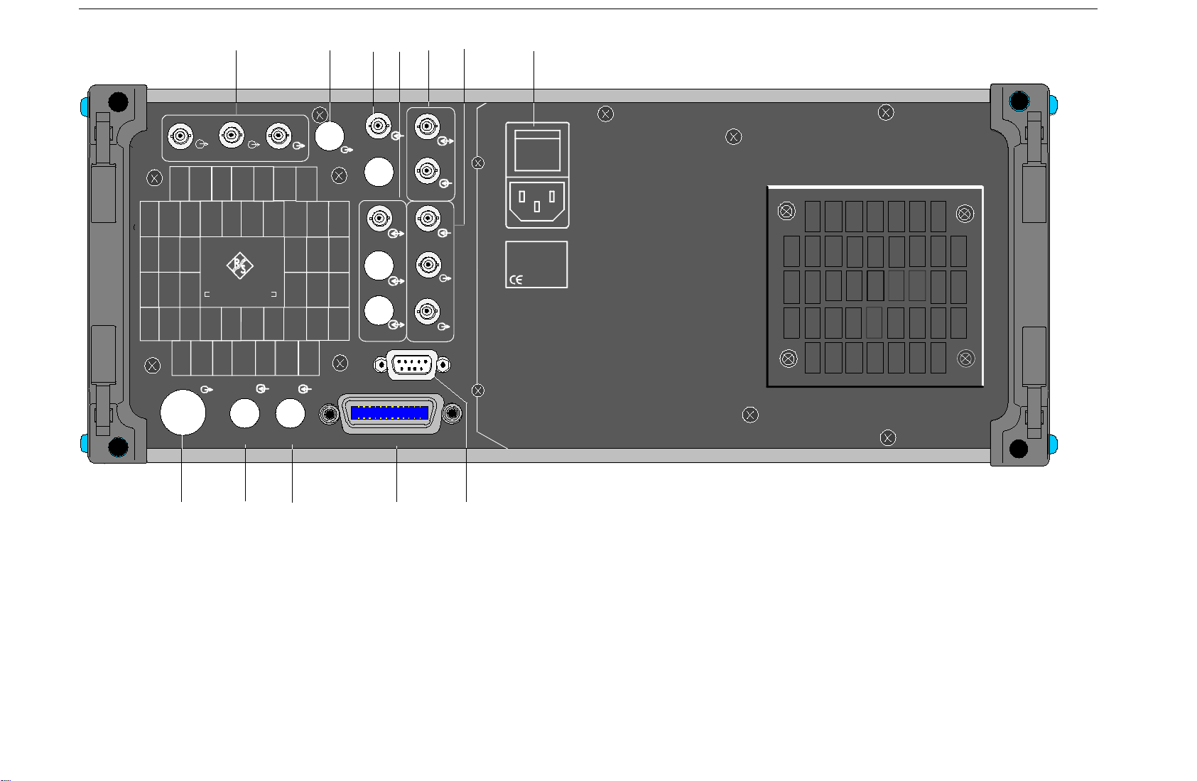
Rear Panel SME
10 12
X-AXIS
MARKER BLANK
RF EXT1 EXT2
11
LF
13
TRIGGER
BURST
DATA
CLOCK
RS 232
IEC625 IEEE488
14
REF
TUNE
PULSE
SYNC
VIDEO
15
16
I
0
100-240 VAC
2,7-1,1 A
50-400 Hz
21 20 19 18
17
Fig. 2-2 Rear panel view
1038.6002.02 2.16 E-13

SME Rear Panel
18
IEC625 IEEE488
19
20
21
EXT 2
EXT1
IEC 625 IEC-Bus (IEEE 488)
IEEE 488 Remote-control interface
EXT2 Cut-out, provided to relocate the EXT2
input at the front to the rear of the
instrument.
EXT1 Cut-out, provided to relocate the EXT1
input at the front to the rear of the
instrument.
RF Cut-out, provided to relocate the RF output
at the front to the rear of the instrument.
See as well
Chapter 3,
Remote Control
RF
1038.6002.02 2.17 E-13

Display SME
2.2 Operating Concept
2.2.1 Display
1
2
3
FREQ
FM
FREQUENCY
LEVEL
MODULATION
DIGITAL MOD
LF OUTPUT
SWEEP
LIST
MEM SEQ
UTILITIES
HELP
Main me nu
100. 000 000 0
Submenu
1 Header field
2 Status line
3 Menu fields
Fig. 2-3 Design of the display
Header field
(1)The header field of the dis play indicates frequency and level of the RF output signal. In
the RF-sweep operating mode, the start and stop frequencies are displayed in two
lines one above the other. The start and stop levels ar e indicated in the LEVEL-sweep
operating mode correspondingly.
AM
FM
PM
PULSE
FM1 DEVIATION
FM1 SOURCE
LFGEN1 FREQ
FM2 DEVIATION
FM2 SOURCE
LFGEN2 FREQ
LFGEN2 SHAPE
EXT1 COUPLING
EXT2 COUPLING
Setting menu
MHz
LEVEL
OFF LFGEN1 EXT1 EXT2
0.4k 1k 3k 15k Hz
2.000 0 kHz
OFF LFGEN2 EXT1 EXT2
27.500 0 kHz
SIN SQR TRI NOI
AC DC
AC DC
- 30.0
dBm
1.00 kHz
Men u c u rs or
Digit cursor
Select mark
Status line
(2)The status line below describes operating m ode and operating state of the ins trum ent.
Error messages and notes for caution are also displayed in the status line.
Menu fields
(3)The indication fields below the header field are reserved for the m enu representations.
The image contents of these fields change as a func tion of the menu selected. The
field at the left-hand display margin is occupied with the main menu, the topm ost level
of the menu structure. The main menu is always faded in.
Each further field adjacent at the right contains submenus.
The field ending with the right-hand display margin shows the setting menu. In this
menu all setting values and setting states connected with the menu selected are
indicated. When access ing submenus, the higher-order menus rem ain in the display.
The current menu path is evident through the select marks.
Menu cursor The menu cursor shows the user at which position in the menu he is.
The position of the menu c ursor is evident fr om the inver se notation of
the term (white characters on a black background)
Digit cursor As an underscore, the digit cursor marks the position which can be
varied by means of the rotary knob in a value indication.
Select mark The frame around a term marks current m enus or valid settings in the
setting menu.
1038.6002.02 2.18 E-13

SME Display
2.2.2 Basic Operating Steps
The operating principle is explained in this section. For better understanding, please read sections
"Display" (Section 2.2.1) and "Sample Setting for First Users" (Section 2.2.3) in addition.
To operate the instrument, menus are called in the display. All setting possibilities and the current
setting status are evident from the menus. All settings can be made by accessing the menus.
RF frequency and RF level can also be set without m enu operation using keys [FREQ] and [LEVEL].
RF signal and modulation can also be switched on/off without menu operation us ing keys [RF ON/OFF]
and/or [MOD ON/OFF].
2.2.3.1 Calling the Menus
Accessing the menus is effected using rotary knob [VARIATION], [SELECT] key and [RETURN] key.
Rotary knob
Rotary knob [VARIATION] moves the menu cursor over the positions of a menu level
to be selected.
If a scrollbar is visible at the left-hand mar gin of a m enu, the menu is larger than the
screen window. If the menu cursor is moved to the m argin of the scr een window, the
covered lines become visible.
[SELECT] key
[RETURN] key
The [SELECT acknowledges the selection marked by means of the menu cursor.
The [RETURN] key
- returns the menu cursor to the next higher menu level.
The menu cursor is shifted to the left into the preceding column of the menu
structure.
- resets the menu cursor from frequenc y or level value indication in the header field
into the menu field to the menu called last.
- closes the display pages called using keys [STATUS], [HELP] and [ERROR]
again.
Settings are accessed in the setting menus ending with the right-hand display margin.
FREQ
AM
100. 000 000 0
MHz
LEVEL
- 30.0
dBm
FREQUENCY
LEVEL
MODULATION
DIGITAL MOD
LF OUTPUT
SWEEP
LIST
MEM SEQ
UTILITIES
HELP
AM
FM
PM
PULSE
AM DE PT H
AM SOURCE INT
AM SOURCE EXT
AM EXT COUPLING
AM POLARITY
LFGEN1 FREQ
LFGEN2 FREQ
LFGEN2 SHAPE
100. 0 %
OFF LFGEN1 LFGEN2
OFF EXT1
AC DC
NORM INV
0.4k 1k 3k 15k Hz
27.500 0 kHz
SI N SQ R T RI NOI
Fig. 2-4 MODULATION-AM menu
1038.6002.02 2.19 E-13

Basic Operating Steps SME
2.2.3.2 Selection and Change of Parameters
Select parameter À Set the menu cursor to the name of the parameter desired using the rotary
knob, e.g. to AM DEPTH in the AM menu, Fig. 2.4..
Change setting
value
via value inputs
using rotary knob
À Via value input or using rotary knob.
À Press the first digit of the new value or minus sign.
The old value is deleted, the entry is indicated in the marked field.
À Enter further digits.
À Terminate the input using a unit key or, in the case of inputs in the base unit
or in the case of inputs without unit, using the [1x/Enter] key.
The menu cursor wraps back to the appropriate parameter.
À Press the [SELECT] key.
À The menu cursor changes from the parameter selected in the left-hand
column of the setting menu to the setting value on the right, e.g. from AM
DEPTH to 30%, Fig. 2-4.
À Set the underscore to the position of the setting value to be varied using
keys [Ø] [×].
À Turn the rotary knob.
The position underscored is varied in steps of 1.
Note: RF frequency and RF level can also be varied in a step width which
can be defined arbitrarily using the rotary knob. In the respective
setting menu (FREQUENCY or LEVEL) the step width is entered as
KNOB STEP USER and the KNOB STEP set from DECIMAL to
USER. To point to the fact that the step width has been converted to
the value programmed, the underscore as a symbol of the digit
cursor disappears in the respective value indication.
1-out-of-n selection À Select parameters.
À Press the [SELECT] key.
The menu cursor changes from the parameter selected in the left-hand
column of the setting menu to the current selection on the right, e.g. from
LFGEN1 FREQ to 0.4 kHz, Fig. 2-4.
À Set the menu cursor to the position desired within the 1-out-of-n selection
using the rotary knob or cursor keys [⇐] [⇒].
À Press the [SELECT] key.
The setting is made.
The selection mark which has marked the setting valid up to now wraps to
the new position.
À Press the [RETURN] key.
The menu cursor wraps back to the respective parameter
1038.6002.02 2.20 E-13

SME Basic Operating Steps
Quick selection of
a parameter
The quick selection of a parameter reduces the number of operating steps if
several parameters are set successively. The menu cursor can directly be set
further from line to line in the column of the setting values by pressing the
[SELECT] key.
The menu cursor wraps from the setting value of a parameter to the setting
value of the parameter in the next line.
The column of the setting values can be exited at each position by pressing
the [RETURN] key.
2.2.3.3 Triggering Action
Lines in the setting menu which are m arked with the "Ð" symbol at the end of the line qualif y an action
which can be carried out. Instruction SEARCH ONCE Ð in the LEVEL-ALC menu, e.g., switches on
level control for level calibration for a short period of time.
Trigger action À Set the menu cursor to the respective instruction.
À Press the [SELECT] key.
The action is triggered.
While the action is carried out, the instruction remains framed by the
selection mark.
2.2.3.4 Quick Selection of Menu (QUICK SELECT)
The keys of the QUICK SELECT control field are used to call selected menus quickly by one keystroke.
Store menus À Establish the desired operating status of the current menu.
À Press the [ASSIGN] key.
À Press key [MENU1] or [MENU2].
The current menu is stored as menu1 or menu2. That is to say, 2 menus
can be stored in total.
Call menus À Press key [MENU1] or [MENU2].
Menu1 or menu2 stored is displayed. Exactly the operating status which was
current at the point of time of storing is reconstructed.
1038.6002.02 2.21 E-13

Basic Operating Steps SME
2.2.3.5 Use of [FREQ] and [LEVEL] Keys
RF frequency and RF level can be set without menu operation as well using dir ect keys [FREQ] and
[LEVEL]. The input value considers the offset, see Sections 2.4 and 2.5.
Key [FREQ]/ [LEVEL] À Press the [FREQ] or [LEVEL] key.
The frequency and/or the level indication in the header field of the display
is marked.
The current menu at the display is maintained.
À Alter the value via a value input or the rotary knob.
À Press the [RETURN] key.
The menu cursor wraps to the position marked last in the menu.
2.2.3.6 Use of [RF ON / OFF] and [MOD ON / OFF] Keys
RF signal and modulation can be switched on/off without menu operation as well using direct keys
[RF ON / OFF] and/or [MOD ON / OFF] (see Section 2.6.1.3, [MOD ON/OFF] key as well).
Key [RF ON / OFF] À Press the [RF ON / OFF] key.
The RF output signal is switched on/off.
IEC-bus command: :OUTP:STAT ON
Key [MOD ON / OFF] À Press the [MOD ON / OFF] key.
The modulation is switched on/off.
A direct IEC-bus command is not available. The modulations have to be
switched on and off in the respective modulation submenus.
2.2.3.7 Changing Unit of Level
For the level, the unit of the value set can be changed without a new value input.
Change level unit À Activate LEVEL parameter.
- Press the [LEVEL] key or
- set the menu cursor in the LEVEL menu to the setting value of the
AMPLITUDE parameter.
À Press the unit key with the desired level unit.
The level is indicated in the desired unit.
1038.6002.02 2.22 E-13

SME Sample Setting for First Users
2.2.3.8 Correction of Input
Digital entries can be corrected by one of the unit/Enter keys before terminating the input.
Key [-/
Ï
]
The backspace key deletes the value entered digit by digit. When the last
digit is deleted, the previous value is displayed.
Key [RETURN]
Pressing the [RETURN] key deletes the entire entry and results in the
previous value being indicated again.
For a subsequent new input in the setting menu, the first digit of the new
value is to be entered.
For a subsequent new input via the [FREQ] or [LEVEL] keys, the respective
key has to be pressed again.
Key [FREQ]/ [LEVEL]
In the case of a frequency or level input by means of the [FREQ] or [LEVEL]
keys, pressing the [FREQ] and/or [LEVEL] key again deletes the entire input.
2.2.4 Sample Setting for First Users
First users mos t quickly becom e fam iliar with the operation of the instrum ent if they execute the pattern
setting of this section.
First frequency and level of the RF output signal are set via keys [FREQ] and [LEVEL] in the DAT A
INPUT field:
- Frequency 250 MHz
- Level 10 dBm
Operating steps Explanations
PRESET
DATA INPUT
FREQ
LEVEL
RETURN
2
1
5
DATA INPUT
0
Reset the instrument to the defined
state.
Set the frequency to 250 MHz. The
0
M
dBµV
µ
menu cursor marks the permanent
frequency indication.
Set the level to 10 dBm. The menu
x1
ENTER
cursor marks the permanent level
indication.
Reset the menu cursor to the menu
field.
1038.6002.02 2.23 E-13

Sample Setting for First Users SME
The output signal is to be amplitude-modulated next.
- AM modulation depth 15.5 %
- AM signal 3-kHz sine
Operating steps Explanations
MENU / VARIATION
MENU / VARIATION
ME NU / VAR I A T I O N
.
MODULATION
.
.
AM
.
.
AM DEPTH
.
MENU / VARIATION
SELECT
MENU / VARIATION
SELECT
Select MODULATION menu.
À Set menu cursor to MODULATION
using the rotary knob and
subsequently press
[
SELECT] key.
The submenu is displayed
Select AM submenu
The AM setting menu is displayed.
Select AM DEPTH parameter.
The menu cursor marks the setting
value.
Enter modulation depth 15.5 % and
acknowledge.
The menu cursor is reset to AM
DEPTH.
Select AM SOURCE INT.
N
MENU
/ V
ARIATIO
1
DATA INPUT
.
5
N
0
x1
ENT E R
MENU
/ V
ARIATIO
The menu cursor marks the current
.
AM SOURCE INT
SELECT
1-out-of-n selection.
.
1038.6002.02 2.24 E-13

SME List Editor
Operating steps Explanations
/ V
MENU
ARIATI
SELECT
ON
Select LF generator 1 as modulation
source.
The selection mark marks LFGEN1.
AM is faded in the status line as a
hint that AM is switched on.
MENU
/ V
ARIATI
ON
.
LFGEN1
.
RETURN
MENU / VARIATION
.
LFGEN1 FREQ
.
DATA INPUT
3
k
m
The AM modulation setting is completed.
Reset menu cursor to AM SOURCE
INT.
Select parameter LFGEN1 FREQ.
The menu cursor marks the current
frequency selection.
Set the frequency of LF generator 1
to 3 kHz.
The selection mark marks 3 kHz.
The indications on the display are
represented in Fig. 2-5.
FREQ
AM
FREQUENCY
LEVEL
MODULATION
DIGITAL MOD
LF OUTPUT
SWEEP
LIST
MEM SEQ
UTILITIES
HELP
250. 000 000 0
AM
FM
PM
PULSE
AM DEPTH
AM SOURCE INT
AM SOURCE EXT
AM EXT COUPLING
AM POLARITY
LFGEN1 FREQ
LFGEN2 FREQ
LFGEN2 SHAPE
MHz
LEVEL
15.5 %
OFF LFGEN1 LFGEN2
OFF EXT1
AC DC
NORM INV
0.4k 1k 3k 15k Hz
1.000 0 kHz
SIN SQR TRI NOI
- 10 .0
dBm
Fig. 2-5 Display after AM setting
1038.6002.02 E-13
2.25

List Editor SME
Subsequently to the above setting, 420 MHz as new RF frequency and 12.5 kHz as the step width for
the RF frequency variation are set in the following. Parameter quick select is used, which r educes the
number of operating steps.
Operating steps Explanations
RETURN
MENU / VARIATION
MENU / VA RIA T ION
DATA INPUT
4
2
RETURN
.
FREQUENCY
.
.
FREQUENCY
.
0
MENU / VARIATION
M
µ
SELEC T
Reset the menu cursor to the main
menu in 2 steps.
Select FREQUENCY menu.
The frequency setting menu is
displayed.
Select FREQUENCY parameter.
The menu cursor marks the setting
value.
Enter frequency 420 MHz and
acknowledge.
MENU / V ARIATION
Set menu cursor to the setting value
of parameter KNOB STEP USER.
.
KNOB STEP USER
.
DATA INPUT
1
ME NU / VAR IA T ION
.
2
5
k
m
Enter step width 12.5 kHz.
Set menu cursor to param eter KNOB
STEP
.
KNOB STE P
.
1038.6002.02 E-13
2.26

SME List Editor
Operating steps Explanations
MENU / VARIATION
RETURN
USER
.
RETURN
MENU / VARIATION
Select USER (user-defined step
width).
.
SELEC T
The selection mark marks USER.
This results in step width 12.5 kHz
being used in the case of variation
using the rotary knob.
Reset the menu cursor to the main
menu in 2 steps.
FREQ
AM
FREQUENCY
LEVEL
MODULATION
DIGI TA L M O D
LF OUTPUT
SWEEP
LIST
MEM SEQ
UTIL ITIE S
HELP
420. 00 0 000 0
FREQUENCY
OFFSET
KNOB STEP USER
KNOB STEP
EXCLUDE FROM RCL
MHz
LEVEL
420.000 000.0 MHz
0.0 Hz
12.500 0 kHz
DECIMAL USER
1 0.0
ON OFF
dBm
Fig. 2-6 Display after pattern setting
1038.6002.02 E-13
2.27

List Editor SME
2.2.4 List Editor
The SME offers the possibility to generate lists. Lists are used for setting sequences (LIST m ode or
memory sequence), as data s ource for digital m odulations or for level correc tion which can be defined
by the user (UCOR). They consist of elements which are defined by an index and at least one
parameter per index. Each list is marked by a separate name and c an be selected via this name. T he
lists are accessed in the menus ass igned in each case, e.g. to the s ettings sequenc es of fr equency and
level value pairs in the LIST menu. However, the lists are always generated and processed in the same
way and the procedures are hence explained in detail by the example of the mem ory sequence mode
(menu MEM SEQ) in this sec tion. A pattern setting at the end of this section allows the us er to bec ome
familiar with the operation of the list editor.
Setting menus providing list processing are structured in two pages:
The first page, called OPERAT ION page in the following contains the general conf iguration param eters
for processing a list. Further , the general list functions s uch as selecting and deleting the list as well as
calling an editing mode are provided. The second page, the EDIT page, is autom atically displayed when
calling an edit function and serves to enter and modify the parameters of the list.
The OPERATION page has a sim ilar arrangem ent with all list editors. As an exam ple, the OPERAT ION
page of the MEM SEQ menu is shown:
Menu selection: MEM SEQ
FREQ
FREQUENCY
LEVEL
MODULATION
DIGITAL MOD
LF OUTPUT
SWEEP
LIST
MEM SEQ
UTILITIES
HELP
100. 00 0 0 00 0
OFF AUTO SINGLE STEP EXT-SINGLE EXT-STEP
MODE
RES ET SEQUENCE
CURRENT INDEX 1
SELECT LIST... CURRENT: MSEQ2
DELETE LIST...
FUNCTION FILL INSERT DELETE EDIT/VIEW
MHz
LEVEL
- 30.0
dBm
Fig. 2-7 OPERATION page of the MEM SEQ menu
The settings for MODE, CURRENT INDEX, etc. are irrelevant for the general description of the list
editors and are described in greater detail in Section 2.10, MEMORY SEQUENCE mode.
The last three menu lines of the OPERATION page always exist and are reserved for selecting and
deleting lists as well as for calling the edit functions (and hence the EDIT page)
SELECT LIST
Opens a selection window in which a list can be selected from the existing lis ts or a
new, empty list can be generated. In this line the active list is always displayed.
DELETE LIST
1038.6002.02 E-13
Opens a selection window in which the list to be deleted can be selected..
2.28

SME List Editor
FUNCTION
Selection of the edit function for processing the lists. The EDIT page is
automatically called through the selection (cf. Section 2.2.4.3).
FILL Filling a list with elements.
INSERT Insertion of elements into a list.
DELETE Deletion of elements of a list.
2.2.4.1 Select and Generate - SELECT LIST
SELECT LIST opens a selection window in which either an existing list can be selected or a new, empty
list can be generated (cf. Fig. 2-8). By pressing the [RETURN] key, the selection window is closed
without changing the setting.
Select list
Generate list
À Mark the list desired using the rotary knob.
À Press [SELECT] key.
The selected list is included in the instrument setting. The selection window
is closed. The selected list is displayed under CURRENT.
À Mark CREATE NEW LIST ➤ using rotary knob.
À Press [SELECT] key.
A new empty list is automatically generated which can be filled using
functions FILL or EDIT. The selection window is closed. The new list is
displayed under CURRENT.
No modification
À Press [RETURN] key.
of the setting
Selection: DELETE
FREQ
FREQUENCY
LEVEL
MODULATION
DIGI TA L M O D
LF OUTPUT
SWEEP
LIST
MEM SEQ
UTIL ITIE S
HELP
100. 000 000 0
MODE OFF AUTO SINGLE
EXECUTE SINGLE MODE
RESET
CURRENT INDEX
SELECT LIST...
DELETE LIST...
FUNCTION
Fig. 2-8 SELECT-LIST-selection window
MHz
LEVEL
CREATE NEW LIST
MSEQ1 199
MSEQ2 100
MSEQ3 1
MSEQ4 123
- 30.0
dBm
1038.6002.02 E-13
2.29

List Editor SME
CREATE NEW LIST Ð
Generating a new list. The name of the list cannot be selected freely in the
case of manual control. A definite list nam e is automatically generated in the
following fo rm:
MSEQ<n>, with <n> ∈ {0..9}, e.g. MSEQ1 (with Memory Sequence)
This applies correspondingly to the other operating modes. In the case of
LIST mode, LIST1 would be generated for example. If a list is created via IEC
bus, an arbitrary list name can be given (cf. Section 3). Unrestricted access is
also possible by means of the selection window.
MSEQ2 100
The list currently set is marked in the selection window by means of the
selection mark, here SEQ2. In addition to the list name, the length of the list
is given, here 100 elements.
2.2.4.2 Deletion of Lists - DELETE LIST
DELETE LIST opens a selection window in which the list to be deleted can be selec ted.. The lists are
represented together with their name and their length (cf. Fig. 2-9). By pressing the [RET URN] key the
selection window is exited without deleting a list.
Delete list
À Mark desired list using the rotary knob.
À Press [SELECT] key.
The prompt "enter [SELECT to delete list/sequence?" is displayed
Selection: DELETE LIST
FREQ
FREQUENCY
LEVEL
MODULATION
DIGI TA L M O D
LF OUTPUT
SWEEP
LIST
MEM SEQ
UTIL ITIE S
HELP
100. 000 000 0
ÀPress [SELECT] key.
The list is deleted. If the prompt is acknowledged with the [RETURN] key,
however, the list is not deleted. The selection window is automatically
closed due to the acknowledgment of the prompt.
MHz
MODE OFF AUTO SINGLE
RESET SEQUENCE
CURRENT INDEX
SELECT LIST...
DELETE LIST...
FUNCTION
LEVEL
MSEQ1 199
MSEQ2 100
MSEQ3 1
MSEQ4 123
- 30.0
dBm
Fig. 2-9 DELETE-LIST selection window
1038.6002.02 E-13
2.30

SME List Editor
2.2.4.3 Edition of Lists
Due to the selection of an edit mode on the OPERATION page the EDIT page is automatically activated.
When the EDIT /VIEW function is selected, the largest possible section of the list is dis played (cf. Fig.
2-10). In the case of block functions FILL, INSERT and DELETE, an input window is additionally
displayed (cf. Fig. 2-11 to 2-13).
Functions SELECT LIST and FUNCTION are available on the EDIT page as on the OPERATION page.
Return to the OPERATION page is effected by pressing the [SELECT] key twice.
Single-value function EDIT/VIEW
By selecting the EDIT/VIEW function, the entire list can be viewed or m odifications of single values be
carried out.
If the cursor marks a value in the INDEX column of the list, the EDIT m ode is exited by pressing the
[RETURN] key. The menu cursor then marks FUNCTION again.
There is no separate function for storing the list. This means that every modification of the list is
transferred to the internal data set and has an effect on exiting the EDIT/VIEW function.
Selection: FUNCTION EDIT/VIEW
FREQ
FREQUENCY
LEVEL
MODULATION
DIGITAL MOD
LF OUTPUT
SWEEP
LIST
MEM SEQ
UTILITIES
HELP
100. 000 000 0
SELECT LIST... CURRENT: MSEQ2
FUNCTION
-INDEX - FREE 2041 - LEN 2055 MEMORY DWELL
09 50 ms
0001
0002 02 50 ms
0003 01 60 ms
0004 23 60 ms
0005 09 85 ms
0006 10 85 ms
0007 08 85 ms
0008 11 85 ms
Fig. 2-10 Edit function EDIT/VIEW
INDEX
FREE
Position in the list
Space available. FREE 2041 means that space f or 2041 parameter elem ents
is available in the list memory in total.
LEN
Occupied space. LEN 2055 means that the current list occupies 2055
elements in the list memory.
MHz
LEVEL
INSERTFILL EDIT/VIEW
-30.0
DELETE
dBm
MEMORY DWELL
Identification of the column below. The number of parameter columns is
different for the various list editors. The list editor for digital modulation data
possess three parameter columns (DATA, BURST and LEVEL
ATTENUATION).
1038.6002.02 2.31 E-13

List Editor SME
Select parameters
Modify parameters
Block function FILL
À Mark the index associated to the parameter using the rotary knob or directly
enter the value of the index via the numeric keys.
À Press [SELECT] key.
Parameter MEMORY is marked. If the second parameter DWELL is to be
marked, press the [SELECT] key again.
À Vary the value of the parameter selected using the rotary knob or enter the
value directly using numeric keys.
Note: The binary coder data of the digital modulations which cannot be
varied are an exception. Further, all numeric k eys except for "0" and
"1" are ineffective in these cases.
À Press the [ENTER] key or unit keys.
The value is included in the data set. The menu cursor marks the value of
the next column. In the last column, the menu cursor then marks the next
line of column MEMORY.
À Press the [RETURN] key.
The menu cursor wraps back to the INDEX column. The EDIT mode is
exited by repeatedly pressing the [RETURN] key (cf. Section 2.2.4.4).
Using function FILL, a parameter, e.g. MEMORY, is overwritten with constant or linearly
increasing/decreasing values within a defined range. The input window is exited by pressing the
[RETURN] key without a modification being carried out.
If the filler range exceeds the end of the list, the list is automatically extended.
The list entry, in the example for MEMORY, with index [AT +n] is calculated as follows from the
information AT, RANGE, starting value (MEMORY) and WITH INCREMENT:
MEMORY[AT+n] = starting value (MEMORY)+ n · increment | (0 ≤ n ≤ RANGE1)
Selection: FUNCTION-FILL
FREQ
FREQUENCY
LEVEL
MODULATIO N
DIGITAL M OD
LF OUTPUT
SWEEP
LIST
MEM SEQ
UTILITIES
HELP
100. 00 0 000 0
SELECT LIST...
FUNCTION
-IND EX - FREE 2041 - LEN 2055
0001
0002
0003
0004
0005
0006
0007
0008
MHz
FILL AT
PARAMETER MEMORY DWELL
MEMORY 1
WITH INCREMENT 0
EXECUTE
LEVEL
10 RANGE 1
- 30.0
dBm
Fig. 2-11 Block function FILL: Input window
1038.6002.02 2.32 E-13

SME List Editor
FILL AT
PARAMETER
MEMORY
OR DWELL
WITH INCREMENT
Setting the filling range.
AT Lower limit (index)
RANGE Number of the elements to be inserted
Selection on which of the parameters the filling function is to have an effect.
This menu option is eliminated if the list only includes elements with one
parameter.
Input of the starting value for the parameter selected. This option is only
displayed if a selection has been made under PARAMETER MEMORY or
DWELL.
Input of the increment between two successive values. If 0 is entered as
increment, a filling procedure with constant values is ac hieved. This option is
only displayed if a selection has been made under PARAMETER MEMORY or
DWELL.
Note: In the case of some ty pes of lists , e.g. digital modulation data, indic ating
an increment is eliminated since there are binary data. In these cases
line WITH INCREMENT is eliminated.
EXECUTE Ð
Filling a list After selection of function FILL, the menu cursor marks FILL AT.
Starts the filling sequence. After the function has been executed, the input
window is automatically exited. The current index points to the first element
after the processed range.
À Press the [SELECT] key.
The menu cursor marks the value at AT.
À Vary index value using the rotary knob or enter using the numeric keys and
the [ENTER] key.
À Press the [SELECT] key.
The menu cursor marks the value at RANGE.
À Vary value using the rotary knob or enter using the numeric keys and the
[ENTER] key.
À Press the [SELECT] key.
The menu cursor marks MEMORY or DWELL in input line PARAMETER.
À Select MEMORY using the rotary knob (if not yet marked) and press the
[SELECT] key.
The menu cursor marks the value in input line MEMORY.
À Vary starting value for column MEMORY using the rotary knob or enter
using the numeric keys and the [ENTER] key.
À Press the [SELECT] key
The menu cursor marks the value in input line WITH INCREMENT.
À Vary the value of the increment desired using the rotary knob or enter using
the numeric keys and the [ENTER] key.
À Press the [RETURN] key.
À Mark the action EXECUTE Ð
À Press the [SELECT] key.
The filling sequence is initiated. After the function has been carried out, the
input window is automatically exited. The menu cursor marks FUNCTION.
The EDIT page shows the end of the range that has been filled right now.
1038.6002.02 2.33 E-13

List Editor SME
Block function INSERT
Function INSERT inserts the desired number of elements with constant or linearly
increasing/de-creasing values before the elem ent with the given starting index. All elements which had
been stored from the starting index are shifted to the end of the range to be inserted.
Input is effected analogously to filling a list.
By pressing the [RETURN] key the input window is exited without a modification being effect ed. The
menu cursor then marks FUNCTION.
The list entry, in the example for MEMORY, with index [AT +n] is calculated as follows from the
information AT, RANGE, starting value (MEMORY) and WITH INCREMENT:
MEMORY[AT+n] = starting value (MEMORY) + n · Increment | (0≤n≤RANGE-1)
Selection: FUNCTION INSERT
FREQ
FREQUENCY
LEVEL
MODULATION
DIGITAL MOD
LF OUTPUT
SWEEP
LIST
MEM SEQ
UTILITIES
HELP
100. 000 000 0
SELECT LIST...
FUNCTION
-INDEX - FREE 2041 - LEN 2055
0001
0002
0003
0004
0005
0006
0007
0008
Fig. 2-12 Edit function INSERT: Input window
INSERT AT
Input of the starting index and the number of the elements to be inserted.
AT Starting index before which the insert operation is to be effective.
RANGE Number of the elements to be inserted
MEMORY
DWELL
Input of the starting value for MEMORY.
Input of the starting value for DWELL.
MHz
LEVEL
INSERT AT
MEMORY 1
WITH INCREMENT 0
DWELL 100ms
WITH INCREMENT 0.0ms
EXECUTE
10 RANGE 2
- 30.0
dBm
WITH INCREMENT
Input of the increment between two successive values for MEMORY or
DWELL. If 0 is indicated as increment, constant values are achieved to be
inserted RANGE times.
Note: In the case of some ty pes of lists , e.g. digital modulation data, indic ating
an increment is eliminated since there are binary data. In these cases
all lines WITH INCREMENT are eliminated.
EXECUTE Ð
Starts the inserting sequence. After the f unction has been executed, the input
window is automatically exited. The menu cursor mark s FUNCT IO N. T he EDIT
page shows the beginning of the range that has moved forward.
1038.6002.02 2.34 E-13

SME List Editor
Block function DELETE
Function DELETE deletes the elements of the range indic ated. This does not leave a gap in the list but
the remaining elements move forward. If the given range ex ceeds the end of the list, deletion until the
end of the list is effected.
Input is analog to filling a list.
By pressing the [RETURN] key, the input window is exited without a modification being carried out. The
menu cursor then marks FUNCTION.
Selection: FUNCTION DELETE
FREQ
FREQUENCY
LEVEL
MODULATION
DIGITAL MOD
LF OUTPUT
SWEEP
LIST
MEM SEQ
UTILITIES
HELP
100. 000 000 0
SELECT LIST...
FUNCTION
-INDEX - FR EE 2041 - LEN 205 5
0001
0002
0003
0004
0005
0006
0007
0008
Fig. 2-13 Edit function DELETE: Input window
DELETE AT
Input of the block of the list to be deleted
AT Lower limit (INDEX)
RANGE Number of elements to be deleted.
EXECUTE Ð
Starts the deletion. After the function has been executed, the input window is
automatically exited. The menu cursor marks FUNCTION. The EDIT page
shows the beginning of the range that has moved forward.
MHz
DELETE AT
EXECUTE
LEVEL
10 RANGE 2
- 30.0
dBm
2.2.4.4 Pattern Setting to Operate the List Editor
The user can become familiar with the operation of the list editor by means of the following pattern
setting in the MEM SEQ menu. A list has to be generated and filled with values by using the
single-value function EDIT/VIEW:
• Memory location number of the first element 20
• Dwell time of the first element 15s
• Memory location number of the second element 1.
When the setting has been terminated, return to the OPERATION page of the MEM SEQ menu.
1038.6002.02 2.35 E-13

List Editor SME
At the beginning of the operation sequence, menu MEM SEQ is called. First a lis t MSEQ0 has to be
generated and then activated. The menu cursor marks a parameter of the setting menu on the
OPERATION page (c.f. Fig. 2-14).
FREQ
FREQUENCY
LEVEL
MODULATION
DIGI TA L M O D
LF OUTPUT
SWEEP
LIST
MEM SEQ
UTIL ITIE S
HELP
100. 000 000 0
MODE
OFF AUTO SI NGLE STEP EXT-SINGLE EXT-STEP
RESE T SEQU EN CE
CURRENT INDEX 1
SELECT LIST... CURRENT: MSEQ2
DELETE LIST...
FUNCTION FILL INSERT DELETE EDIT/VIEW
Fig. 2-14 Starting point of the pattern setting
Operating steps Explanations
MHz
LEVEL
- 30.0
dBm
MENU / VARIATION
MENU / VARIATION
MENU / VARIATION
.
SELECT LIST...
.
CREATE NEW LIST
.
FUNCTION
.
MENU / VARIATION
SELECT
MENU / VARIATION
SELECT
MENU / VARIATION
SELEC T
Select the SELECT LIST menu item.
A new list MSEQ0 is generated. The
menu cursor is reset to SELECT
LIST...
Select the FUNCTION menu item.
1038.6002.02 2.36 E-13

SME List Editor
MENU / VARIATION
SELECT
.
DATA INPUT
0
2
DATA INPUT
5
1
EDIT/VIEW
MENU / VARIATION
.
1x
ENTER
1x
ENTER
SELEC T
Select single-value function
EDIT/VIEW.
The EDIT page of the MEM SEQ
menu is called. The menu cursor
marks the index of the first element
of list MSEQ0.
Set the menu cursor to the memory
location number value of the first
element (c.f. Fig. 2-15,A).
Enter MEMORY 20.
The menu cursor automatically wraps
to the DWELL value of the first
element (Fig. 2-15,B). The default
value is 100 ms.
Enter DWELL 15 s.
The menu cursor automatically wraps
to the MEMORY value of the second
element.
DATA INPUT
1
1x
ENTER
Enter MEMORY 1.
The menu cursor automatically wraps
to the DWELL value of the second
element (default value is 100 ms).
Reset the menu cursor to the index.
RETURN
Reset the menu cursor to the
RETURN
FUNCTION menu item of the EDIT
page of menu MEM SEQ (c.f. Fig. 215,C).
Reset the menu cursor to the
RETURN
FUNCTION menu item of the
OPERATION page of menu MEM
SEQ.
Note: With the return to the OPERATION page the operation of the list editor is finished. In the list
mode (menu LIST), function LEARN
➤
must be activated subsequently to ensure that the
settings are transferred to the hardware.
1038.6002.02 2.37 E-13

List Editor SME
Fig. 2-15, a to c Pattern setting - Edition of a list
1038.6002.02 2.38 E-13

SME Save/Recall
2.2.5 Save/Recall - Storing/Calling of Instrument Settings
50 complete instrument settings can be stored in memory locations 1 to 50.
Operating steps Explanations
Store current instrument setting in
memory location 12.
Call instrument setting of memory
location 12.
SAV
RCL
DATA INPUT
E
21
1x
ENTER
DATA INPUT
21
1x
ENTER
The digital display during a save or recall entry is faded in a window.
Memory location 0 has a special function. Here the instrument setting which was current prior to the las t
memory recall and prior to a preset setting is automatically stored. This permits the resetting of
instrument settings which have inadvertently been deleted using Recall 0.
If an instrument setting is stored in which a sweep was switched on, the sweep is started using the
recall.
The parameter EXCLUDE FROM RCL in the FREQUENCY and LEVEL-LEVEL menus determines
whether the saved RF frequency and RF level are loaded when an instrument setting is loaded, or
whether the current settings are maintained.
Store IEC-bus command: "*SAV 12"
Call IEC-bus command: "*RCL 12"
Notes: – The contents of lists, as they are used for the LIST mode or for user cor rection (UCOR), is
not saved in the SAVE memory. It is stored under the respective list name and can be
called. If instrument settings are called which go back to list data such as level setting using
UCOR, the current list contents is us ed. If this has been alter ed, it is not identical to the list
contents at the point of storing any more.
–
Memory Sequence is dealt with in Section 2.10.
- Model SME03A and units that are equipped with option SM-B50, comprise the "Fast Restore"
mode for very fast loading of stored device settings. This mode can be called up only
during remote control (see section 3, "Fast Restore Mode".)
1038.6002.02 2.39 E-13

Menu Summary SME
2.3 Menu Summary
FREQUENCY
LEVEL
MODULATION
DIGITAL MOD
LF OUTPUT
LEVEL
ALC
UCOR
EMF
AM
FM
PM
PULSE
STEREO
VOR
ILS-GS
ILS-LOC
MKR-BCN
GMSK
GSFK
QPSK
GSK
4FSK
FFSK
ERMES
FLEX
POCSAG
REFLEX
(Option SM-B5)
(Option SM-B5)
(Option SM-B3/B8/B9)
(Option SM-B5/B6)
(Option SM-B6)
(Option SM-B6)
(Option SM-B6)
(Option SM-B6)
(Option SME-B11 )
(Option SME-B11)
(Option SME-B11)
(Option SME-B11)
(Option SME-B11)
(Option SME-B11)
(Option SME-B11 and SME-B12)
(Option SME-B11, SME-B12 and SME-B41 )
(Option SME-B11, SME-B12 and SME-B42 )
(Option SME-B11, SME-B12 and SME-B43 )
SWEEP
LIST
MEM SEQ
UTILITIES
HELP
FREQ
LEVEL
LFGEN (Option SM-B2/SM-B6)
SYSTEM
REF OSC
PHASE
PROTECT
CALIB
DIAG
TEST
MOD KEY
AUX I/O
BEEPER
GPIB
RS232
SECURI TY
LANGUAGE
CONFIG
TPO INT
PARA M
VCO SUM
LEV PRESE T
PULSE GEN (Option SM-B4)
REF OSC
QPSK (Option SME-B11)
LEVEL
1038.6002.02 2.40 E-13

SME RF Frequency
2.4 RF Frequency
The frequency of the RF output signal can be set dir ectly using the [FREQ] k ey (cf. Section 2.2.2.5) or
by accessing menu FREQUENCY.
In the FREQUENCY menu, the frequency of the RF output signal is indicated under FREQUENCY.
In the case of frequency settings effected in the FREQUENCY menu, the value entered directly is the
frequency of the RF output signal.
The input value of frequency settings opened by means of the [FREQ] key considers the offset in
calculation (cf. next Section). This offers the possibility of entering the desired output frequency of
possibly series-connected instruments such as mixers in the menu.
Note: Further settings: Frequency sweep Menu SWEEP
LF frequency Menu MODULATION
Menu LF-OUTPUT
int./ext. reference frequency Menu UTILITIES-REF OSC
Phase of the output signal Menu UTILITIES-PHASE
Menu selection: FREQUENCY
FREQ
FREQUENCY
LEVEL
MODULATION
DIGITAL MOD
LF OUTPUT
SWEEP
LIST
MEM SEQ
UTILITIES
HELP
100. 000 000 0
FREQUENCY
OFFSET
KNOB STE P USER
KNOB STE P
EXCLUDE F ROM RCL
Fig. 2-16Menu FREQUENCY (preset setting)
FREQUENCY
Input value of the RF frequency considering the OFFSET input value. The
frequency of the RF output signal is determined by input values FREQUENCY
and OFFSET (cf. Section 2.4.1 Frequency Offset).
IEC-bus command SOUR:FREQ 100E6
OFFSET
Input value of the frequency offset, e.g., of a series-connected mixer (cf.
Section 2.4.1, Frequency Offset).
IEC-bus command SOUR:FREQ:OFFS 0
MHz LEVEL
- 30.0
100. 000 000 0 MHz
0.0 Hz
1. 000 000 0 MHz
DECIMAL USER
ON OFF
dBm
KNOB STEP USER
Input value of the step width for frequency variation using the rotary knob. The
RF frequency is varied in the step width entered if KNOB STEP is set to USER.
IEC-bus command SOUR:FREQ:STEP 1MHz
1038.6002.02 2.41 E-13

RF Frequency SME
KNOB STEP
DECIMAL: Variation step width corresponding to the position of the digit
cursor.
USER: "User Defined", variation step width as entered under KNOB
STEP USER .
EXCLUDE FROM RCL
OFF The saved frequency is loaded as well when instrument settings
are loaded with the [RCL] key or with a memory sequence.
IEC-bus command SOUR:FREQ:RCL INCL
ON The RF frequency is not loaded when instrument settings are
loaded, the current frequency settings are maintained.
IEC-bus command SOUR:FREQ:RCL EXCL
2.4.1 Frequency Offset
The SME offers the poss ibility of entering an offset ( OFFSET ) of poss ibly series-connected instr uments
in the FREQUENCY menu. The indication/input value of FREQ in the header field cons iders this input
and represents the frequency value of the RF signal at the output of these instruments (cf. Fig. 2-17).
The entry values FREQUENCY and OFFSET in the menu FREQUENCY or FREQ in the header line are
related to the RF output frequency as follows :
FREQ - OFFSET = output frequency (= FREQUENCY).
An offset entry causes no modification of the RF output frequency but only a modification of the display
value in the FREQ field in the header line, ie FREQ in the header line indicates the offset-associated
frequency and FREQUENCY in the menu FREQUENCY the RF output frequency. The status line
indicates FREQ-OFFST.
The offset setting also remains effective with the frequency sweep.
Input value
OFFSET
(FREQUENCY menu)
L.O.
SME
×
Ø
RF output frequ ency
(FREQUENCY in the FREQUENCY menu)
Mixer
FREQ in the header field
Fig. 2-17 Example of a circuit with frequency offset
1038.6002.02 2.42 E-13

SME RF Level
2.5 RF Level
The RF output level can be set directly using the [LEVEL] key (cf . Section 2.2.2.5) or by accessing the
LEVEL menu.
In the LEVEL-LEVEL menu, the set RF output level is indicated under AMPLITUDE. A two-line level
display appears for digital modulation or digital standar d. The upper line indicates the average power
(LEVEL), the lower line the peak envelope power (PEP) of the modulated RF output signal.
The input value of level settings effected in the LEVEL-LEVEL menu directly corresponds to the RF
output level.
The input value of the level settings opened using the [LEVEL] key mathematic ally considers the offset
of an attenuation/amplification element which is possibly series-connected (cf. Section 2.5.1). This offers
the possibility of entering the desired level at the output of series-connected instruments, the SMIQ then
alters the RF output level correspondingly. The offset can also be entered in the LEVEL-LEVEL menu.
dBm, dBµV, mV and µV can be used as level units. T he 4 unit keys are directly labeled with these units .
In order to change to another level unit, simply press the desired unit key.
Notes: - The mes sage ERROR is displayed in the status line if the level s et in the overrange is
not reached.
- For digital modulation or digital standard, a WARNING message appears in the status
line if the set LEVEL or the displayed PEP are overranged. If the set level cannot be
generated as an overrange value, ERROR will be displayed.
- Further settings: Level sweep menu SWEEP
Menu selection: LEVEL – LEVEL
FREQ
FREQUENCY
LEVEL
MODULATION
DIGITAL MOD
LF OUTPUT
SWEEP
LIST
MEM SEQ
UTILITIES
HELP
100. 000 000 0
LEVEL
ALC
UCOR
EMF
AMPLITUDE
OFFSET
LIMIT
ATTENUATO R MODE
ATTEN FIXED RANGE
KNOB STEP USER
KNOB STEP
POWER RESOLUTION
POWER-ON STA TE RF OFF PREVIOUS SETTING
EXCLUDE FROM RCL ON OFF
MHz
LEVEL
- 30.0
-30 . 0 d Bm
0.0 dBm
+16 dBm
AUTO FIXED
-50 dBm TO -30 dBm
1.0 dB
DECIMAL USER
0.1 0.01 dB
Fig. 2-18 Menu LEVEL (preset setting) POWER RESOLUTION is set to 0.01 dB
AMPLITUDE
Input value of the RF level at the RF output connector.
IEC/IEEE-bus command SOUR:POW 30
dBm
OFFSET
Input value of the level offset of the RF output level compared to the input
value of the RF level indicated in the LEVEL header field. Input in dB (cf.
Section 2.5.1, Level Offset). The status line indicates LEV-OFFST.
IEC/IEEE-bus command SOUR:POW:OFFS 0
1038.6002.02 2.43 E-13

RF Level SME
LIMIT
ATTENUATOR MODE
ATTEN FIXED RANGE
KNOB STEP USER
KNOB STEP
POWER RESOLUTION
Input value of level limitation. This value indicates the upper limit of the level at
the RF output connector. If a level above this lim it is attempted to be set, a
warning is displayed in the status line.
IEC-bus command SOUR:POW:LIM 16 dBm
AUTO Norm al operation. The attenuator switching m echanically switches
in steps of 5 dB, the switching points being fixed.
IEC-bus command :OUTP:AMOD AUTO
FIXED Level settings are effected without switching the attenuator (cf.
Section 2.5.2, Interrupt-free Level Setting).
IEC-bus command :OUTP:AMOD FIX
Indication of the level range in which the level is set without interruption in the
"ATTENUATOR MODE FIXED" operating mode.
Input value of the step width for level variation using the rotary knob. The RF
level is varied in the step width entered if KNOB STEP is set to USER.
IEC-bus command SOUR:POW:STEP 1
DECIMAL Variation step width according to the position of the digit cursor.
USER User Def ined, variation step width as entered under KNOB STEP
USER.
Selection of resolution of LEVEL display. For level range -99.9 dBm to +16
dBm the resolution for the level display can be set to 0.1 dB or 0.01 dB.
POWER-ON STATE
EXCLUDE FROM RCL
Selection of the state the RF output is to assume after power-on of the unit
RF OFF Output is switched off
PREVIOUS SETTING Same state as before switch-off
IEC-bus command :OUTP:PON ON
OFF The saved RF level is loaded as well when instrument settings are
loaded with the [RCL] key or with a memory sequence.
IEC-bus command SOUR:POW:RCL INCL
ON The RF level is not loaded when instrument settings are loaded,
the current level settings are maintained.
IEC-bus command SOUR:POW:RCL EXCL
1038.6002.02 2.44 E-13

SME RF Level
2.5.1 Level Offset
The SME offers the possibility of entering the offset (OFFSET) of a possibly series-connected
attenuator/amplification elem ent in the LEVEL-LEVEL menu. The indication/input value in the LEVEL
header field considers this input (see below) and repres ents the level value of the signal at the output of
the series-connected instrument (cf. Fig. 2-19).
The entry values AMPLITUDE and OFFSET in the menu LEVEL or LEVEL in the header line are related
to the RF output level as follows:
LEVEL - OFFSET = output level (= AMPLITUDE)
An offset entry causes no modification of the RF output frequency but only a modification of the display
value in the LEVEL field in the header line, ie LEVEL in the header line indicates the of fset-associated
level and AMPLITUDE in the menu LEVEL the RF output level. The status line indicates LEV-OFFST.
The offset is to be entered in dB.
The offset setting als o remains eff ective in the ATTENUAT OR MODE FIXED operating mode and with
level sweep.
Input value
OFFSET
(LEVEL men u)
SME
×Ø
RF outpu t sig nal
(AMPLIT U DE in the LEV EL menu)
Attenuation/
Amplification
LEVEL in the he ader field
Fig. 2-19 Example of a circuit with level offset
2.5.2 Interrupt-free Level Setting
In the ATTENUATOR MODE FIXED operating m ode, level settings are carried out without interruption.
An electronic attenuation setting is used instead of the interrupting attenuator.
If the normal variation range of 23 dB is violated, the level under/overrange warning is displayed. In
these ranges, level accuracy and spectral purity are no longer guaranteed.
1038.6002.02 2.45 E-13

RF Level SME
2.5.3 Switching On/Off Internal Level Control
Menu LEVEL-ALC offers access to settings for level control.
Level control can be deactivated and various bandwidths of the level control can be switched on.
Switching off level control (ALC STATE OFF) switches over the internal level control into a
sample-and-hold operation. In this operating mode, level contro l is automatic ally switched on for a short
period of time after every level and frequency setting, and then the level control is held at the value
achieved. Switching off the level control is us ed with multi-transmitter measurements to ac hieve a lar ger
intermodulation ratio.
Bandwidth setting influences the AM noise of the output signal. The bandwidth of the level control has
the same effect as a filter of the same bandwidth.
Menu selection: LEVEL - ALC
FREQ
FREQUENCY
LEVEL
MODULATION
DIGITAL MOD
LF OUTPUT
SWEEP
LIST
MEM SEQ
UTILITIES
HELP
100. 000 000 0
LEVEL
ALC
UCOR
EMF
STATE
SEARCH ONCE
BANDWIDTH
Fig. 2-20 Menu LEVEL - ALC (preset setting)
STATE
ON Normal state. Internal level control is permanently switched on.
IEC-bus command SOUR:POW:ALC ON
OFF Internal level c ontrol is deactivated. In this state no AM and no digital
modulation with AM content is possible
IEC-bus command SOUR:POW:ALC OFF
MHz
LEVEL
- 30.0
OFF ON
AUTO 100k 500k Hz
.
dBm
SEARCH ONCE Ð
Manual short-time switching on of the level control for level calibration in the
ALC STATE OFF operating mode.
IEC-bus command SOUR:POW:ALC ON;ALC OFF
1038.6002.02 2.46 E-13

SME RF Level
2.5.4 Internal Level Control - Bandwidth Selection
BANDWIDTH
Selection of the bandwidth of the level control.
AUTO The bandwidth is automatically adapted to the operating conditions.
IEC-bus command SOUR:POW:ALC:BAND:AUTO ON
100 kHz Bandwidth narrow. This setting improves AM noise with carrier offset
>100 kHz. However, the AM bandwidth is restricted..
IEC-bus command SOUR
:POW:ALC:BAND 100kHz;BAND:AUTO OFF
500 kHz Full bandwidth
IEC-bus command SOUR
:POW:ALC:BAND 500kHz;BAND:AUTO OFF
2.5.5 User Correction (UCOR)
Function "User Correction" can be used to create and activate lists in which arbitrary RF frequencies ar e
assigned level correction values.
Up to 10 lists with a total of 160 correction values can be compiled. For frequencies which are not
included in the list the level correction is determined by means of interpolation of the nearest correc tion
values.
When user corr ection is switched on, the LEVEL indication is com pleted by the indication UCOR (User
Correction) in the header field of the display. The RF output level is the sum of both values.
LEVEL + UCOR = output level
If the offset setting is used at the same time, the LEVEL indication value is the diff erence of the input
values AMPLITUDE and OFFSET of the menu LEVEL.
AMPLITUDE − OFFSET = LEVEL
The user correction is effective in all operating modes if switched on.
Menu selection: LEVEL - UCOR
FREQ
FREQUENCY
LEVEL
MODULATION
DIGITAL MOD
LF OUTPUT
SWEEP
LIST
MEM SEQ
UTILITIES
HELP
100. 000 000 0
LEVEL
ALC
UCOR
EMF
STATE
SELECT LIST... CURRENT: UCOR1
DELETE LIST...
FUNCTION FILL INSERT DELETE EDIT/VIEW
MHz
LEVEL
UCOR
- 27.0
+ 1.9
OFF ON
dBm
dB
Fig. 2-21 Menu LEVEL - UCOR - OPERATION side
1038.6002.02 2.47 E-13

RF Level SME
STATE
SELECT LIST...
DELETE LIST...
FUNCTION
FREQ
FREQUENCY
LEVEL
MODULATION
DIGITAL MOD
LF OUTPUT
SWEEP
LIST
MEM SEQ
UTILITIES
HELP
Switching on/off user correction.
IEC-bus command SOUR:CORR ON
Selection of a list or generation of a new list(cf. Section 2.2.4, List Editor)
IEC-bus command SOUR:CORR:CSET "UCOR1"
Deletion of a list (cf. Section 2.2.4, List Editor)
IEC-bus command SOUR:CORR:CSET:DEL "UCOR2"
Selection of the editing mode to process the selected list
IEC-bus commands SOUR:CORR:CSET:DATA:FREQ 100 MHz, 102
MHz,...
SOUR:CORR:CSET:DATA:POW 1dB, 0.8dB,...
100. 000 000 0
LEVEL
ALC
UCOR
EMF
SE LECT LIST... CURRENT: UCOR1
FUNCTION FILL INSERT DELETE EDIT/VIEW
INDEX - FREE 70 - LEN 10 FREQUENCY UCOR1
005 105.000 000 0 MHz + 1.9 dB
006 107.000 000 0 MHz + 1.2 dB
007 108.000 000 0 MHz + 1.3 dB
008 109.000 000 0 MHz + 1.5 dB
009 111.000 000 0 MHz + 1.6 dB
010 112.000 000 0 MHz + 1.9 dB
011 113.000 000 0 MHz + 2.0 dB
012 114.000 000 0 MHz + 2.1 dB
MHz
LEVEL
UCOR
+ 1 .9
- 27. 0
dBm
dB
Fig. 2-22 Menu UCOR - LEVEL-EDIT side
1038.6002.02 2.48 E-13

SME RF Level
2.5.6 EMF
The signal level can also be set and indicated as the voltage of EMF (open-circuit voltage).
EMF is displayed in the header field of the display after the unit of the level indication.
Menu selection: LEVEL - EMF
FREQ
FM
FREQUENCY
LEVEL
MODULATION
DIGITAL MOD
LF OUTPUT
SWEEP
LIST
MEM SEQ
UTILITIES
HELP
100. 000 000 0
LEVEL
ALC
UCOR
EMF
Fig. 2-23 Menu LEVEL-EMF
STATE
ON Voltage value of the level is the voltage of EMF.
OFF Voltage value of the level is voltage at 50 Ω (preset setting).
2.5.7 [RF ON / OFF]-Key
STATE
MHz
LEVEL
14.1
OFF ON
mV
emf
The RF output signal is switched on and off again using the [RF ON / OFF] key. This does not inf luence
the current menu. W hen the output signal is switched off, the mess age "RF OFF" is displayed in the
LEVEL indication of the header field. If RF OFF is displayed, the 50-Ω source resistance is maintained.
IEC-bus command :OUTP OFF
2.5.8 Reset Overload Protection (only SME02 and SME03)
SME02 and SME03 are protected against overload by an external signal which is fed into the RF output.
If an external signal is too high, the overload protection responds. T his state is indicated by means of
the message "RF OFF " in the LEVEL indication in the header field and the m essage "OVERLOAD" in
the status line.
À Reset the overload protection by pressing the [RF ON / OFF] key.
IEC-bus command :OUTP:PROT:CLE
SMT06 is not protected against overvoltage, the IEC/IEEE-bus command being ignored.
1038.6002.02 2.49 E-13

Modulation Sources SME
2.6 Modulation
The SME offers the following modulations:
• Amplitude modulation (AM)
• Frequency modulation (FM) *
• Phase modulation (PM) *
• Pulse modulation (PULSE) *
• FM-stereo modulation (STEREO)
• VOR/ILS modulation (VOR, ILS-GS, ILS-LOC, MKR BCN) *
and the digital modulations:
• GMSK, GFSK, QPSK, FSK, FFSK, 4FSK and *
• Radiocommunication services ERMES, FLEX, REFLEX and POCSAG. *
Internal or external modulation sources can be used for all modulations.
*
*
2.6.1 Modulation Sources
Internal Modulation Sources
Internal modulation generators LF GEN1 and LF GEN2 are available for AM, FM and PM depending on
the equipment. For a more detailed description, cf. Section 2.6.2.1, LF Generator.
For internal pulse modulation, the instrument can be equipped with a pulse generator (option SM-B4) .
For a more detailed description, cf. Section 2.6.2.5.1, Pulse Generator.
A PRBS generator with selectable sequence lengths and a data generator are available for the digital
modulations (cf. Section 2.6.3, Digital Modulation).
External Modulation Sources
The appropriate input sockets to the dif ferent modulations in the case of external supply can be taken
from table 2-1. DM (digital modulation) stands for GMSK, GFSK, QPSK, FSK, FFSK and 4FSK. External
AM, FM and PM can be AC or DC-coupled.
Table 2-1 Input sockets for the different types of modulation
Inputs
Modulation EXT1 EXT2 PULSE DATA CLOCK BURST
AM
FM1
FM2
PM1
PM2
PULSE
DM
X
XX
XX
XX
XX
X
XXX
*
Only with option
1038.6002.02 2.50 E-13

SME Modulation Sources
The external modulation signal must show a voltage of V
= 1 V (V
s
= 0.707 V) in order to maintain the
eff
modulation depth or deviation indicated. Deviations of more than ±3 % are signaled in the status line by
means of the following messages (cf. table 2-2).
Table 2-2 Status messages in the case of a deviation from the rated value at the external modulation
input
Message Deviation
EXT1-HIGH Voltage at EXT1 too high
EXT1-LOW Voltage at EXT1 too low
EXT2-HIGH Voltage at EXT2 too high
EXT2-LOW Voltage at EXT2 too low
EXT-HI/HI Vol tage at EXT1 and EXT2 too high
EXT-LO/LO Voltage at EXT1 and EXT2 too low
EXT-HI/LO Volt age at EXT1 too high and EXT2 too low
EXT-LO/HI Voltage at E XT1 too low and EXT2 too high
2.6.1.1 Simultaneous Modulation
Basically, every combination of AM, FM, pulse modulation and a digital modulation (GMSK, GFSK,
QPSK, FSK, FFSK or 4FSK) is possible. Instead of FM, phase m odulation (PM) can be switched on as
well. There are only restrictions for modulations of the same k ind and for the multiple use of the 2nd LF
generator (cf. table 2-3).
Two-tone AM is possible by simultaneously switching on the external and internal source.
Two-tone FM or two-tone PM is possible by simultaneously switching on FM1 and FM2 or PM1 and
PM2. For FM1 and FM2 (PM1 and PM2) separate deviations can be set and separate sources switched
on.
Note: With two-tone modulation please observe that the set dev iation or modulation depth is valid for
one signal and the sum deviation or sum modulation depth is determined by adding both
signals. This results in overmodulation if the max imal value for deviation or modulation depth is
exceeded.
2.6.1.2 Alternate Switching Off of Modulations
Due to the multiple use of som e functional modules in the instrument som e modulations cannot be set
at the same time (c f. table 2- 3). In the case of m anual control, incom patible m odulations deactivate one
another, a short-time warning is displayed in the status line.
Note: The IEC-bus control according to SCPI forbids the mutual influence of types of modulation on
one another. In the case of remote control, an error mes sage is outputted when the attempt is
made to switch on incompatible types of modulation (cf. annex B).
1038.6002.02 2.51 E-13
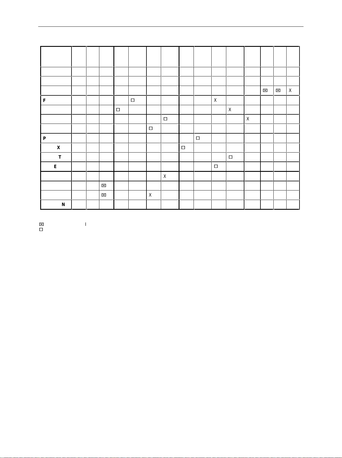
Modulation Sources SME
Table 2-3 Modulations which cannot be operated simultaneously
AM INT1
AM INT2
AM EXT1
FM1 INT1
FM1 EXT1,2
FM2 INT2
FM2 EXT1,2
PM1 INT1
PM1 EXT1,2
PM2 INT2
PM2 EXT1,2
Stereo
VOR
ILS
MKR-BCN
PM1
AM
INT1AMINT2AMEXT1FMINT1
X XXXXXX XXX
XX
XX
XXX X X X XX
x
x
FM1
EXT1,2
XX XX
XX XX
XX XX
XX XX
FM2
FM2
INT2
EXT1,
2
XXXXX
XXXXX
PM1
INT1
EXT1,2
XX XX
XX XX
X X X X X XXX
XX XX X
PM2
INT2
Stereo VOR ILS MCR
PM2
EXT1,
2
X XXX
X
X
X XXX
X
XXX
xx
BCN
X
X Mutual switching of f i n the case of manual control
x
in the VOR-(ILS..) m enu AM EXT can be added as an own parameter
Switching off by means of 1-out-of-n selection
2.6.1.3 [MOD ON/OFF] Key
The modulations can directly be switched on/off using the key [MOD ON/OFF] or by accessing the
MODULATION menu. When switching on using the [MOD O N/OFF] key, the m odulation s ources which
are set in the modulation menus are used.
The [MOD ON/OFF] key can either be effec tive for all modulations or for a selected m odulation. The
selection for which modulation the [MOD ON/OFF] k ey is effective is m ade in the UT ILITIES- MOD KEY
menu (cf. Section " Assigning Modulation to [MOD ON/OFF] Key").
When selecting a certain type of modulation, each press ing the [MOD ON/OFF] key switches on or off
the modulation selected.
In the case of selection "all modulations", the [MOD ON/OFF] key has the following effect:
• At least one modulation is active:
Pressing the [MOD ON/OFF] key switches off all active modulations. Which modulations were active
is stored.
• No modulation is active:
Pressing the [MOD ON/OFF] key switches on the modulations which were last switched off using the
[MOD ON/OFF] key.
1038.6002.02 2.52 E-13

SME Analog Modulations
2.6.2 Analog Modulation
2.6.2.1 LF-Generator
The SME is equipped with a fixed-frequency generator as internal modulation source as a standard. The
generator supplies sinusoidal signals of the frequencies of 0.4, 1, 3 and 15 kHz.
In addition to the standard equipment, the SME can be equipped with the following optional
LF modulation sources:
• LF-generator, option SM-B2
• Multifunction generator, option SM-B6
It is possible to fit two optional modulation sources unless option SM-B3, pulse modulator, is fitted. If two
options are fitted, the access to the internal s tandard generator is eliminated. T he different pos sibilities
of modulation generator fitting are visible from table 2-4:
Table 2-4 Modulation generators as component parts
LF-Generator 1 LF-Generator 2
Standard generator
Standard generator Option SM-B2, LF-generator
Standard generator Option SM-B6, multifunction generator
Option SM-B2, LF-generator Option SM-B2, LF-generator
Option SM-B2, LF-generator Option SM-B6, multifunction generator
The selection of the waveform and frequency of the internal modulation s ignals can be made in one of
the modulation menus ( AM, FM, PM) as well as in the LF-output menu.
---
Notes: - In conformanc e to the possibilities of the modulation generator options fitted, there are
differences in the modulation menus for AM, FM and PM.
- The following modulations cannot be set simultaneously and deactivate one another:
LFGEN SHAPE NOI and LF sweep.
1038.6002.02 2.53 E-13

Analog Modulations SME
2.6.2.2 Amplitude Modulation
Menu MODULATION-AM offers access to settings for amplitude modulation.
Notes:
-
In the level range from 7 to 13 dBm, the specified AM data are only guaranteed for a
linearly decreasing modulation depth with a rising level. W hen a modulation depth is s et
that is too high, "WARNING" is displayed in the s tatus line or the message "WARN - 221
Settings conflict; modulation forces peak level into overrange" is displayed after
pressing the ERROR key.
- Modulations AM, VOR, ILS and MKR BCN deactivate one another. AM SOURCE INT =
LFGEN2 and STEREO deactivate one another as well
Menu selection: MODULATION- AM
FREQ
FREQUENCY
LEVEL
MODULATION
DIGITAL MOD
LF OUTPUT
SWEEP
LIST
MEM SEQ
UTILITIES
HELP
100. 000 000 0
AM
FM
PM
PULSE
AM DE PT H
AM SOURCE INT
AM SOURCE EXT
AM EXT COUPLING
AM POLARITY
LFGEN1 FREQ
LFGEN2 FREQ
LFGEN2 SHAPE
MHz
.
LEVEL
30.0 %
OFF LFGEN1 LFGEN2
OFF EXT1
AC DC
NORM INV
0.4k 1k 3k 15k Hz
1.000 0 kHz
SIN SQR TRI NOI
- 30.0
dBm
Fig. 2-24 Menu MODULATION-AM (preset setting), fitted with option SM-B2, LF-generator
(LFGEN2)
AM DEPTH
Input value of the modulation depth..
IEC-bus command SOUR:AM 30PCT
AM SOURCE INT
Selection of the internal source.
IEC-bus command SOUR:AM:SOUR INT1; STAT ON
AM SOURCE EXT
Selection of the external source.
IEC-bus command SOUR:AM:SOUR EXT; STAT ON
AM EXT COUPLING
Selection of the kind of coupling AC or DC with external supply (input EXT1).
IEC-bus command SOUR:AM:EXT:COUP AC
1038.6002.02 2.54 E-13
 Loading...