


R&S®SMCVB-K164
DVB-T2
User Manual
(;Ý9Ø2)
1179097402
Version 04

This document describes the following software options:
●
R&S®SMCVB-K164 DVB-T2 (1434.3890.xx)
This manual describes firmware version FW 5.00.122.xx and later of the R&S®SMCV100B.
© 2022 Rohde & Schwarz GmbH & Co. KG
Muehldorfstr. 15, 81671 Muenchen, Germany
Phone: +49 89 41 29 - 0
Email: info@rohde-schwarz.com
Internet: www.rohde-schwarz.com
Subject to change – data without tolerance limits is not binding.
R&S® is a registered trademark of Rohde & Schwarz GmbH & Co. KG.
Trade names are trademarks of the owners.
1179.0974.02 | Version 04 | R&S®SMCVB-K164
The following abbreviations are used throughout this manual: R&S®SMCV100B is abbreviated as R&S SMCVB, R&S®WinIQSIM2 is
abbreviated as R&S WinIQSIM2

R&S®SMCVB-K164
Contents
1 Welcome to the DVB-T2 option.............................................................7
1.1 Accessing the DVB-T2 dialog...................................................................................... 7
1.2 What's new.....................................................................................................................7
1.3 Documentation overview..............................................................................................7
1.3.1 Getting started manual....................................................................................................8
1.3.2 User manuals and help................................................................................................... 8
1.3.3 Service manual............................................................................................................... 8
1.3.4 Instrument security procedures.......................................................................................8
1.3.5 Printed safety instructions............................................................................................... 9
1.3.6 Data sheets and brochures............................................................................................. 9
1.3.7 Release notes and open source acknowledgment (OSA).............................................. 9
Contents
1.3.8 Application notes, application cards, white papers, etc...................................................9
1.4 Scope........................................................................................................................... 10
1.5 Notes on screenshots.................................................................................................10
2 About the DVB-T2 option.....................................................................11
2.1 Required options.........................................................................................................11
3 DVB-T2 configuration and settings.................................................... 12
3.1 General settings.......................................................................................................... 12
3.2 Input signal settings................................................................................................... 15
3.2.1 General settings............................................................................................................ 16
3.2.2 PLP info.........................................................................................................................19
3.2.3 T2-MI data packet timing settings................................................................................. 21
3.2.4 Test signal settings........................................................................................................24
3.2.5 IP channel x settings..................................................................................................... 26
3.3 Mode & stream settings..............................................................................................29
3.3.1 PLP 0 settings............................................................................................................... 29
3.3.2 PLP info.........................................................................................................................31
3.4 BICM settings.............................................................................................................. 34
3.4.1 PLP 0 settings............................................................................................................... 35
3.4.2 PLP info.........................................................................................................................37
3.5 OFDM settings.............................................................................................................38
3User Manual 1179.0974.02 ─ 04

R&S®SMCVB-K164
3.6 System settings...........................................................................................................42
3.6.1 Network settings............................................................................................................42
3.6.2 L1 settings.....................................................................................................................46
3.6.3 ID settings..................................................................................................................... 48
3.7 SFN settings................................................................................................................ 49
3.7.1 Delays........................................................................................................................... 50
3.7.2 Mode............................................................................................................................. 51
3.8 Frame info....................................................................................................................53
3.8.1 Frame............................................................................................................................53
3.8.2 Symbols........................................................................................................................ 54
3.8.3 L1 signaling................................................................................................................... 55
3.8.4 Data cells...................................................................................................................... 56
3.9 Data generation settings............................................................................................ 57
Contents
3.10 Global connector settings..........................................................................................58
3.11 TS player......................................................................................................................58
3.11.1 TS Player settings......................................................................................................... 60
3.11.2 Player output settings....................................................................................................63
3.11.3 Seamless loop settings................................................................................................. 66
3.12 Local IP data network settings.................................................................................. 68
4 Performing DVB-T2 signal generation tasks..................................... 71
4.1 Configuring the input signal...................................................................................... 71
4.1.1 How to apply an external IP input signal....................................................................... 71
4.1.2 How to apply an external TS input signal......................................................................74
4.1.3 How to generate an internal TS signal.......................................................................... 75
4.2 Monitoring the input signal........................................................................................ 76
4.2.1 How to monitor external IP input data........................................................................... 76
4.2.2 How to monitor an external TS input signal.................................................................. 77
4.2.3 How to monitor an internal TS player signal................................................................. 77
5 Remote-control commands.................................................................78
5.1 General commands.....................................................................................................79
5.2 Input commands......................................................................................................... 81
5.2.1 General commands.......................................................................................................81
5.2.2 PLP info commands...................................................................................................... 85
4User Manual 1179.0974.02 ─ 04

R&S®SMCVB-K164
5.2.3 T2-MI packet timing commands.................................................................................... 88
5.2.4 Test signal commands...................................................................................................90
5.2.5 IP subsystem.................................................................................................................92
5.3 Mode and stream commands.....................................................................................96
5.4 BICM commands....................................................................................................... 102
5.5 OFDM commands......................................................................................................106
5.6 System commands....................................................................................................110
5.6.1 Network commands.....................................................................................................110
5.6.2 L1 commands..............................................................................................................115
5.6.3 ID commands.............................................................................................................. 119
5.7 SFN delay commands...............................................................................................120
5.8 Frame info commands..............................................................................................125
5.8.1 Frame and symbol duration commands......................................................................126
Contents
5.8.2 L1 signaling commands.............................................................................................. 128
5.8.3 Data cell commands....................................................................................................130
5.9 TSGen subsystem.....................................................................................................130
5.10 BCIP subsystem........................................................................................................138
Annex.................................................................................................. 142
A DVB-T2 test cases..............................................................................142
Glossary: Abbreviations....................................................................143
Glossary: Specifications................................................................... 146
List of commands.............................................................................. 147
Index....................................................................................................151
5User Manual 1179.0974.02 ─ 04

R&S®SMCVB-K164
Contents
6User Manual 1179.0974.02 ─ 04

R&S®SMCVB-K164
1 Welcome to the DVB-T2 option
The R&S SMCVB-K164 is a firmware application that adds functionality to generate
signals in accordance with the DVB-T2 digital standard.
Key features
The R&S SMCVB-K164 option features:
●
This user manual contains a description of the functionality that the application provides, including remote control operation.
All functions not discussed in this manual are the same as in the base unit and are
described in the R&S SMCV100B user manual. The latest version is available at:
www.rohde-schwarz.com/manual/SMCV100B
Installation
Welcome to the DVB-T2 option
Documentation overview
DVB-T2 signal generation
You can find detailed installation instructions in the delivery of the option or in the
R&S SMCV100B service manual.
1.1 Accessing the DVB-T2 dialog
To open the dialog with DVB-T2 settings
► In the block diagram of the R&S SMCV100B, select "Baseband > DVB-T2".
A dialog box opens that displays the provided general settings.
The signal generation is not started immediately. To start signal generation with the
default settings, select "State > On".
1.2 What's new
This manual describes firmware version FW 5.00.122.xx and later of the
R&S®SMCV100B.
Compared to the previous version there are editorial changes only.
1.3 Documentation overview
This section provides an overview of the R&S SMCV100B user documentation. Unless
specified otherwise, you find the documents on the R&S SMCV100B product page at:
7User Manual 1179.0974.02 ─ 04

R&S®SMCVB-K164
www.rohde-schwarz.com/manual/smcv100b
1.3.1 Getting started manual
Introduces the R&S SMCV100B and describes how to set up and start working with the
product. Includes basic operations, typical measurement examples, and general information, e.g. safety instructions, etc. A printed version is delivered with the instrument.
1.3.2 User manuals and help
Separate manuals for the base unit and the software options are provided for download:
●
●
Welcome to the DVB-T2 option
Documentation overview
Base unit manual
Contains the description of all instrument modes and functions. It also provides an
introduction to remote control, a complete description of the remote control commands with programming examples, and information on maintenance, instrument
interfaces and error messages. Includes the contents of the getting started manual.
Software option manual
Contains the description of the specific functions of an option. Basic information on
operating the R&S SMCV100B is not included.
The contents of the user manuals are available as help in the R&S SMCV100B. The
help offers quick, context-sensitive access to the complete information for the base unit
and the software options.
All user manuals are also available for download or for immediate display on the Internet.
1.3.3 Service manual
Describes the performance test for checking compliance with rated specifications, firmware update, troubleshooting, adjustments, installing options and maintenance.
The service manual is available for registered users on the global Rohde & Schwarz
information system (GLORIS):
https://gloris.rohde-schwarz.com
1.3.4 Instrument security procedures
Deals with security issues when working with the R&S SMCV100B in secure areas. It
is available for download on the Internet.
8User Manual 1179.0974.02 ─ 04

R&S®SMCVB-K164
1.3.5 Printed safety instructions
Provides safety information in many languages. The printed document is delivered with
the product.
1.3.6 Data sheets and brochures
The data sheet contains the technical specifications of the R&S SMCV100B. It also
lists the options and their order numbers and optional accessories.
The brochure provides an overview of the instrument and deals with the specific characteristics.
See www.rohde-schwarz.com/brochure-datasheet/smcv100b
1.3.7 Release notes and open source acknowledgment (OSA)
The release notes list new features, improvements and known issues of the current
firmware version, and describe the firmware installation.
Welcome to the DVB-T2 option
Documentation overview
The open-source acknowledgment document provides verbatim license texts of the
used open source software.
See www.rohde-schwarz.com/firmware/smcv100b
1.3.8 Application notes, application cards, white papers, etc.
These documents deal with special applications or background information on particular topics.
See www.rohde-schwarz.com/application/smcv100b
9User Manual 1179.0974.02 ─ 04

R&S®SMCVB-K164
1.4 Scope
Tasks (in manual or remote operation) that are also performed in the base unit in the
same way are not described here.
In particular, it includes:
●
●
●
●
For a description of such tasks, see the R&S SMCV100B user manual.
Welcome to the DVB-T2 option
Notes on screenshots
Managing settings and data lists, like saving and loading settings, creating and
accessing data lists, or accessing files in a particular directory.
Information on regular trigger, marker and clock signals and filter settings, if appropriate.
General instrument configuration, such as checking the system configuration, configuring networks and remote operation
Using the common status registers
1.5 Notes on screenshots
When describing the functions of the product, we use sample screenshots. These
screenshots are meant to illustrate as many as possible of the provided functions and
possible interdependencies between parameters. The shown values may not represent
realistic usage scenarios.
The screenshots usually show a fully equipped product, that is: with all options installed. Thus, some functions shown in the screenshots may not be available in your particular product configuration.
10User Manual 1179.0974.02 ─ 04

R&S®SMCVB-K164
2 About the DVB-T2 option
The transmission standard complies with the specification ETSI EN 302 755 and ETSI
TS 102 773. A subset of all possible parameters found in the specification can be set
on the R&S SMCV100B.
2.1 Required options
The equipment layout for generating DVB-T2 signals includes:
●
●
●
About the DVB-T2 option
Required options
Base unit
Option Enable Broadcast Standard (R&S SMCVB-K519)
Option DVB-T2 (R&S SMCVB-K164)
11User Manual 1179.0974.02 ─ 04
R&S®SMCVB-K164
3 DVB-T2 configuration and settings
This section provides an overview on the DVB-T2 settings.
Access:
► Select "Baseband > DVB-T2".
The remote commands required to define these settings are described in Chapter 5,
"Remote-control commands", on page 78.
Settings:
● General settings......................................................................................................12
● Input signal settings................................................................................................ 15
● Mode & stream settings.......................................................................................... 29
● BICM settings..........................................................................................................34
● OFDM settings........................................................................................................ 38
● System settings.......................................................................................................42
● SFN settings............................................................................................................49
● Frame info...............................................................................................................53
● Data generation settings......................................................................................... 57
● Global connector settings........................................................................................58
● TS player.................................................................................................................58
● Local IP data network settings................................................................................ 68
DVB-T2 configuration and settings
General settings
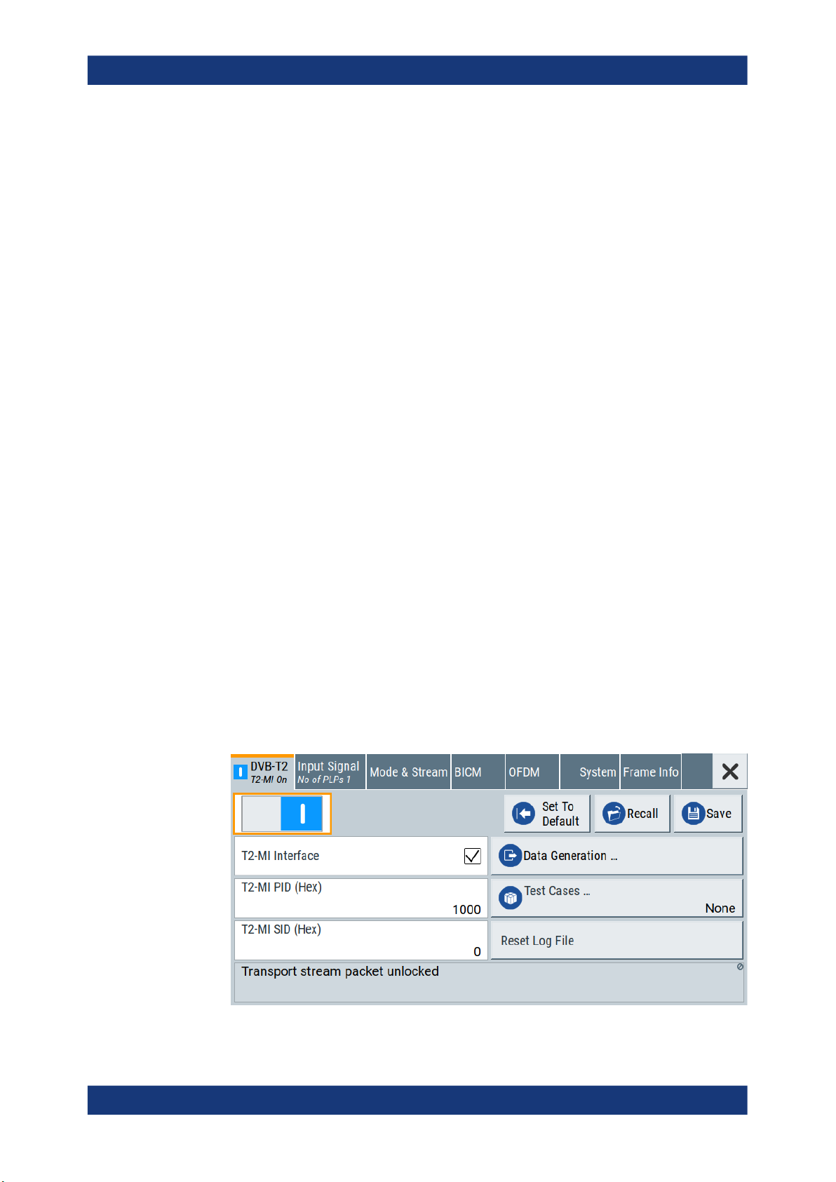
3.1 General settings
Access:
► Select "Baseband > DVB-T2".
12User Manual 1179.0974.02 ─ 04

R&S®SMCVB-K164
The remote commands required to define these settings are described in Chapter 5.1,
"General commands", on page 79.
Settings:
State..............................................................................................................................13
Set To Default................................................................................................................13
Save/Recall...................................................................................................................13
T2-MI Interface..............................................................................................................14
T2-MI PID (Hex)............................................................................................................14
T2-MI SID (Hex)............................................................................................................14
Data Generation............................................................................................................14
Test Cases.................................................................................................................... 14
Reset Log File...............................................................................................................14
Status Info.....................................................................................................................15
DVB-T2 configuration and settings
General settings
The tab provides default settings, save and recall settings and settings to configure
T2-MI interface parameters.
└ Filter Test Cases............................................................................................. 14
State
Activates the standard and deactivates all the other digital standards and digital modulation modes in the same path.
Remote command:
[:SOURce<hw>]:BB:T2DVb:STATe on page 79
Set To Default
Calls the default settings. The values of the main parameters are listed in the following
table.
Parameter Value
State Not affected by the "Set to Default"
Remote command:
[:SOURce<hw>]:BB:T2DVb:PRESet on page 79
Save/Recall
Accesses the "Save/Recall" dialog, that is the standard instrument function for saving
and recalling the complete dialog-related settings in a file. The provided navigation
possibilities in the dialog are self-explanatory.
The settings are saved in a file with predefined extension. You can define the filename
and the directory, in that you want to save the file.
See also, chapter "File and Data Management" in the R&S SMCV100B user manual.
Remote command:
[:SOURce<hw>]:BB:T2DVb:SETTing:CATalog? on page 80
[:SOURce<hw>]:BB:T2DVb:SETTing:DELete on page 80
[:SOURce<hw>]:BB:T2DVb:SETTing:LOAD on page 80
[:SOURce<hw>]:BB:T2DVb:SETTing:STORe on page 80
13User Manual 1179.0974.02 ─ 04

R&S®SMCVB-K164
T2-MI Interface
Activates the T2-MI modulator interface.
"On"
"Off"
Remote command:
[:SOURce<hw>]:BB:T2DVb:INPut:T2MI:INTerface on page 83
T2-MI PID (Hex)
Requires "T2-MI Interface > On".
Sets the PID.
The PID belongs to MPEG transport stream packets, that contain T2-MI data.
Remote command:
[:SOURce<hw>]:BB:T2DVb:INPut:T2MI:PID on page 83
T2-MI SID (Hex)
Requires "T2-MI Interface > On".
Sets the T2-MI transport SID.
Use the SID, when transmitting a composite signal, in accordance with annex I of the
specification ETSI EN 302 755.
Remote command:
[:SOURce<hw>]:BB:T2DVb:INPut:T2MI:SID on page 84
DVB-T2 configuration and settings
General settings
Uses the incoming T2-MI stream to configure the modulator.
Uses the incoming MPEG transport stream directly as payload for
single PLP transmission.
Data Generation
Accesses the "DVB-T2 Data Generation" dialog.
See Chapter 3.9, "Data generation settings", on page 57.
Test Cases
Accesses a standard file-select dialog to select DVB-T2 test cases.
For available test cases, see Chapter A, "DVB-T2 test cases", on page 142.
Filter Test Cases ← Test Cases
Filters the list of available test cases.
Reset Log File
Requires "T2-MI Interface > On".
Resets the log file.
Status information of the T2-MI analyzer as displayed in "Status Info" is saved to a log
file. The log file DVBT2_T2MI_Status_Info_TX.txt is saved to the directory var/
user/log.
See also, chapter "File and Data Management" in the R&S SMCV100B user manual.
Remote command:
[:SOURce<hw>]:BB:T2DVb:INPut:T2MI:RESetlog on page 84
14User Manual 1179.0974.02 ─ 04

R&S®SMCVB-K164
Status Info
Displays the status of the T2-MI analyzer by an error message. "No Error" implies correct behavior of the analyzer. Status information of the T2-MI analyzer is saved to a log
file, see "Reset Log File" on page 14.
To ensure correct behavior, fix occurring errors successively.
Remote command:
[:SOURce<hw>]:BB:T2DVb:INPut:T2MI:ANALyzer? on page 83
3.2 Input signal settings
Access:
► Select "Baseband > DVB-T2 > Input Signal".
DVB-T2 configuration and settings
Input signal settings
The dialog provides settings to configure the input signal.
Input signal tasks
The settings allow you to perform the following tasks:
●
Selecting an MPEG TS or T2-MI source
●
Displaying information about the selected stream (e.g. data rate)
●
Configuring the internal MPEG TS test packets
How to: Chapter 4.1, "Configuring the input signal", on page 71
Settings:
● General settings......................................................................................................16
● PLP info...................................................................................................................19
● T2-MI data packet timing settings........................................................................... 21
● Test signal settings..................................................................................................24
● IP channel x settings...............................................................................................26
15User Manual 1179.0974.02 ─ 04
R&S®SMCVB-K164
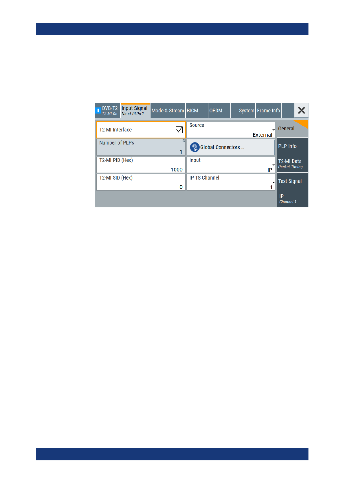
3.2.1 General settings
Access:
► Select "Input Signal > General".
DVB-T2 configuration and settings
Input signal settings
The tab provides general settings to configure the input signal.
Settings:
T2-MI Interface..............................................................................................................16
Source...........................................................................................................................16
Number of PLPs............................................................................................................17
Input.............................................................................................................................. 17
Input Format..................................................................................................................17
IP TS Channel...............................................................................................................18
T2-MI PID (Hex)............................................................................................................18
T2-MI SID (Hex)............................................................................................................18
Stuffing..........................................................................................................................18
Test Signal.....................................................................................................................18
T2-MI Interface
Activates the T2-MI modulator interface.
"On"
"Off"
Remote command:
[:SOURce<hw>]:BB:T2DVb:INPut:T2MI:INTerface on page 83
Uses the incoming T2-MI stream to configure the modulator.
Uses the incoming MPEG transport stream directly as payload for
single PLP transmission.
Source
Sets the modulation source for the input signal.
16User Manual 1179.0974.02 ─ 04

R&S®SMCVB-K164
DVB-T2 configuration and settings
Input signal settings
"External"
"TS Player"
"Test Signal"
Remote command:
[:SOURce<hw>]:BB:T2DVb:SOURce on page 82
Number of PLPs
Displays the number of PLPs.
The available number of PLPs depends on the setting of "T2-MI Interface":
●
If "T2-MI Interface > Off", the number of PLPs is "1" (single PLP).
●
If "T2-MI Interface > On", maximum "1 to 20" PLPs are supported.
Remote command:
[:SOURce<hw>]:BB:T2DVb:INPut:NPLP? on page 86
Uses a transport stream, that is input at the "TS IN"/"IP Data" interface.
For more information about connecting to the interfaces, see also:
●
"TS IN" interface: Section "Configuring the Global Connectors" in
the R&S SMCV100B user manual.
●
"IP Data" interface: Chapter 3.12, "Local IP data network set-
tings", on page 68.
Uses an internal transport stream with TS packet data played from a
file. The player requires no option.
Playing encrypted files with extension _c requires a stream library
option R&S SMCVB-KSx.
See also:
●
Chapter 3.11, "TS player", on page 58
●
Supported TS player file types
Requires "T2-MI Interface > Off".
Uses an internal test signal as specified in Chapter 3.2.4, "Test signal
settings", on page 24.
Input
Requires "Source > External".
Sets the external input interface.
"TS IN"
"IP"
Remote command:
[:SOURce<hw>]:BB:T2DVb:INPut on page 82
Input Format
Requires "Source > External" and "Input > TS IN".
Sets the format of the input signal.
"ASI"
"SMPTE 310"
Remote command:
[:SOURce<hw>]:BB:T2DVb:INPut:FORMat on page 83
Input for serial transport stream data. The signal is input at the "User
1" connector.
Input for IP-based transport stream data (TSoverIP). The signal is
input at the "IP Data" connector.
ASI format
SMPTE 310 format
17User Manual 1179.0974.02 ─ 04

R&S®SMCVB-K164
IP TS Channel
Requires "Source > External" and "Input > IP".
Selects the IP-based transport stream (TS) channel. You can select 1 out of 4 IP TS
channels as input at the "IP Data" interface.
To configure a particular channel, see Chapter 3.2.5, "IP channel x settings",
on page 26.
Remote command:
[:SOURce<hw>]:BB:T2DVb:INPut:TSCHannel on page 84
T2-MI PID (Hex)
Requires "T2-MI Interface > On".
Sets the PID.
The PID belongs to MPEG transport stream packets, that contain T2-MI data.
Remote command:
[:SOURce<hw>]:BB:T2DVb:INPut:T2MI:PID on page 83
T2-MI SID (Hex)
Requires "T2-MI Interface > On".
Sets the T2-MI transport SID.
Use the SID, when transmitting a composite signal, in accordance with annex I of the
specification ETSI EN 302 755.
Remote command:
[:SOURce<hw>]:BB:T2DVb:INPut:T2MI:SID on page 84
DVB-T2 configuration and settings
Input signal settings
Stuffing
Requires "External/TS Player" and "T2-MI Interface > Off".
Activates stuffing.
"On"
"Off"
Remote command:
[:SOURce<hw>]:BB:T2DVb:PLP<ch>:INPut:STUFfing on page 87
Test Signal
Requires "T2-MI Interface > Off" and "Source > Test Signal".
Defines the test signal data.
"Test TS Packet"
Remote command:
[:SOURce<hw>]:BB:T2DVb:PLP<ch>:INPut:TESTsignal on page 91
Inserts null packets and corrects the PCR values.
The data rate of the transport stream source must match the data
rate required for the current modulation parameters.
Standardized packet data used as modulation data in the transport
stream. To configure the packet structure, select the side tab "Test
Signal > Test TS Packet".
Uses a null packet as the test signal. To configure the null packet, see
Chapter 3.2.4, "Test signal settings", on page 24.
18User Manual 1179.0974.02 ─ 04

R&S®SMCVB-K164
3.2.2 PLP info
Access:
► Select "Input Signal > PLP Info".
Settings:
PLP <num> table.......................................................................................................... 19
DVB-T2 configuration and settings
Input signal settings
The tab displays the "PLP <num>" table, that contains individual PLP information of
up to 20 PLPs.
The information comprises input parameters for each PLP.
└ PLP Input Format............................................................................................19
└ Packet Length.................................................................................................19
└ Stuffing............................................................................................................20
└ Max. Useful Data Rate / Mbit/s....................................................................... 20
└ Measured Data Rate / Mbit/s.......................................................................... 20
└ Useful Data Rate / Mbit/s................................................................................20
PLP <num> table
Displays individual parameters for each PLP <num>. The table displays information of
up to 20 PLPs with <num> ranging from 0 to 19.
PLP Input Format ← PLP <num> table
Displays the input format of each PLP <num> for all input sources.
"GFPS/GCS/GSE" require "T2-MI Interface > On".
To edit the input format, select "Input Signal > General > Input Format".
"TS"
"GFPS"
"GCS"
"GSE"
Remote command:
[:SOURce<hw>]:BB:T2DVb:PLP<ch>:INPut:FORMat on page 86
Packet Length ← PLP <num> table
Requires "T2-MI Interface > Off" and "Source > External".
Displays the packet length of the external transport stream in bytes.
If the packet length does not match the specified length, the output signal is erroneous.
"Packet Length > Invalid" is displayed.
Transport stream
Generic fixed-length packetized stream
Generic continuous stream
Generic stream encapsulation
19User Manual 1179.0974.02 ─ 04

R&S®SMCVB-K164
DVB-T2 configuration and settings
Input signal settings
"188"
188 byte packets specified for serial input ("Input > TS IN") and parallel input ("Input > IP").
"Invalid"
Packet length ≠ 188 bytes, i.e. the length is not a specified length.
Remote command:
[:SOURce<hw>]:BB:T2DVb:PLP<ch>:PACKetlength? on page 87
Stuffing ← PLP <num> table
Requires "External/TS Player" and "T2-MI Interface > Off".
Activates stuffing.
"On"
"Off"
Inserts null packets and corrects the PCR values.
The data rate of the transport stream source must match the data
rate required for the current modulation parameters.
Remote command:
[:SOURce<hw>]:BB:T2DVb:PLP<ch>:INPut:STUFfing on page 87
Max. Useful Data Rate / Mbit/s ← PLP <num> table
Requires "T2-MI Interface > Off" and "Source > External/TS Player".
Displays the maximum data rate, that is derived from the current modulation parameter
settings.
The value is the optimal value at the TS input interface, that is necessary for the modu-
lator.
Remote command:
[:SOURce<hw>]:BB:T2DVb:PLP<ch>:USEFul[:RATE]:MAX? on page 88
Measured Data Rate / Mbit/s ← PLP <num> table
Requires "T2-MI Interface > Off" and "Source > External".
Displays the measured value of the data rate r
●
External transport stream including null packets input at "User 1" connector
●
External transport stream including null packets input at "IP Data/LAN" connector
of one of the following:
meas
(TSoverIP)
The value r
r
= r
meas
useful
equals the sum of useful data rate r
meas
+ r
0
and the rate of null packets r0:
useful
Remote command:
[:SOURce<hw>]:BB:T2DVb:PLP<ch>[:INPut]:DATarate? on page 88
Useful Data Rate / Mbit/s ← PLP <num> table
Requires "Source > External/TS Player".
Displays the data rate of useful data r
of the external transport stream. The data
useful
rate is measured at the input of the installed input interface.
The value is measured or computed depending on the setting of "T2-MI Interface":
●
If "T2-MI Interface > Off" and "Source > External/TS Player", the value is measured.
●
If "T2-MI Interface > On", the value is computed.
20User Manual 1179.0974.02 ─ 04
R&S®SMCVB-K164
Remote command:
[:SOURce<hw>]:BB:T2DVb:PLP<ch>:USEFul[:RATE]? on page 87
3.2.3 T2-MI data packet timing settings
Access:
1. Select "Input Signal > T2-MI Interface > On".
2. Select "Input Signal > T2-MI Data Packet Timing"
DVB-T2 configuration and settings
Input signal settings
The "T2-MI Data Packet Timing" side-tab appears.
The tab provides packet timing settings for data input at the T2-MI interface.
All operations on frame_idx are modulo NT2.
Individual addressing functions (packet_type 2116) can be sent at any time.
The T2 timestamp refers to the transmission time of the super frame, although it is sent
at any time.
The figure below shows a single PLP. If using multiple PLPs, the interleaving frame
duration TIF and hence the timing requirements for the type 0016 packets can be different for different PLPs.
21User Manual 1179.0974.02 ─ 04
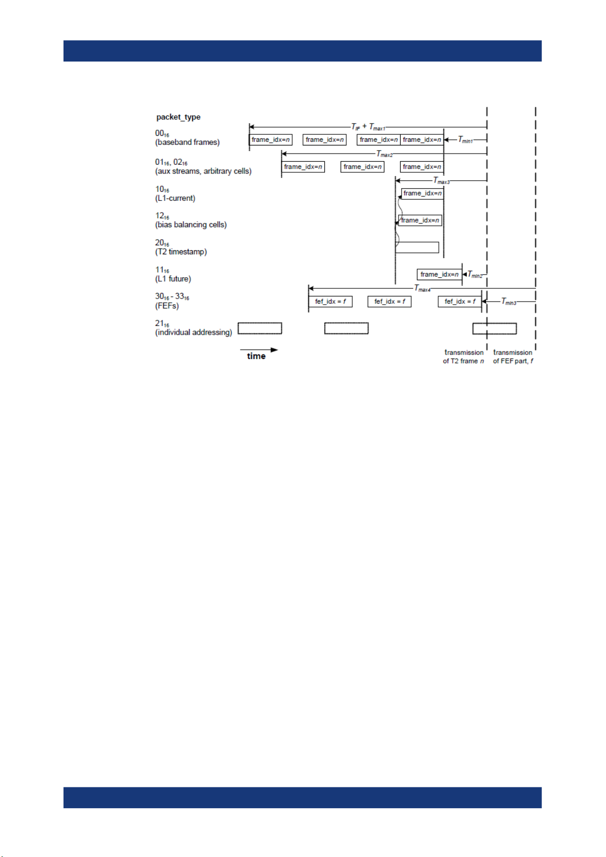
R&S®SMCVB-K164
DVB-T2 configuration and settings
Input signal settings
Settings:
All following settings require "T2-MI Interface > On".
Measurement Mode...................................................................................................... 22
T2-MI T
T2-MI T
T2-MI T
T2-MI T
T2-MI T
T2-MI T
T2-MI T
.................................................................................................................... 22
min1
.................................................................................................................... 23
min2
.................................................................................................................... 23
min3
....................................................................................................................23
max1
....................................................................................................................23
max2
....................................................................................................................24
max3
....................................................................................................................24
max4
Measurement Mode
Specifies the measurement mode to configure the evaluation of T2-MI timing parameters.
"Absolute"
Displays the absolute values of the measured T2-MI timing parameters.
"Delta"
Displays the measured delta values of two consecutive T2-MI packets for each T2-MI timing parameter.
Remote command:
[:SOURce<hw>]:BB:T2DVb:INPut:T2MI:MEASuremode on page 89
T2-MI T
min1
Displays the current value of T
min1
.
22User Manual 1179.0974.02 ─ 04

R&S®SMCVB-K164
DVB-T2 configuration and settings
Input signal settings
T2-MI packets arrive at the modulator not later than T
before starting transmission
min1
of the corresponding T2 frame, if:
●
T2-MI packets are of type: 0016, 0116, 0216, 1016, 1216, 20
●
frame_idx is given
16
Remote command:
[:SOURce<hw>]:BB:T2DVb:INPut:T2MI:MIN:T1? on page 89
T2-MI T
Displays the current value of T
T2-MI packets arrive at the modulator not later than T
min2
min2
.
before starting transmission
min2
of the corresponding T2 frame, if:
●
T2-MI packets are of type: 11
●
frame_idx is given
16
Remote command:
[:SOURce<hw>]:BB:T2DVb:INPut:T2MI:MIN:T2? on page 89
T2-MI T
Displays the current value of T
T2-MI packets arrive at the modulator not later than T
min3
min3
.
before starting transmission
min3
of the corresponding FEF part, if:
●
T2-MI packets are of type: 3016, 3116, 3216, 33
●
fef_idx is given
16
Remote command:
[:SOURce<hw>]:BB:T2DVb:INPut:T2MI:MIN:T3? on page 89
T2-MI T
Displays the current value of T
T2-MI packets arrive at the modulator not earlier than TIF + T
max1
max1
.
before starting trans-
max1
mission of the corresponding T2 frame, if:
●
T2-MI packets are of type: 0016 type
●
frame_idx is given
TIF is the duration of one interleaving frame for the corresponding PLP.
Remote command:
[:SOURce<hw>]:BB:T2DVb:INPut:T2MI:MAX:T1? on page 90
T2-MI T
Displays the current value of T
T2-MI packets arrive at the modulator not earlier than T
max2
max2
.
before starting transmis-
max2
sion of the corresponding T2 frame, if:
●
T2-MI packets are of type: 0116, 02
●
frame_idx is given
16
Remote command:
[:SOURce<hw>]:BB:T2DVb:INPut:T2MI:MAX:T2? on page 90
23User Manual 1179.0974.02 ─ 04
R&S®SMCVB-K164
DVB-T2 configuration and settings
Input signal settings
T2-MI T
max3
Displays the current value of T
T2-MI packets arrive at the modulator not earlier than T
sion of the corresponding T2 frame, if:
●
T2-MI packets are of type: 1016, 1116, 1216, 20
●
frame_idx is given
Remote command:
[:SOURce<hw>]:BB:T2DVb:INPut:T2MI:MAX:T3? on page 90
T2-MI T
max4
Displays the current value of T
T2-MI packets arrive at the modulator not earlier than T
sion of the corresponding FEF part, if:
●
One of the following types: 3016, 3116, 3216, 33
●
Given fef_idx
Remote command:
[:SOURce<hw>]:BB:T2DVb:INPut:T2MI:MAX:T4? on page 90
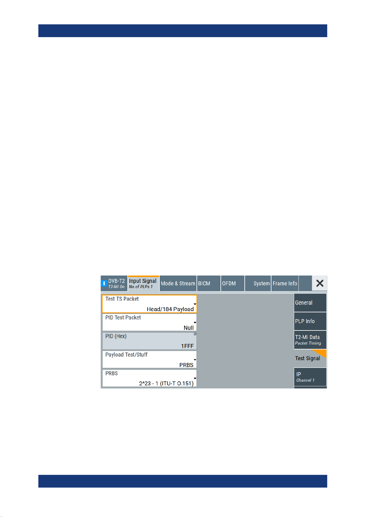
3.2.4 Test signal settings
max3
max4
.
before starting transmis-
max3
16
.
before starting transmis-
max4
16
Access:
► Select "Input Signal > Test Signal".
The tab provides settings to configure the test signal.
24User Manual 1179.0974.02 ─ 04

R&S®SMCVB-K164
Settings:
Test TS Packet..............................................................................................................25
PID Test Packet.............................................................................................................25
PID (Hex)...................................................................................................................... 25
Payload Test/Stuff......................................................................................................... 25
PRBS............................................................................................................................ 25
Test TS Packet
Specifies the structure of the test transport stream packet that is fed to the modulator.
"Head/184 Payload"
"Sync/187 Payload"
Remote command:
[:SOURce<hw>]:BB:T2DVb:TSPacket on page 92
DVB-T2 configuration and settings
Input signal settings
A sync byte (0x47) followed by three header bytes and 184 payload
bytes.
A sync byte (0x47) followed by 187 payload bytes.
PID Test Packet
If a header is present in the test packet ("Test TS Packet > Head/184 Payload"), you
can specify a fixed or variable packet identifier (PID).
"Null"
"Variable"
Remote command:
[:SOURce<hw>]:BB:T2DVb:PIDTestpack on page 91
PID (Hex)
Sets the PID.
If "PID Test Packet > Null", "PID (Hex) = 1FFF" is fixed.
If "PID Test Packet > Variable", you can edit the value.
Remote command:
[:SOURce<hw>]:BB:T2DVb:PID on page 91
Payload Test/Stuff
Defines the payload area content of the TS packet.
You can select PRBS or exclusively data in hexadecimal format as payload.
For "Source > Test Signal", the packet is a test packet.
For "Stuffing > On", the packet is a null packet. Null packets are inserted into the exter-
nal transport stream to adapt the stream data rate. See also "Measured Data Rate /
Mbit/s" on page 20
Remote command:
[:SOURce<hw>]:BB:T2DVb:PAYLoad on page 91
The header of the test transport stream packets has a fixed setting of
null packet header 1FFF (hex).
Uses the header value defined with "PID (Hex)" on page 25.
PRBS
Sets the length of the PRBS sequence.
25User Manual 1179.0974.02 ─ 04
R&S®SMCVB-K164
You can select a PRBS 15 or a PRBS 23 sequence as specified by ITU-T O.151.
Remote command:
[:SOURce<hw>]:BB:T2DVb:PRBS[:SEQuence] on page 92
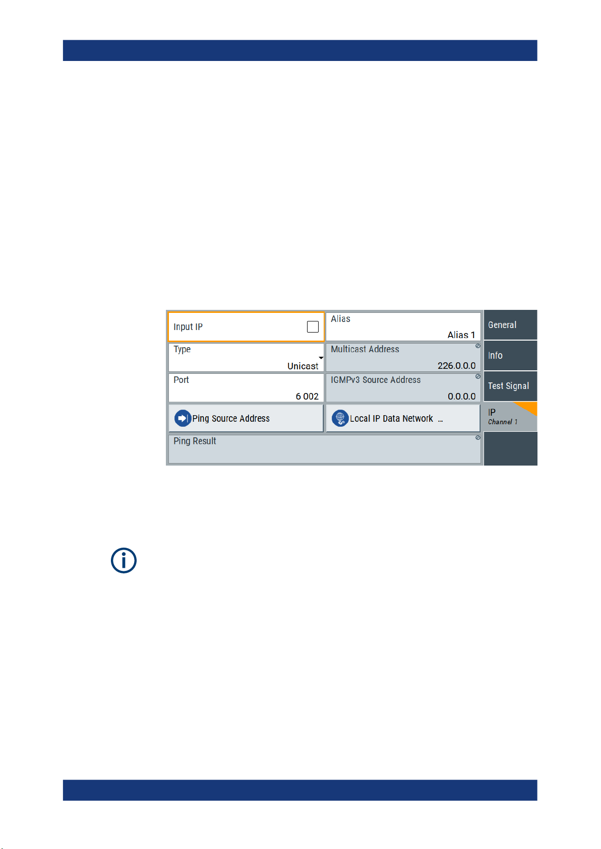
3.2.5 IP channel x settings
Access:
1. Select "Input Signal > General".
2. Select "Source > External"
3. Select "Input > IP"
4. Select "Input Signal > IP Channel x"
DVB-T2 configuration and settings
Input signal settings
The tab provides settings to configure IP channel x.
You can configure settings for 4 IP channels x = 1 to 4 individually, see also "Input
Signal > General > IP TS Channel".
IP channel settings affect input IP data of the local IP data network. The settings are
independent from the used broadcast standard configuration.
Saving/recalling a certain IP channel or local IP data network configuration is not possible via the broadcast standard-specific functionality.
Use the global save/recall functionality instead, see section "Saving and Recalling
Instrument Settings" in the R&S SMCV100B user manual.
The table below shows the availability of the tab in the broadcast standard configuration.
26User Manual 1179.0974.02 ─ 04

R&S®SMCVB-K164
Table 3-1: IP channel configuration support in broadcast standards
See also:
●
●
Requirements
DVB-T2 configuration and settings
Input signal settings
Baseband standard "IP Channel x" Baseband standard "IP Channel x"
"ATSC/ATSC-M/H" Yes "DVB-S" Yes
"ATSC 3.0" No "DVB-S2" Yes
"DTMB" Yes "DVB-C" Yes
"DVB-T" Yes "J.83/B" Yes
"DVB-T2" Yes "DRM" No
"ISDB-T" Yes "Audio AM" No
"T-DMB/DAB" Yes "Audio FM" No
Chapter 4.1.1, "How to apply an external IP input signal", on page 71
Chapter 3.12, "Local IP data network settings", on page 68
At your IP source, set the "transport stream packets per internet protocol packet" (TP
per IP) parameter as follows:
●
If TP packet length = 188 bytes: Set TP per IP to 7 or 6.
●
If TP packet length = 204/208 bytes: Set TP per IP to 6.
We recommend that you use a separate LAN infrastructure to stream the transport
streams via IP to the IP connector of the baseband board. Also, avoid TS packet losses during IP transmission.
Settings:
Input IP..........................................................................................................................27
Alias.............................................................................................................................. 27
Type.............................................................................................................................. 28
Multicast Address..........................................................................................................28
Port................................................................................................................................28
IGMPv3 Source Address...............................................................................................28
Ping Source Address.................................................................................................... 28
Ping Result....................................................................................................................28
Local IP Data Network.................................................................................................. 29
Input IP
Activates/deactivates the IP input.
Remote command:
[:SOURce<hw>]:BB:INPut:IP<ch>[:STATe] on page 93
Alias
Sets a unique name for the IP connection.
The definition of a name is optional but facilitates identification in the measurement
views. The name input fits maximum 16 characters in ASCII format.
27User Manual 1179.0974.02 ─ 04

R&S®SMCVB-K164
Remote command:
[:SOURce<hw>]:BB:INPut:IP<ch>:ALIas on page 94
Type
Sets the input signal type.
"Unicast"
"Multicast"
Remote command:
[:SOURce<hw>]:BB:INPut:IP<ch>:TYPE on page 94
Multicast Address
Editing requires "Type > Multicast".
Sets the destination IP address (IPv4) of the IP connection.
You can set addresses from "224.0.0.0" to "239.255.255.255".
Remote command:
[:SOURce<hw>]:BB:INPut:IP<ch>:MULticast:ADDRess on page 95
DVB-T2 configuration and settings
Input signal settings
Analyzes all unicast IP packets that arrive at the specified "Port".
When an IP address is in the multicast address range, an attempt is
made to join a multicast group using IGMP.
Set "Multicast Address" and "Port".
Port
Sets the destination UDP port.
Due to UDP/RTP autosensing, we recommend that you set a port offset of at least 6
between neighboring IP TS channels.
Remote command:
[:SOURce<hw>]:BB:INPut:IP<ch>:PORT on page 94
IGMPv3 Source Address
Requires "Type > Multicast".
Sets the IGMPv3 source address.
If you need to filter the data sent to the multicast address, specify the source address.
A source address different from "0.0.0.0" accepts only data originating from the specified IP address.
Remote command:
[:SOURce<hw>]:BB:INPut:IP<ch>:IGMP[:SOURce]:ADDRess on page 95
Ping Source Address
Clicking "Ping Source Address" triggers pinging of the IGMPv3 source address.
If you set a different value from "IGMPv3 Source Address = 0.0.0.0" and click the but-
ton, the software checks if the address is reachable.
Remote command:
[:SOURce<hw>]:BB:INPut:IP<ch>:IGMP[:SOURce]:PING on page 95
Ping Result
Displays the result after pinging the source address.
If "Ping Result > Ping: Successful", the source address is available in the network.
28User Manual 1179.0974.02 ─ 04
R&S®SMCVB-K164
If "Ping Result > Ping: Transmit Failed. xxx", the source address is not available in the
network. "xxx" can be, e.g. "General Failure". Try another "IGMPv3 Source Address".
Remote command:
[:SOURce<hw>]:BB:INPut:IP<ch>:IGMP[:SOURce]:RESult? on page 95
Local IP Data Network
Accesses local IP data network settings, see Chapter 3.12, "Local IP data network set-
tings", on page 68.
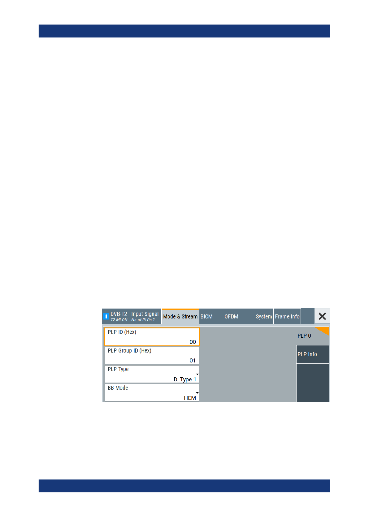
3.3 Mode & stream settings
Access:
► Select "Baseband > DVB-T2 > Mode & Stream".
DVB-T2 configuration and settings
Mode & stream settings
The tab provides settings to configure mode and stream adaptation parameters.
Settings:
● PLP 0 settings.........................................................................................................29
● PLP info...................................................................................................................31
3.3.1 PLP 0 settings
Access:
► Select "Mode & Stream > PLP 0".
The tab provides settings to configure mode and stream parameters of "PLP 0".
Editing "PLP 0" settings requires "T2-MI Interface > Off".
29User Manual 1179.0974.02 ─ 04

R&S®SMCVB-K164
Settings:
PLP ID (Hex).................................................................................................................30
PLP Group ID (Hex)......................................................................................................30
PLP Type.......................................................................................................................30
BB Mode....................................................................................................................... 30
PLP ID (Hex)
Sets the PLP ID. The PLP ID has to be unique.
You can set the PLP ID in hexadecimal representation.
Remote command:
[:SOURce<hw>]:BB:T2DVb:PLP<ch>:ID on page 99
PLP Group ID (Hex)
Sets the PLP group ID for multi-PLP, i.e. the number of PLPs is greater than 1.
Multi-PLP requires number of PLPs > 1, see "Number of PLPs" on page 17.
Remote command:
[:SOURce<hw>]:BB:T2DVb:PLP<ch>:GROup on page 98
DVB-T2 configuration and settings
Mode & stream settings
PLP Type
Sets the PLP type.
The type depends on the number of PLPs in the setup.
"Common"
"D. Type 1"
"D. Type 2"
Remote command:
[:SOURce<hw>]:BB:T2DVb:PLP<ch>:TYPE on page 101
BB Mode
Defines the baseband mode.
"HEM"
"NM"
Remote command:
[:SOURce<hw>]:BB:T2DVb:PLP<ch>:BB_Mode on page 97
Requires a multi-PLP setup.
Common PLP of the PLP Group.
Data type 1.
Fixed for a single-PLP setup. Configurable for a multi-PLP stream.
Requires a multi-PLP setup.
Data type 2.
High efficiency mode.
Normal mode.
30User Manual 1179.0974.02 ─ 04
 Loading...