


R&S®SMCV100B
Vector Signal Generator
User Manual
(;Ý5ï2)
1179059702
Version 04

This document describes the R&S®SMCV100B, stock no. 1432.7000.02 and its options:
●
R&S®SMCVB-B103 Frequency range 4 kHz to 3 GHz (1433.2002.xx)
●
R&S®SMCVB-KB106 Frequency range extension to 6 GHz (1433.2202.xx)
●
R&S®SMCVB-KB107 Frequency range extension to 7 GHz (1433.2402.xx)
●
R&S®SMCVB-K19 Digital baseband interface (1434.4073.xx)
●
R&S®SMCVB-K31 High output power (1434.4115.xx)
●
R&S®SMCVB-K62 AWGN (Additional white Gaussian noise) (1434.3654.xx)
●
R&S®SMCVB-K197 Basic AM/FM/PhiM (via baseband) (1434.3619.xx)
●
R&S®SMCVB-K198 Pulse Modulation (via baseband) (1434.3631.xx)
●
R&S®SMCVB-K199 Custom digital modulation (1434.3990.xx)
●
R&S®SMCVB-K200 Waveform package (1434.5728.xx)
●
R&S®SMCVB-K505 ARB waveform streaming (1434.5328.xx)
●
R&S®SMCVB-K511 ARB memory extension to 512 MSamples (1434.3519.xx)
●
R&S®SMCVB-K512 ARB memory extension to 1 GSample (1434.3531.xx)
●
R&S®SMCVB-K519 Enable broadcast standards (1434.3690.xx)
●
R&S®SMCVB-K521 Extension to 120 MHz RF modulation bandwidth (1434.3554.xx)
●
R&S®SMCVB-K522 Extension to 160 MHz RF modulation bandwidth (1434.3577.xx)
●
R&S®SMCVB-K523 Extension to 240 MHz RF modulation bandwidth (1434.4050.xx)
●
R&S®SMCVB-K547 Improved modulation frequency response (1434.4138.xx)
●
R&S®SMCVB-K709 Low phase noise (1434.3590.xx)
This manual describes firmware version FW 5.00.122.xx and later of the R&S®SMCV100B.
© 2022 Rohde & Schwarz GmbH & Co. KG
Muehldorfstr. 15, 81671 Muenchen, Germany
Phone: +49 89 41 29 - 0
Email: info@rohde-schwarz.com
Internet: www.rohde-schwarz.com
Subject to change – data without tolerance limits is not binding.
R&S® is a registered trademark of Rohde & Schwarz GmbH & Co. KG.
Trade names are trademarks of the owners.
1179.0597.02 | Version 04 | R&S®SMCV100B
Throughout this manual, products from Rohde & Schwarz are indicated without the ® symbol , e.g. R&S®SMCV100B is indicated as
R&S SMCVB, R&S®SFE is indicated as R&S SFE, R&S®SFE100 is indicated as R&S SFE100. Linux® is abbreviated as Linux.

R&S®SMCV100B
1 Safety and regulatory information......................................................15
1.1 Safety instructions......................................................................................................15
1.2 Labels on R&S SMCV100B.........................................................................................17
1.3 Warning messages in the documentation................................................................ 17
1.4 Korea certification class B......................................................................................... 18
2 Welcome............................................................................................... 19
2.1 Key features.................................................................................................................19
2.2 What's new...................................................................................................................20
2.3 Documentation overview............................................................................................20
2.3.1 Getting started manual..................................................................................................20
Contents
Contents
2.3.2 User manuals and help................................................................................................. 20
2.3.3 Service manual............................................................................................................. 21
2.3.4 Instrument security procedures.....................................................................................21
2.3.5 Printed safety instructions............................................................................................. 21
2.3.6 Data sheets and brochures........................................................................................... 21
2.3.7 Release notes and open source acknowledgment (OSA)............................................ 21
2.3.8 Application notes, application cards, white papers, etc.................................................22
3 Getting started......................................................................................23
3.1 Preparing for use........................................................................................................ 23
3.1.1 Lifting and carrying........................................................................................................23
3.1.2 Unpacking and checking............................................................................................... 23
3.1.3 Choosing the operating site.......................................................................................... 23
3.1.4 Setting up the R&S SMCV100B....................................................................................24
3.1.5 Considerations for test setup........................................................................................ 25
3.1.6 Connecting to power..................................................................................................... 26
3.1.7 Connecting to LAN........................................................................................................ 26
3.1.8 Connecting a monitor.................................................................................................... 27
3.1.9 Connecting USB devices.............................................................................................. 28
3.1.10 Connecting to RF 50 Ω..................................................................................................28
3.1.11 Connecting to Ref In/Ref Out........................................................................................ 29
3.1.12 Connecting to Dig. IQ HS x........................................................................................... 30
3User Manual 1179.0597.02 ─ 04

R&S®SMCV100B
3.1.13 Connecting to IP Data interface.................................................................................... 31
3.1.14 Switching on or off.........................................................................................................32
3.2 Instrument tour............................................................................................................33
3.2.1 Front panel tour.............................................................................................................33
3.2.2 Rear panel tour............................................................................................................. 37
3.3 Trying out the instrument...........................................................................................40
3.3.1 Generating an unmodulated carrier.............................................................................. 41
3.3.2 Generating a digitally modulated signal........................................................................ 42
3.3.3 Triggering the instrument with an external signal..........................................................45
3.3.4 Enabling and configuring a marker signal..................................................................... 49
3.3.5 Verifying the generated signal with the graphics display...............................................51
3.3.6 Saving and recalling settings........................................................................................ 54
3.3.7 Generating a DAB signal...............................................................................................56
Contents
3.4 System overview......................................................................................................... 58
3.4.1 Brief introduction to the instrument's concept............................................................... 58
3.4.2 Signal flow at a glance.................................................................................................. 59
3.4.3 Internal baseband source ("Baseband" block).............................................................. 60
3.4.4 Digital baseband input/output ("BB input"/ "I/Q digital" block).......................................60
3.4.5 Additional white gaussian noise ("AWGN" block)..........................................................61
3.4.6 "I/Q stream mapper" block............................................................................................ 61
3.4.7 I/Q modulator ("I/Q mod" block).................................................................................... 61
3.4.8 RF ("RF" block)............................................................................................................. 61
3.4.9 Applications examples of the R&S SMCV100B............................................................ 61
3.5 Instrument control...................................................................................................... 62
3.5.1 Possible ways to operate the instrument...................................................................... 62
3.5.2 Means of manual interaction......................................................................................... 62
3.5.3 Understanding the display information..........................................................................63
3.5.4 Accessing the functionality............................................................................................68
3.5.5 Entering data.................................................................................................................69
3.5.6 Getting information and help......................................................................................... 70
3.5.7 Remote control..............................................................................................................72
3.5.8 Remote operation over VNC......................................................................................... 72
4 Configuring internal baseband signals..............................................73
4User Manual 1179.0597.02 ─ 04

R&S®SMCV100B
4.1 Overview of the signal generation modes................................................................ 73
4.2 Accessing the functions in the baseband domain.................................................. 74
4.3 Generating signals according to broadcast standards...........................................75
4.4 Common functions and settings in the baseband domain..................................... 78
4.4.1 Basics on signals, modulation types and filters used the baseband domain................ 78
4.4.2 Common settings.......................................................................................................... 98
4.5 Generating custom digital modulated signals....................................................... 104
4.5.1 Required options......................................................................................................... 104
4.5.2 About the custom digital modulation........................................................................... 104
4.5.3 Custom digital modulation settings............................................................................. 105
4.5.4 How to create data and control lists............................................................................ 122
4.5.5 References..................................................................................................................125
4.6 Using the arbitrary waveform generator (ARB)......................................................135
Contents
4.6.1 Required options......................................................................................................... 136
4.6.2 About ARB.................................................................................................................. 136
4.6.3 ARB settings............................................................................................................... 141
4.6.4 How to create, generate and play waveform files....................................................... 151
4.6.5 How to work with waveform libraries...........................................................................167
4.6.6 How to stream waveforms from an external storage device....................................... 170
4.6.7 Tags for waveforms, data and control lists.................................................................. 171
4.7 Reducing the crest factor.........................................................................................189
4.8 Generating multi-segment waveform files..............................................................189
4.8.1 Required options......................................................................................................... 189
4.8.2 About the multi-segment waveforms...........................................................................189
4.8.3 Multi-segment settings................................................................................................ 195
4.8.4 How to create and work with multi-segment waveform files........................................211
4.8.5 Reference to triggering of multi-segment waveforms..................................................216
4.9 Generating multi-carrier signals..............................................................................219
4.9.1 Required options......................................................................................................... 220
4.9.2 About the multi-carrier waveforms.............................................................................. 220
4.9.3 Multi-carrier settings....................................................................................................222
4.9.4 How to use the multi-carrier function...........................................................................234
4.10 Generating FM/PhiM/AM/Pulse modulation signals.............................................. 237
5User Manual 1179.0597.02 ─ 04

R&S®SMCV100B
4.10.1 FM/PhiM/AM configuration and settings..................................................................... 237
4.10.2 Pulse modulation configuration and settings...............................................................241
4.11 Shifting and boosting the baseband signal............................................................244
4.11.1 About baseband offsets...............................................................................................244
4.11.2 Baseband offsets settings........................................................................................... 246
4.11.3 How to improve signal characteristics by shifting the baseband signal...................... 247
5 Configuring external baseband signals...........................................249
5.1 Overview of the input and output signals and interfaces..................................... 249
5.1.1 Overview of the baseband signal sources.................................................................. 250
5.1.2 Overview of the baseband and RF output signals...................................................... 250
5.1.3 Interdependencies.......................................................................................................251
5.1.4 Important signal parameters and interface's characteristics....................................... 251
Contents
5.2 System configuration settings.................................................................................254
5.2.1 I/Q stream mapper settings.........................................................................................254
5.2.2 External RF and I/Q settings....................................................................................... 255
5.2.3 Overview..................................................................................................................... 266
5.3 Digital baseband input settings...............................................................................267
5.3.1 General settings.......................................................................................................... 269
5.3.2 Signal input settings.................................................................................................... 270
5.4 I/Q digital output settings.........................................................................................272
5.4.1 General settings.......................................................................................................... 273
5.4.2 Channels settings........................................................................................................274
5.4.3 Signal output settings..................................................................................................276
5.5 Generating time-aligned baseband signals............................................................278
5.5.1 Triggering several instruments with a common trigger signal..................................... 278
6 Adding noise to and impairing the signal........................................280
6.1 Adding noise to the signal....................................................................................... 280
6.1.1 Required options......................................................................................................... 280
6.1.2 About the AWGN generator........................................................................................ 280
6.1.3 AWGN block................................................................................................................284
6.1.4 AWGN settings............................................................................................................285
6.1.5 How to configure the noise generator for receiver tests..............................................292
6.2 Impairing the signal.................................................................................................. 294
6User Manual 1179.0597.02 ─ 04

R&S®SMCV100B
6.2.1 Required options......................................................................................................... 294
6.2.2 About the linear I/Q impairments.................................................................................294
6.2.3 Digital impairments settings........................................................................................ 296
7 Applying I/Q vector modulation........................................................298
7.1 Required options.......................................................................................................298
7.2 About the I/Q modulator........................................................................................... 298
7.3 I/Q modulator settings.............................................................................................. 298
7.4 Optimizing I/Q modulation performance.................................................................301
8 Configuring the RF signal................................................................. 302
8.1 Required options.......................................................................................................303
8.2 How to access the RF settings................................................................................ 303
8.3 How to activate the RF signal output...................................................................... 303
Contents
8.4 How to set the frequency and level......................................................................... 304
8.5 RF frequency settings.............................................................................................. 305
8.6 RF level settings........................................................................................................308
8.7 RF phase settings..................................................................................................... 311
8.8 Reference oscillator..................................................................................................312
8.8.1 Required options......................................................................................................... 312
8.8.2 Reference frequency settings..................................................................................... 312
8.8.3 Reference output settings........................................................................................... 315
8.8.4 Adjustment settings.....................................................................................................316
8.9 Varying the RF signal in list or sweep mode..........................................................316
8.9.1 Signal generation and triggering in the sweep and list modes....................................318
8.9.2 About sweep mode..................................................................................................... 325
8.9.3 About list mode........................................................................................................... 329
8.9.4 Significant parameters and functions.......................................................................... 330
8.9.5 Sweep mode settings..................................................................................................332
8.9.6 List mode settings....................................................................................................... 341
8.9.7 List editor.....................................................................................................................347
8.9.8 How to generate a signal in list or sweep mode..........................................................350
8.10 Improving level performance................................................................................... 352
8.10.1 Attenuator....................................................................................................................353
8.10.2 User correction............................................................................................................355
7User Manual 1179.0597.02 ─ 04

R&S®SMCV100B
8.10.3 Using power sensors...................................................................................................365
8.10.4 How to calibrate the power level with an R&S NRP power sensor............................. 376
9 Monitoring signal characteristics.....................................................380
9.1 Displaying baseband signal characteristics in real-time...................................... 380
9.1.1 Required options......................................................................................................... 380
9.1.2 About the graphical signal display...............................................................................380
9.1.3 Graphics configuration settings...................................................................................387
9.1.4 Graphical signal display settings.................................................................................391
9.1.5 How to verify the generated signal with the graphics display......................................392
10 File and data management................................................................399
10.1 About the file system................................................................................................399
10.2 Restoring the (default) instrument configuration.................................................. 402
Contents
10.2.1 Preset, set to default and factory preset settings........................................................ 404
10.2.2 How to identify parameters which are not in a preset state........................................ 404
10.2.3 How to recall user settings automatically after preset.................................................405
10.2.4 Reference....................................................................................................................406
10.3 Protecting data.......................................................................................................... 406
10.4 Saving and recalling instrument settings...............................................................407
10.4.1 Save/recall settings..................................................................................................... 408
10.4.2 How to save and recall instrument settings.................................................................411
10.5 Accessing files with user data.................................................................................412
10.5.1 File select settings.......................................................................................................412
10.6 Exporting and importing remote command lists................................................... 414
10.7 Loading, importing and exporting lists...................................................................414
10.8 Using the file manager..............................................................................................414
10.8.1 File manager settings..................................................................................................415
10.8.2 Map network share settings........................................................................................ 416
10.8.3 How to display all saved files...................................................................................... 418
10.8.4 How to map a network folder...................................................................................... 418
10.9 How to transfer files from and to the instrument...................................................420
10.9.1 Removing file system protection................................................................................. 421
10.9.2 Accessing the file system of the R&S SMCV100B via FTP........................................ 422
10.9.3 Accessing the R&S SMCV100B file system via SMB (Samba).................................. 423
8User Manual 1179.0597.02 ─ 04

R&S®SMCV100B
10.9.4 Using a USB storage device for file transfer............................................................... 425
10.9.5 Using a file server for test files exchange................................................................... 425
10.10 Creating screenshots of current settings...............................................................426
10.10.1 Hardcopy settings....................................................................................................... 426
10.10.2 How to save a hardcopy of the display....................................................................... 429
11 General instrument functions...........................................................430
11.1 Customizing the user interface................................................................................430
11.1.1 Display and keyboard settings.................................................................................... 431
11.1.2 Display update settings............................................................................................... 432
11.1.3 Defining the RF signal state on power on................................................................... 432
11.1.4 How to set the initial instrument settings.....................................................................433
11.2 Configuring global connectors................................................................................434
Contents
11.2.1 Required options......................................................................................................... 435
11.2.2 About global connectors..............................................................................................435
11.2.3 Trigger marker clock settings...................................................................................... 437
11.2.4 RF connectors settings............................................................................................... 439
11.2.5 Global connectors settings..........................................................................................440
11.2.6 How to enable signals and perform signal to connector mapping...............................443
11.3 Organizing frequently used settings as favorites..................................................444
11.3.1 User menu settings..................................................................................................... 445
11.3.2 How to use the user menu for fast adjustments..........................................................446
11.3.3 Define user key actions settings................................................................................. 448
11.3.4 How to assign actions to the [★ (User)] key................................................................449
11.4 Managing licenses and license keys.......................................................................450
11.4.1 Manage license keys settings..................................................................................... 450
11.4.2 Using the license server..............................................................................................454
11.4.3 How to move a portable license.................................................................................. 457
11.5 Using the security settings...................................................................................... 458
11.5.1 Protection level settings.............................................................................................. 460
11.5.2 Setting security parameters........................................................................................ 460
11.5.3 Configuring LAN services............................................................................................466
11.5.4 Password management.............................................................................................. 468
11.5.5 How to prevent unauthorized access.......................................................................... 471
9User Manual 1179.0597.02 ─ 04

R&S®SMCV100B
11.6 Undoing or restoring actions...................................................................................474
11.7 Shutting down and rebooting the instrument........................................................ 475
12 Network operation and remote control............................................ 476
12.1 Overview of remote access modes......................................................................... 477
12.2 Remote control interfaces and protocols............................................................... 478
12.2.1 LAN interface.............................................................................................................. 479
12.2.2 LXI browser interface.................................................................................................. 480
12.3 Remote control programs and libraries..................................................................481
12.4 Status reporting system........................................................................................... 484
12.4.1 Hierarchy of the status registers................................................................................. 484
12.4.2 Structure of a SCPI status register..............................................................................486
12.4.3 Status byte (STB) and service request enable register (SRE)....................................488
Contents
12.4.4 Event status register (ESR) and event status enable register (ESE)..........................489
12.4.5 Questionable status register (STATus:QUEStionable)................................................489
12.4.6 Operation status register (STATus:OPERation)..........................................................490
12.4.7 Application of the status reporting system.................................................................. 490
12.4.8 Reset values of the status reporting system............................................................... 492
12.5 Remote access settings........................................................................................... 492
12.5.1 Network settings..........................................................................................................494
12.5.2 VISA resource strings................................................................................................. 496
12.5.3 Instrument emulations settings................................................................................... 498
12.5.4 Remote connections settings...................................................................................... 499
12.5.5 QR code...................................................................................................................... 501
12.6 LXI settings................................................................................................................501
12.6.1 LXI status settings.......................................................................................................502
12.6.2 LXI browser settings....................................................................................................503
12.7 Connecting the instrument to the network (LAN).................................................. 508
12.7.1 How to enable access via LAN................................................................................... 508
12.7.2 How to activate LAN services..................................................................................... 508
12.7.3 How to connect to LAN............................................................................................... 509
12.7.4 How to assign the IP address..................................................................................... 509
12.7.5 How to use computer names (hostnames)................................................................. 510
12.8 Controlling the R&S SMCV100B remotely.............................................................. 511
10User Manual 1179.0597.02 ─ 04

R&S®SMCV100B
12.8.1 How to find the VISA resource string...........................................................................511
12.8.2 Establishing a remote control connection over the LXI browser interface.................. 512
12.8.3 Establishing a remote control connection over LAN using VXI-11 protocol................ 512
12.8.4 Establishing a remote control connection over LAN using socket communication..... 517
12.8.5 How to trace messages with the LXI web browser interface.......................................518
12.8.6 How to return to manual operation..............................................................................519
12.9 Automating tasks with remote command scripts.................................................. 520
12.9.1 Show SCPI command................................................................................................. 522
12.9.2 Displaying an SCPI list................................................................................................523
12.9.3 SCPI recording export settings................................................................................... 524
12.9.4 How to record / create SCPI lists................................................................................ 525
12.9.5 How to convert and save SCPI lists............................................................................ 528
12.9.6 How to find out the SCPI commands for GUI functions.............................................. 528
Contents
12.10 Operating the R&S SMCV100B remotely using VNC............................................. 529
12.10.1 How to enable the VNC service.................................................................................. 530
12.10.2 How to set up remote operation from a desktop system.............................................530
12.10.3 How to set up remote operation from a smart device................................................. 532
12.11 References.................................................................................................................535
12.11.1 LXI functionality...........................................................................................................535
12.11.2 Code generator templates...........................................................................................536
12.11.3 Remote control states................................................................................................. 538
13 Remote control commands...............................................................539
13.1 Conventions used in SCPI command descriptions............................................... 539
13.2 Programming examples........................................................................................... 540
13.3 Common commands.................................................................................................540
13.4 Preset commands..................................................................................................... 545
13.5 MMEMory subsystem............................................................................................... 546
13.5.1 File naming conventions............................................................................................. 547
13.5.2 Accessing files in the default or in a specified directory..............................................548
13.5.3 Programming examples.............................................................................................. 549
13.5.4 Remote control commands......................................................................................... 551
13.6 CALibration subsystem............................................................................................557
13.7 DIAGnostic subsystem.............................................................................................558
11User Manual 1179.0597.02 ─ 04

R&S®SMCV100B
13.8 DISPlay subsystem................................................................................................... 561
13.9 FORMat subsystem...................................................................................................565
13.10 HCOPy subsystem.................................................................................................... 567
13.10.1 Hard copy settings...................................................................................................... 568
13.10.2 Automatic naming....................................................................................................... 569
13.11 KBOard subsystem...................................................................................................572
13.12 OUTPut subsystem................................................................................................... 572
13.13 SENSe, READ, INITiate and SLISt subsystems......................................................575
13.14 SCONfiguration subsystem..................................................................................... 590
13.14.1 I/Q stream mapping.....................................................................................................592
13.14.2 External RF and I/Q instruments.................................................................................593
13.15 SOURce subsystem.................................................................................................. 602
13.15.1 Connector settings...................................................................................................... 603
Contents
13.15.2 SOURce:BBIN subsystem.......................................................................................... 607
13.15.3 SOURce:BB subsystem.............................................................................................. 614
13.15.4 SOURce:CORRection subsystem...............................................................................705
13.15.5 SOURce:FREQuency subsystem............................................................................... 713
13.15.6 SOURce:INPut subsystem..........................................................................................719
13.15.7 SOURce:IQ subsystem............................................................................................... 719
13.15.8 SOURce:IQ:OUTPut subsystem................................................................................. 720
13.15.9 SOURce:LIST subsystem........................................................................................... 725
13.15.10 SOURce:PHASe subsystem....................................................................................... 739
13.15.11 SOURce:POWer subsystem....................................................................................... 739
13.15.12 SOURce:ROSCillator subsystem................................................................................747
13.15.13 SOURce:SWEep subsystem.......................................................................................750
13.16 SYSTem subsystem.................................................................................................. 758
13.17 STATus subsystem....................................................................................................780
13.18 TEST subsystem....................................................................................................... 784
13.19 TRIGger subsystem.................................................................................................. 785
13.20 UNIT subsystem........................................................................................................ 787
14 Troubleshooting and notifications................................................... 789
14.1 Notifications.............................................................................................................. 789
14.1.1 Volatile notifications.....................................................................................................789
12User Manual 1179.0597.02 ─ 04

R&S®SMCV100B
14.1.2 Permanent notifications...............................................................................................789
14.2 SCPI notifications..................................................................................................... 790
14.3 Device-specific notifications....................................................................................790
14.4 Querying notifications.............................................................................................. 792
14.5 Resolving network connection failures.................................................................. 793
14.6 Measuring USB cable quality...................................................................................794
14.7 Requesting instrument configuration and specifications.....................................794
14.7.1 Hardware configuration settings..................................................................................795
14.7.2 Versions/options settings............................................................................................ 796
14.7.3 How to query instrument configuration........................................................................797
14.8 Collecting information for technical support......................................................... 798
14.9 Contacting customer support..................................................................................800
Contents
15 Transporting.......................................................................................801
16 Maintenance, storage and disposal................................................. 802
16.1 Cleaning..................................................................................................................... 802
16.2 Storage.......................................................................................................................802
16.3 Performing maintenance tasks................................................................................802
16.3.1 Date and time..............................................................................................................803
16.3.2 Check front panel........................................................................................................ 805
16.3.3 Selftest........................................................................................................................ 807
16.3.4 FPGA/uC update settings........................................................................................... 810
16.4 Disposal..................................................................................................................... 812
Annex.................................................................................................. 813
A Reference............................................................................................813
A.1 Extensions for user files.......................................................................................... 813
A.2 Unit shortcuts............................................................................................................813
Glossary: List of the Often Used Terms and Abbreviations.......... 816
List of remote commands (base unit).............................................. 821
Index....................................................................................................836
13User Manual 1179.0597.02 ─ 04

R&S®SMCV100B
Contents
14User Manual 1179.0597.02 ─ 04

R&S®SMCV100B
1 Safety and regulatory information
Safety and regulatory information
Safety instructions
The product documentation helps you use the product safely and efficiently. Follow the
instructions provided here and in the following chapters.
Intended use
The product is intended for the development, production and verification of electronic
components and devices in industrial, administrative, and laboratory environments.
Use the product only for its designated purpose. Observe the operating conditions and
performance limits stated in the data sheet.
Where do I find safety information?
Safety information is part of the product documentation. It warns you of potential dangers and gives instructions on how to prevent personal injury or damage caused by
dangerous situations. Safety information is provided as follows:
●
In Chapter 1.1, "Safety instructions", on page 15. The same information is provided in many languages as printed "Safety Instructions". The printed "Safety
Instructions" are delivered with the product.
●
Throughout the documentation, safety instructions are provided when you need to
take care during setup or operation.
1.1 Safety instructions
Products from the Rohde & Schwarz group of companies are manufactured according
to the highest technical standards. To use the products safely, follow the instructions
provided here and in the product documentation. Keep the product documentation
nearby and offer it to other users.
Use the product only for its intended use and within its performance limits. Intended
use and limits are described in the product documentation such as the data sheet,
manuals and the printed "Safety Instructions". If you are unsure about the appropriate
use, contact Rohde & Schwarz customer service.
Using the product requires specialists or specially trained personnel. These users also
need sound knowledge of at least one of the languages in which the user interfaces
and the product documentation are available.
Never open the casing of the product. Only service personnel authorized by
Rohde & Schwarz are allowed to repair the product. If any part of the product is damaged or broken, stop using the product. Contact Rohde & Schwarz customer service at
http://www.customersupport.rohde-schwarz.com.
Lifting and carrying the product
The maximum weight of the product is provided in the data sheet. To move the product
safely, you can use lifting or transporting equipment such as lift trucks and forklifts. Follow the instructions provided by the equipment manufacturer.
15User Manual 1179.0597.02 ─ 04

R&S®SMCV100B
Safety and regulatory information
Safety instructions
Choosing the operating site
Only use the product indoors. The product casing is not waterproof. Water that enters
can electrically connect the casing with live parts, which can lead to electric shock,
serious personal injury or death if you touch the casing. If Rohde & Schwarz provides
accessories designed for your product, e.g. a carrying bag, you can use the product
outdoors.
Unless otherwise specified, you can operate the product up to an altitude of 2000 m
above sea level. The product is suitable for pollution degree 2 environments where
nonconductive contamination can occur. For more information on environmental conditions such as ambient temperature and humidity, see the data sheet.
Setting up the product
Always place the product on a stable, flat and level surface with the bottom of the product facing down. If the product is designed for different positions, secure the product so
that it cannot fall over.
If the product has foldable feet, always fold the feet completely in or out to ensure stability. The feet can collapse if they are not folded out completely or if the product is
moved without lifting it. The foldable feet are designed to carry the weight of the product, but not an extra load.
If stacking is possible, keep in mind that a stack of products can fall over and cause
injury.
If you mount products in a rack, ensure that the rack has sufficient load capacity and
stability. Observe the specifications of the rack manufacturer. Always install the products from the bottom shelf to the top shelf so that the rack stands securely. Secure the
product so that it cannot fall off the rack.
Connecting to power
The product is an overvoltage category II product. Connect the product to a fixed
installation used to supply energy-consuming equipment such as household appliances and similar loads. Keep in mind that electrically powered products have risks, such
as electric shock, fire, personal injury or even death.
Take the following measures for your safety:
●
Before switching on the product, ensure that the voltage and frequency indicated
on the product match the available power source. If the power adapter does not
adjust automatically, set the correct value and check the rating of the fuse.
●
Only use the power cable delivered with the product. It complies with country-specific safety requirements. Only insert the plug into an outlet with protective conductor terminal.
●
Only use intact cables and route them carefully so that they cannot be damaged.
Check the power cables regularly to ensure that they are undamaged. Also ensure
that nobody can trip over loose cables.
●
If the product needs an external power supply, use the power supply that is delivered with the product or that is recommended in the product documentation or a
power supply that conforms to the country-specific regulations.
16User Manual 1179.0597.02 ─ 04

R&S®SMCV100B
Safety and regulatory information
Warning messages in the documentation
●
Only connect the product to a power source with a fuse protection of maximum
20 A.
●
Ensure that you can disconnect the product from the power source at any time.
Pull the power plug to disconnect the product. The power plug must be easily
accessible. If the product is integrated into a system that does not meet these
requirements, provide an easily accessible circuit breaker at the system level.
Cleaning the product
Use a dry, lint-free cloth to clean the product. When cleaning, keep in mind that the
casing is not waterproof. Do not use liquid cleaning agents.
Meaning of safety labels
Safety labels on the product warn against potential hazards.
Potential hazard
Read the product documentation to avoid personal injury or product damage.
Electrical hazard
Indicates live parts. Risk of electric shock, fire, personal injury or even death.
Hot surface
Do not touch. Risk of skin burns. Risk of fire.
Protective conductor terminal
Connect this terminal to a grounded external conductor or to protective ground. This connec-
tion protects you against electric shock if an electric problem occurs.
1.2 Labels on R&S SMCV100B
Labels on the casing inform about:
●
Personal safety, see "Connecting to power" on page 16.
●
Product and environment safety, see Table 1-1.
●
Identification of the product, see the serial number on the rear panel.
Table 1-1: Labels regarding R&S
Labeling in line with EN 50419 for disposal of electrical and electronic equipment after the product has come to the end of its service life. For more information, see Chapter 16.4, "Disposal",
on page 812.
SMCV100B and environment safety
1.3 Warning messages in the documentation
A warning message points out a risk or danger that you need to be aware of. The signal word indicates the severity of the safety hazard and how likely it will occur if you do
not follow the safety precautions.
17User Manual 1179.0597.02 ─ 04

R&S®SMCV100B
1.4 Korea certification class B
Safety and regulatory information
Korea certification class B
WARNING
Potentially hazardous situation. Could result in death or serious injury if not avoided.
CAUTION
Potentially hazardous situation. Could result in minor or moderate injury if not avoided.
NOTICE
Potential risks of damage. Could result in damage to the supported product or to other
property.
이 기기는 가정용(B급) 전자파 적합기기로서 주로 가정에서 사용하는 것을 목적으로 하
며, 모든 지역에서 사용할 수 있습니다.
18User Manual 1179.0597.02 ─ 04

R&S®SMCV100B
2 Welcome
Welcome
Key features
The R&S SMCV100B vector signal generator features a new Direct-RF DAC concept
for RF signal generation. This concept enables I/Q modulation and up-conversion in
the digital domain which eliminates I and Q imbalance errors and LO leakage as
known from traditional analog I/Q modulators.
The R&S SMCV100B options concept is fully software defined. You can fully upgrade
the R&S SMCV100B without installation of additional hardware options. Upgrading
also includes the upgrade of the RF frequency, memory, I/Q modulation bandwidth and
all further R&S SMCV100B options for the whole variety of applications.
The intuitive, touchscreen-based operating concept makes the R&S SMCV100B ergonomic and practical to use. Thanks to its design for flexible customization, the instrument is prepared to meet future requirements. Options can be easily added via software key codes, allowing customers to upgrade additional functionalities like bandwidth, output power or even frequency range according to their requirements.
2.1 Key features
Outstanding key features of the R&S SMCV100B are:
●
First multi-standard platform for broadcast, navigation, cellular and wireless applications
●
Fully software-defined vector signal generator
●
Modern RF signal generation concept from 8 kHz to 7.125 GHz
●
High RF output power of up to 25 dBm
●
Modulation bandwidth up to 240 MHz with internal baseband
●
Powerful internal baseband generator with internal broadcast real-time coder, Custom Digital Modulation and internal baseband signal generation with ARB
●
Support of various broadcast standards covering multiple fields of application:
– Terrestrial broadcast: ATSC 3.0, ATSC-M/H, DTMB, DVB-T2, DVB-T, ISDB-T,
ISDB-TSB, T-DMB/DAB
– Satellite broadcast: DVB-S2, DVB-S
– Cable broadcast: DVB-C, J.83/B
– Audio broadcast: DRM/DRM+, Audio AM/FM, RDS/RDBS/DARC
●
Support of digital standard waveforms such as 5G NR, LTE including eMTC/NBIoT, WLAN IEEE 802.11a/b/g/n/j/p/ac/ax/be, GNSS
●
Intuitive operation via 5'' touchscreen with block diagram as key element
●
Graphical signal monitoring at practically every point in the signal flow
●
SCPI macro recorder and code generator for generating executable remote control
code from manual operating steps (for MATLAB®, CVI, etc.)
●
Easily extendable with software options
●
Full remote compatibility with R&S SFE/R&S SFE100
19User Manual 1179.0597.02 ─ 04

R&S®SMCV100B
2.2 What's new
Documentation overview
For more information, see data sheet.
This manual describes firmware version FW 5.00.122.xx and later of the
R&S®SMCV100B.
Compared to the previous version, it provides the new features listed below:
●
ARB trigger processing time for external trigger signals, see "Processing Time"
on page 150.
●
Information on I/Q modulation optimization mode (R&S SMCVB-K547), see "Opti-
mization Mode" on page 300.
●
Reduced calibration SCPI functionality, see Chapter 13.6, "CALibration subsys-
tem", on page 557.
●
Editorial changes
Welcome
2.3 Documentation overview
This section provides an overview of the R&S SMCV100B user documentation. Unless
specified otherwise, you find the documents on the R&S SMCV100B product page at:
www.rohde-schwarz.com/manual/smcv100b
2.3.1 Getting started manual
Introduces the R&S SMCV100B and describes how to set up and start working with the
product. Includes basic operations, typical measurement examples, and general information, e.g. safety instructions, etc. A printed version is delivered with the instrument.
2.3.2 User manuals and help
Separate manuals for the base unit and the software options are provided for download:
●
Base unit manual
Contains the description of all instrument modes and functions. It also provides an
introduction to remote control, a complete description of the remote control commands with programming examples, and information on maintenance, instrument
interfaces and error messages. Includes the contents of the getting started manual.
●
Software option manual
Contains the description of the specific functions of an option. Basic information on
operating the R&S SMCV100B is not included.
20User Manual 1179.0597.02 ─ 04

R&S®SMCV100B
2.3.3 Service manual
2.3.4 Instrument security procedures
Welcome
Documentation overview
The contents of the user manuals are available as help in the R&S SMCV100B. The
help offers quick, context-sensitive access to the complete information for the base unit
and the software options.
All user manuals are also available for download or for immediate display on the Internet.
Describes the performance test for checking compliance with rated specifications, firmware update, troubleshooting, adjustments, installing options and maintenance.
The service manual is available for registered users on the global Rohde & Schwarz
information system (GLORIS):
https://gloris.rohde-schwarz.com
Deals with security issues when working with the R&S SMCV100B in secure areas. It
is available for download on the Internet.
2.3.5 Printed safety instructions
Provides safety information in many languages. The printed document is delivered with
the product.
2.3.6 Data sheets and brochures
The data sheet contains the technical specifications of the R&S SMCV100B. It also
lists the options and their order numbers and optional accessories.
The brochure provides an overview of the instrument and deals with the specific characteristics.
See www.rohde-schwarz.com/brochure-datasheet/smcv100b
2.3.7 Release notes and open source acknowledgment (OSA)
The release notes list new features, improvements and known issues of the current
firmware version, and describe the firmware installation.
The open-source acknowledgment document provides verbatim license texts of the
used open source software.
See www.rohde-schwarz.com/firmware/smcv100b
21User Manual 1179.0597.02 ─ 04

R&S®SMCV100B
2.3.8 Application notes, application cards, white papers, etc.
Welcome
Documentation overview
These documents deal with special applications or background information on particular topics.
See www.rohde-schwarz.com/application/smcv100b
22User Manual 1179.0597.02 ─ 04

R&S®SMCV100B
3 Getting started
3.1 Preparing for use
3.1.1 Lifting and carrying
Getting started
Preparing for use
This chapter contains the same information as the getting started manual.
Here, you can find basic information about setting up the product for the first time.
See also "Lifting and carrying the product" on page 15.
For mounting the R&S SMCV100B in a rack, see Chapter 3.1.4.2, "Mounting the
R&S SMCV100B in a rack", on page 25.
3.1.2 Unpacking and checking
1. Unpack the R&S SMCV100B carefully.
2. Retain the original packing material. Use it to protect the control elements and connectors when transporting or shipping the R&S SMCV100B later.
See also Chapter 15, "Transporting", on page 801.
3. Using the delivery notes, check the equipment for completeness.
4. Check the equipment for damage.
If the delivery is incomplete or equipment is damaged, contact Rohde & Schwarz.
3.1.3 Choosing the operating site
Specific operating conditions ensure proper operation and avoid damage to the product and connected devices. For information on environmental conditions such as ambient temperature and humidity, see the data sheet.
See also "Choosing the operating site" on page 16.
Electromagnetic compatibility classes
The electromagnetic compatibility (EMC) class indicates where you can operate the
product. The EMC class of the product is given in the data sheet under "General data".
●
Class B equipment is suitable for use in:
– Residential environments
– Environments that are directly connected to a low-voltage supply network that
supplies residential buildings
23User Manual 1179.0597.02 ─ 04

R&S®SMCV100B
3.1.4 Setting up the R&S SMCV100B
3.1.4.1 Placing the R&S SMCV100B on a bench top
Getting started
Preparing for use
●
Class A equipment is intended for use in industrial environments. It can cause
radio disturbances in residential environments due to possible conducted and radiated disturbances. It is therefore not suitable for class B environments.
If class A equipment causes radio disturbances, take appropriate measures to
eliminate them.
See also:
●
"Setting up the product" on page 16
●
"Intended use" on page 15
To place the product on a bench top
1. Place the product on a stable, flat and level surface. Ensure that the surface can
support the weight of the product. For information on the weight, see the data
sheet.
CAUTION! Foldable feet can collapse. See "Setting up the product" on page 16.
2.
Always fold the feet completely in or out. With folded-out feet, do not place any-
thing on top or underneath the product.
WARNING! A stack of products can fall over and cause injury. Never stack more
3.
than three products on top of each other. Instead, mount them in a rack.
Stack as follows:
● If the products have foldable feet, fold them in completely.
● All products must have the same dimensions (width and length).
● Do not exceed a total load of 50 kg placed on the product at the bottom of the
stack.
Left
Middle left = Stacked incorrectly, too many products
Middle right = Stacked incorrectly, different dimensions
Right = Stacked incorrectly, different dimensions, folded-out feet
NOTICE! Overheating can damage the product.
4.
= Stacked correctly
Prevent overheating as follows:
24User Manual 1179.0597.02 ─ 04

R&S®SMCV100B
3.1.4.2 Mounting the R&S SMCV100B in a rack
Getting started
Preparing for use
● Keep a minimum distance of 10 cm between the fan openings of the product
and any object in the vicinity.
● Do not place the product next to heat-generating equipment such as radiators
or other products.
To prepare the rack
1. Observe the requirements and instructions in "Setting up the product" on page 16.
NOTICE! Insufficient airflow can cause overheating and damage the product.
2.
Design and implement an efficient ventilation concept for the rack.
To mount the R&S SMCV100B in a rack
1. Use an adapter kit that fits the dimensions of the R&S SMCV100B to prepare the
instrument for rack mounting.
a) Order the rack adapter kit designed for the R&S SMCV100B. For the order
number, see data sheet.
b) Mount the adapter kit. Follow the assembly instructions provided with the
adapter kit.
2. Lift the R&S SMCV100B to shelf height.
3. Push the R&S SMCV100B onto the shelf until the rack brackets fit closely to the
rack.
4. Tighten all screws at the rack brackets with a tightening torque of 1.2 Nm to secure
the R&S SMCV100B in the rack.
To unmount the R&S SMCV100B from a rack
1. Loosen the screws at the rack brackets.
2. Bring the lifting equipment to shelf height.
3. Remove the R&S SMCV100B from the rack.
4. If placing the R&S SMCV100B on a bench top again, unmount the adapter kit from
the R&S SMCV100B. Follow the instructions provided with the adapter kit.
3.1.5 Considerations for test setup
Cable selection and electromagnetic interference (EMI)
Electromagnetic interference (EMI) can affect the measurement results.
25User Manual 1179.0597.02 ─ 04

R&S®SMCV100B
Getting started
Preparing for use
To suppress electromagnetic radiation during operation:
●
Use high-quality shielded cables, especially for the following connector types:
– BNC
Double-shielded BNC cables.
How to: "To connect to non-screwable connectors (BNC)" on page 29
– USB
Double-shielded USB cables.
How to: Chapter 3.1.9, "Connecting USB devices", on page 28.
See also Chapter 14.6, "Measuring USB cable quality", on page 794.
– LAN
At least CAT6 STP cables.
How to: Chapter 3.1.7, "Connecting to LAN", on page 26
●
Always terminate open cable ends.
●
Ensure that connected external devices comply with EMC regulations.
●
Use the cable R&S DIGIQ-HS for connection to the Dig. IQ HS x interfaces of the
instrument. The cable is available under material number 3641.2948.03.
How to: Chapter 3.1.12, "Connecting to Dig. IQ HS x", on page 30
●
Use an SFP+ to RJ-45 adapter and an RJ-45 cable for connection to the IP Data
interface of the instrument. We recommend that you use the adapter
"FCLF850P2BTL" from Finisar available under material number 3627.0570.00.
How to: Chapter 3.1.13, "Connecting to IP Data interface", on page 31
Signal input and output levels
Information on signal levels is provided in the data sheet. Keep the signal levels within
the specified ranges to avoid damage to the R&S SMCV100B and connected devices.
3.1.6 Connecting to power
For safety information, see "Connecting to power" on page 16.
1. Plug the AC power cable into the AC power connector on the rear panel of the
instrument. Only use the AC power cable delivered with the R&S SMCV100B.
2. Plug the AC power cable into a power outlet with ground contact.
The required ratings are listed next to the AC power connector and in the data
sheet.
3.1.7 Connecting to LAN
Network environment
Before connecting the product to a local area network (LAN), consider the following:
●
Install the latest firmware to reduce security risks.
●
For internet or remote access, use secured connections if applicable.
26User Manual 1179.0597.02 ─ 04

R&S®SMCV100B
Getting started
Preparing for use
●
Ensure that the network settings comply with the security policies of your company.
Contact your local system administrator or IT department before connecting your
product to your company LAN.
●
When connected to the LAN, the product may potentially be accessed from the
internet, which may be a security risk. For example, attackers might misuse or
damage the product.
To connect to LAN
The connector is located on the rear panel.
► Connect the LAN socket via an RJ-45 cable to the LAN.
By default, the R&S SMCV100B is configured to use DHCP (dynamic host configuration protocol) and no static IP address is configured.
If switched on and connected to the LAN, the R&S SMCV100B displays the address
information on the screen.
Figure 3-1: IP address indication on the screen (example)
See also
on page 508.
Chapter 12.7, "Connecting the instrument to the network (LAN)",
3.1.8 Connecting a monitor
This section describes how to connect a monitor for direct operation of the
R&S SMCV100B. You can skip the following procedure, if you only operate the
R&S SMCV100B remotely.
The connector is located on the rear panel.
► Connect the monitor to the DVI-D socket.
You can connect the following types of monitor sockets:
● DVI-D: Connect it to the DVI-D socket.
DVI-A: not supported
DVI-I: not supported
● HDMI: You need an adapter. Use a passive DVI to HDMI adapter.
● VGA: You need an active adapter, DVI to VGA or Display Port to VGA. Passive
adapters do not work.
If the monitor provides touch functionality, an additional connection can be required, for
example, a USB connection. Refer to the documentation of your monitor.
27User Manual 1179.0597.02 ─ 04

R&S®SMCV100B
3.1.9 Connecting USB devices
Getting started
Preparing for use
You can connect or disconnect all USB devices from the R&S SMCV100B during operation.
To connect USB storage devices
USB storage devices, such as memory sticks, allow data transfer from or to the
R&S SMCV100B. You can also use them for firmware updates.
► Connect the USB storage device to a USB type A connector.
When connecting to the front panel, connect the USB storage device directly, without connecting cable. Connecting cables can cause electromagnetic radiation and
impair a measurement result.
To connect USB devices with external power supply
NOTICE! Connected devices with external power supply can feed back current into
1.
the 5 V power supply of the USB interface and thus damage the R&S SMCV100B.
Ensure that there is no connection between the positive pole of the power supply
and the +5 V power pin of the USB interface (VBUS).
2. Connect the USB storage device to any of the USB connectors.
To connect a keyboard
► Connect the keyboard to any of the USB connectors.
When connected, the R&S SMCV100B detects the keyboard automatically. A detected
keyboard has the default layout English – US.
To connect a mouse
► Connect the mouse to any of the USB connectors.
When connected, the R&S SMCV100B detects the mouse automatically.
To connect power sensors
You can connect power sensors of the R&S NRP families to any of the USB connectors.
See Chapter 8.10.3, "Using power sensors", on page 365.
3.1.10 Connecting to RF 50 Ω
The connector is located on the front panel.
To prepare for connecting to RF 50 Ω
NOTICE! Damaged or not clean connections can lead to RF insertion loss and mis-
1.
match, and even premature wear of the connectors.
28User Manual 1179.0597.02 ─ 04

R&S®SMCV100B
Getting started
Preparing for use
Before connecting to the port, inspect the RF connector visually to check that it is
clean, undamaged and mechanically compatible.
See the application note 1MA99 for information on how to handle and maintain the
RF port, to minimize measurement deviations and ensure its longevity.
NOTICE! Risk of instrument damage. Excessive reverse power or DC voltage at
2.
the RF 50 Ω connector can damage the instrument.
Make sure that signal power and DC limits as given in the data sheet.
3. If the R&S SMCV100B is switched on, deactivate the RF output, before connecting
an RF cable to the RF 50 Ω connector.
In the block diagram, select the block "RF" > "RF Level" > "RF ON > Off".
4. Use a high-quality RF cable that matches the RF connector type.
See "Cable selection and electromagnetic interference (EMI)" on page 25.
To connect to non-screwable connectors (BNC)
► To connect the RF cable with the RF 50 Ω connector, proceed as follows:
a) Carefully align the connector of the cable and the RF 50 Ω connector along a
common axis.
b) Mate the connectors along the common axis until the male pin of the connector
of the cable engages with the female socket of the RF 50 Ω connector.
The connector types listed in this table represent the common connectors provided by
Rohde & Schwarz. It is considered as general information and therefore can contain
connector types that do not apply to your instrument.
See "RF 50 Ω" on page 37.
To prevent RF output switch-off
NOTICE! If you set a too high output level without a load connected to the instru-
►
ment, the reverse power can exceed a limit forcing the R&S SMCV100B to switch
off the RF output.
Connect a load with sufficient return loss as given in the data sheet.
3.1.11 Connecting to Ref In/Ref Out
The connector is located on the rear panel.
To connect to Ref In/Ref Out (reference < 1 GHz)
For connection, the R&S SMCV100B provides BNC connectors.
► Follow the instructions in "To connect to non-screwable connectors (BNC)"
on page 29.
29User Manual 1179.0597.02 ─ 04

R&S®SMCV100B
3.1.12 Connecting to Dig. IQ HS x
Getting started
Preparing for use
The Dig. IQ HS x connector comprises a QSFP+ (Quad Small Form-factor Pluggable)
socket, that has two components: a QSFP+ cage and a QSFP+ connector. The QSFP+
cable is equipped with the QSFP+ plug.
3
1
2
1 = QSFP+ plug
2 = QSFP+ cage
3 = QSFP+ connector
The connector is located on the rear panel.
To connect to Dig. IQ HS x interface
1. For connection, use the QSFP+ cable R&S DIGIQ-HS.
See "Cable selection and electromagnetic interference (EMI)" on page 25.
2. Hold the QSFP+ plug of the cable by its panes.
3. Turn the QSFP+ cable, so that the release tab shows upwards.
4. Insert and push the QSFP+ plug into the QSFP+ cage.
To disconnect from Dig. IQ HS x interface
NOTICE! If you pull the cable, you can damage the cable and the Dig. IQ HS x
1.
connector.
Pull the release tab.
2. Pull the QSFP+ plug out of the QSFP+ cage.
See also:
●
Chapter 5.3, "Digital baseband input settings", on page 267.
●
Chapter 5.4, "I/Q digital output settings", on page 272.
30User Manual 1179.0597.02 ─ 04

R&S®SMCV100B
3.1.13 Connecting to IP Data interface
Getting started
Preparing for use
The IP Data connector comprises an SFP+ (Small Form-factor Pluggable) socket, that
has two components an SFP+ cage and an SFP+ connector.
1
2
1 = SFP+ cage
2 = SFP+ connector
The connector is located on the rear panel.
To connect to IP Data interface
1. For connection, use an SFP+ to RJ-45 adapter and an RJ-45 cable.
See "Cable selection and electromagnetic interference (EMI)" on page 25.
4
3
2
2
1
3a
Figure 3-2: Connecting to the IP Data interface
1 = RJ-45 cable and plug
2 = Axis of connection
3 = SFP+ to RJ-45 adapter
3a = Bracket for mounting and releasing the adapter
4 = SFP+ socket of the IP Data connector
2. Connect the SFP+ to RJ-45 adapter to the SFP+ socket of the IP Data connector
first (Figure 3-2).
a) Turn the adapter, so that the release bracket joints show upwards.
b) At the RJ-45 socket of the adapter, open the release bracket, so that the
bracket shows upward.
c) Insert and push the adapter into the cage of the SFP+ socket of the IP Data
connector.
d) To mount the adapter, push the release bracket down to close the bracket.
The adapter is connected to the IP Data connector.
3. Plug the RJ-45 cable into the RJ-45 socket of the adapter.
31User Manual 1179.0597.02 ─ 04

R&S®SMCV100B
3.1.14 Switching on or off
Getting started
Preparing for use
To disconnect from IP Data interface
1. Unplug the RJ-45 cable.
2. Open the release bracket.
3. Carefully pull the SFP+ to RJ-45 adapter out of the SFP+ socket of the IP Data
interface.
Use the IP Data interface as input of external coding IP data for broadcast baseband
signals.
The following table provides an overview of power states, LEDs and power switch positions.
Table 3-1: Overview of power states
State LED Position of power switch
Off
Standby
Ready
gray
orange
green
[0]
[I]
[I]
To switch on the R&S SMCV100B
The R&S SMCV100B is off but connected to power. See Chapter 3.1.6, "Connecting to
power", on page 26.
1. Set the switch on the power supply to position [I].
The switch is located on the rear panel.
The LED of the [On/Standby] key is orange.
2. Wait until the oven-controlled oscillator (OCXO) warms up. For the warm-up time,
see data sheet.
3. Press the [On/Standby] key.
Key and LED are located on the front panel.
The LED changes to green. The R&S SMCV100B boots.
When starting for the first time, the R&S SMCV100B starts with the default settings.
When restarting the instrument, the settings depend on the instrument configuration before shut-down.
See Chapter 10.4, "Saving and recalling instrument settings", on page 407.
When the instrument is switched on, it automatically monitors main functions. You can
query erroneous functions. In addition to automatic monitoring, you can perform maintenance tasks.
See:
●
Chapter 14.4, "Querying notifications", on page 792
32User Manual 1179.0597.02 ─ 04

R&S®SMCV100B
Getting started
Instrument tour
To shut down the product
The product is in the ready state.
► Press the [On/Standby] key.
The operating system shuts down. The LED changes to orange.
In the standby state, the power switch circuits and the OCXO are active. To deactivate
them, disconnect the instrument from the power supply.
To disconnect from power
The R&S SMCV100B is in the standby state.
NOTICE! Risk of data loss. If you disconnect the product from power when it is in
1.
the ready state, you can lose settings and data. Shut it down first.
Set the toggle switch on the power supply to position [0].
The LED of the [On/Standby] key is switched off.
2. Disconnect the R&S SMCV100B from the power source.
3.2 Instrument tour
This chapter explains the control elements and the connectors of the R&S SMCV100B.
The views of the front panel and the rear panel help you to get familiar with the instrument and to perform first steps. For specifications of the interfaces, see the data sheet.
The meanings of the labels on the R&S SMCV100B are described in Chapter 1.2,
"Labels on R&S SMCV100B", on page 17.
3.2.1 Front panel tour
This section provides an overview of the control elements and connectors of the front
panel of the R&S SMCV100B. On the rear panel, you find all further connectors of the
unit.
33User Manual 1179.0597.02 ─ 04

R&S®SMCV100B
Getting started
Instrument tour
4 5
3
6
2
7
1
Figure 3-3: Front panel view
1 = On/Standby, page 35
2 = USB, page 37
3 = Utility keys, page 36
4 = Touchscreen, page 34
5 = Rotary knob, page 37
6 = Function keys, page 36 and Editing keys, page 36
7 = Connectors, page 37
3.2.1.1 Touchscreen
The block diagram and the most important settings are displayed on the screen on the
front panel. Also, the screen display provides status and setting information and allows
you to quickly reconfigure the signal flow. The screen is touch-sensitive, offering an
alternative means of user interaction for quick and easy handling of the instrument.
34User Manual 1179.0597.02 ─ 04
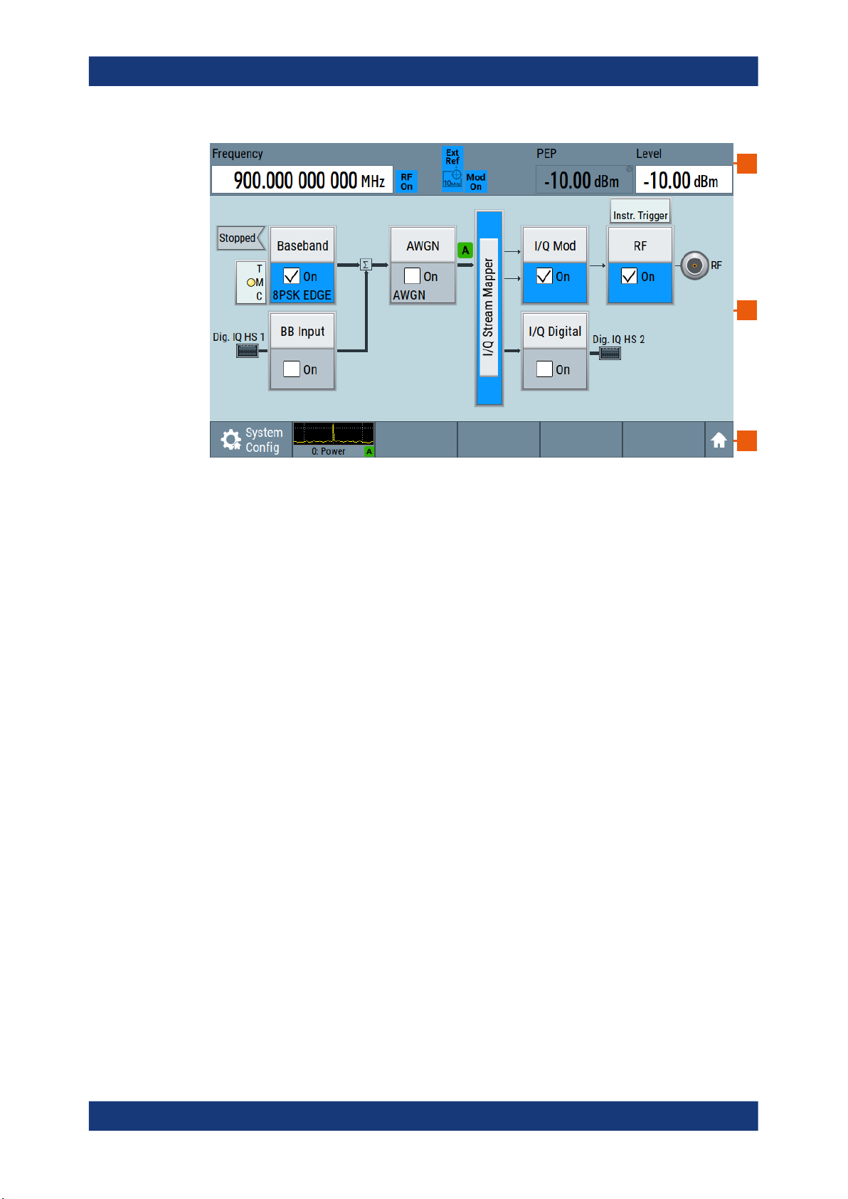
R&S®SMCV100B
Getting started
Instrument tour
1
2
3
Figure 3-4: Touchscreen elements
1 = Status bar (frequency and level display)
2 = Block diagram
3 = Taskbar/softkey bar
Any user interface elements that react to a click by a mouse pointer also react to a tap
on the screen, and vice versa. Using the touchscreen, you can perform the following
tasks (among others) by the tap of your finger:
●
●
●
●
●
See also:
●
●
3.2.1.2 Keys
On/Standby
Changing a setting
Selecting new settings
Scrolling through a list or a table of parameters
Saving or recalling settings
Opening and closing dialogs
Chapter 3.5.2, "Means of manual interaction", on page 62, for operating the
touchscreen.
Chapter 16.1, "Cleaning", on page 802, for instructions on cleaning the screen.
The [On/Standby] key switches the instrument from the standby to the ready state or
vice versa.
The LED below the [On/Standby] key indicates the instrument state, see Chap-
ter 3.1.14, "Switching on or off", on page 32.
35User Manual 1179.0597.02 ─ 04

R&S®SMCV100B
Getting started
Instrument tour
Utility keys
The utility keys cause the R&S SMCV100B to return to a defined instrument state and
provide information on the instrument and assistance.
For more information, refer to Chapter 11, "General instrument functions",
on page 430.
Table 3-2: Utility keys
Utility key Assigned functions
[Preset] Sets the instrument to a defined state
[Save/Rcl] Saves and loads instrument setting
Accesses the file manager
[Help] Displays context-sensitive help text
Function keys
Function keys provide access to most common generator settings and functions.
A detailed description of the corresponding functions is provided in the user manual.
Table 3-3: Function keys
Function key Assigned functions
[Freq/Level] Pressing once: Activates frequency entry. Pressing twice: Activates level
entry.
Toggles between frequency and level entry.
[Home] Brings the block diagram to the foreground. Active dialogs are minimized.
[RF on/off] Switches the RF output on and off. Press the key again to restore the last
active status.
Status is displayed in the "Status bar".
[★ (User)] Key with a customizable function.
Editing keys
Editing keys enable you to confirm an entry, delete individual characters, or exit the
current operation.
Table 3-4: Editing keys
Type of key Description
[Esc] key Closes all kinds of dialog boxes, if the edit mode is not active. Quits the
edit mode, if the edit mode is active. In dialog boxes that contain a "Cancel" button it activates that button.
For "Edit" dialog boxes the following mechanism is used:
●
If data entry has been started, it retains the original value and
closes the dialog box.
●
If data entry has not been started or has been completed, it closes
the dialog box.
36User Manual 1179.0597.02 ─ 04

R&S®SMCV100B
3.2.1.3 Connectors
Getting started
Instrument tour
Navigation controls
The navigation controls include a rotary knob, navigation keys, and the display keys.
They allow you to navigate within the display or within dialog boxes.
Rotary knob
The rotary knob has several functions:
●
Increments (clockwise direction) or decrements (counterclockwise direction)
numeric instrument parameters at a defined step width.
●
Moves the selection, e.g. to a function block in the block diagram.
●
Shifts the selection bar within focused areas (e.g. lists).
●
Activates editing of entries or confirms and terminates entries.
●
Opens a context-sensitive menu, when it is pressed and held.
The RF 50 Ω connector and USB connector are on the front panel.
USB
Female USB (universal serial bus) 2.0 connector of type A (host USB). You can connect, for example, a keyboard, a mouse or a USB memory stick.
Further USB connectors of type A are available on the rear panel.
How to: Chapter 3.1.9, "Connecting USB devices", on page 28.
RF 50 Ω
Output of the RF signal (N female connector).
How to: Chapter 3.1.10, "Connecting to RF 50 Ω", on page 28
3.2.2 Rear panel tour
This section provides an overview of the connectors on the rear panel of the instrument. For technical data of the connectors, refer to the data sheet.
37User Manual 1179.0597.02 ─ 04

R&S®SMCV100B
Getting started
Instrument tour
51 2 43
6789
Figure 3-5: Rear panel
1 = AC power supply connector and switch, page 38
2 = DVI-D, page 38
3 = Serial number (six digits in the string 1432.7000.02-<serial number>-<checksum>)
4 = LAN, page 38
5 = USB, page 39
6 = Dig. IQ HS x, page 39
7 = IP Data, page 39
8 = User x, page 39
9 = Ref In/Ref Out, page 40
3.2.2.1 Connectors
AC power supply connector and switch
Mains power switch for performing the following tasks:
●
Connecting the internal power supply to the power source
●
Disconnecting the internal power supply from the power source
How to: Chapter 3.1.6, "Connecting to power", on page 26.
DVI-D
DVI-D socket. Output for the monitor signal of the built-in computer. The connected
computer monitor should provide a resolution of 1024x768 pixels or higher.
How to: Chapter 3.1.8, "Connecting a monitor", on page 27
LAN
RJ-45 connector to connect the R&S SMCV100B to a LAN for remote control, remote
operation, and data transfer.
How to: Chapter 3.1.7, "Connecting to LAN", on page 26
38User Manual 1179.0597.02 ─ 04

R&S®SMCV100B
Getting started
Instrument tour
USB
Two female USB (universal serial bus) 3.0 connectors of type A (host USB). They have
the same functionality as the USB connectors on the front panel, but provide higher
data rates. See "USB" on page 37.
How to: Chapter 3.1.9, "Connecting USB devices", on page 28.
Dig. IQ HS x
Connectors for the input/output of high-speed digital I/Q signals, for example, from and
to Rohde & Schwarz instruments.
Table 3-5 lists the interface designation (input/output) and the required option.
For more information, see data sheet.
Table 3-5: Overview of Dig. IQ HS x interfaces and required options
Interface Designation Required option
Dig. IQ HS 1 "BB Input" R&S SMCVB-K19 digital baseband interface
Dig. IQ HS 2 "I/Q Digital Out"
The interface is a QSFP+ (Quad Small Form-factor Pluggable) module. It supports
max. bandwidth of up to 50 Gsample/s with optical active cables.
How to: Chapter 3.1.12, "Connecting to Dig. IQ HS x", on page 30
IP Data
Interface for input of IP data for real-time encoding in broadcast baseband signals.
The interface comprises a SFP+ (Small Form-factor Pluggable) socket.
How to: Chapter 3.1.13, "Connecting to IP Data interface", on page 31
User x
BNC multipurpose connectors for defining input signals and output signals.
Table 3-6 lists the signals assigned to the User x connectors in the default instrument
state.
Table 3-6: Default configuration of the User x connectors
User connector Direction Default assigned signal
1 Output Baseband Marker 1
2 Input Global Clock
A dedicated LED indicates the connector status:
●
green: an input connector
●
yellow: an output connector
●
red: error
●
no light / gray: the connector is not active
●
blinking LED: connection indication as a result of the "Identify Connector" func-
tion
See also Chapter 11.2, "Configuring global connectors", on page 434.
39User Manual 1179.0597.02 ─ 04

R&S®SMCV100B
3.3 Trying out the instrument
Getting started
Trying out the instrument
Ref In/Ref Out
Input/output for external reference signal.
BNC connectors for reference signals from 1 MHz to 100 MHz.
How to: Chapter 3.1.11, "Connecting to Ref In/Ref Out", on page 29
This chapter introduces the most important functions and settings of the
R&S SMCV100B step by step.
The complete description of the functionality and its usage is given in the
R&S SMCV100B user manual. Basic instrument operation is described in Chapter 3.5,
"Instrument control", on page 62.
Prerequisites
●
R&S SMCV100B equipped with its minimum configuration:
– Base unit
– Frequency option R&S SMCVB-B103
●
The R&S SMCV100B is connected to the power supply, and started up as described in Chapter 3.1, "Preparing for use", on page 23.
For the first signal generation tasks, you use the internal baseband and reference signal, so you do not need any additional signal source. More complex signal generation
tasks, however, require an instrument equipped with additional options and/or external
signals. Each task description lists its prerequisites.
The screenshots in this description show a fully equipped instrument. Consider that,
the block diagram displayed on your particular instrument can differ from the one used
in the example.
Touchscreen operation
For detailed information on touchscreen operation, see Chapter 3.5.2, "Means of man-
ual interaction", on page 62.
The following sections provide introductory operation examples using the touchscreen.
● Generating an unmodulated carrier........................................................................ 41
● Generating a digitally modulated signal.................................................................. 42
● Triggering the instrument with an external signal....................................................45
● Enabling and configuring a marker signal...............................................................49
● Verifying the generated signal with the graphics display........................................ 51
● Saving and recalling settings.................................................................................. 54
● Generating a DAB signal.........................................................................................56
40User Manual 1179.0597.02 ─ 04

R&S®SMCV100B
3.3.1 Generating an unmodulated carrier
Getting started
Trying out the instrument
We start out by generating a simple unmodulated signal. The R&S SMCV100B has a
minimum configuration as in "Prerequisites" on page 40.
1. On the R&S SMCV100B front panel, press the Preset key to start out in a defined
instrument configuration.
2. Set the frequency:
a) On the "Status Bar", tap the "Frequency" field.
b) On the on-screen keypad, enter 1.955 and press the "GHz" key.
The on-screen keypad closes and the frequency value is displayed.
3. On the "Status Bar", tap the "Level" field and enter the level in the same way.
4. Select "Block Diagram > RF Block > On" to enable the output of the generated
unmodulated signal.
41User Manual 1179.0597.02 ─ 04

R&S®SMCV100B
Getting started
Trying out the instrument
Figure 3-6: Block diagram: Generating an unmodulated signal
The 1.955 GHz signal is output at the RF 50 Ω connector at the front panel of the
R&S SMCV100B.
Connect RF 50 Ω of the R&S SMCV100B to a signal analyzer, for example R&S®FSW,
to display the generated signal.
Figure 3-7: Simplified test setup
For the required settings of the signal analyzer, refer to its user manual or its online
help.
3.3.2 Generating a digitally modulated signal
This example shows you how to generate a simple WCDMA-3GPP (QPSK 45° offset)
signal with the help of the "Custom Digital Modulation" functionality.
42User Manual 1179.0597.02 ─ 04
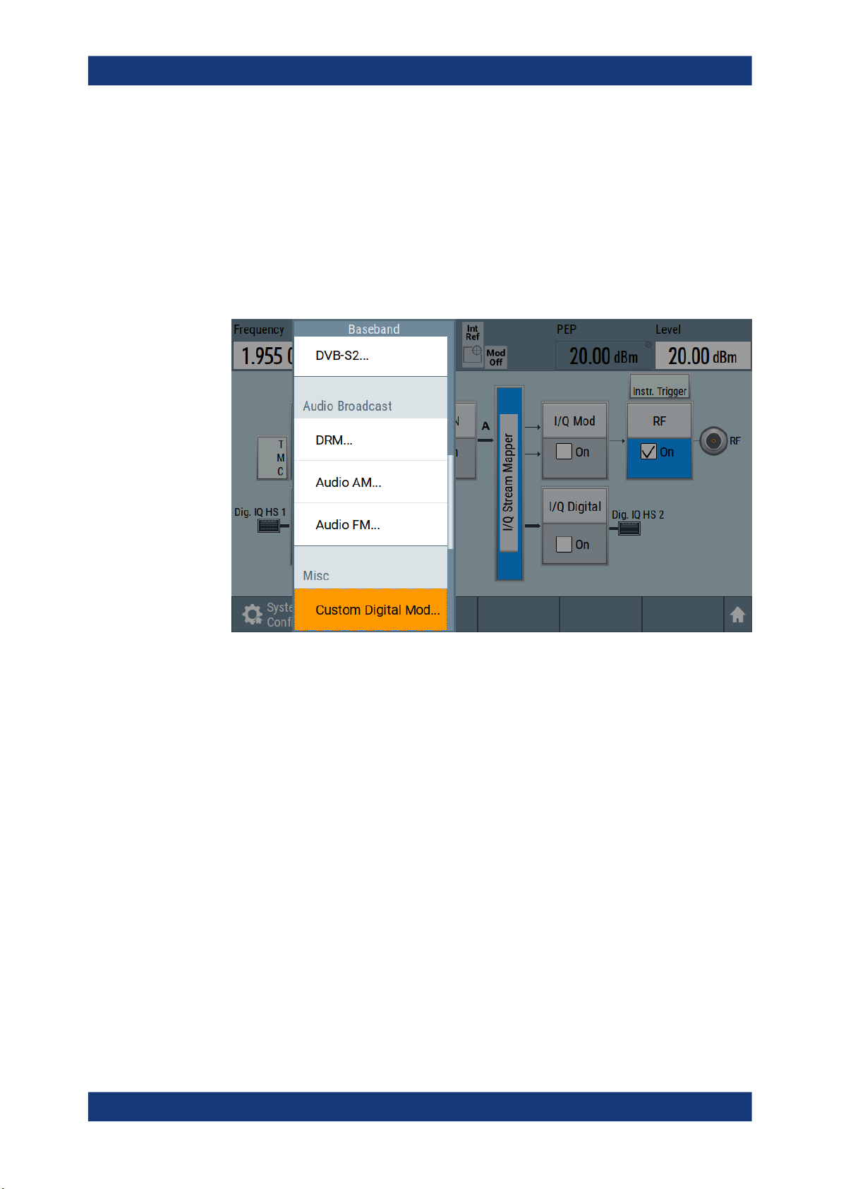
R&S®SMCV100B
Getting started
Trying out the instrument
Prerequisites
●
Minimum configuration as in "Prerequisites" on page 40
●
Option custom digital modulation R&S SMCVB-K199
The initial situation is not the instrument's preset state but rather the configuration
described in Chapter 3.3.1, "Generating an unmodulated carrier", on page 41.
1. In the block diagram, select "Baseband" and navigate to the section "Misc > Custom Digital Mod...".
The "Custom Digital Modulation" dialog opens.
2. In the "Custom Digital Modulation" dialog, select "General > Set according to Standard > WCDMA-3GPP".
3. Select "General > State > On" to enable signal generation.
43User Manual 1179.0597.02 ─ 04
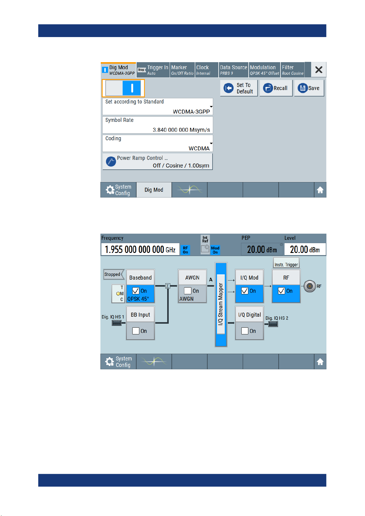
R&S®SMCV100B
Getting started
Trying out the instrument
The instrument activates automatically "I/Q Mod", uses the internal trigger and
clock signals, and generates a WCDMA-3GPP signal, modulated with a QPSK 45°
offset modulation.
Figure 3-8: Block diagram: Generating a digitally modulated signal
4. Optionally, select the "Modulation" tab and observe the used "Modulation Type".
44User Manual 1179.0597.02 ─ 04
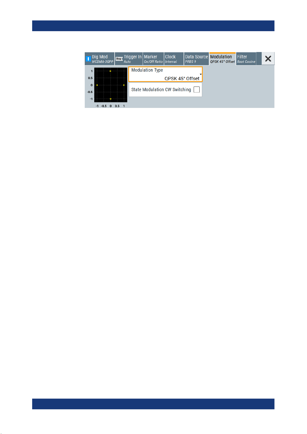
R&S®SMCV100B
3.3.3 Triggering the instrument with an external signal
Getting started
Trying out the instrument
Figure 3-9: Display of the used modulation type
The following configurations are rather theoretical cases, because you rarely use the
R&S SMCV100B as a standalone instrument. Usually, the instrument would be connected to a device under test (DUT) and/or other measurement equipment.
Prerequisites
●
Minimum configuration as in "Prerequisites" on page 40
●
Option custom digital modulation R&S SMCVB-K199
As a rule, whenever a test setup requires two or more devices, provide them with a
common reference frequency. Some test setups require control of the signal generation start and an exact generation start time, determined by a defined trigger event. For
example, by triggering the instrument internally or externally from the DUT.
The example below illustrates the general principle of external triggering and extends
the configuration performed in Chapter 3.3.2, "Generating a digitally modulated signal",
on page 42 by the configuration of the required trigger signal and connector settings.
This test setup requires one signal analyzer, like the R&S®FSW, as additional equipment.
To start signal generation synchronous to an external global trigger signal
The configuration requires three main steps with the following goals:
1. Observe the current connector configuration. Define an input connector for the
external global trigger signal.
See "To verify the current connector configuration" on page 46
2. Configure the baseband to use the external global trigger signal as trigger source.
See "To reconfigure the trigger settings" on page 47
3. Connect the instrument and the external trigger source.
See "To connect the instrument and the external trigger source" on page 48
45User Manual 1179.0597.02 ─ 04

R&S®SMCV100B
Getting started
Trying out the instrument
To verify the current connector configuration
The R&S SMCV100B is equipped with multipurpose bi-directional User connectors.
Because the signal direction, input or output, and the signal mapping are configurable,
we recommend that you check the current configuration before cabling or further
instrument's configurations.
1. To display an overview of the current mapping of the logical signals to the connectors, perform one of the following:
● In the block diagram, select the Trigger/Marker/Clock status LEDs on the left
side of the "Baseband" block.
● Select "Baseband > Trigger Marker Clock".
The instrument uses its internal trigger and clock signals, and the default mapping
of the marker signals to the User connectors.
2. To access the related connector settings, perform one of the following:
● Select "Global Connector Settings"
● Tap the connector name, for example select the connector "User 1"
Figure 3-10: Signal mapping to the global connectors
46User Manual 1179.0597.02 ─ 04

R&S®SMCV100B
Getting started
Trying out the instrument
The "Global Connectors" dialog displays the current connectors configuration. The
settings are configurable, but in this example we use the default mapping.
3. Alternatively, select "Block Diagram > Baseband > Misc > Custom Digital Mod",
select the "Trigger In" tab and select "Global Connector Settings".
In the current mapping, the two global connectors User x on the rear panel are
configured as follows:
● "Baseband Marker" signal is output at the "User 1" connector.
The LED next to the connector is
● The "User 2" connector is an input for the "Global Trigger" signal.
The LED next to the connector is green.
Find the physical location of each connector
Use the built-in "Trigger Marker Clock > Show " function to display the location of the
selected connector. A blinking marker on the front/rear panel view also indicates the
selected connector.
To reconfigure the trigger settings
orange.
We assume that the instrument is configured as described in Chapter 3.3.2, "Generat-
ing a digitally modulated signal", on page 42 and the default connector mapping is
maintained (see Figure 3-10).
1. In the block diagram, select "Baseband > Misc > Custom Digital Mod > Trigger In".
2. Select the following settings:
a) "Mode > Armed Auto"
b) "Source > External Global Trigger".
3. Select "Global Connector Settings > Routing".
4. For "User 2", select "Direction > Input" and "Signal > Global Trigger".
47User Manual 1179.0597.02 ─ 04
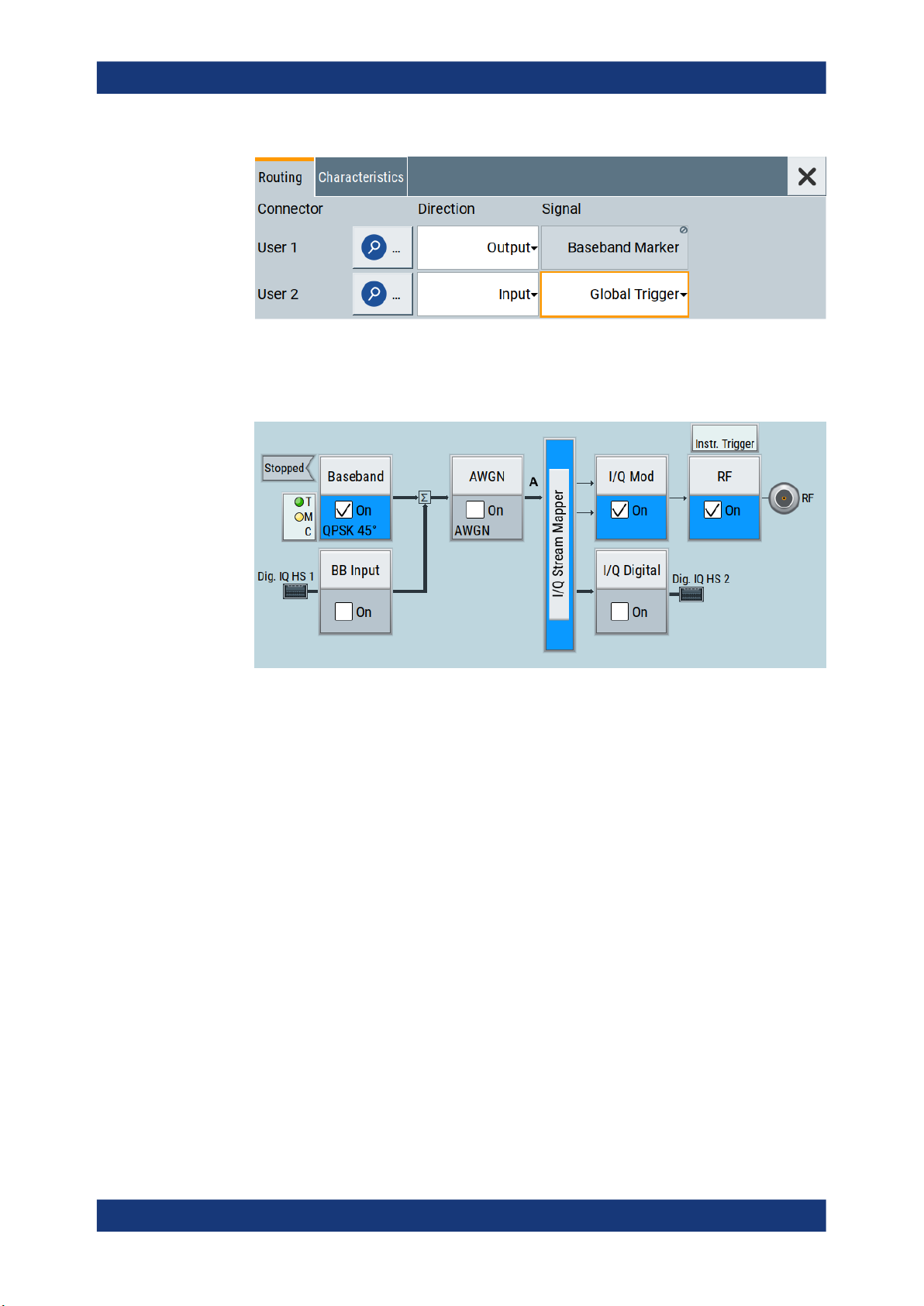
R&S®SMCV100B
Getting started
Trying out the instrument
The instrument expects an external global trigger event. In the current configuration, the "Global Trigger" signal has to be supplied at the input connector User 2.
The Trigger/Marker/Clock status LEDs in the block diagram confirm that an external trigger signal is selected; the signal generation is however stopped.
To connect the instrument and the external trigger source
1. Use a suitable cable to connect the external trigger source to the User 2 connector
of the R&S SMCV100B. See Figure 3-11.
48User Manual 1179.0597.02 ─ 04

R&S®SMCV100B
Getting started
Trying out the instrument
Figure 3-11: Simplified representation of a test setup**
** = The figure depicts the cabling as a general principle; particular test setups do not require all con-
nections at the same time
The Figure 3-11 depicts the location of the connectors and explains the connection
as principle. In practice, you would rather "substitute" the analyzer by a DUT, like a
base station (BS).
Other than in the example, the DUT can be the source for the reference signal.
Instead of using an external trigger source, the DUT can also send, for example, a
frame trigger signal to the R&S SMCV100B. The R&S SMCV100B acts still as the
signal source.
2. Use suitable cables to connect to RF 50 Ω and Ref. In connectors of the
R&S SMCV100B to the signal analyzer or the DUT.
The R&S®FSW supplies the 10 MHz external reference signal.
Upon the receiving of an external trigger event, the R&S SMCV100B starts the signal generation and then generates a continuous signal. An "Arm" stops the signal
generation. A subsequent trigger event causes a restart of the signal generation.
To learn more about this topic, refer to:
●
Chapter 4.4.1.3, "Baseband trigger signals", on page 84
3.3.4 Enabling and configuring a marker signal
Test setups often require synchronization of an external device with the generated data
stream. For this purpose, the R&S SMCV100B can output maximum two marker signals (or markers) also to the generated signal.
The R&S SMCV100B provides four regular marker signals. You can output two of the
marker signals, one to each of the "User 1"/"User 2" connectors.
49User Manual 1179.0597.02 ─ 04

R&S®SMCV100B
Getting started
Trying out the instrument
With suitable marker settings for instance, you can mark slot or frame boundaries or
mark the start of a particular modulation symbol.
Prerequisites
●
Minimum configuration as in "Prerequisites" on page 40
●
Option custom digital modulation R&S SMCVB-K199
This example extends further the configurations performed in Chapter 3.3.2, "Generat-
ing a digitally modulated signal", on page 42. We assume a default connector mapping
(see Figure 3-10).
This test setup requires one oscilloscope, like the R&S®RTO, as additional equipment.
1. In the block diagram, select "Block Diagram > Baseband > Misc > Custom Digital
Mod > Marker" tab.
2. Select "Marker Mode > Marker 1 > Pulse" and "Divider = 32".
Generated is a periodic marker with marker frequency of 120 KHz. The signal is
output at the User 1 connector of the R&S SMCV100B (see Figure 3-10).
3. Use a suitable cable to connect the User 1 connector of the R&S SMCV100B to
the monitoring instrument, for example an oscilloscope like R&S®RTO. See Fig-
ure 3-12.
Figure 3-12: Simplified representation of a test setup for signal monitoring**
** = The figure depicts the cabling as a general principle
4. Use a suitable cable to connect the "RF 50 Ω" on page 37 connector of the
R&S SMCV100B to the monitoring instrument.
50User Manual 1179.0597.02 ─ 04

R&S®SMCV100B
3.3.5 Verifying the generated signal with the graphics display
Getting started
Trying out the instrument
To learn more about this topic, refer to Chapter 4.4.1.2, "Regular marker output sig-
nals", on page 82.
It is often useful to check the spectra of the configured signals, before you enable the
RF output of the instrument. The R&S SMCV100B has a minimum configuration as in
"Prerequisites" on page 40
The R&S SMCV100B provides a build-in function to represent the generated signal on
a graphical signal display. We demonstrate this feature by showing the characteristics
at one particular point of the signal processing chain. You can, however, display the
signal characteristics at other different stages.
This example shows you how to use this graphical display to verify the generated signal. Use the signal generated in Chapter 3.3.4, "Enabling and configuring a marker sig-
nal", on page 49.
To access the graphical signal display functionality
► Perform one of the following:
● Select "Taskbar > System Configuration > Graphics".
● On the "Taskbar", tap the wave icon.
The "Graphics Configuration" dialog opens.
To visualize the signal
1. In the "Graphics Configuration" dialog, select "Mode > Constellation".
51User Manual 1179.0597.02 ─ 04

R&S®SMCV100B
Getting started
Trying out the instrument
2. Select "Source > Baseband".
3. Select "Add" to enable signal display.
In the "Summary" tab, you can verify, that "Channel 0" graphic is visible in the
table:
A new thumbnail (minimized view) indicating the active diagram appears in the
"Taskbar".
4. Press the thumbnail graphic.
The graphic enlarges and the diagram is displayed in a normal size.
52User Manual 1179.0597.02 ─ 04

R&S®SMCV100B
Getting started
Trying out the instrument
The "Constellation Diagram" displays the 3GPP FDD signal.
5. To retrieve more information, zoom in. In some diagrams you can select "Show
Marker" to measure the distance, for example, between two signals.
In principle, the zoom in function works like the two-finger pinching for magnifying
images on your cellphone.
6. In the "Constellation Diagram" dialog, select "Configure" to return to the "Graphics
Configuration" dialog.
Close the "Graphics Configuration" dialog.
This action has no effect on the configured graphics but on the dialog itself.
The block diagram displays the current signal routing. It indicates that frequency
and power offsets are enabled and displays the acquisition points for the real-time
diagrams minimized in the "Taskbar".
53User Manual 1179.0597.02 ─ 04

R&S®SMCV100B
3.3.6 Saving and recalling settings
Getting started
Trying out the instrument
See also Chapter 9, "Monitoring signal characteristics", on page 380.
To restore the results of our measurements later, we save the instrument settings to a
file.
To save the instrument settings to a file
We assume, a test configuration as described in Chapter 3.3.4, "Enabling and configur-
ing a marker signal", on page 49.
1. Press the [Save/Rcl] key on the front panel.
2. In the "Save/Recall" dialog box, select "Operation Mode > Save".
Tap the "Filename", use the on-screen keyboard, and enter MyTestSignal.
3. Tap the "Save" button.
The file MyTestSignal.savrcltxt is saved in the default directory /var/user.
To load saved instrument settings
You can restore the settings to the instrument at any time using the settings file.
1. Press the Preset button to restore the default instrument settings.
2. Press the Save/Rcl key.
3. In the "Save/Recall" dialog, select "Recall" operation.
Navigate to the directory of the saved file. Select the MyTestSignal file.
54User Manual 1179.0597.02 ─ 04

R&S®SMCV100B
Getting started
Trying out the instrument
4. Tap the "Recall" button.
All instrument settings are restored and the display resembles the instrument display right before the settings were saved.
To display all parameters with values different to their preset values
After loading saved instrument setting, visualize all parameters that have been
changed from their default state.
1. In the block diagram, open the context-sensitive menu:
a) Imitate a right-click.
b) Tap and hold on an empty space in the block diagram for about one second.
2. In the context-sensitive menu, select "Mark All Parameters Changed from Preset".
All changed parameters are highlighted.
55User Manual 1179.0597.02 ─ 04
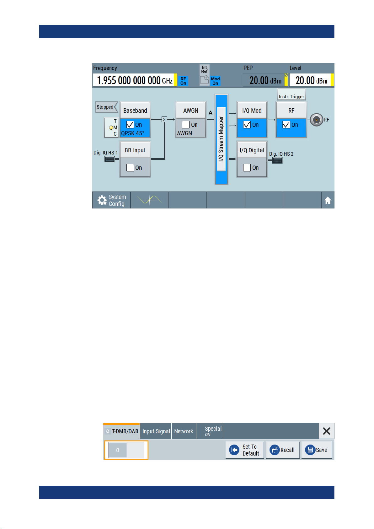
R&S®SMCV100B
Getting started
Trying out the instrument
See also Chapter 10, "File and data management", on page 399.
3.3.7 Generating a DAB signal
The main application field of the R&S SMCV100B is the generation of digital signals in
accordance with broadcast standards, like DAB, DVB-T2 or ATSC3.0, to name a few.
This example uses the digital broadcast standard DAB.
You can access and interact with the instrument and experience the advantages provided by the additional options.
Prerequisites
●
Minimum configuration as in "Prerequisites" on page 40
●
Option "Enable broadcast standard" R&S SMCVB-K519
●
Option DAB/T-DMB R&S SMCVB-K156
To generate a DAB test signal
1. On the R&S SMCV100B front panel, press the Preset key to start out in a defined
instrument configuration.
2. In the block diagram, select "Baseband > T-DMB/DAB".
The "T-DMB/DAB" dialog appears and displays the general settings provided for
the digital standard.
56User Manual 1179.0597.02 ─ 04

R&S®SMCV100B
Getting started
Trying out the instrument
As in the user interfaces of all broadcast standards, the "T-DMB/DAB" dialog is
divided into several tabs. The "T-DMB/DAB" tab comprises the primary settings of
the standard.
Also, the functions for storing and recalling settings and provides access to further
functions and dialogs. The more complex the digital standard itself is, the more
comprehensive the further dialog and tab structure.
3. In the "Input Signal" tab, select "Source > Test Signal".
The test signal is a signal with audio content.
Tip: On the front panel, press the Help key to retrieve detailed information on the
current settings and on the contents of the predefined files.
4. In the "T-DMB/DAB" tab, select "State > On".
5. On the "Status Bar", set "Frequency" and "Level" of the DAB test signal:
a) Tap the "Frequency" field, to enter the center frequency, for example
174.928
b) Tap the "Level" field, to enter the RMS level, for example 20.00 dBm.
MHz.
57User Manual 1179.0597.02 ─ 04

R&S®SMCV100B
Getting started
System overview
6. On the "Status Bar", activate the RF output: Set "RF On > RF On".
The instrument generates a DAB test signal with the set frequency, and level.
With these first steps, you have gained an impression of the provided functionality.
For a comprehensive description of the full range of capabilities, refer to the user man-
ual "DAB Digital Standard for R&S SMCV100B".
3.4 System overview
This section helps you to get familiar with the R&S SMCV100B. It provides an introduction to the general concept of the instrument. This section also introduces the main
blocks in the signal generation flow.
For information on how to access functions and interact with the R&S SMCV100B,
refer to Chapter 3.5, "Instrument control", on page 62.
3.4.1 Brief introduction to the instrument's concept
The R&S SMCV100B offers excellent RF and baseband characteristics. The baseband
section of the R&S SMCV100B is fully digital. It contains the hardware for generating
and processing I/Q signals in realtime or generating signals with an arbitrary waveform
generator.
58User Manual 1179.0597.02 ─ 04
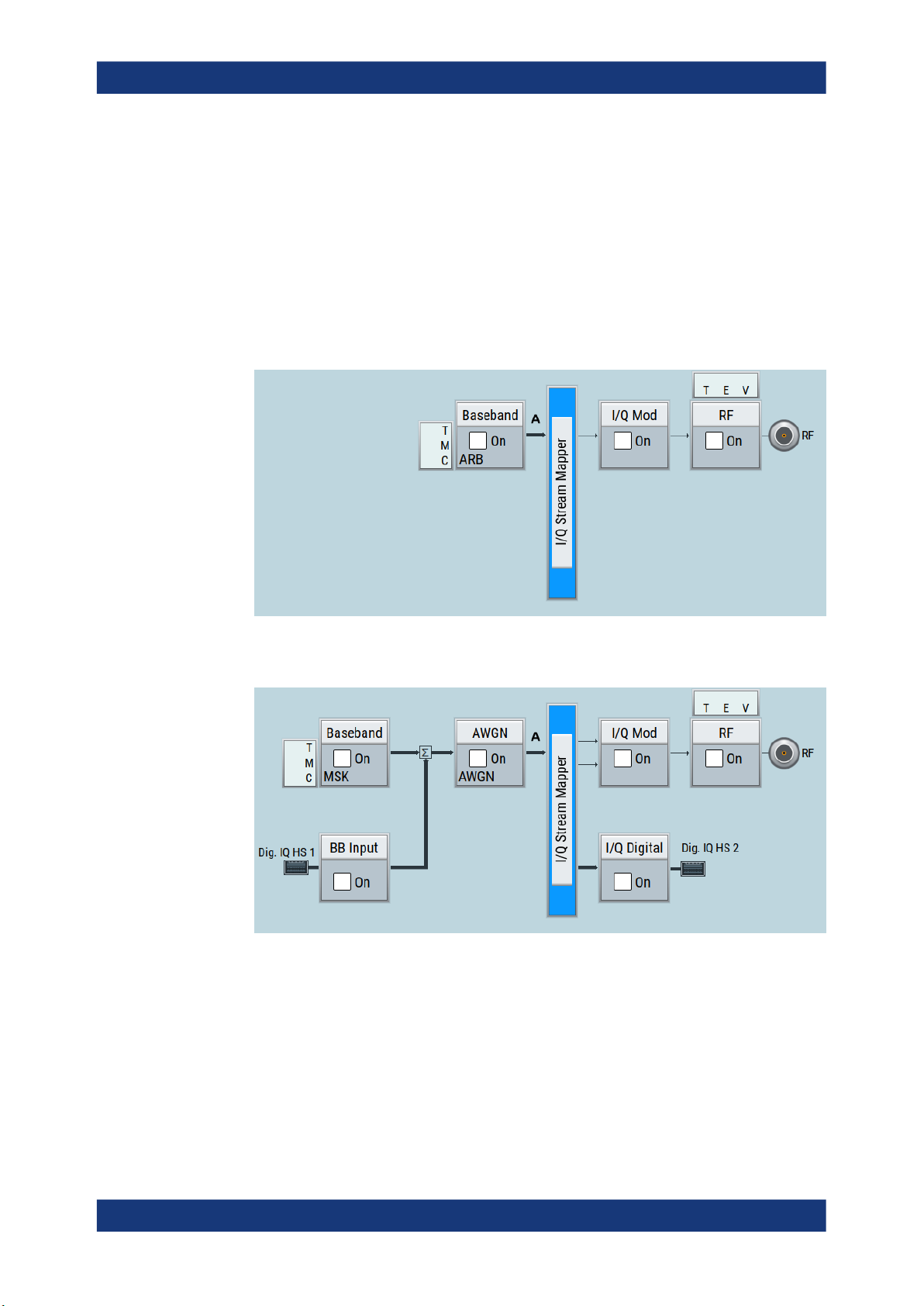
R&S®SMCV100B
3.4.2 Signal flow at a glance
Getting started
System overview
The R&S SMCV100B is equipped with a large touchscreen, that displays a block diagram. The block diagram represents the signal flow and the general stages the signal
generation goes through. Depending on the options the R&S SMCV100B is equipped
with, the appearance of the block diagram changes.
The following examples do not cover all possible cases but aim to introduce the way
the block diagram depicts the installed options.
●
Minimum configuration example of a base unit and frequency option R&S SMCVBB103.
●
An example of a fully equipped instrument.
The block diagram displays all blocks for installed software options. Arrows within
the block diagram indicate the signal flow.
The cross-reference between the installed options and the displayed settings
The Table 3-7 is an excerpt of the available options and lists only the options required
to display a functional block in the block diagram. The information assumes
R&S SMCV100B minimum configuration comprising base unit and frequency option
R&S SMCVB-B103.
For exact information on the available options, and on the minimum requirements and
the interdependencies between the provided options, refer to the R&S SMCV100B
data sheet.
59User Manual 1179.0597.02 ─ 04
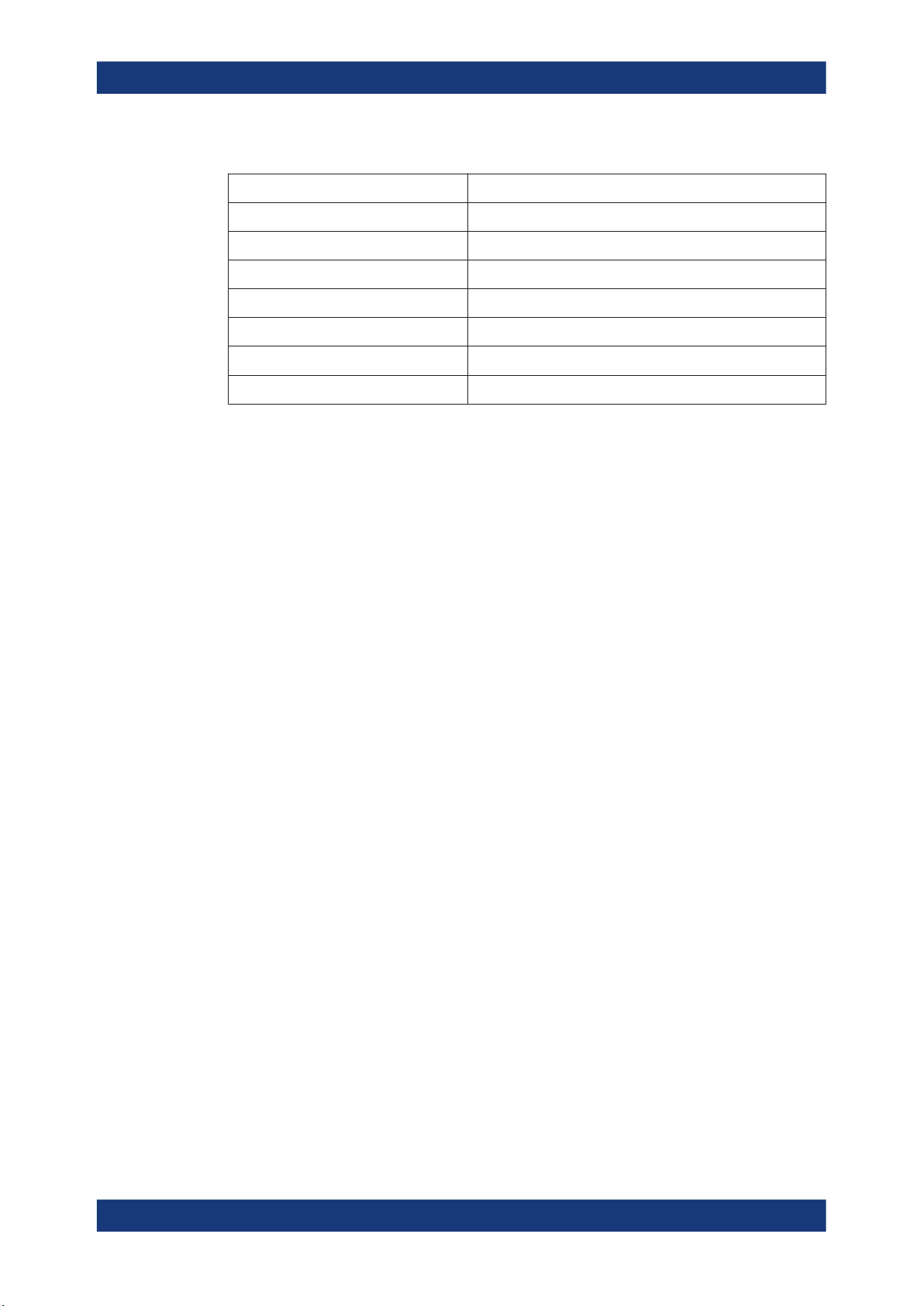
R&S®SMCV100B
3.4.3 Internal baseband source ("Baseband" block)
Getting started
System overview
Table 3-7: Required options per functional block (excerpt)
Functional block Required option
"Baseband" -
"BB Input" R&S SMCVB-K19
"AWGN" R&S SMCVB-K62
"I/Q Stream Mapper" -
"I/Q Mod" -
"I/Q Digital" R&S SMCVB-K19
"RF" -
The "Baseband" block represents the source of the baseband signals (basebands).
This functional block is the access point to:
●
The internal baseband generator
The baseband generator contains modules for real-time signal generation ("Custom Digital Modulation" requires R&S SMCVB-K199) and an arbitrary waveform
generator (ARB).
●
The available digital standards
Generation of digital signals in accordance with the supported standards requires
additional software options. For example, option R&S SMCVB-K162 generates signals according to the ATSC 3.0 standard.
●
The baseband offsets function
Signals from the baseband generator can be shifted in frequency and phase.
3.4.4 Digital baseband input/output ("BB input"/ "I/Q digital" block)
The "BB Input" and the "I/Q Digital" blocks are the access point to the settings of the
digital interfaces Dig. IQ HS x.
Equipped with option R&S SMCVB-K19, the R&S SMCV100B is able to receive digital
baseband signals and to output digital baseband signals. You can use both interfaces
in parallel: Dig. IQ HS 1 is input and Dig. IQ HS 2 is output of the digital baseband signals.
The digital baseband inputs and outputs can be used together with other
Rohde & Schwarz instruments, like signal generators. A Rohde & Schwarz signal generator for instance can serve as digital signal source in test configuration requiring two
baseband sources.
The "BB Input" block is the access point to the settings of:
●
The external digital I/Q signals
The external digital I/Q signals are further processed in the baseband section.
●
The baseband offsets function
60User Manual 1179.0597.02 ─ 04

R&S®SMCV100B
3.4.5 Additional white gaussian noise ("AWGN" block)
3.4.6 "I/Q stream mapper" block
Getting started
System overview
The external and internal baseband signals can be shifted in frequency and phase.
The "I/Q Digital" block is the access point to the settings of the digital I/Q output signals.
The "AWGN" block is displayed only in instruments equipped with the option
R&S SMCVB-K62. This block controls the additional white Gaussian noise generator
(AWGN). An additive white noise is required for measurements of mobile radio base
stations.
As one of the access points to the system configuration settings, the "I/Q Stream Mapper" provides direct access for mapping the generated I/Q streams to the available output connectors. That is, to the RF 50 Ω output connector and to the Dig. IQ HS 2 output connectors.
3.4.7 I/Q modulator ("I/Q mod" block)
The "I/Q Mod" block represents the I/Q modulator.
This functional block is the access point to:
●
The I/Q modulation of the internal baseband signal
●
The digital I/Q impairments
3.4.8 RF ("RF" block)
The "RF" block represents the RF settings of the instrument.
This block is the access point to:
●
RF frequency and level settings, and the reference frequency, user correction, etc.
●
The list and sweep modes
3.4.9 Applications examples of the R&S SMCV100B
The R&S SMCV100B can be optimally adapted to the requirements of different applications:
●
Generation of digitally modulated signals using
– The internal baseband generator
– The externally applied digital baseband signals
●
Generation of wanted signals or interfering signals for receiver tests
61User Manual 1179.0597.02 ─ 04

R&S®SMCV100B
3.5 Instrument control
Getting started
Instrument control
●
Generation of signals with up to 240 MHz signal bandwidth (R&S SMCVB-K523)
This chapter provides an overview on how to work with the R&S SMCV100B.
It covers the following topics:
● Possible ways to operate the instrument................................................................ 62
● Means of manual interaction...................................................................................62
● Understanding the display information....................................................................63
● Accessing the functionality......................................................................................68
● Entering data...........................................................................................................69
● Getting information and help...................................................................................70
● Remote control........................................................................................................72
● Remote operation over VNC...................................................................................72
3.5.1 Possible ways to operate the instrument
There are three ways to operate the R&S SMCV100B:
●
Manual operation:
Use the touchscreen, hard keys and rotary knob, or an optional mouse and/or keyboard.
The description under Chapter 3.5, "Instrument control", on page 62 shows how to
operate the instrument manually.
●
Remote control:
Create programs to automatize repeating settings, tests and measurements. The
instrument is connected to a computer running the program.
This way of operation is described in Chapter 12, "Network operation and remote
control", on page 476.
●
Remote operation from a computer:
Remote monitoring and control of the instrument from a connected computer is
based on the common cross-platform technology VNC (Virtual Network Computing). On the remote computer, any standard web browser (supporting Java) or a
dedicated VNC client (like Ultr@VNC) can be used. See also Chapter 3.5.8,
"Remote operation over VNC", on page 72.
3.5.2 Means of manual interaction
For the manual interaction with the R&S SMCV100B, you have several methods that
you can use as an alternative to perform a task:
●
Touchscreen:
Touchscreen operation is the most direct way to interact. Almost all control elements and actions on the screen are based on the standard operating system concept. You can tap any user interface element to set parameters in dialog boxes,
enter data, scroll within a dialog etc., as if you work with a mouse pointer.
62User Manual 1179.0597.02 ─ 04

R&S®SMCV100B
Getting started
Instrument control
Tapping the screen works like clicking mouse buttons:
– Touch quickly = click: Selects a parameter or provokes an action.
– Touch and hold = right-click: Opens a context-sensitive menu.
– Touch and swipe = drag: Scrolls through the contents of a display element
larger than the screen, e.g. a list or a table.
●
Function keys and rotary knob:
The front panel provides nearly all functions and controls to operate the instrument
in the classic way, without touchscreen.
●
Optional mouse and/or keyboard:
These devices work like known from PCs. The navigation keys on the front panel
correspond to the keys on the keyboard.
This manual describes the manual interaction with the instrument via the touchscreen.
It mentions the alternative methods using the keys on the instrument or the on-screen
keypads if it deviates from the standard operating procedures. The usage of the touchscreen and navigation keys is described in Chapter 3.5.4, "Accessing the functionality",
on page 68.
Throughout the manual, the term "select" refers to any of the following methods:
●
Using a finger on the touchscreen
●
Using a mouse pointer in the display
●
Using a key on the instrument or on a keyboard
3.5.3 Understanding the display information
The block diagram of the R&S SMCV100B displays all main settings and generator
states, divided into three main operation areas.
Figure 3-13: Block diagram
1
2
3
63User Manual 1179.0597.02 ─ 04

R&S®SMCV100B
3.5.3.1 Status bar
Getting started
Instrument control
1 = Status bar (frequency and level display)
2 = Block diagram
3 = Taskbar/softkey bar
● Status bar................................................................................................................64
● Block diagram......................................................................................................... 64
● Taskbar....................................................................................................................65
● Additional display characteristics............................................................................ 66
The status bar at the top of the screen indicates the RF frequency and the level of the
output signal provided to the DUT. You can set both parameters directly here.
1 2 3
1
= Frequency display
2 = Status buttons
3 = Level display
The status buttons indicate key parameters that are set for the output signal. Most of
the status buttons are virtual keys you can use to open a corresponding menu or dialog.
3.5.3.2 Block diagram
The block diagram shows the current configuration and the signal flow in the generator
with the aid of function blocks, connected by signal lines. The following figure displays
the most common elements that can appear in the block diagram. However, it does not
necessarily represent a useful configuration.
3 4 5 6 8 97
2
10
1
Baseband domain, digital RF domain, analog
11
64User Manual 1179.0597.02 ─ 04

R&S®SMCV100B
Getting started
Instrument control
1, 10, 11 = Connector icons (digital, RF)
2, 9 = Control signal block
3 = Status indicator
4 = Functional block
5, 6 = Graphics indicator
7 = Signal line (digital)
8 = Signal line (analog)
Starting from left up to the "I/Q Mod" functional block, you can see the functional blocks
provided in the baseband domain. After the I/Q modulation on the analog RF carrier,
the analog section implies the routing to the "RF" functional block.
Legend Item Description
1, 10, 11 Connector icon Represents the interfaces for signal input and output.
2, 9 Control signal block Indicates information on the control signals like signal content, input or
3 Status indicator Indicates whether the signal is running or waiting for a trigger.
4 Functional block Represents a basic task in signal generation.
5, 6 Graphics indicator
7, 8
3.5.3.3 Taskbar
Signal line
●
digital
●
analog
●
Digital I/Q HS signal connector input and output (1, 11)
●
RF signal connector output (10)
Icons vary depending on the frequency.
output and provides quick access to the corresponding configuration
dialog.
A dedicated control block is displayed to the left of the baseband block
(2) and above the RF block (9).
The push button provides access to any number of associated actions to
accomplish the task.
The On/Off (checkbox) and the block label quickly activates the basic
task.
Denotes that the signal is displayed graphically:
●
Baseband signal after the baseband block (5)
●
Stream signal before mapping (6)
Shows the currently configured signal flow:
●
Thick lines represent digital I/Q streams (7).
●
Thin lines represent analog signals (8).
The "Taskbar" contains labeled softkeys and minimized views (thumbnails) of active
graphics and dialogs.
Initially, it shows the permanently assigned softkeys. The softkey with the sine wave
denotes that no signal is activated for graphical representation.
Figure 3-14: Taskbar in default state
Whenever you open a settings or graphics dialog, it is automatically assigned to the
"Taskbar". The softkeys shown in the following figure represent the variants.
65User Manual 1179.0597.02 ─ 04

R&S®SMCV100B
Getting started
Instrument control
1
Figure 3-15: Taskbar fully assigned
1 = System configuration
2 = Graphics
3 = Remote control connections
4 = Dialogs
5 = Diagram / more
1 System Config Provides access to general system configurations like
2 Graphics Shows that a signal is represented graphically.
3 Remote Shows the established remote connections when the
4 Dialogs Shows a dialog as a thumbnail, the dialog name, and the
5 Diagram / more The diagram icon as shown in Figure 3-14 minimizes all
2
setup, display, or remote.
instrument is remotely controlled.
Tip: An indicator in the status bar shows the current
remote control status.
name of signal channel.
dialogs indicated on the screen. The block diagram is in
the foreground.
The "More" softkey indicates that more dialogs are open
than can be displayed in the taskbar. Use this softkey to
open a selection list with the remaining active dialogs, and
the "Diagram" function.
3 54
3.5.3.4 Additional display characteristics
The following section provides a short insight on the indication of the screen in general,
and significant elements that you see under specific operating modes, in dialogs or settings.
●
Appearance of active elements
– Active elements like On/Off switches, state buttons have a blue background.
– Selected elements are framed or highlighted orange.
– Inactive elements are gray.
●
On-Screen keypads
As additional means of interacting with the instrument without having to connect an
external keyboard, either a numerical or alphanumerical on-screen keypad appears
when you activate an entry field (see Chapter 3.5.5, "Entering data", on page 69).
●
Info line
The "Info line" shows brief status information and error messages. It appears when
an event generates a message. If selected, the R&S SMCV100B shows information on static errors and the error history.
66User Manual 1179.0597.02 ─ 04

R&S®SMCV100B
Getting started
Instrument control
●
Key parameters indicated in tab labels
Most dialogs are divided into tabs with logically grouped parameters. The tab label
expresses the content and can also contain status indicators or the set value of a
key parameter.
1 1
2 2 2 2
1
= Status indicators
2 = Key parameter values
●
Scroll bar handle
An arrow icon that appears when you touch a scroll bar helps you to scroll in a dialog or list.
●
Progress indicators
A busy icon indicates a currently running process. If a process takes some time, a
progress bar shows the current state.
●
Context-sensitive menus
Within the entire screen display, including single parameters, you can access context-sensitive menus that provide some additional functions.
67User Manual 1179.0597.02 ─ 04

R&S®SMCV100B
3.5.4 Accessing the functionality
Getting started
Instrument control
All functionalities are provided in dialog boxes as known from computer programs. You
can control the instrument intuitively with the touchscreen. This section provides an
overview of the accessing methods.
The instrument's functions and settings can be accessed by selecting one of the following elements:
●
System and function keys on the front panel of the instrument
●
Taskbar/softkeys on the touchscreen
●
Context-sensitive menus for specific elements on the touchscreen, or with the
rotary knob (press and hold).
●
Elements on the status bar in the touchscreen
●
Displayed setting on the touchscreen, that means block diagram and all settings
available in dialogs.
To open a dialog box
► Perform one of the following actions:
● Tap the required block, and then the menu entry.
● Tap the minimized view (thumbnail) on the taskbar.
Some of the utility keys access a dedicated dialog, too.
To minimize a dialog box
► To return to the block diagram, tap the "Home" button.
To close a dialog box
To close a dialog box, you have the same controls as you know from computers or
devices with touchscreen.
► Perform one of the following actions:
● Tap the "Close" icon in the upper right corner.
● Press the [Esc] key on the front panel.
● Drag and drop a minimized dialog from the taskbar to the block diagram.
To select an option in a dialog box
► Tap the required option.
To select an option in a list
If many options are available - for example, for the trigger mode - the options are provided in a list. The current selection is shown on the list button.
1. Tap in the list.
2. To navigate through the list, try out the following:
● Using a mouse, scroll in the list, tap the required option.
68User Manual 1179.0597.02 ─ 04

R&S®SMCV100B
3.5.5 Entering data
Getting started
Instrument control
● Use the rotary knob.
Some parameters have their own key on the front panel.
For data input in dialog boxes, the instrument provides on-screen keypads for entering
numeric and alphanumeric values. Thus, you can always set the parameters via the
touchscreen, the front panel, or an external keyboard.
To correct an entry
1. Using the arrow keys, move the cursor to the right of the entry you want to delete.
2. On the on-screen keyboard, press "Clear".
3. Enter your correction.
To complete the entry
►
On the on-screen keyboard, press "Enter" .
To abort the entry
► Press the [Esc] key.
The dialog box closes without changing the settings.
3.5.5.1 Entering numeric parameters
To enter values with the on-screen keypad
For numeric settings, the instrument displays the numeric keypad. The units specified
correspond to the units of the parameter.
1. Enter the numeric value.
Tip: For quick entry, you can enter a value in exponential representation, e.g. 1e7
for 10000000.
2. Tap the unit button to complete the entry.
The unit is added to the entry.
Tip: For quick unit change, you can enter shortcuts, e.g. for a frequency value
1e8h for 100 MHz.
For an overview of shortcuts supported by the R&S SMCV100B, see Chapter A.2,
"Unit shortcuts", on page 813.
3. If the parameter does not require a unit, confirm the entered value by pressing
"Enter".
69User Manual 1179.0597.02 ─ 04

R&S®SMCV100B
3.5.5.2 Entering alphanumeric parameters
3.5.5.3 Undo and redo actions
Getting started
Instrument control
If you edit numeric data in tables, the entry field must be in edit mode: Press the rotary
knob to activate the edit mode.
If a field requires alphanumeric input, you can use the on-screen keyboard to enter letters and (special) characters.
Accessed via the context-sensitive menus, "Undo" allows you to restore one or more
actions on the instrument. Depending on the available memory, the "Undo" steps can
restore all actions.
"Redo" restores a previously undone action.
3.5.6 Getting information and help
In some dialog boxes, graphics are included to explain the way a setting works.
For further information, you can use the following sources:
●
Tooltips give the value range of the parameter.
●
The context help provides functional description on a setting.
●
The general help explains a dialog box, provides instructions, and general information.
To display context help
► To access a help topic, perform one of the following:
a) Tap and hold the parameter for which you need information and tap "Help" in
the context menu.
b) Tap the parameter and press the [Help] key.
The "Help" dialog opens. You can browse the help for further information.
70User Manual 1179.0597.02 ─ 04

R&S®SMCV100B
Getting started
Instrument control
Contents of the help dialog box
The help dialog box covers two main areas:
●
"Contents" - contains a table of help contents
●
"Topic" - contains a specific help topic
The help system also provides an "Index" and a "Find" area, and "Zoom" functions that
are accessed via the corresponding buttons.
To open general help
► Press the yellow [Help] key on the front panel.
If a dialog box is opened, the help topic for the current tab is shown. Otherwise the
"Contents" page appears.
Navigating in the table of contents and in the help topics
1. To move through the displayed contents entries, tap on an entry and scroll or use a
connected mouse.
Entries with a plus sign contain further entries.
2. To display a help topic, tap on the topic name or double-click the topic name.
3. To follow a cross-reference, tap on the link text.
4. To return to the previous page, select "Back".
This function scrolls back all steps you have performed before.
5. Use the "scroll bars" to shift the visible section of content shown.
6. To maximize the "Topics" area, tap the "Hide Contents Tree" button to hide the con-
tents tree.
71User Manual 1179.0597.02 ─ 04

R&S®SMCV100B
3.5.7 Remote control
Getting started
Instrument control
Using the index
1. Select the "Index" button.
2. Enter the first characters of the topic you are interested in.
The entries starting with these characters are displayed.
3. Tap on the index entry.
The corresponding help topic is displayed.
In addition to working with the R&S SMCV100B interactively, located directly at the
instrument, it is also possible to operate and control it from a remote PC.
The R&S SMCV100B supports various methods for remote control:
●
Connecting the instrument to a LAN (see Chapter 3.1.7, "Connecting to LAN",
on page 26)
●
Using the LXI browser interface in a LAN
For remote control, you can use the R&S VISA (Virtual Instrument Software Architecture) library provided for download at the Rohde & Schwarz website http://www.rohde-
schwarz.com/rsvisa.
How to configure the remote control interfaces is described in Chapter 12, "Network
operation and remote control", on page 476.
3.5.8 Remote operation over VNC
The VNC is an application which can be used to access and control the instrument
from a remote computer through a LAN connection. While the instrument is in operation, the instrument screen contents are displayed on the remote computer, and VNC
provides access to all applications, files, and network resources of the instrument.
Thus, remote operation of the instrument is possible.
Instrument control from a remote computer
To access the basic utility functions of the R&S SMCV100B, perform a right mouse
click the block diagram and select "Key Emulation".
A key panel to the right of the block diagram gives access to the utility functions provided by the front panel keys.
The VNC is an add-on program, included in operating system Linux/Unix, and available
as a free-of-charge download on the internet.
For more information, refer to Chapter 12.10, "Operating the R&S SMCV100B remotely
using VNC", on page 529.
72User Manual 1179.0597.02 ─ 04

R&S®SMCV100B
4 Configuring internal baseband signals
4.1 Overview of the signal generation modes
Configuring internal baseband signals
Overview of the signal generation modes
The R&S SMCV100B is a vector signal generator with internal signal generation and
real-time functionality and with integrated arbitrary waveform generator.
The instrument enables you to generate various digital modulation signals in accordance with the definitions in the corresponding specifications or with user-definable
characteristics. Signals are generated in realtime or played from a data storage device
with external and internal data. The instrument provides an interface for the loading of
externally computed modulation signals in form of waveform files.
The R&S SMCV100B can generate the signal in the following ways:
●
"Generating digital modulated signals according to various broadcast standards"
on page 73
●
Generating a real-time signal
●
Playing a waveform
Generating digital modulated signals according to various broadcast standards
Provided the instrument is equipped with the required digital standard options, the
instrument can generate digital standards in accordance with the corresponding specifications.
The required options are specified in the description of the respective digital standard
(see the corresponding user manual).
See also Chapter 4.3, "Generating signals according to broadcast standards",
on page 75.
Generating a real-time signal
●
While utilizing the internal signal generator, the R&S SMCV100B generates the
digital modulation signals with user-definable characteristics in real time.
See also Chapter 4.5, "Generating custom digital modulated signals", on page 104.
●
If the required options are installed, the internal signal generator of the
R&S SMCV100B also generates frequency, phase, amplitude and pulse modulation signals in real time.
See also Chapter 4.10, "Generating FM/PhiM/AM/Pulse modulation signals",
on page 237.
●
If the required options are installed, externally supplied real-time baseband signals
can be added to the internally generated signals.
See also Chapter 5.3, "Digital baseband input settings", on page 267.
73User Manual 1179.0597.02 ─ 04

R&S®SMCV100B
Configuring internal baseband signals
Accessing the functions in the baseband domain
Playing a waveform
The R&S SMCV100B is equipped with an arbitrary waveform generator (ARB) used to
generate test signals and to process waveform files. Waveforms are files with settings
provided for repeatable tests with the same test signal. Irrespectively of the way these
waveform files are generated, they are always played from the instrument. That is, the
signal calculation is performed in advance and the instrument reacts as a player.
●
Externally computed waveform files can be loaded in the instrument over the LAN
or USB.
Create waveforms, for example, with the signal generation software R&S WinIQSIM2 or the R&S®Pulse Sequencer software.
●
The instrument provides different functions to generate waveforms internally.
– Some of the digital standards firmware options provide the possibility to save
the current signal settings into a waveform file. These waveform files can be
loaded in and processed as multi-carrier or multi-segment signal by the ARB
generator.
See also Chapter 4.6, "Using the arbitrary waveform generator (ARB)",
on page 135.
– Multi-carrier waveforms consisting of carriers modulated by different baseband
signals can be configured and created internally. Such multi-carrier waveform
files are required to simulate complex multi-carrier scenarios with different
baseband signals, e.g. CDMA2000, 3GPP FDD, or signals in accordance with
the LTE-Advanced specifications.
See also Chapter 4.9, "Generating multi-carrier signals", on page 219.
4.2 Accessing the functions in the baseband domain
1. In the block diagram, select the "Baseband" block and navigate through the context
menu.
74User Manual 1179.0597.02 ─ 04

R&S®SMCV100B
Configuring internal baseband signals
Generating signals according to broadcast standards
The "Baseband" block comprises all functions and settings concerning the baseband signal. The functions and settings include all generation modes as described
in the Chapter 4.1, "Overview of the signal generation modes", on page 73.
2. By default, baseband signal generation is off.
To activate the baseband generator, in the block diagram, select the "Baseband"
block and set "Baseband > On".
Note: The internal baseband generator ("Baseband" block) and the external digital
baseband input ("BB Input") cannot run simultaneously. They deactivate each
other.
A short designation indicates the digital standard or modulation currently selected.
For information, see:
● Chapter 4.5, "Generating custom digital modulated signals", on page 104
● Chapter 4.6, "Using the arbitrary waveform generator (ARB)", on page 135
● The description of the digital standards
● Chapter 4.11, "Shifting and boosting the baseband signal", on page 244
4.3 Generating signals according to broadcast standards
The R&S SMCV100B generates digital signals in accordance with the specifications of
the main audio broadcast standards, terrestrial broadcast standards and satellite
broadcast standards.
Since the signals are digital baseband signals, broadcast standards in this chapter are
also denoted digital standards. For the required digital standard option, see the corresponding digital standard sections below.
ATSC-M/H
The digital standard requires an instrument equipped with the ATSC / ATSC-MH option
R&S SMCVB-K161.
The option provides functionality to generate signals in accordance with the ATSC-M/H
standard.
For details, see the R&S SMCV100B ATSC-M/H user manual.
ATSC 3.0
The digital standard requires an instrument equipped with the ATSC 3.0 option
R&S SMCVB-K162.
The ATSC 3.0 option provides functionality to generate signals in accordance with the
ATSC 3.0 standard.
For details, see the R&S SMCV100B ATSC 3.0 user manual.
75User Manual 1179.0597.02 ─ 04

R&S®SMCV100B
Configuring internal baseband signals
Generating signals according to broadcast standards
DTMB
The digital standard requires an instrument equipped with the DTMB option
R&S SMCVB-K166.
The option provides functionality to generate signals in accordance with the DTMB
(digital terrestrial multimedia broadcast) standard.
For details, see the R&S SMCV100B DTMB user manual.
DVB-T
The digital standard requires an instrument equipped with the DVB-T option
R&S SMCVB-K163.
The option provides functionality to generate signals in accordance with DVB-T standard. The standard complies with specification ETSI EN 300 744 (DVB-T and DVB-H).
For details, see the R&S SMCV100B DVB-T user manual.
DVB-T2
The digital standard requires an instrument equipped with the DVB-T2 option
R&S SMCVB-K164.
The option provides functionality to generate signals in accordance with DVB-T2 standard. The standard complies with specification ETSI EN 302 755 (DVB-T2).
For details, see the R&S SMCV100B DVB-T2 user manual.
ISDB-T
The digital standard requires an instrument equipped with the ISDB-T/TSB option
R&S SMCVB-K165.
The option provides functionality to generate signals in accordance with ISDB-T/ISDBTSB standard.
For details, see the R&S SMCV100B ISDB-T user manual.
T-DMB/DAB
The digital standard requires an instrument equipped with the DAB/T-DMB option
R&S SMCVB-K156.
The option provides functionality to generate signals in accordance with DAB and TDMB standard.
The DAB standard complies with specification ETSI EN 300 401 "Radio Broadcasting
Systems Digital Audio Broadcasting (DAB) to mobile portable and fixed receivers)".
The input interface complies with specification ETS 300 799 "Digital Audio Broadcasting (DAB) Distribution Interfaces; Ensemble Transport Interface".
For details, see the R&S SMCV100B T-DMB/DAB user manual.
76User Manual 1179.0597.02 ─ 04

R&S®SMCV100B
Configuring internal baseband signals
Generating signals according to broadcast standards
DVB-S
The digital standard requires an instrument equipped with the DVB-S / DVB-S2 option
R&S SMCVB-K167.
The option provides functionality to generate signals in accordance with DVB-S digital
video broadcast standards. It also provides functionality to generate basic DVB-S2 signals.
DVB-S is the first-generation DVB standards for satellite services and complies with
specification EN 300 421.
For details, see the R&S SMCV100B DVB-S/DVB-S2 user manual.
DVB-S2
The digital standard requires an instrument equipped with the following options:
●
DVB-S / DVB-S2 option R&S SMCVB-K167
●
DVB-S2x option R&S SMCVB-K168.
The option provides functionality to generate advanced signals in accordance with
DVB-S2 and DVB-S2x standards.
DVB-S2 is the second-generation DVB standards for satellite services.
For details, see the R&S SMCV100B DVB-S2x user manual.
DVB-C
The digital standard requires an instrument equipped with the DVB-C/ISDB-C option
R&S SMCVB-K157.
The option provides functionality to generate signals in accordance with DVB-C standard. The standard complies with specification ETSI EN 300 429.
For details, see the R&S SMCV100B DVB-C user manual.
J.83/B
The digital standard requires an instrument equipped with the J.83/B option
R&S SMCVB-K158.
The option provides functionality to generate signals in accordance with DVB-C standard. The standard complies with specification ITU-T J.83.
For details, see the R&S SMCV100B J.83/B user manual.
DRM
The digital standard requires an instrument equipped with the DRM option
R&S SMCVB-K160.
The option provides functionality to generate signals in accordance with the DRM (digital radio mondiale) standard. The standard complies with specification ETSI ES 201
980.
For details, see the R&S SMCV100B DRM user manual.
77User Manual 1179.0597.02 ─ 04

R&S®SMCV100B
4.4 Common functions and settings in the baseband
Configuring internal baseband signals
Common functions and settings in the baseband domain
AM/FM/RDS
The digital standard requires an instrument equipped with the AM/FM/RDS option
R&S SMCVB-K155.
The option provides functionality to generate digital audio broadcast signals, such as
AM signals, FM mono signals and FM stereo signals. FM stereo signals require the
RDS (radio data system) coder.
For details, see the R&S SMCV100B AM/FM/RDS user manual.
domain
Basic signal generation settings that are common to many generation tasks, regardless
of the selected baseband source or digital standard, are described here. If you are performing a specific signal generation task, like generating a signal according to a digital
standard, be sure to check the specific description for settings that may deviate from
these common settings.
4.4.1 Basics on signals, modulation types and filters used the baseband domain
This section provides general information on common topics and basic principles.
● Data, clock and control signals and sources in the baseband................................ 78
● Regular marker output signals................................................................................ 82
● Baseband trigger signals.........................................................................................84
● Supported modulation signals.................................................................................92
● Supported coding schemes.....................................................................................93
● Supported baseband filters..................................................................................... 94
● Methods for optimizing the crest factor................................................................... 96
4.4.1.1 Data, clock and control signals and sources in the baseband
This section describes common characteristics of the signals used for generating the
baseband signal for all standards. Common characteristics do not depend on the used
generation mode.
The selection in the dialogs at any given time depends on the parameter and standard
concerned. It is clear from the selection list offered in the dialog. Some parameters are
therefore not available in certain cases.
Characteristics specific to particular standards are described in the corresponding user
manual.
For the generation of modulation signals, the instrument uses the following input signals:
●
Internal modulation data
78User Manual 1179.0597.02 ─ 04

R&S®SMCV100B
Configuring internal baseband signals
Common functions and settings in the baseband domain
●
Clock signals
●
Control signals
Signal sources
The data, the clock and the trigger signals can be both internally generated and supplied from an external source. Control signals however are always generated internally.
Depending on the current configuration, the internally generated data and marker signals are output on one or several connectors. The output capabilities of the instrument
and the required connectors are configurable.
See also Chapter 11.2, "Configuring global connectors", on page 434.
Internal modulation data
The R&S SMCV100B uses the following internal modulation data sources:
●
Data lists
Data lists are externally or internally created binary lists with modulation data.
The instrument provides standard file select function for loading of existing data
lists, creating internally new data lists or editing an existing one. Internally, data
lists are created in the dedicated "Data List" editor (see Chapter 4.5.3.7, "Data list
editor", on page 116). A separate file is created for each list and saved on the
instrument's hard disk. The filename is user-defined; the file extension is
*.dm_iqd.
The maximum length of a data list is determined by the size of the data list memory
(see data sheet). There is no restriction on the number of lists that can be saved.
Settings for file handling, like transferring external data lists to the instrument, or
renaming of folders and files, are accessed via the standard "File Manger" function.
(See also Chapter 10, "File and data management", on page 399).
●
Data patterns
Simple data patterns such as binary 0 ("All 0") strings or 1 ("All 1") strings or variable bit strings with a maximum length of 64 bits can be used as internal modulation data.
●
PRBS data
The PRBS generators deliver pseudo-random binary sequences of differing length
and duration. They are known as maximum length sequences. PRBS sequences
are generated with the aid of ring shift registers with feedback points determined by
the polynomial.
The pseudo-random sequence from a PRBS generator is uniquely defined by the
register number and the feedback. The Table 4-1 describes the available PRBS
generators.
For PRBS15 and PRBS23, a CCITT V.52-compliant data inversion is performed in
the feedback path automatically.
Table 4-1: Overview of PRBS generators
PRBS generator Length in bits Feedback to GUI selection
9-bit
11-bit
29 -1 = 511
211 -1 = 2047
Registers 4, 0 PRBS 9/PN9
Registers 2, 0 PRBS 11/PN11
79User Manual 1179.0597.02 ─ 04

R&S®SMCV100B
Configuring internal baseband signals
Common functions and settings in the baseband domain
PRBS generator Length in bits Feedback to GUI selection
15-bit
16-bit
20-bit
21-bit
23-bit
215 -1 = 32767
216 -1 = 65535
220 -1 = 1048575
221 -1 = 2097151
223 -1 = 8388607
Registers 1, 0 PRBS 15/PN15
Registers 5, 3, 2, 0 PRBS 16/PN16
Registers 3, 0 PRBS 20/PN20
Registers 2, 0 PRBS 21/PN21
Registers 5, 0 PRBS 23/PN23
Example:
By way of example, the diagram on A 9-bit PRBS generator shows a 9-bit generator
with feedback to registers 4 and 0 (output). The generated serial data is converted
internally, e.g 2 Bit/Symbol if QPSK is used.
Figure 4-1: A 9-bit PRBS generator
Related settings:
●
Chapter 4.5.3.3, "Data source", on page 108
●
Chapter 4.5.3.7, "Data list editor", on page 116
●
Chapter 4.5.3.8, "Control and marker lists editor", on page 118
●
"Data Source" selection in the dialogs of the firmware options
Clock signals
The instrument requires a clock reference for generating the timing pulse and uses its
internal clock reference for that purpose.
Currently, you cannot output the internally generated symbol clock signal.
Synchronizing data signals and clock signals
The synchronization is always based on the positive edge of the clock.
Related settings:
●
Chapter 4.4.2.3, "Clock settings", on page 103
●
Chapter 11.2, "Configuring global connectors", on page 434
Control signals
The following control signals are processed in the R&S SMCV100B:
●
"Burst Gate" for power ramping
●
"Level Attenuation" for power ramping
●
"CW/Mod" for controlling the CW (continuous wave) mode
80User Manual 1179.0597.02 ─ 04

R&S®SMCV100B
Configuring internal baseband signals
Common functions and settings in the baseband domain
A dedicated internal "Control Data Editor" is provided for defining the control signals.
Refer to Chapter 4.5.3.8, "Control and marker lists editor", on page 118 for a description on the provided settings.
Continuous wave mode
The "CW" signal turns off digital modulation. The signal is output in unmodulated form.
Power ramping and level attenuation
The R&S SMCV100B uses the two control signals "Burst Gate" and "Lev_Att" to trigger
the power ramping and level attenuation functions.
The instrument internally generates control signals as configured in Chapter 4.5.3.8,
"Control and marker lists editor", on page 118; the signals can be output on the User x
connectors.
●
Burst gate control signal
The "Burst Gate" signal is a rectangular pulse signal with variable low and high
periods. Signal generation is restricted to the gate high periods. If the power ramping function is enabled, each transition between two gate periods of the "Burst
Gate" signal triggers the generation of a ramp. Further settings define the form and
the steepness of this ramp, see "Impact of the power ramping settings on the gen-
erated signal" on page 81.
●
Level attenuation control signal
The "Lev_Att" signal is a rectangular pulse signal with variable low and high periods. Level attenuation is applied, if the "Lev_Att" signal is high. If level attenuation
is enabled, the modulation signal level is attenuated by a defined value.
Related settings:
●
Chapter 4.5.3.6, "Power ramp control settings", on page 114
Possible applications
●
Use the "Level Attenuation" function to simulate radio stations located at various
distances.
●
Use the "Power Ramp" function if it is necessary to control the RF output signal
envelope synchronously, e.g. by the generation of TDMA signals.
Both the GSM/EDGE and the TD-SCDMA firmware options are equipped with embedded power ramping function. In the GSM/EDGE standard for example, a maximum of 7
different level attenuation values can be defined and allocated separately to the 8 slots
independently of one another.
Impact of the power ramping settings on the generated signal
The Figure 4-2 explains the power ramping function in principle. The "Burst Gate" signal defines the start of the rising and falling edges of the envelope of the output signal,
and the "Lev Att" signal defines the start and end of level attenuation. The signal level
during the attenuation period is a configurable value.
81User Manual 1179.0597.02 ─ 04

R&S®SMCV100B
Configuring internal baseband signals
Common functions and settings in the baseband domain
Figure 4-2: Signal behavior when power ramping and level attenuation are enabled
Several parameters are provided for precise definition of the form and the steepness of
ramp. The Figure 4-3 depicts the impact of the provided settings.
●
Ramp function: defines the shape of the rising and falling edges
●
Ramp time: defines the duration of the rising and the falling ramp
●
Rise/fall delay: offsets the falling edge of the envelope at the beginning/end of a
burst
Figure 4-3: Impact of the ramp settings
1 = "Ramp Function"
2, 3 = "Rise Delay", "Fall Delay"
4 = "Ramp Time"
4.4.1.2 Regular marker output signals
The R&S SMCV100B can add additional signals to the generated signal. Marker signals (or markers) are digital signals which can be used to synchronize external devices
to the generated data stream. For example, with suitable marker settings, a slot clock
or frame clock can be selected, or the start of a particular modulation symbol can be
marked.
Two marker output signals are available; they can be output at the User x connectors.
82User Manual 1179.0597.02 ─ 04

R&S®SMCV100B
Configuring internal baseband signals
Common functions and settings in the baseband domain
Related settings:
●
Chapter 4.4.2.2, "Marker settings", on page 102
●
Chapter 11.2, "Configuring global connectors", on page 434
●
Marker settings in the dialogs of the firmware options
Marker modes
Marker mode restart
The generated marker signal is a single "On" pulse. The rising edge of this pulse is
generated at the signal generation start as well as at each subsequent signal restart
time. This marker can be used to monitor the effects of the selected trigger, e.g. trigger
causing restarts of the signal generation.
Marker mode pulse
Periodic marker with consecutive On and Off periods of equal length. The first On
period starts at the beginning of the first generated sample/symbol. The marker frequency is defined by a "Divider". The frequency is derived as follows:
<Frequency> = "Symbol/Sample Rate" / "Divider", respectively
<Frequency> = "Sampling Frequency" / "Divider".
Example:
"Symbol Rate = 1 Msym/s", "Divider = 2"
The marker frequency is 500 kHz, corresponding to a marker period of 2 us. Each On
and Off period has a length of 1 us, corresponding to one symbol period. With a divider
of 4 (6, 8 ...), the length of each On and Off period is increased to 2 (3, 4, ...) symbol
periods.
Marker mode pattern
Periodic marker where each period is defined by a bit pattern with a maximum length
of 64 bits. A "1" ("0") in the pattern denotes an On (Off) signal segment with a duration
of one sample/symbol period.
83User Manual 1179.0597.02 ─ 04

R&S®SMCV100B
Configuring internal baseband signals
Common functions and settings in the baseband domain
Example:
In the following example, the marker signal is defined by a pattern 100100....
Marker mode ON/OFF ratio
Similar to "Pulse" but with independent lengths of the On and Off periods. The length of
the periods is entered as a number of symbols/sample periods.
Example:
In the following example, the marker signal is defined by an "On Time" = 1 and "Off
Time" = 2.
Marker mode CList
The instrument generates a marker signal that is defined in the selected control list.
The R&S SMCV100B provides a graphical interface for convenient definition of control
signals among others also for the marker signals.
Delaying marker signals
In all the examples listed in "Marker modes" on page 83, the marker starts at the
beginning of the first generated sample/symbol (sample/symbol no. 1). It is possible
though to delay the start of the marker by an integer number of symbols/sample periods.
4.4.1.3 Baseband trigger signals
The R&S SMCV100B provides several trigger modes, different trigger sources, and
some additional trigger settings to suppress or delay the trigger events. This section
provides an overview of the provided baseband trigger settings and the impact of the
trigger settings on the signal generation.
The current signal generation status ("Running" or "Stopped") is continuously displayed in the corresponding dialog, indicated in the header of the tab and in the block
diagram of the instrument. This indication is important when an external trigger is
applied.
84User Manual 1179.0597.02 ─ 04

R&S®SMCV100B
Configuring internal baseband signals
Common functions and settings in the baseband domain
For information on the trigger signals used in the RF domain, see Chapter 8.9.1, "Sig-
nal generation and triggering in the sweep and list modes", on page 318.
Trigger
The trigger signals are internally generated or externally supplied signals which start
signal generation at a particular point in time. However, signal generation can also take
place without triggering. In this case, the signal generation stars immediately after the
modulation is enabled.
Trigger event
A trigger event is caused by the received trigger signal. Another possibility to provoke a
trigger event is to execute trigger manually. The "Arm" function stops the signal generation until subsequent trigger event occurs.
● Trigger sources....................................................................................................... 85
● Impact of the trigger modes on the signal generation.............................................85
● Impact of the additional trigger settings.................................................................. 89
● Receiving and providing trigger signals.................................................................. 92
Trigger sources
The provided trigger sources are divided into two main groups, internally generated or
externally supplied trigger signals.
●
Internal ("Internal")
Internal trigger signals are generated by the instrument itself.
●
External ("External Global Trigger")
External trigger signal is generated by an external trigger source.
The instrument expects the trigger signal at one of the User x connectors. Refer to
Configuring global connectors for information on how to configure the required set-
tings.
The trigger mode setting, the selection of the trigger source and the setting of a delay
and trigger suppression in the case of external triggering are carried out independently.
However, the polarity and impedance characteristics of the external signals are identical for all basebands using this signal.
A signal which marks the trigger event can be output at the User x connectors.
Related settings:
●
Chapter 4.4.2.1, "Trigger settings", on page 99
●
Chapter 11.2.5, "Global connectors settings", on page 440
Impact of the trigger modes on the signal generation
A trigger event affects the signal generation in different way, depending on the selected
trigger mode. The Table 4-2 gives an overview of the provided trigger modes and their
impact.
85User Manual 1179.0597.02 ─ 04

R&S®SMCV100B
Common functions and settings in the baseband domain
Table 4-2: Impact of the trigger events on the generated signal
Configuring internal baseband signals
"Trigger Mode" Signal generation
"Auto"
See Figure 4-5
"Retrigger"
See Figure 4-6
"Armed_auto"
See Figure 4-7
"Armed_retrigger"
See Figure 4-8
"Single"
See Figure 4-4
1)
mode
Continuous - - -
Continuous Initial start Restart -
Continuous Initial start Restart
Continuous Initial start Restart Stop
Single
length determined by
"Trigger Signal Duration"
1)
The instrument generates a continuous signal or a single signal.
●
Single signal generation means that the signal generation stops after one cycle.
That is, after the signal with signal length determined by the "Trigger Signal Duration" has been generated.
●
Continuous transmission means that the signal is generated repeatedly without
delay and until the data generation is stopped explicitly.
However, any parameter change within the processing chain (baseband, fading
simulator, or stream mapping) causes a signal generation restart.
1st Trigger event
"Exec. Trigger" or
"External" trigger signal
Initial start Restart -
Subsequent trigger event
"Exec. Trigger" or
"External" trigger signal
(only after previous "Arm")
Trigger event
"Arm"
Stop
The following is a list of the trigger modes together with their short description. An
example of their impact on the generated signal is given. The provided examples are
intended to show the triggering mechanism in principle. To simplify the description, an
internal trigger event ("Execute Trigger") is used. An external trigger event has the
same effect on the signal generation. In the examples on the figures bellow, the instrument's processing time is ignored.
●
Single
The instrument starts the signal generation only when a trigger event occurs. The
signal is generated once. Its signal length is set with the parameter "Trigger Signal
Duration".
Every subsequent trigger event causes a restart.
86User Manual 1179.0597.02 ─ 04

R&S®SMCV100B
Configuring internal baseband signals
Common functions and settings in the baseband domain
Figure 4-4: Trigger mode single
* = Internal trigger event (to simplify the description)
** = The signal is generated once to the length specified with "Trigger Signal Duration"
●
Auto
In auto trigger mode, the instrument generates a continuous signal.
Figure 4-5: Trigger mode auto
●
Retrigger
The instrument generates a continuous signal. With enabled retrigger, a new trigger event aborts the current generation cycle and restarts the signal generation
from the beginning.
87User Manual 1179.0597.02 ─ 04

R&S®SMCV100B
Configuring internal baseband signals
Common functions and settings in the baseband domain
Figure 4-6: Trigger mode retrigger
* = Internal trigger event (to simplify the description)
Compare the shape and the length of the red curve in single mode and in retrigger
mode. The first part of the curve in retrigger mode is shorter. The signal generation
is interrupted due to the subsequent trigger event.
●
Armed auto
The instrument starts the signal generation only when a trigger event occurs and
then generates a continuous signal. An "Arm" stops signal generation. A subsequent trigger event causes a restart of the signal generation.
Figure 4-7: Trigger mode armed auto
* = Internal trigger event (to simplify the description)
●
Armed retrigger
The instrument starts the signal generation only when a trigger event occurs and
then generates a continuous signal. Every subsequent trigger event causes a
restart of the signal generation.
An "Arm" stops the signal generation. A subsequent trigger event causes a restart.
88User Manual 1179.0597.02 ─ 04

R&S®SMCV100B
Configuring internal baseband signals
Common functions and settings in the baseband domain
Figure 4-8: Trigger mode armed retrigger
* = Internal trigger event (to simplify the description)
Impact of the additional trigger settings
The R&S SMCV100B provides a set of settings to configure the behavior upon receiving of a trigger signal. For example:
●
Suppressing trigger events
●
Delaying the instrument's response on trigger events
●
Adjusting the signal calculation start time in relation to the trigger event.
Avoiding accidental trigger events
The following trigger settings enhance the flexibility of the trigger system and can help
to avoid accidental trigger events.
●
"Threshold Trigger Input"
Defines the voltage level of the trigger signal where the R&S SMCV100B generates a trigger event. Trigger signals below the trigger threshold are ignored.
●
"Trigger Input Slope"
Specifies the edge (rising or falling edge) of the trigger signal that is to provide the
trigger event.
●
"Impedance Trigger Input"
Specifies the input impedance of the trigger signal.
Starting the signal generation with the first sample
By default, the instrument starts the signal calculation simultaneously with the receiving
of the external trigger event. Because of the signal propagation time and the instrument’s processing time, the first samples are cut off and no signal is output.
This default behavior, however, can cause problems if short signal sequences are generated. To overcome this problem, the instrument provides the special parameter
"Sync. Output to (External) Trigger". If this parameter is disabled, the signal output
begins after elapsing of the processing time and starts with sample 0. That is, the complete signal is output (compare both figures in Table 4-3).
89User Manual 1179.0597.02 ─ 04
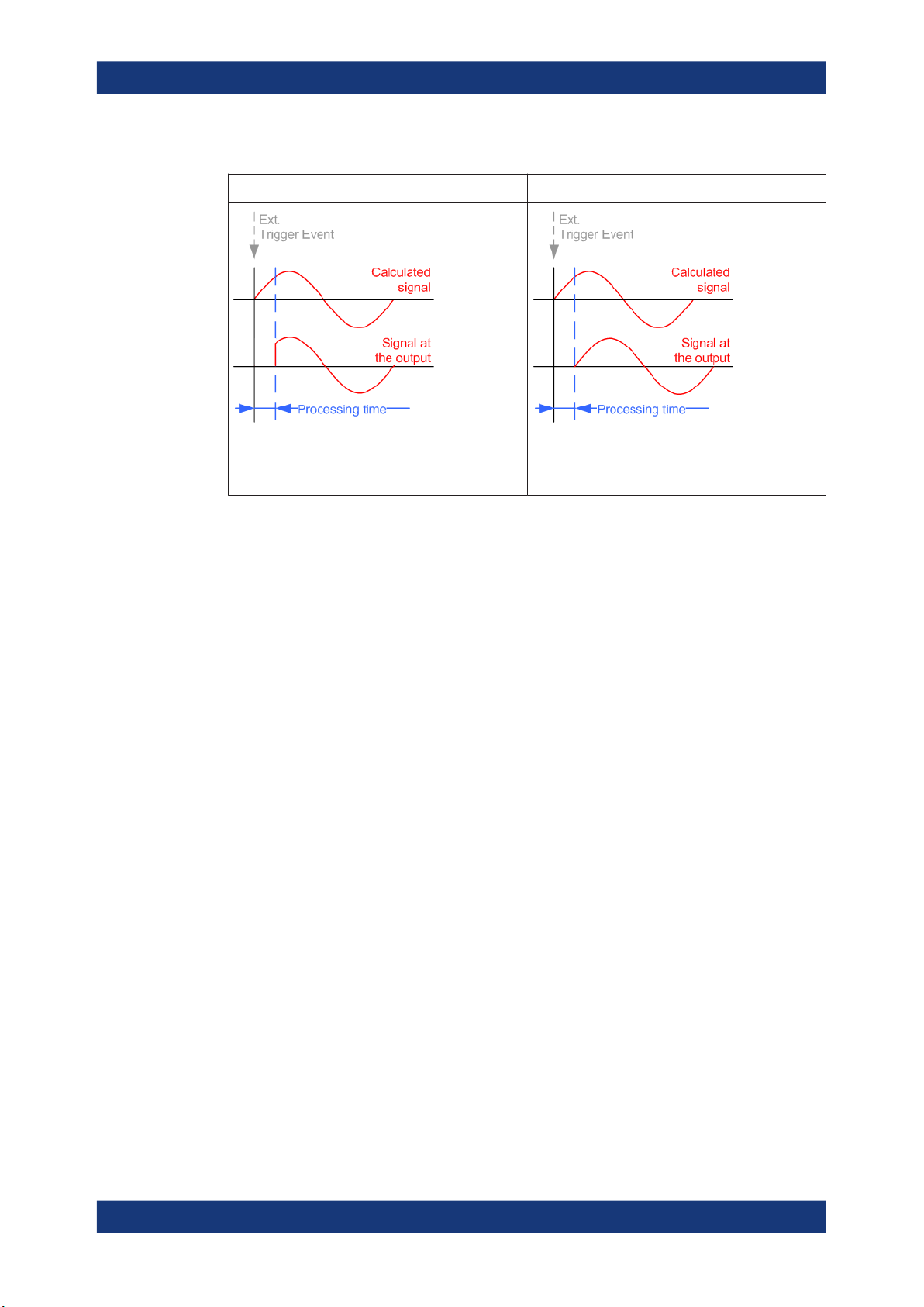
R&S®SMCV100B
Configuring internal baseband signals
Common functions and settings in the baseband domain
Table 4-3: Impact of the parameter Sync. Output to (External) Trigger
"Sync. Output to (External) Trigger = On" "Sync. Output to (External) Trigger = Off"
Suitable for long signal sequences
The output signal is synchronous to the trigger event
after elapsing of the internal processing time.
Suitable for triggering of short signal sequences with
signal duration comparable with the processing time
of the instrument
Suppressing and delaying trigger events
The main focus of the following features is the mobile communication standards.
●
"(External) Trigger Delay"
You can apply a definable number of symbols to delay the start trigger event of an
externally supplied trigger signal
This feature is useful to:
– Simulate the time delay between a base station signal and a user equipment
signal, for example during base station tests
– Compensate for known propagation delays or a timing offset in the test setups
●
"(External) Trigger Inhibit"
You can suppress the effect of a restarted trigger signal in the "Retrigger" trigger
mode for a definable number of symbols.
During base station tests, for example, this feature enables the trigger suppression
for a definable number of frames and yet the signal can still be generated synchronously. In each frame, the base station generates a trigger which would cause a
signal generation restart every time but for the suppression.
Example:
A trigger delay of 1000 samples means that after a trigger event, any subsequent trigger signal is ignored for the space of 1000 samples.
90User Manual 1179.0597.02 ─ 04
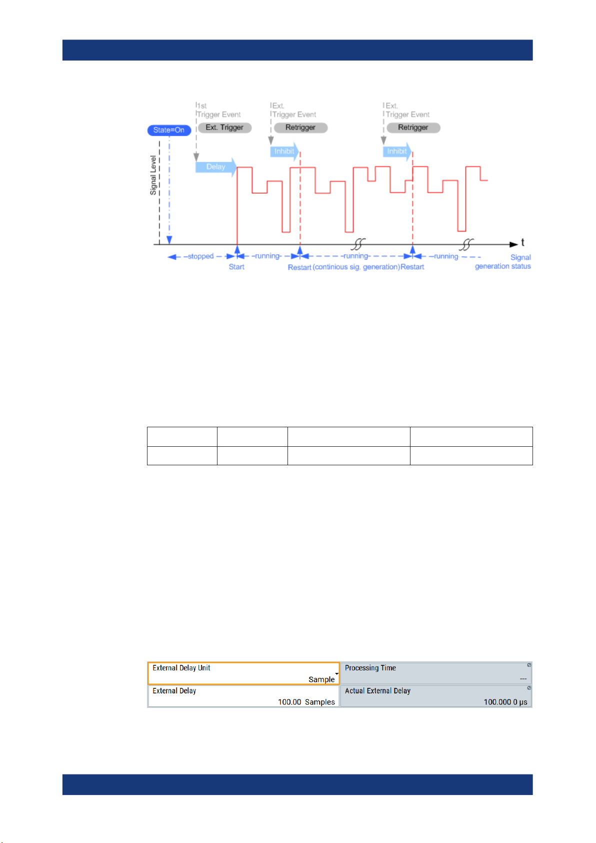
R&S®SMCV100B
Configuring internal baseband signals
Common functions and settings in the baseband domain
Figure 4-9: Trigger delay and trigger inhibit in trigger mode retrigger
Specifying delay and inhibit values
Trigger delay and inhibit values are expressed in the units of the generated signal, e.g.
in samples or symbols. You can also define the exact delay or inhibit period as a time
value, e.g. in seconds.
Trigger delay values t
exemplary instrument configuration and related t
depend on the instrument hardware. The table illustrates an
delay
values in samples (or symbols)
delay
and in seconds.
Option Max. rs / MHz t
Base unit 750 0 to depends on sample rate 0 to 1466
/ samples t
delay
delay
/ s
For more information, see the data sheet.
Example: Trigger delay and ARB clock frequency
The example is based on an ARB signal with 1 MHz clock frequency ("Baseband >
ARB > Clock Frequency = 1 MHz").
Step 1: Enable the following settings:
●
"ARB > Trigger In > Mode > Armed Auto"
●
"ARB > Trigger In > Source > External Global Trigger 1"
●
"ARB > Trigger In > External Delay Unit > Samples"
●
"ARB > Trigger In > External Delay = 100 Samples"
The parameter "Actual External Delay = 100 us" displays the time delay in seconds.
91User Manual 1179.0597.02 ─ 04
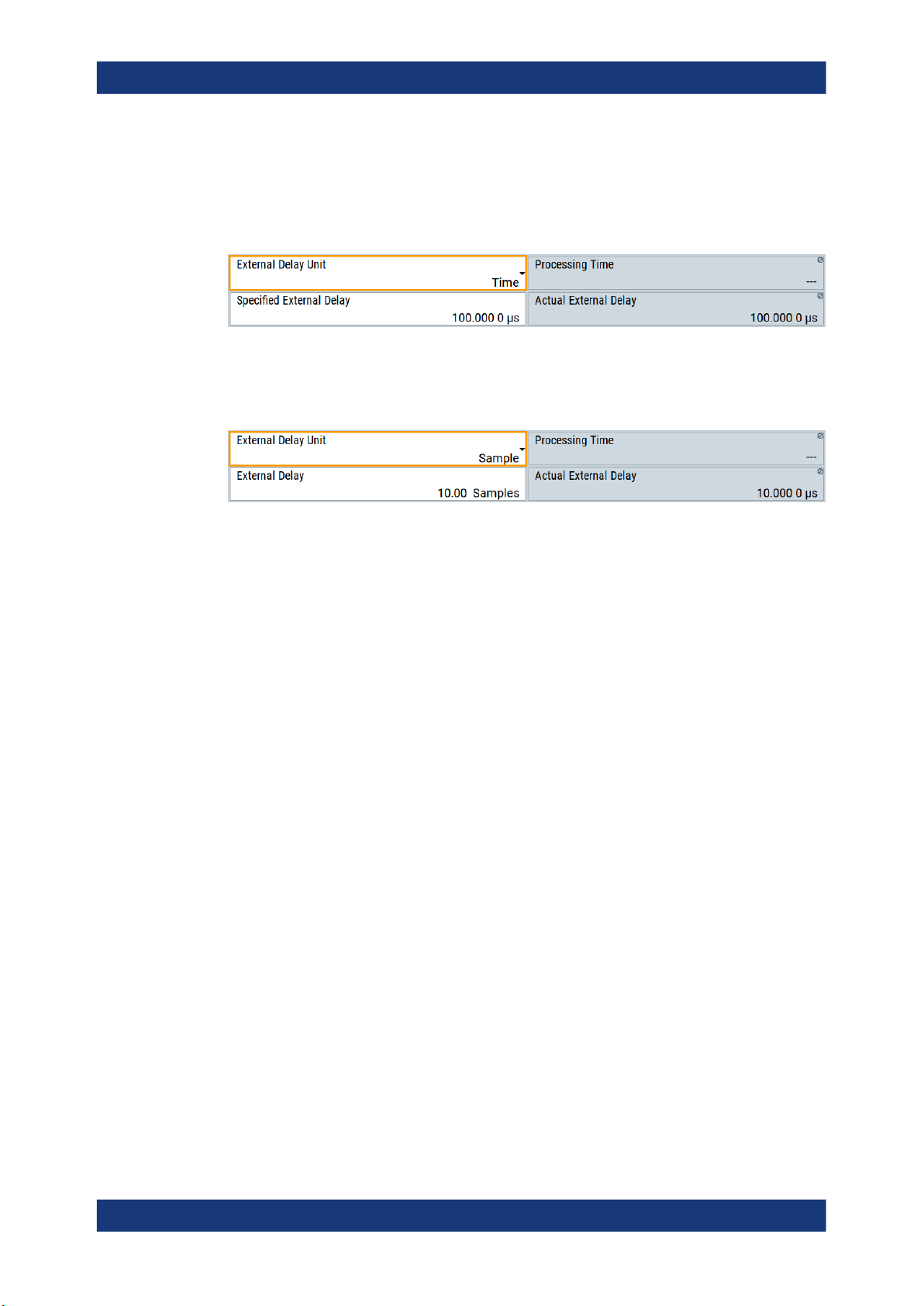
R&S®SMCV100B
Configuring internal baseband signals
Common functions and settings in the baseband domain
Step 2: Enable the following settings:
●
"ARB > Trigger In > External Delay Unit > Time"
●
"ARB > Trigger In > Specified External Delay = 10 us"
Logically, the "Actual External Delay" changes to 10 us.
Step 3:
●
Switch to "ARB > Trigger In > External Delay Unit > Samples".
The value of "ARB > Trigger In > External Delay" is 10 samples.
Receiving and providing trigger signals
In test setups that combine the signal of two or more instruments it is often required
that:
●
The signal generation starts at a defined moment
●
The signal generation starts simultaneously (or with an exactly defined delay) in all
involved instruments.
For information on triggering the R&S SMCV100B externally, see Chapter 3.3.3, "Trig-
gering the instrument with an external signal", on page 45.
4.4.1.4 Supported modulation signals
The R&S SMCV100B supports a range of predefined digital and analog modulation
signals. All related signals are baseband signals and digitally modulated onto the analog RF carrier.
In communication techniques, commonly used digital modulation schemes are based
on keying. From the several existing keying techniques, this instrument supports ASK
(amplitude shift keying), FSK (frequency shift keying), PSK (phase shift keying), and
QAM (quadrature amplitude modulation).
The digital modulation procedure is described by mapping. That is, by the assignment
of I and Q values (PSK and QAM) or frequency shifts (FSK) to every modulation symbol. The resulting modulated signal is graphically represented by a constellation diagram, in that each possible symbol is represented by a discrete point on a complex
plane. The number of used bits per symbol is a modulation parameter. The exact position of the symbols on the constellation diagram is determined by the used coding
scheme. You can also change the symbol position by applying rotation.
Most of the provided modulation schemes are implemented according to a communication standard. The QAM procedures 16QAM, 32QAM, 64QAM for instance have been
92User Manual 1179.0597.02 ─ 04

R&S®SMCV100B
Configuring internal baseband signals
Common functions and settings in the baseband domain
produced in accordance with ETSI standard ETS 300429 for digital video broadcasting
(DVB). The QAM procedures 256QAM and 1024QAM are not specified in this standard, but have been produced according to the same basic principles.
For all FSK procedures you can set the symbol rate f
up to a maximum value, see
SYMB
data sheet. The frequency deviation (FSK deviation) of the MSK modulation is permanently set to ¼ of the symbol rate. Also a variable FSK modulation with definable deviation per symbol is available and for even greater flexibility. A user-defined modulation
mapping can be applied, see "User mapping" on page 93.
User mapping
A user-defined modulation-mapping file can also be selected as modulation-mapping
source. Valid files have the extension *.vam and can be created with the
Rohde & Schwarz software tool-mapping wizard. The mapping wizard "mapwiz" is a
tool from Rohde & Schwarz designed for editing modulation schemes (for example
QPSK, 32QAM).
The main purpose of "mapwiz" is the assignment of logical symbol numbers to constellation points and the selection of modulation-specific parameters. Also, the tool supports the creation of nearly any arbitrarily chosen constellation diagram. The output of
"mapwiz" is a mapping file (*.vam) that can be imported into a R&S SMCV100B. The
program was developed on a 32-bit Microsoft Windows platform under MATLAB.
For more information, see "Introduction to "mapwiz" Mapping Editor" at the
Rohde & Schwarz webpage.
The remote commands required to define the modulation settings are described in
Chapter 13.15.3.2, "SOURce:BB:DM subsystem", on page 616.
Related settings:
●
Chapter 4.5.3.4, "Modulation settings", on page 110
4.4.1.5 Supported coding schemes
Coding is a technique used to improve the signal properties and signal reception and is
required only when using some types of modulation. In general, the coding schemes
are applied before modulation. The modulation symbols are coded directly before I and
Q values or frequency shifts are assigned. The applied coding is directly related to the
selected modulation methods. The relation implies that coding schemes are not freely
combinable with the modulation methods.
Refer to Chapter 4.5.5.1, "Common coding algorithms", on page 128 for overview on
the available coding combinations. This section also defines the modulation types for
which the various coding procedures can be used.
Related settings:
●
"Coding" on page 107
93User Manual 1179.0597.02 ─ 04

R&S®SMCV100B
4.4.1.6 Supported baseband filters
Configuring internal baseband signals
Common functions and settings in the baseband domain
In the wireless transmission technique, filters are applied to shape the baseband signal
before it is modulated on the RF. The selected baseband filter type and shape affect
the output stream, especially while generating broadband signals. If the filter is too narrow, it cuts the signal. If the filter is too wide, the signal could be distorted by some
unwanted signals.
To fulfill wide range of requirements, the R&S SMCV100B offers a wide selection of
predefined baseband filters. The predefined filters are designed for the special spectrum characteristics of the different communication standards. However, depending on
the selected filter form one or more filter parameters are provided for even more precise adjustment of the filter characteristic. You can select, for example, more steeper
edges or change the transition bandwidth. For more information on the provided settings, see "Impact of the filter parameters" on page 94.
The selection of user-defined filters offers even more flexibility. Use these filters if you
need filtering with filters of complex or proprietary form are required. For more information, refer to "User filter" on page 94.
Predefined baseband filters
See Chapter 4.5.5.2, "Predefined baseband filters", on page 130 for an overview of
available baseband filters.
User filter
The user filter file must have extension *.vaf and can be created with the
Rohde & Schwarz software tool filter wizard.
The filter wizard (filtwiz) is a tool from Rohde & Schwarz designed for creating filter
files that can be imported on a R&S SMCV100B. Its main purpose is the conversion of
user-defined finite impulse response (FIR) filters into the filter format (*.vaf). Beyond
this filtwiz provides designs for standard filters, e.g. root raised cosine (RRC), Gaussian.
The program was developed on a 32-bit Microsoft Windows platform under MATLAB.
For more information, see "Introduction to "filtwiz" Filter Editor" at the
Rohde & Schwarz webpage.
The remote commands required to define the filter settings are described in Chap-
ter 13.15.3.2, "SOURce:BB:DM subsystem", on page 616 and the corresponding sec-
tion in the user manual of each firmware option.
Related settings:
●
Chapter 4.5.3.5, "Filter settings", on page 112
●
Filter settings in the dialogs of the firmware options
Impact of the filter parameters
The following is a simple description of the filter parameters and the way they affect the
main filter characteristics. Changing filter parameters is an effective way to ensure that
94User Manual 1179.0597.02 ─ 04

R&S®SMCV100B
Configuring internal baseband signals
Common functions and settings in the baseband domain
the entire bandwidth of the desired signal is allowed to pass and adjust the filter form to
reach the spectrum mask requirements.
Cut Off Frequency
The cut-off frequency or corner frequency is a filter characteristic that defines the frequency at the 3 dB down point. This frequency is bound to the transition band; here the
filter characteristic changes form the passband to the stopband, where the signal is
suppressed.
Rolloff Factor
The rolloff factor is a measure for the excess bandwidth compared to the ideal bandwidth of a "brick like" filter. The roll off factor affects the steepness of the filter flanks. A
"Rolloff Factor" = 0 would result in the steepest theoretically possible flanks ; values
near to 1 make the flanks more flat.
Passband
The passband describes the frequency span that the filter passes unchanged. The
total passband of a filter is given as follows:
Bandwidth = (1 + "Roll Off Factor") * "Symbol Rate"
Cut Off Frequency Shift
The "Cut Off Frequency Shift" affects the cut-off frequency in the way that the filter
flanks are "moved" and the passband increases by "Cut Off Frequency Shift"*"Sample
Rate":
Cut Off Frequency = (1 + "Cut Off Frequency Shift") * "Sample
Rate"
95User Manual 1179.0597.02 ─ 04
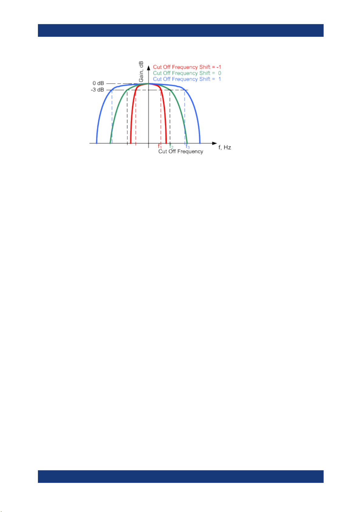
R&S®SMCV100B
Configuring internal baseband signals
Common functions and settings in the baseband domain
●
A "Cut Off Frequency Shift" = -1 results in a very narrow-band filter
●
Increasing the value up to 1 makes the filter more broad-band
●
By "Cut Off Frequency Shift" = 0, the -3 dB point is at the frequency determined by
the half of the selected "Sample Rate".
4.4.1.7 Methods for optimizing the crest factor
Communication standards utilizing higher order modulation techniques or using multiple carrier and complex signals consisting of the signals of more than one digital standard can feature a high crest factor. The signals of some digital standards can have
high crest factors also particularly with many channels and long sequences.
The crest factor represents the ratio of the peak voltage value to the RMS voltage
value, i.e. the peak to average ratio (PAR). The higher the crest factor and the resulting
dynamics of a signal, the greater the requirement for a power amplifier fed by the signal to be linear. A high crest factor arises for instance, when in a multi carrier signal the
carriers feature an identical start phase. This is based on the fact that the carriers are
periodically superposed that leads to high peak voltages in relation to the RMS voltage
values.
High crest factors entail two basic problems:
●
The nonlinearity of the power amplifier (compression) causes intermodulation
which expands the spectrum (spectral regrowth).
●
Since the level of the D/A converter is relative to the maximum value, the average
value is converted with a relatively low resolution. This leads to a high quantization
noise.
Both effects increase the adjacent-channel power.
Direct approaches
At the individual signal generation stages, the R&S SMCV100B offers different direct
approaches aimed to reduce the crest factor. While the corresponding parameters are
enabled, the implemented algorithms ensure minimizing the crest factor or achieving of
predefined target crest factor by applying of automatic settings. Methods of reducing
the crest factor differ regarding both the optimization achievable and the time required
for computation.
96User Manual 1179.0597.02 ─ 04

R&S®SMCV100B
Configuring internal baseband signals
Common functions and settings in the baseband domain
The provided crest factor reduction methods include:
●
Internal calculation of optimized carrier phases for the individual carriers in a multi
carrier signal
●
Automatic calculation of the carrier start phases in a multi-carrier continuous wave
signal
Applying clipping and filtering
Another common and simple approach for achieving a lower PAR is the combination of
clipping and filtering. In several of the firmware options, like 3GPP FDD or CDMA2000,
the instrument provides the possibility to enable baseband clipping and to select the
baseband filter and, when applicable, to adjust the filter characteristics.
●
Clipping is a technique that applies a wanted distortion to the signal.
The principle includes specifying a threshold, finding out the signal peaks once the
defined limits are exceeded and clipping them off. The level limit is specified as a
percentage of the highest peak value. Because clipping is done before filtering, the
procedure does not influence the spectrum. The error vector magnitude (EVM)
however increases.
The instrument offers two clipping modes:
– Vector | I + q |
The clipping limit is related to the amplitude | I + q |. The I and Q components
are mapped together, the angle is retained.
– Scalar | I | + | q |
The clipping limit is related to the absolute maximum of all the I and Q values | I
| + | q | . The I and Q components are mapped separately, the angle changes.
However, signal clipping not only changes the peak value but also the average
value and the effect on the crest factor is unpredictable.
97User Manual 1179.0597.02 ─ 04

R&S®SMCV100B
Configuring internal baseband signals
Common functions and settings in the baseband domain
Example:
The following figures demonstrate the effect of the clipping on the crest factor for typical scenarios.
Enabled is clipping with vector mode (|I+q|), using a signal configuration with 2 active
channels.
Constellation diagram of the signal without clipping,
shows the level mapping
●
Filtering is applied subsequently. The used filters are specially designed so that
they filter out the distortion.
4.4.2 Common settings
The start dialog of each digital standard follows a repeating dialog structure that comprises the tabs "General", "Trigger In", "Marker" and "Clock".
The "General" tab comprises the primary settings of the standard, the functions for
storing and recalling settings. It also provides access to further functions and dialogs,
like the "Filter" settings.
The "Trigger In", "Marker" and "Clock" tabs comprise the settings related to the corresponding function.
In the following, we use the "Custom Digital Modulation" dialog to explain the provided
common settings. The related remote-control commands are listed in the order "Custom Digital Modulation", "ARB", "Multi Carrier CW".
This section focuses on the available settings.
For more information refer to:
●
Chapter 4.4.1.3, "Baseband trigger signals", on page 84.
●
Chapter 4.4.1.2, "Regular marker output signals", on page 82
●
"Clock signals" on page 80
Constellation diagram with clipping level 80%, vector
mode (|I+q|) The circle emphasizes the changed
constellation points
98User Manual 1179.0597.02 ─ 04

R&S®SMCV100B
4.4.2.1 Trigger settings
Configuring internal baseband signals
Common functions and settings in the baseband domain
Routing and enabling a trigger
Use the Global connector settings to configure the signal mapping, the polarity, the trigger threshold and the input impedance of the input connectors.
To route and enable a trigger signal, perform the following general steps:
●
Define the signal source and the effect of a trigger event.
Select the "Trigger In > Mode" and "Trigger In > Source".
●
Define the connector where the selected signal is provided.
Use the "Global Connectors" settings.
Access:
► Select "Baseband > Custom Digital Mod > Trigger In".
This tab comprises the settings for selecting and configuring the trigger, like trigger
source, mode, and delay, and to arm or trigger an internal trigger manually. The current
signal generation status is displayed in the header of the tab together with information
on the enabled trigger mode. As in the "Marker" and "Clock" tabs, this tab provides
also access to the settings of the related connectors.
Settings:
Mode............................................................................................................................. 99
Signal Duration............................................................................................................100
Running/Stopped........................................................................................................ 100
Arm..............................................................................................................................100
Execute Trigger...........................................................................................................100
Source.........................................................................................................................100
Sync. Output to External Trigger/Sync. Output to Trigger...........................................101
External / Trigger Inhibit..............................................................................................101
(External) Delay Unit...................................................................................................101
(Specified) External Delay/(Specified) Trigger Delay..................................................101
Actual Trigger Delay/Actual External Delay................................................................ 102
Mode
Selects a regular trigger signal: "Auto", "Retrigger", "Armed_Auto", "Armed_Retrigger",
or "Single".
Refer to "Impact of the trigger modes on the signal generation" on page 85 for a
detailed description of the provided trigger modes.
99User Manual 1179.0597.02 ─ 04

R&S®SMCV100B
Configuring internal baseband signals
Common functions and settings in the baseband domain
Remote command:
[:SOURce<hw>]:BB:DM[:TRIGger]:SEQuence on page 629
[:SOURce<hw>]:BB:ARBitrary[:TRIGger]:SEQuence on page 677
Signal Duration
Enters the length of the signal sequence to be output in the "Single" trigger mode.
Use this parameter to output part of the signal deliberately, an exact sequence of the
signal, or a defined number of repetitions of the signal.
Remote command:
[:SOURce<hw>]:BB:DM:TRIGger:SLENgth on page 630
[:SOURce<hw>]:BB:ARBitrary:TRIGger:SLUNit on page 678
Running/Stopped
With enabled modulation, displays the status of signal generation for all trigger modes.
●
"Running"
The signal is generated; a trigger was (internally or externally) initiated in triggered
mode.
●
"Stopped"
The signal is not generated and the instrument waits for a trigger event.
Remote command:
[:SOURce<hw>]:BB:DM:TRIGger:RMODe? on page 630
[:SOURce<hw>]:BB:ARBitrary:TRIGger:RMODe? on page 678
Arm
Stops the signal generation until subsequent trigger event occurs.
Remote command:
[:SOURce<hw>]:BB:DM:TRIGger:ARM:EXECute on page 631
[:SOURce<hw>]:BB:ARBitrary:TRIGger:ARM:EXECute on page 678
Execute Trigger
For internal trigger source, executes trigger manually.
Remote command:
[:SOURce<hw>]:BB:DM:TRIGger:EXECute on page 631
[:SOURce<hw>]:BB:ARBitrary:TRIGger:EXECute on page 679
Source
The following sources of the trigger signal are available:
●
"Internal"
The trigger event is executed manually by the "Execute Trigger".
●
"External Global Trigger"
The trigger event is the active edge of an external trigger signal provided and configured at the User x connectors.
The polarity, the trigger threshold, and the input impedance of the input connectors can
be configured in the "Global connector settings" dialog.
See "Trigger sources" on page 85
See also Chapter 11.2, "Configuring global connectors", on page 434.
100User Manual 1179.0597.02 ─ 04
 Loading...