


EUTRA/LTE/IoT
R&S®SMBVB-K55/-K84/-K85/-K112/-
K113/-K115/-K119/-K143/-K146/-K175
User Manual
(;Üßì2)
1178819402
Version 09

This document describes the following software options:
●
R&S®SMBVB-K55, LTE Rel. 8 (1423.7830.xx)
●
R&S®SMBVB-K84, LTE Rel. 9 (1423.7901.xx)
●
R&S®SMBVB-K85, LTE Rel. 10 (1423.7918.xx)
●
R&S®SMBVB-K112, LTE Rel. 11 (1423.8037.xx)
●
R&S®SMBVB-K113, LTE Rel. 12 (1423.8043.xx)
●
R&S®SMBVB-K115, Cellular IoT Rel. 13 (1424.8108.xx)
●
R&S®SMBVB-K119, LTE Rel. 13/ Rel. 14/ Rel. 15 (1423.8066.xx)
●
R&S®SMBVB-K143, Cellular IoT Rel. 14 (1423.8637.xx)
●
R&S®SMBVB-K146, Cellular IoT Rel. 15 (1423.8808.xx)
●
R&S®SMBVB-K175, U-plane generation (1423.8989.xx)
This manual describes firmware version FW 5.00.044.xx and later of the R&S®SMBV100B.
© 2021 Rohde & Schwarz GmbH & Co. KG
Mühldorfstr. 15, 81671 München, Germany
Phone: +49 89 41 29 - 0
Email: info@rohde-schwarz.com
Internet: www.rohde-schwarz.com
Subject to change – data without tolerance limits is not binding.
R&S® is a registered trademark of Rohde & Schwarz GmbH & Co. KG.
Trade names are trademarks of the owners.
1178.8194.02 | Version 09 | EUTRA/LTE/IoT
The following abbreviations are used throughout this manual: R&S®SMBV100B is abbreviated as R&S SMBVB, R&S®WinIQSIM2
is abbreviated as R&S WinIQSIM2
TM

ContentsEUTRA/LTE/IoT
Contents
1 Welcome to the EUTRA/LTE/IoT options........................................... 13
1.1 Key features.................................................................................................................13
1.2 Accessing the EUTRA/LTE dialog............................................................................. 15
1.3 What's new...................................................................................................................15
1.4 Documentation overview............................................................................................15
1.4.1 Getting started manual..................................................................................................16
1.4.2 User manuals and help................................................................................................. 16
1.4.3 Service manual............................................................................................................. 16
1.4.4 Instrument security procedures.....................................................................................16
1.4.5 Printed safety instructions............................................................................................. 16
1.4.6 Data sheets and brochures........................................................................................... 17
1.4.7 Release notes and open source acknowledgment (OSA)............................................ 17
1.4.8 Application notes, application cards, white papers, etc.................................................17
1.5 Scope........................................................................................................................... 17
1.6 Notes on screenshots.................................................................................................18
2 About the EUTRA/LTE options........................................................... 19
2.1 Required options.........................................................................................................19
2.2 Introduction to the EUTRA/LTE technology............................................................. 19
2.2.1 LTE downlink transmission scheme.............................................................................. 20
2.2.1.1 OFDMA parameterization............................................................................................. 21
Channel bandwidth....................................................................................................... 21
Frame structure type 1 (FDD)....................................................................................... 21
Frame structure type 2 (TDD)....................................................................................... 22
2.2.1.2 Downlink resource grid..................................................................................................23
2.2.1.3 Downlink data transmission.......................................................................................... 24
2.2.1.4 Downlink control information transmission....................................................................24
2.2.1.5 Downlink reference signal structure and cell search.....................................................26
Mapping of reference signals to antenna ports............................................................. 26
Cell-specific downlink reference signals....................................................................... 27
MBSFN reference signals............................................................................................. 29
UE-specific reference signal (DMRS)........................................................................... 30
3User Manual 1178.8194.02 ─ 09

ContentsEUTRA/LTE/IoT
Positioning reference signals........................................................................................ 31
CSI reference signals....................................................................................................32
2.2.1.6 Downlink physical layer procedures..............................................................................33
2.2.2 LTE uplink transmission scheme...................................................................................33
2.2.2.1 SC-FDMA parameterization.......................................................................................... 35
2.2.2.2 Uplink data transmission............................................................................................... 35
2.2.2.3 Uplink control information transmission........................................................................ 36
2.2.2.4 Uplink reference signal structure...................................................................................38
2.2.2.5 Uplink physical layer procedures.................................................................................. 39
2.2.3 LTE MIMO concepts......................................................................................................41
2.2.3.1 Downlink MIMO.............................................................................................................41
Spatial multiplexing....................................................................................................... 41
Transmit diversity.......................................................................................................... 44
Beamforming.................................................................................................................44
2.2.3.2 Uplink MIMO................................................................................................................. 44
2.2.4 LTE MBMS concepts.....................................................................................................45
2.2.5 LTE Release 10 (LTE-Advanced) introduction.............................................................. 45
2.2.5.1 Carrier aggregation....................................................................................................... 45
2.2.5.2 Enhanced uplink SC-FDMA.......................................................................................... 47
2.2.5.3 Enhanced MIMO schemes............................................................................................48
2.2.6 LTE Release 11 introduction......................................................................................... 50
2.2.7 LTE Release 12 introduction......................................................................................... 53
2.2.8 LTE Release 13/14 introduction.................................................................................... 54
2.2.8.1 Frame structure type 3 (LAA) and partial subframes.................................................... 55
2.2.8.2 DCI format 1C............................................................................................................... 56
2.2.8.3 Physical channels and signals in an LAA SCell............................................................ 57
2.2.8.4 Full dimension MIMO (FD-MIMO)................................................................................. 58
2.2.8.5 PUCCH formats 4 and 5............................................................................................... 59
2.2.8.6 TDD special subframe configuration 10........................................................................ 59
2.2.8.7 DMRS enhancements and DCI format 2C/2D.............................................................. 59
3 Find out the implemented 3GPP specification..................................61
4 EUTRA/LTE configuration and settings............................................. 62
4.1 General settings.......................................................................................................... 62
4User Manual 1178.8194.02 ─ 09

ContentsEUTRA/LTE/IoT
4.2 General DL settings / general TDD DL settings....................................................... 68
4.2.1 PDSCH scheduling settings.......................................................................................... 69
4.2.2 DL carrier aggregation configuration.............................................................................71
4.2.2.1 About DL carrier aggregation........................................................................................ 71
4.2.2.2 How to enable carrier aggregation and cross-carrier scheduling..................................72
4.2.2.3 Carrier aggregation settings..........................................................................................74
4.2.3 MBSFN settings............................................................................................................ 78
4.2.4 Physical settings........................................................................................................... 92
4.2.5 Cell-specific settings..................................................................................................... 96
4.2.6 TDD frame structure settings...................................................................................... 100
4.2.7 Downlink signals settings............................................................................................ 101
4.2.7.1 Synchronization and cell-specific reference signals (CRS/SYNC) settings................ 101
4.2.7.2 NB-IoT synchronization and cell-specific reference signals (NRS/N-SYNC) settings.102
4.2.7.3 Positioning reference signal (PRS) settings................................................................104
4.2.7.4 CSI-RS settings...........................................................................................................108
4.2.7.5 Discovery reference signals (DRS) settings................................................................114
4.2.7.6 Narrowband positioning reference signals (NPRS) settings....................................... 120
4.2.7.7 NB-IoT wake-up signal (NWUS) settings.................................................................... 122
4.2.8 Antenna ports settings................................................................................................ 124
4.3 DL frame configuration settings..............................................................................126
4.3.1 General frame configuration settings.......................................................................... 126
4.3.2 Dummy data configuration settings.............................................................................128
4.3.3 User configuration settings..........................................................................................129
4.3.4 Auto sequence configuration.......................................................................................137
4.3.4.1 How to enable and use the auto sequence mode.......................................................138
4.3.4.2 Auto sequence settings...............................................................................................141
4.3.5 EPDCCH configuration settings.................................................................................. 146
4.3.6 Scrambling configuration settings............................................................................... 151
4.3.7 SPS configuration settings.......................................................................................... 152
4.3.8 LAA settings................................................................................................................ 157
4.3.9 Subframe configuration settings..................................................................................162
4.3.10 DL resource allocation table........................................................................................163
4.3.11 PCFICH settings......................................................................................................... 170
5User Manual 1178.8194.02 ─ 09

ContentsEUTRA/LTE/IoT
4.3.12 PHICH settings............................................................................................................172
4.3.13 (E)PDCCH settings..................................................................................................... 175
4.3.14 (E)PDCCH format variable..........................................................................................179
4.3.15 DCI format configuration............................................................................................. 188
4.4 Enhanced PBCH, PDSCH and PMCH settings....................................................... 201
4.4.1 Precoding settings.......................................................................................................202
4.4.2 CSI-RS settings...........................................................................................................207
4.4.3 Scrambling settings.....................................................................................................208
4.4.4 Channel coding settings..............................................................................................209
4.5 DL antenna port mapping settings.......................................................................... 211
4.6 General UL settings.................................................................................................. 217
4.6.1 UL carrier aggregation configuration...........................................................................218
4.6.1.1 About UL carrier aggregation...................................................................................... 219
4.6.1.2 How to enable UL carrier aggregation........................................................................ 219
4.6.1.3 Carrier aggregation settings........................................................................................222
4.6.2 Physical settings......................................................................................................... 224
4.6.3 Cell-specific settings................................................................................................... 228
4.6.4 TDD frame structure settings...................................................................................... 231
4.6.5 Signals settings........................................................................................................... 232
4.6.5.1 UL reference signals................................................................................................... 232
4.6.5.2 Cell-specific SRS settings........................................................................................... 234
4.6.6 PRACH settings.......................................................................................................... 236
4.6.7 PUSCH structure.........................................................................................................238
4.6.8 PUCCH structure........................................................................................................ 239
4.7 UL frame configuration settings..............................................................................242
4.7.1 General scheduling configuration settings.................................................................. 242
4.7.2 Subframe configuration............................................................................................... 245
4.7.3 UL allocation table.......................................................................................................247
4.8 User equipment configuration................................................................................. 252
4.8.1 Common settings........................................................................................................ 253
4.8.2 Physical uplink control channel (PUCCH)...................................................................255
4.8.3 FRC configuration....................................................................................................... 256
4.8.4 Physical uplink shared channel (PUSCH)...................................................................260
6User Manual 1178.8194.02 ─ 09

ContentsEUTRA/LTE/IoT
4.8.5 Demodulation reference signal (DMRS)..................................................................... 265
4.8.6 Sounding reference signal (SRS)................................................................................267
4.8.7 Sidelink settings.......................................................................................................... 277
4.8.7.1 Common sidelink settings........................................................................................... 277
4.8.7.2 Resource pool control and resource pool settings...................................................... 279
4.8.7.3 Resource pool data settings........................................................................................285
4.8.7.4 RMC settings...............................................................................................................289
4.8.7.5 Synchronization settings............................................................................................. 290
4.8.7.6 SCI configuration settings........................................................................................... 292
4.8.7.7 SCI format configuration............................................................................................. 295
4.8.7.8 Allocation settings....................................................................................................... 298
4.8.7.9 PSCCH, PSDCH and PSSCH enhanced settings...................................................... 301
4.8.8 Antenna port mapping.................................................................................................303
4.8.9 PRACH power ramping...............................................................................................306
4.8.10 PRACH configuration.................................................................................................. 307
4.9 Enhanced PUSCH settings.......................................................................................310
4.9.1 Common PUSCH settings...........................................................................................310
4.9.2 Demodulation reference signal (DMRS)..................................................................... 313
4.9.3 Channel coding / multiplexing..................................................................................... 314
4.10 Enhanced PUCCH settings...................................................................................... 320
4.10.1 Common settings........................................................................................................ 320
4.10.2 Channel coding / multiplexing..................................................................................... 322
4.10.3 Demodulation reference signal (DMRS)..................................................................... 326
5 Generating eMTC/NB-IoT signals..................................................... 328
5.1 About eMTC............................................................................................................... 329
5.1.1 Physical layer.............................................................................................................. 331
5.1.2 PBCH.......................................................................................................................... 332
5.1.3 PDSCH........................................................................................................................332
5.1.4 MPDCCH.................................................................................................................... 336
5.1.5 PUSCH........................................................................................................................340
5.1.6 PUCCH....................................................................................................................... 343
5.1.7 PRACH........................................................................................................................345
5.2 About NB-IoT............................................................................................................. 346
7User Manual 1178.8194.02 ─ 09

ContentsEUTRA/LTE/IoT
5.2.1 Physical layer.............................................................................................................. 347
5.2.2 NPSS and NSSS.........................................................................................................350
5.2.3 NRS.............................................................................................................................351
5.2.4 NPBCH........................................................................................................................352
5.2.5 NPDCCH.....................................................................................................................353
5.2.6 NPDSCH..................................................................................................................... 357
5.2.7 NDRS.......................................................................................................................... 359
5.2.8 NPUSCH..................................................................................................................... 360
5.2.9 NPRACH..................................................................................................................... 363
5.3 eMTC/NB-IoT-specific configuration and settings.................................................366
5.3.1 NB-IoT carrier allocation............................................................................................. 367
5.3.2 NPBCH, NPDCCH and NPDSCH settings..................................................................374
5.3.2.1 Search space settings.................................................................................................377
5.3.2.2 NB-IoT DCI configuration............................................................................................ 379
5.3.2.3 NB-IoT allocations (NPBCH, NPDCCH, NPDSCH).................................................... 393
5.3.2.4 NPBCH channel coding and MIB-NB configuration.................................................... 397
5.3.2.5 NPDSCH and NPDCCH channel coding and scrambling........................................... 401
5.3.3 FRC settings............................................................................................................... 404
5.3.4 NDMRS settings..........................................................................................................407
5.3.5 NPUSCH settings........................................................................................................409
5.3.5.1 NB-IoT allocation settings........................................................................................... 412
5.3.5.2 NPUSCH enhanced settings.......................................................................................417
5.3.6 NPRACH settings........................................................................................................421
5.3.7 eMTC DL allocations settings..................................................................................... 427
5.3.7.1 eMTC DL valid subframes and frequency hopping..................................................... 427
5.3.7.2 Search space settings.................................................................................................430
5.3.7.3 eMTC DCI configuration..............................................................................................432
5.3.7.4 eMTC allocations (PBCH, MPDCCH, PDSCH)...........................................................444
5.3.7.5 PBCH channel coding and SIB-BR configuration....................................................... 448
5.3.7.6 PDSCH channel coding and scrambling..................................................................... 451
5.3.7.7 MPDCCH configuration...............................................................................................456
5.3.8 eMTC PUSCH settings............................................................................................... 457
5.3.8.1 Cell-specific eMTC PUSCH settings........................................................................... 459
8User Manual 1178.8194.02 ─ 09

ContentsEUTRA/LTE/IoT
5.3.8.2 UE-specific eMTC PUSCH transmissions settings..................................................... 459
5.3.8.3 eMTC PUSCH channel coding and multiplexing settings........................................... 465
5.3.9 eMTC PUCCH settings............................................................................................... 469
5.3.9.1 Cell-specific eMTC PUCCH settings...........................................................................471
5.3.9.2 UE-specific eMTC PUCCH settings............................................................................ 473
5.3.9.3 eMTC PUCCH channel coding and multiplexing settings........................................... 473
5.3.10 eMTC PRACH settings............................................................................................... 476
6 Observing current allocations on the time plan..............................482
6.1 OFDMA time plan...................................................................................................... 482
6.2 SC-FDMA time plan...................................................................................................484
6.3 TDD time plan............................................................................................................ 485
6.4 eMTC/NB-IoT indication in the DL time plan...........................................................486
6.5 eMTC/NB-IoT indication in the UL time plan...........................................................489
6.6 TDD time plan............................................................................................................ 490
7 Performing BS tests according to TS 36.141.................................. 493
7.1 Introduction to conformance testing...................................................................... 493
7.1.1 UE conformance testing..............................................................................................493
7.1.2 BS conformance testing.............................................................................................. 495
7.1.3 Repeater conformance testing.................................................................................... 495
7.2 Required options.......................................................................................................495
7.3 Supported test cases................................................................................................495
7.3.1 Generic structure of the description of the implemented test cases........................... 496
7.4 Standard test setups.................................................................................................497
7.4.1 Standard test setup - one path....................................................................................497
7.5 General considerations............................................................................................ 497
7.6 User interface............................................................................................................ 501
7.6.1 Test case settings........................................................................................................501
7.6.2 Instrument settings......................................................................................................503
7.6.3 Frequency allocation settings......................................................................................504
7.6.4 Wanted signal and cell-specific settings......................................................................505
7.6.5 Diagram.......................................................................................................................507
7.6.6 Apply settings..............................................................................................................507
7.7 Transmitter characteristics (TS 36.141, chapter 6)................................................ 507
9User Manual 1178.8194.02 ─ 09

ContentsEUTRA/LTE/IoT
7.7.1 Prior considerations.................................................................................................... 508
7.7.2 Introduction to the unwanted emissions tests............................................................. 508
7.7.3 General workflow for carrying out a transmitter test....................................................510
7.7.4 Interfering signal settings............................................................................................ 512
7.7.5 Test case 6.7: transmitter intermodulation.................................................................. 514
7.8 Receiver characteristics (TS 36.141, chapter 7).....................................................515
7.8.1 Prior considerations.................................................................................................... 516
7.8.2 General workflow for carrying out a receiver test........................................................517
7.8.3 Interfering signal settings............................................................................................ 518
7.8.4 Test case 7.2: reference sensitivity level.....................................................................521
7.8.5 Test case 7.3: dynamic range..................................................................................... 522
7.8.6 Test case 7.4: in-channel selectivity (ICS).................................................................. 524
8 Generating user plane data...............................................................527
8.1 Required options.......................................................................................................527
8.2 File format and folder structure...............................................................................527
9 Signal control and signal characteristics........................................529
9.1 Time domain windowing settings............................................................................529
9.2 Filter/clipping/ARB settings..................................................................................... 530
9.2.1 Filter settings...............................................................................................................530
9.2.2 Clipping settings..........................................................................................................536
9.2.3 ARB settings............................................................................................................... 537
9.3 Adjusting the signal power...................................................................................... 538
9.3.1 General power-related settings overview....................................................................538
9.3.2 Downlink power-related settings overview.................................................................. 538
9.3.3 Uplink power-related settings overview.......................................................................539
9.3.4 Power settings.............................................................................................................540
9.4 Trigger settings......................................................................................................... 543
9.5 Marker settings..........................................................................................................548
9.6 Clock settings............................................................................................................551
9.7 Global connectors settings......................................................................................552
10 Remote-control commands...............................................................553
10.1 Primary commands...................................................................................................555
10User Manual 1178.8194.02 ─ 09

ContentsEUTRA/LTE/IoT
10.2 Filter/clipping/power................................................................................................. 559
10.2.1 Filter settings...............................................................................................................559
10.2.2 Clipping settings..........................................................................................................563
10.2.3 Time domain windowing settings................................................................................ 564
10.2.4 Power settings.............................................................................................................565
10.3 Clock.......................................................................................................................... 567
10.4 Timing configuration.................................................................................................568
10.5 Trigger........................................................................................................................568
10.6 Marker........................................................................................................................ 573
10.7 General TDD commands.......................................................................................... 576
10.8 General downlink commands.................................................................................. 577
10.9 General uplink commands....................................................................................... 590
10.10 DL frame configuration.............................................................................................602
10.11 DL MBFSN..................................................................................................................611
10.12 DL carrier aggregation..............................................................................................623
10.13 CSI-RS........................................................................................................................ 628
10.14 LAA and DRS.............................................................................................................635
10.15 Enhanced PBCH, PDSCH, PMCH.............................................................................645
10.16 Enhanced PCFICH, PHICH and PDCCH configuration.......................................... 654
10.17 Auto sequence.......................................................................................................... 689
10.18 UL frame configuration.............................................................................................701
10.19 UL carrier aggregation..............................................................................................706
10.20 UL enhanced..............................................................................................................710
10.21 User configuration.................................................................................................... 726
10.22 EPDCCH..................................................................................................................... 738
10.23 Dummy data configuration.......................................................................................742
10.24 SPS configuration..................................................................................................... 744
10.25 User equipment......................................................................................................... 745
10.26 Sidelink configuration.............................................................................................. 770
10.27 eMTC/NB-IoT commands..........................................................................................799
10.27.1 General IoT downlink.................................................................................................. 823
10.27.1.1 Physical settings......................................................................................................... 823
10.27.1.2 DL reference and sychronization signals.................................................................... 824
11User Manual 1178.8194.02 ─ 09

ContentsEUTRA/LTE/IoT
10.27.1.3 NPRS.......................................................................................................................... 825
10.27.1.4 NB-IoT wake-up signal................................................................................................829
10.27.1.5 NB-IoT carrier allocation............................................................................................. 831
10.27.1.6 eMTC bitmap, valid subframes, hopping and common search space........................ 838
10.27.2 DL IoT frame configuration..........................................................................................843
10.27.2.1 NB-IoT DCI configuration............................................................................................ 843
10.27.2.2 NB-IoT allocation.........................................................................................................854
10.27.2.3 NPBCH, NPDCCH, NPDSCH enhanced settings.......................................................858
10.27.2.4 NB-IoT user configuration........................................................................................... 863
10.27.2.5 eMTC DCI configuration..............................................................................................864
10.27.2.6 eMTC allocations........................................................................................................ 878
10.27.2.7 PBCH and PDSCH enhanced settings....................................................................... 883
10.27.2.8 MPDCCH configuration...............................................................................................892
10.27.3 General IoT uplink.......................................................................................................894
10.27.4 IoT UE configuration................................................................................................... 902
10.28 Test case wizard remote-control commands..........................................................933
Annex.................................................................................................. 944
A Conflict handling................................................................................944
A.1 Downlink.................................................................................................................... 944
A.2 Uplink......................................................................................................................... 945
A.3 DCI conflict handling................................................................................................ 946
B Subframes handling...........................................................................949
B.1 Copy/paste subframe................................................................................................949
B.2 Number of configurable subframes........................................................................ 949
B.3 Four configurable frames in uplink and downlink direction.................................950
B.3.1 Uplink direction............................................................................................................950
B.3.2 Downlink direction....................................................................................................... 952
Glossary: 3GPP specifications, references.....................................954
List of commands.............................................................................. 956
Index....................................................................................................980
12User Manual 1178.8194.02 ─ 09

Welcome to the EUTRA/LTE/IoT optionsEUTRA/LTE/IoT
Key features
1 Welcome to the EUTRA/LTE/IoT options
The R&S SMBV100B-K55/-K84/-K85/-K112/-K113/-K115/-K119/-K143/-K145/-K175 are
firmware applications that add functionality to generate signals in accordance with the
3GPP standard EUTRA/LTE.
In the following, the terms LTE and EUTRA are used interchangeably.
1.1 Key features
Preamble
All supported LTE features are in line with 3GPP Release 14; the following official
3GPP specifications are implemented:
●
3GPP TS 36.211, version 15.6.0
●
3GPP TS 36.212, version 15.6.1
●
3GPP TS 36.213, version 15.6.0
The R&S SMBV100B-K55/-K84/-K85/-K112/-K113/-K119 key features
The R&S SMBV100B simulates EUTRA/LTE at the physical channel level. The following list gives an overview of the functions provided for generating an EUTRA/LTE signal:
●
Supports FDD and TDD
●
Intuitive user interface with graphical display of time plan
●
Full support of P-SYNC, S-SYNC and DL reference signal derived from cell ID
●
PBCH, PDSCH, (E)PDCCH, PCFICH, PHICH supported
●
Downlink 256QAM for PDSCH and PMCH
●
PDCCH with full DCI configuration (all DCI formats supported), incl. DCI format 1C
for eIMTA-RNTI
●
Channel coding and scrambling for PDSCH and PBCH (including MIB)
●
Automatic PDSCH scheduling from DCI
●
Automatic scheduling of downlink transmissions according to long HARQ patterns
●
Full downlink MIMO and transmit diversity support
●
Uplink MIMO support
●
Supports PUSCH with channel coding and scrambling
●
Configuration of all PRACH and PUCCH formats
●
Fixed reference channels (FRC) in line with 3GPP TS 36.141
●
Downlink test models (E-TMs) in line with 3GPP TS 36.141, incl. E-TMs for
256QAM
●
Test case wizard
13User Manual 1178.8194.02 ─ 09

Welcome to the EUTRA/LTE/IoT optionsEUTRA/LTE/IoT
Key features
●
Simulation of single-layer, dual-layer and up to eight-layer beamforming scenarios
(transmission modes 7, 8 and 9) on antenna ports 5 and 7 to 14
●
Support of MBMS single frequency network (MBSFN) subframes on antenna port 4
●
Generation of positioning reference signals (PRS) on antenna port 6
●
Generation of LTE-Advanced downlink and uplink carrier aggregation scenarios (up
to 5 carriers) with support for cross-carrier scheduling; incl. uplink carrier aggregation with mixed duplexing
●
LTE-Advanced enhanced SC-FDMA with PUSCH/PUCCH synchronous transmission and clustered PUSCH
●
Support of CSI reference signals
●
Support of DL LAA bursts configuration
●
Support of QAM256 in uplink
The R&S SMBV100B-K115 key features
The R&S SMBV100B simulates eMTC and NB-IoT at the physical channel level. The
following is an overview of provided functions:
●
Supports uplink eMTC and NB-IoT configuration, and downlink NB-IoT configuration for CAT-M1 and CAT-NB1 devices
●
Supports IoT standalone configuration and mixed configuration with LTE
●
Supports NB-IoT in-band and guard band operating modes
●
Intuitive user interface with graphical display of time plan
●
Support of coverage enhancement CE modes A and B and CE levels 0, 1 and 2
●
Support of the new NB channels and synchronization signals (NPSS, NSSS and
DL reference signal derived from NCell ID)
●
MPBCH, PDSCH, PBCH supported
●
DCI-based configuration of NPDCCH and NPDSCH
●
Channel coding and scrambling for NPDCCH, NPDSCH and NPBCH (including
SIB type 1)
●
Supports NPUSCH with channel coding and scrambling
●
NPRACH configuration
●
Support of all specified modulation schemes
The R&S SMBV100B-K143 key features
●
3GPP LTE Rel. 14 (eMTC and NB-IoT)
Introduces eMTC widebands and new types CAT-M2 and CAT-NB2 devices.
The R&S SMBV100B-K146 key features
●
3GPP LTE Rel. 15 (NB-IoT)
Introduces NB-IoT TDD mode in UL, FDD NPRACH formats, early data transmission, NB-IoT wake up signal and scheduling request in uplink for NPUSCH F2.
This user manual contains a description of the functionality that the application provides, including remote control operation.
14User Manual 1178.8194.02 ─ 09

Welcome to the EUTRA/LTE/IoT optionsEUTRA/LTE/IoT
All functions not discussed in this manual are the same as in the base unit and are
described in the R&S SMBV100B user manual. The latest version is available at:
www.rohde-schwarz.com/manual/SMBV100B
Installation
You can find detailed installation instructions in the delivery of the option or in the
R&S SMBV100B service manual.
1.2 Accessing the EUTRA/LTE dialog
To open the dialog with EUTRA/LTE settings
► In the block diagram of the R&S SMBV100B, select "Baseband > EUTRA/LTE".
A dialog box opens that display the provided general settings.
Documentation overview
The signal generation is not started immediately. To start signal generation with the
default settings, select "State > On".
1.3 What's new
This documentation describes version 5.00.044 and higher of the EUTRA/LTE/IoT firmware application. Compared to version 4.90.049, it provides the following new features
and changes:
●
Support of test models for O-RAN, see "Test Models" on page 66
●
Flexible configuration of starting seed for data sources for PDSCH, see "Data
Source Init" on page 135
●
Flexible configuration of starting seed for data sources for PUSCH, see "Initializa-
tion (tab General)" on page 262
1.4 Documentation overview
This section provides an overview of the R&S SMBV100B user documentation. Unless
specified otherwise, you find the documents on the R&S SMBV100B product page at:
www.rohde-schwarz.com/manual/smbv100b
15User Manual 1178.8194.02 ─ 09

1.4.1 Getting started manual
Introduces the R&S SMBV100B and describes how to set up and start working with the
product. Includes basic operations, typical measurement examples, and general information, e.g. safety instructions, etc. A printed version is delivered with the instrument.
1.4.2 User manuals and help
Separate manuals for the base unit and the software options are provided for download:
●
Base unit manual
Contains the description of all instrument modes and functions. It also provides an
introduction to remote control, a complete description of the remote control commands with programming examples, and information on maintenance, instrument
interfaces and error messages. Includes the contents of the getting started manual.
●
Software option manual
Contains the description of the specific functions of an option. Basic information on
operating the R&S SMBV100B is not included.
Welcome to the EUTRA/LTE/IoT optionsEUTRA/LTE/IoT
Documentation overview
The contents of the user manuals are available as help in the R&S SMBV100B. The
help offers quick, context-sensitive access to the complete information for the base unit
and the software options.
All user manuals are also available for download or for immediate display on the Internet.
1.4.3 Service manual
Describes the performance test for checking compliance with rated specifications, firmware update, troubleshooting, adjustments, installing options and maintenance.
The service manual is available for registered users on the global Rohde & Schwarz
information system (GLORIS):
https://gloris.rohde-schwarz.com
1.4.4 Instrument security procedures
Deals with security issues when working with the R&S SMBV100B in secure areas. It
is available for download on the Internet.
1.4.5 Printed safety instructions
Provides safety information in many languages. The printed document is delivered with
the product.
16User Manual 1178.8194.02 ─ 09

Welcome to the EUTRA/LTE/IoT optionsEUTRA/LTE/IoT
1.4.6 Data sheets and brochures
The data sheet contains the technical specifications of the R&S SMBV100B. It also
lists the options and their order numbers and optional accessories.
The brochure provides an overview of the instrument and deals with the specific characteristics.
See www.rohde-schwarz.com/brochure-datasheet/smbv100b
1.4.7 Release notes and open source acknowledgment (OSA)
The release notes list new features, improvements and known issues of the current
firmware version, and describe the firmware installation.
The open-source acknowledgment document provides verbatim license texts of the
used open source software.
See www.rohde-schwarz.com/firmware/smbv100b
Scope
1.4.8 Application notes, application cards, white papers, etc.
These documents deal with special applications or background information on particular topics.
See www.rohde-schwarz.com/application/smbv100b
1.5 Scope
Tasks (in manual or remote operation) that are also performed in the base unit in the
same way are not described here.
In particular, it includes:
●
Managing settings and data lists, like saving and loading settings, creating and
accessing data lists, or accessing files in a particular directory.
●
Information on regular trigger, marker and clock signals and filter settings, if appropriate.
●
General instrument configuration, such as checking the system configuration, configuring networks and remote operation
●
Using the common status registers
For a description of such tasks, see the R&S SMBV100B user manual.
17User Manual 1178.8194.02 ─ 09

1.6 Notes on screenshots
When describing the functions of the product, we use sample screenshots. These
screenshots are meant to illustrate as many as possible of the provided functions and
possible interdependencies between parameters. The shown values may not represent
realistic usage scenarios.
The screenshots usually show a fully equipped product, that is: with all options installed. Thus, some functions shown in the screenshots may not be available in your particular product configuration.
Welcome to the EUTRA/LTE/IoT optionsEUTRA/LTE/IoT
Notes on screenshots
18User Manual 1178.8194.02 ─ 09

About the EUTRA/LTE optionsEUTRA/LTE/IoT
Introduction to the EUTRA/LTE technology
2 About the EUTRA/LTE options
For better understanding of the required configuration settings, this section lists:
●
Some background information on basic terms and principles used in the
EUTRA/LTE technology
●
Information on functions specific to the instrument
2.1 Required options
The basic equipment layout for generating LTE signals includes the:
●
Base unit
●
Baseband real-time extension (R&S SMBVB-K520)
●
Digital standard EUTRA/LTE release 8 (R&S SMBVB-K55)
The following options are required to support all LTE-related settings described in
this user manual:
●
Option LTE release 8 (R&S SMBVB-K55)
●
Option LTE release 9 (R&S SMBVB-K84)
●
Option LTE release 10 (R&S SMBVB-K85)
●
Option LTE release 11 (R&S SMBVB-K112)
●
Option LTE release 12 (R&S SMBVB-K113)
●
Option LTE release 13/14/15 (R&S SMBVB-K119)
●
Option cellular IoT release 13 (R&S SMBVB-K115)
●
Option cellular IoT release 14 (R&S SMBVB-K143)
●
Option cellular IoT release 15 (R&S SMBVB-K146)
Further options are required to perform all test cases implemented in the "Test Case
Wizard", see Chapter 7.2, "Required options", on page 495.
You can generate signals via play-back of waveform files at the signal generator. To
create the waveform file using R&S WinIQSIM2, you do not need a specific option.
To play back the waveform file at the signal generator, you have two options:
●
Install the R&S WinIQSIM2 option of the digital standard, e.g. R&S SMBVB-K255
for playing LTE waveforms
●
If supported, install the real-time option of the digital standard, e.g. R&S SMBVBK55 for playing LTE waveforms
For more information, see data sheet.
2.2 Introduction to the EUTRA/LTE technology
This section provides an introduction to the EUTRA/LTE technology.
19User Manual 1178.8194.02 ─ 09

Introduction to the EUTRA/LTE technology
2.2.1 LTE downlink transmission scheme
The downlink transmission scheme for E-UTRA FDD and TDD modes is based on conventional OFDM. In an OFDM system, the available spectrum is divided into multiple
subcarriers, which are orthogonal to each other. Each of the subcarriers is independently modulated by a low rate data stream.
The OFDM signal is generated using the inverse fast Fourier transform (IFFT) digital
signal processing. The IFFT converts a number N of complex data symbols used as
frequency domain bins into the time domain signal. Such an N-point IFFT is illustrated
on Figure 2-1.
About the EUTRA/LTE optionsEUTRA/LTE/IoT
Figure 2-1: OFDM useful symbol generation using an IFFT (3GPP TR 25.892)
a(mN+n) =
mTu < t ≤ (m+1)Tu= time period
nth subchannel modulated data symbol
The vector sm is defined as the useful OFDM symbol. It is the time superposition of the
N narrowband modulated subcarriers. Therefore, from a parallel stream of N sources
of data, each one independently modulated, a waveform composed of N orthogonal
subcarriers is obtained. Each of the subcarriers is a frequency sinc function.
The Figure 2-2 illustrates the mapping from a serial stream of QAM symbols to N parallel streams, used as frequency domain bins for the IFFT. The N-point time domain
blocks obtained from the IFFT are then serialized to create a time domain signal. Not
shown in the figure is the process of cyclic prefix insertion.
Figure 2-2: OFDM signal generation chain (3GPP TR 25.892)
In contrast to an OFDM transmission scheme, OFDMA allows the access of multiple
users on the available bandwidth. Each user is assigned a specific time-frequency
resource. As a fundamental principle of E-UTRA, the data channels are shared channels. For each transmission time interval of 1 ms, a new scheduling decision is taken
regarding which users are assigned to which time/frequency resources during this
transmission time interval.
20User Manual 1178.8194.02 ─ 09

2.2.1.1 OFDMA parameterization
Two radio frame structures, one for FDD (frame structure type 1) and one for TDD
(frame structure type 2) mode are defined. These EUTRA frame structures are described in TS 36.211.
Channel bandwidth
OFDMA physical layer parameterization is based on a bandwidth agnostic layer 1.
However, current 3GPP specifications focus on the channel bandwidth listed in
Table 2-1.
The bandwidth is expressed as number of resource blocks in the range from 6 to 110
resource blocks (RB), which results in bandwidths from 1.08 MHz to 19.8 MHz.
Table 2-1: Channel bandwidth according to 3GPP TS 36.804
Channel bandwidth 1.4 MHz 3 MHz 5 MHz 10 MHz 15 MHz 20 MHz
Number of RBs 6 12 25 50 75 100
Number of occupied subcarriers 73 181 301 601 901 1201
About the EUTRA/LTE optionsEUTRA/LTE/IoT
Introduction to the EUTRA/LTE technology
FFT size 128, 256,
512,
1024,
2048
256, 512,
1024,
2048
512,
1024,
2048
1024,
2048
1536,
2048
2048
Frame structure type 1 (FDD)
The FDD frame structures type 1 is based on a 10 ms radio frame that is divided into
20 equally sized slots of 0.5 ms. A subframe consists of two consecutive slots, so one
radio frame contains 10 subframes.
Frame format 1 (FDD mode) illustrates frame structure type 1 (Ts is expressing the
basic time unit corresponding to 30.72 MHz). Frame format 1 is applicable to both full
and half duplex FDD.
Figure 2-3: Frame format 1 (FDD mode)
Related settings
See:
●
"Duplexing" on page 65
●
Chapter 4.3, "DL frame configuration settings", on page 126
●
Chapter 6.1, "OFDMA time plan", on page 482.
21User Manual 1178.8194.02 ─ 09

About the EUTRA/LTE optionsEUTRA/LTE/IoT
Introduction to the EUTRA/LTE technology
Frame structure type 2 (TDD)
The TDD frame format 2 is based on a 10 ms radio frame, but the frame is divided into
two half-frames, 5 ms each. Each half-frame consists of five 1 ms long subframes,
which are reserved either for downlink or uplink transmission or are caring special
information (see Figure 2-4).
Figure 2-4: Frame format 2 (TDD mode), 5 ms switching periodicity
All non-special subframes are divided into two 0.5 ms long slots. The special subframes consist of three fields DwPTS (downlink pilot timeslot), GP (guard period), and
UpPTS (uplink pilot timeslot). The length of these fields can vary in specified limits so
that the total special subframe's length is maintained constant (1 ms). The 3GPP specification defines 10 special subframe configurations for normal cyclic prefix type and
eight for extended cyclic prefix type. These subframe configurations specify the
allowed DwPTS/GP/UpPTS lengths' combinations.
The 3GPP specification defines seven different uplink-downlink configurations, i.e.
defines the downlink-to-uplink switch-point periodicity (5 ms or 10 ms) and the allowed
combination of downlink, uplink, and special slots. In all the uplink-downlink configurations and for any downlink-to-uplink switch-point periodicity, subframe 0, subframe 5,
and DwPTS are always reserved for downlink transmission. UpPTS and the subframe
following the special subframe are always reserved for uplink transmission.
Figure 2-5 shows the supported uplink-downlink configurations according to TS 36.211.
Figure 2-5: Uplink-downlink configurations
D = Denotes a subframe reserved for downlink transmission
U = Denotes a subframe reserved for uplink transmission
S = Denotes the special subframe
22User Manual 1178.8194.02 ─ 09

Related settings
See:
●
"Duplexing" on page 65
●
Chapter 4.2.6, "TDD frame structure settings", on page 100
●
Chapter 6.3, "TDD time plan", on page 485.
2.2.1.2 Downlink resource grid
The Figure 2-6 shows the structure of the downlink resource grid for one downlink slot.
The available downlink bandwidth consists of N
15 kHz. In the case of multi-cell MBMS transmission, a subcarrier spacing of Δf =
7.5 kHz is also possible. N
MHz.
About the EUTRA/LTE optionsEUTRA/LTE/IoT
Introduction to the EUTRA/LTE technology
DL
subcarriers with a spacing of Δf =
BW
DL
can vary to allow for bandwidth operation up to 20
BW
Figure 2-6: Downlink resource grid (3GPP TS 36.211)
One downlink slot consists of N
(CP) is appended as guard time. N
generic frame structure with normal cyclic prefix length contains N
DL
OFDM symbols. To each symbol, a cyclic prefix
Symb
DL
depends on the cyclic prefix length. The
Symb
DL
Symb
= 7 symbols.
This translates into a cyclic prefix length of TCP≈5.2μs for the first symbol and
TCP≈4.7μs for the remaining six symbols. Additionally, an extended cyclic prefix is
defined to cover large cell scenarios with higher delay spread and MBMS transmission.
The generic frame structure with extended cyclic prefix of T
DL
N
with extended cyclic prefix of T
= 6 OFDM symbols (subcarrier spacing 15 kHz). The generic frame structure
Symb
≈33.3μs contains N
CP-E
DL
Symb
≈16.7μs contains
CP-E
= 3 symbols (subcarrier
spacing 7.5 kHz). The Table 2-2 gives an overview of the different parameters for the
generic frame structure.
23User Manual 1178.8194.02 ─ 09

Introduction to the EUTRA/LTE technology
Table 2-2: Parameters for downlink generic frame structure
About the EUTRA/LTE optionsEUTRA/LTE/IoT
Configuration Number of symbols Cyclic prefix length,
Normal cyclic prefix
Δf=15 kHz
Extended cyclic prefix
Δf=15 kHz
Extended cyclic prefix
Δf=7.5 kHz
7 160 for first symbol
6 512 16.7 us
3 1024 33.3 us
Related settings
See:
●
Chapter 6.1, "OFDMA time plan", on page 482
●
Chapter 6.3, "TDD time plan", on page 485
2.2.1.3 Downlink data transmission
Data is allocated to the UEs in terms of resource blocks. A physical resource block
consists of 12 (24) consecutive subcarriers in the frequency domain for the Δf = 15 kHz
(Δf = 7.5 kHz) case. In the time domain, a physical resource block consists of DL N
consecutive OFDM symbols, see Figure 2-6. N
symbols in a slot. The resource block size is the same for all bandwidths, therefore the
number of available physical resource blocks depends on the bandwidth. Depending
on the required data rate, each UE can be assigned one or more resource blocks in
each transmission time interval of 1 ms. The scheduling decision is done in the base
station (eNodeB). The user data is carried on the physical downlink shared channel
(PDSCH).
samples
144 for other symbols
DL
is equal to the number of OFDM
symb
Cyclic prefix length, us
5.2 us for first symbol
4.7 us for other symbols
symb
Related settings
See Chapter 4.4, "Enhanced PBCH, PDSCH and PMCH settings", on page 201.
2.2.1.4 Downlink control information transmission
Control information is mapped to the resource elements in terms of resource elements
groups (REG). A REG consists of four consequent resource elements within one
resource block which are not used for cell-specific reference signals. Thus, there are
two types of resource blocks, resource blocks containing three REGs and resource
blocks containing only two REGs.
Two REGs are available within the OFDM symbols with allocated reference signals.
These are the OFDM symbol 0 in the first slot in a subframe and in the OFDM symbol
1 in the four-antenna system case. 3 REGs are then available in the OFDM symbols 2
and in the OFDM symbol 1 if one- or two-antenna system are used (see Figure 2-7 and
Figure 2-9).
24User Manual 1178.8194.02 ─ 09

About the EUTRA/LTE optionsEUTRA/LTE/IoT
Introduction to the EUTRA/LTE technology
Figure 2-7: Resource elements groups (REG)
Three physical DL channels are carrying the control information: the Physical Control
Format Indicator Channel (PCFICH), the Physical Hybrid ARQ Indicator Channel
(PHICH) and the Physical Downlink Control Channel (PDCCH).
●
The PCFICH carries the information about the number of OFDM symbols used for
transmission of PDCCH in a subframe and is mapped to four REGs within the first
OFDM symbol.
●
The PHICH carries the HARQ ACK/NACK messages and is transmitted in terms of
PHICH groups. A PHICH group uses three REGs. For normal CP, a PHICH group
consists of up to eight ACK/NACK messages. Four ACK/NACK messages are carried by one PHICH group if an extended CP is used.
For frame format 1 and non-MBSFN transmission, the PHICH can be transmitted:
– Over only the first OFDM symbol (or the so called normal PHICH duration).
– In case of extended PHICH duration, over the first three OFDM symbols.
●
Downlink control signaling on the Physical Downlink Control Channel (PDCCH) is
used to convey the scheduling decisions to individual UEs. The PDCCH is located
in the first OFDM symbols of a slot.
The maximum number of OFDM symbols used for the transmission of a PDCCH is
determined by the number of RB used:
– For channel bandwidth with ≤ 10 RBs, four OFDM symbols are necessary
(OFDM symbol 0 to 3)
– For channel bandwidths with ≥ 10 RBs, three OFDM symbols are sufficient
(OFDM symbol 0 to 2).
The minimum number of OFDM symbols used for the transmission of a PDCCH is
determined by the PHICH duration and the channel bandwidth.
The PDCCH is mapped to the REGs not used for PHICH and PCFICH and transmitted on one or several control channel elements (CCEs), where a CCE corresponds to 9 REGs.
Related settings
See:
●
"PHICH Duration" on page 77
25User Manual 1178.8194.02 ─ 09

About the EUTRA/LTE optionsEUTRA/LTE/IoT
Introduction to the EUTRA/LTE technology
●
Chapter 4.3.1, "General frame configuration settings", on page 126.
2.2.1.5 Downlink reference signal structure and cell search
The downlink reference signal structure is important for cell search, channel estimation, and neighbor cell monitoring.
For the LTE downlink, five types of reference signals are defined:
●
Cell-specific downlink reference signals
The cell-specific reference signals are common signals in a cell, that are intended
for all UE within this cell.
●
MBSFN reference signals
These reference signals are used for channel estimation and demodulation of signals transmitted by MBSFN.
●
UE-specific reference signal (DMRS)
These reference signals are intended for a specific user.
●
Positioning reference signals
●
CSI reference signals
These reference signals are intended channel quality measurements and frequency-dependent scheduling.
Related settings
See:
●
"Downlink Reference Signal Structure" on page 102
●
Chapter 4.2.7.3, "Positioning reference signal (PRS) settings", on page 104
●
Chapter 4.2.7.4, "CSI-RS settings", on page 108.
Mapping of reference signals to antenna ports
The LTE standard specifies so-called antenna ports (AP). Antenna ports are logical
elements, used to describe identical propagation conditions. The mapping of these
antenna ports to the physical antennas is not specified by 3GPP.
LTE specifies AP 0 to AP 5 and defines one reference signal per downlink antenna port
(see Table 2-3). LTE-Advanced introduces new reference signals, new control chan-
nels and defines additional antenna ports, AP 6 to AP 22 and AP 107 to AP 110.
From LTE Rel. 14 on, also the AP 23 to AP 46 are supported and the multiple CSI-RS
configuration mapped on them. See also Chapter 2.2.8, "LTE Release 13/14 introduc-
tion", on page 54.
Table 2-3: Mapping of reference signals to antenna ports
Antenna port (AP) Reference signal
AP 0 to AP 3 Cell-specific reference signals (CS-RS)
AP 4 MBSFN-RS
AP 5 UE-specific reference signals (DMRS) for single-layer transmis-
sion (TM7)
26User Manual 1178.8194.02 ─ 09

About the EUTRA/LTE optionsEUTRA/LTE/IoT
Introduction to the EUTRA/LTE technology
Antenna port (AP) Reference signal
AP 6 Positioning reference signals (PRS)
AP 7 to AP 8 UE-specific reference signals (DMRS) for up to 2 layers beam-
forming (TM8/TM9/TM10)
AP 9 to AP 14 UE-specific reference signals (DMRS) for multi-layer beamform-
ing (TM9/TM10)
AP 15 to AP 22
AP 23 to AP 46
AP 107 to AP 110 Demodulation reference signal associated with EPDCCH
Channel state information reference signals (CSI-RS)
The Figure 2-8 [1MA169] illustrates the mapping of the logical antenna ports to physical transmit antennas.
Figure 2-8: Mapping of logical antenna ports to physical transmit antennas (3GPP Rel. 10)
AP = Antenna port
PA = Physical antenna
See also:
●
Table 2-6
●
Chapter 2.2.5, "LTE Release 10 (LTE-Advanced) introduction", on page 45
Related settings
See Chapter 4.5, "DL antenna port mapping settings", on page 211.
Cell-specific downlink reference signals
The Figure 2-9 shows the principle of the downlink reference signal structure for oneantenna, two-antenna, and four-antenna transmission (antenna ports 0 to 3, AP 0 to
27User Manual 1178.8194.02 ─ 09
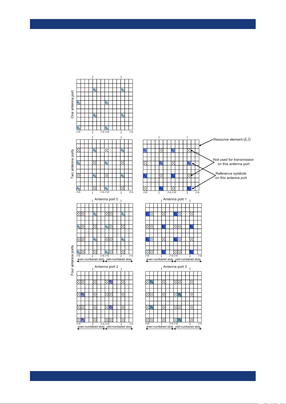
About the EUTRA/LTE optionsEUTRA/LTE/IoT
Introduction to the EUTRA/LTE technology
AP 3). Specific predefined resource elements in the time-frequency domain carry the
reference signal sequence. Besides first reference symbols, there can be a need for
second reference symbols. The different colors in the figure represent the sequences
transmitted from up to four transmit antennas.
Figure 2-9: Downlink reference signal structure (normal cyclic prefix)
28User Manual 1178.8194.02 ─ 09

About the EUTRA/LTE optionsEUTRA/LTE/IoT
Introduction to the EUTRA/LTE technology
The reference signal sequence carries the cell identity. There are 504 unique physical
layer cell identities, grouped into 168 unique physical cell identity groups that contain
three unique identities each. Each reference signal is generated as a pseudo-random
sequence that depends on the physical layer cell identity.
Frequency hopping can be applied to the downlink reference signals. The frequency
hopping pattern has a period of one frame (10 ms).
During cell search, the handset identifies different types of information: symbol and
radio frame timing, frequency, cell identification, overall transmission bandwidth,
antenna configuration, and cyclic prefix length.
Besides the reference signals, synchronization signals are therefore needed during cell
search. EUTRA uses a hierarchical cell search scheme similar to WCDMA. This
means that the synchronization acquisition and the cell group identifier are obtained
from different SYNC signals. Thus, a primary synchronization signal (P-SYNC or PSS)
and a secondary synchronization signal (S-SYNC or SSS) are defined with a predefined structure. They are transmitted on the 72 center subcarriers (around DC subcarrier) within the same predefined slots (twice per 10 ms) on different resource elements, see Figure 2-10. This figure is taken from TS 36.211.
Figure 2-10: P-SYNC and S-SYNC structure (normal CP; 1.25 MHz bandwidth)
As additional help during cell search, a common control physical channel (CCPCH) is
available which carries BCH type of information, e.g. system bandwidth. It is transmitted at predefined time instants on the 72 subcarriers centered on the DC subcarrier.
To enable the UE to support this cell search concept, it was agreed to have a minimum
UE bandwidth reception capability of 20 MHz.
Related settings
See "Synchronization Signal Settings" on page 102.
MBSFN reference signals
MBSFN reference signals are defined fro extended cyclic prefix only. The MBSFN reference signals are transmitted on antenna port 4 (AP 4) and only when the PMCH is
transmitted.
The Figure 2-11 shows the resource elements used by the MBSFN reference signal if
Δf=15 kHz .
29User Manual 1178.8194.02 ─ 09

About the EUTRA/LTE optionsEUTRA/LTE/IoT
Introduction to the EUTRA/LTE technology
Figure 2-11: MBSFN reference signal structure (extended cyclic prefix, carrier spacing 15 KHz)
Related settings
See Chapter 4.2.3, "MBSFN settings", on page 78.
UE-specific reference signal (DMRS)
These reference signals are intended for a specific user and mapped to predefined
PDSCH RBs of this particular user. The resource elements predefined for the UE-specific RS do not overlap with the resource elements reserved for the cell-specific reference signals.
For single-antenna transmission, the UE-specific reference signals are transmitted on
antenna port 5, 7 or 8 (AP 5, AP 7, and AP 8). If a spatial multiplexing is applied, the
UE-specific reference signals are transmitted on antenna ports 7 to 10 (AP 7 to AP 10).
The UE-specific RS are also called demodulation reference signals (DMRS) and are
intended for channel estimation and demodulation instead of the common reference
signals. One typical example of the application of UE-specific RS is the channel estimation and demodulation, if beamforming transmission is used. This is also called
transmission using antenna port 5 (AP 5).
In contrary to the common reference signals that are not precoded, the UE-specific RS
are precoded in the same way as the PDSCH they are mapped to.
See Figure 2-12 and Figure 2-13 for illustration of the mapping of the UE-specific reference signals to the resource elements.
30User Manual 1178.8194.02 ─ 09
 Loading...