

Page 1

R&S®SMBVB-K54/-K86/-K142
IEEE 802.11a/b/g/n, IEEE 802.11ac,
IEEE 802.11ax
User Manual
(;ÜàD2)
1178822002
User Manual
Version 01
Page 2

This document describes the following software options:
●
R&S®SMBVB-K54/-K86/-K142
1423.7824.02, 1423.7924.02, 1423.8114.02
This manual describes firmware version FW 4.30.060.xx and later of the R&S®SMBV100B.
© 2018 Rohde & Schwarz GmbH & Co. KG
Mühldorfstr. 15, 81671 München, Germany
Phone: +49 89 41 29 - 0
Fax: +49 89 41 29 12 164
Email: info@rohde-schwarz.com
Internet: www.rohde-schwarz.com
Subject to change – Data without tolerance limits is not binding.
R&S® is a registered trademark of Rohde & Schwarz GmbH & Co. KG.
Trade names are trademarks of the owners.
1178.8220.02 | Version 01 | R&S®SMBVB-K54/-K86/-K142
The following abbreviations are used throughout this manual: R&S®SMBV100B is abbreviated as R&S SMBVB, R&S®WinIQSIM2
is abbreviated as R&S WinIQSIM2; the license types 02/03/07/11/13/16/12 are abbreviated as xx.
TM
Page 3

R&S®SMBVB-K54/-K86/-K142
Contents
1 Preface.................................................................................................... 7
1.1 About This Manual........................................................................................................ 7
1.2 Documentation Overview............................................................................................. 7
1.2.1 Getting Started Manual................................................................................................... 8
1.2.2 User Manuals and Help...................................................................................................8
1.2.3 Service Manual............................................................................................................... 8
1.2.4 Instrument Security Procedures......................................................................................8
1.2.5 Basic Safety Instructions.................................................................................................8
1.2.6 Data Sheets and Brochures............................................................................................ 9
1.2.7 Release Notes and Open Source Acknowledgment (OSA)............................................ 9
1.2.8 Application Notes, Application Cards, White Papers, etc................................................9
Contents
2 Welcome to the IEEE 802.11 WLAN Digital Standard....................... 10
2.1 Accessing the IEEE 802.11 WLAN Dialog................................................................. 11
2.2 Scope............................................................................................................................11
2.3 Notes on Screenshots................................................................................................ 12
3 About IEEE 802.11 WLAN and Basics................................................13
3.1 Operation Modes.........................................................................................................14
3.2 Signal Generation....................................................................................................... 15
4 WLAN Configuration and Settings..................................................... 16
4.1 General Settings..........................................................................................................16
4.2 Transmit Antenna Setup.............................................................................................20
4.2.1 Antenna and Mapping Setting.......................................................................................20
4.2.2 Transmission Chain Matrix............................................................................................20
4.3 Trigger Settings...........................................................................................................21
4.4 Marker Settings........................................................................................................... 25
4.5 Clock Settings............................................................................................................. 27
4.6 Global Connector Settings.........................................................................................28
4.7 Frame Block Configuration........................................................................................ 29
4.8 PPDU Configuration....................................................................................................34
4.8.1 General Settings........................................................................................................... 35
3User Manual 1178.8220.02 ─ 01
Page 4

R&S®SMBVB-K54/-K86/-K142
4.8.1.1 Stream Settings.............................................................................................................35
4.8.1.2 User Settings.................................................................................................................36
4.8.1.3 Modulation and Coding Scheme................................................................................... 37
4.8.1.4 PSDU Bit Rate (CCK/PBCC)........................................................................................ 39
4.8.2 HE Configuration Settings.............................................................................................40
4.8.2.1 HE General Configuration Settings .............................................................................. 40
4.8.2.2 Additional HE-SIG-A-Fields...........................................................................................43
4.8.2.3 Logging......................................................................................................................... 44
4.8.3 User Configuration........................................................................................................ 45
4.8.4 Data Settings.................................................................................................................48
4.8.4.1 Data Settings.................................................................................................................48
4.8.4.2 Header Settings............................................................................................................ 52
4.9 A-MPDU Settings.........................................................................................................53
Contents
4.10 MAC Header and FCS Configuration for Frame Block............................................ 55
4.10.1 MAC Header and FCS.................................................................................................. 55
4.10.2 802.11 MAC Frame Field.............................................................................................. 56
4.10.3 Beacon Settings............................................................................................................ 60
4.10.3.1 General Beacon Functions............................................................................................60
4.10.3.2 Capability Information Parameters................................................................................62
4.10.3.3 ERP Parameters........................................................................................................... 64
4.10.3.4 HT Capability Information..............................................................................................65
4.10.4 Trigger Frame Settings..................................................................................................66
4.10.4.1 Common Info Field........................................................................................................66
4.10.4.2 User Info Field...............................................................................................................69
4.11 MAC Header HT/HE and VHT Configuration.............................................................71
4.11.1 Common Settings..........................................................................................................72
4.11.2 MAC HT Configuration.................................................................................................. 72
4.11.3 MAC VHT Configuration................................................................................................75
4.11.4 MAC HE Configuration..................................................................................................78
4.12 Spatial Mapping...........................................................................................................79
4.13 Filter / Clipping Settings.............................................................................................82
4.13.1 Filter Settings................................................................................................................ 82
4.13.2 Clipping Settings........................................................................................................... 85
4User Manual 1178.8220.02 ─ 01
Page 5

R&S®SMBVB-K54/-K86/-K142
5 How to Work with the IEEE 802.11 WLAN Option............................. 87
5.1 Generating a Realistic MxN MIMO WLAN 802.11n/ac/p Signal for Receiver Test
under Static Conditions..............................................................................................87
6 Remote-Control Commands............................................................... 89
6.1 Programming Examples............................................................................................. 90
6.1.1 Trigger Settings.............................................................................................................90
6.1.2 Marker Settings............................................................................................................. 91
6.1.3 Clock Settings............................................................................................................... 91
6.2 General Commands.................................................................................................... 92
6.3 Filter/Clipping Settings...............................................................................................96
6.4 Trigger Settings.........................................................................................................101
6.5 Marker Settings......................................................................................................... 106
6.6 Clock Settings............................................................................................................111
Contents
6.7 Antenna Configuration Settings.............................................................................. 111
6.8 Frame Block Configuration...................................................................................... 114
6.9 Frame Configuration Settings..................................................................................120
6.9.1 Frame Block PPDU Configuration ..............................................................................120
6.9.2 HE Configuration.........................................................................................................134
6.9.3 User Configuration...................................................................................................... 139
6.9.4 MPDU Configuration................................................................................................... 142
6.9.5 MAC Header Configuration......................................................................................... 144
6.9.5.1 Common Fields Commands .......................................................................................144
6.9.5.2 MAC Header HT Configuration................................................................................... 151
6.9.5.3 MAC Header VHT Configuration.................................................................................156
6.9.5.4 MAC Header HE Configuration................................................................................... 161
6.9.5.5 Trigger Frame Settings................................................................................................161
6.9.6 Beacon Configuration..................................................................................................163
6.9.6.1 General Beacon Functions..........................................................................................163
6.9.6.2 Capability Information Parameters..............................................................................165
6.9.6.3 ERP Parameters ........................................................................................................ 171
6.9.7 Spatial Mapping Configuration.................................................................................... 172
List of Commands..............................................................................175
Index....................................................................................................182
5User Manual 1178.8220.02 ─ 01
Page 6

R&S®SMBVB-K54/-K86/-K142
Contents
6User Manual 1178.8220.02 ─ 01
Page 7

R&S®SMBVB-K54/-K86/-K142
1 Preface
1.1 About This Manual
This user manual provides all the information specific to the digital standard
IEEE 802.11.
The main focus of this manual is on the provided settings and the tasks required to
generate a signal. The following topics are included:
●
Introduction to and getting familiar with the option
●
About the IEEE 802.11 and basics
Background information on basic terms and principles in the context of the signal
generation
●
IEEE 802.11 configuration and settings
A concise description of all functions and settings available to configure signal generation with their corresponding remote control commands
●
Remote control commands
Remote commands required to configure and perform signal generation in a
remote environment, sorted by tasks
●
List of remote commands
Alphabetical list of all remote commands described in the manual
●
Index
Preface
Documentation Overview
Contents and scope
This description assumes R&S SMBV100B equipped with all availabe options.
Depending on your model and the installed options, some of the functions may not be
available on your instrument.
Notes on screenshots
When describing the functions of the product, we use sample screenshots. These
screenshots are meant to illustrate as much as possible of the provided functions and
possible interdependencies between parameters. The shown values may not represent
realistic usage scenarios.
The screenshots usually show a fully equipped product, that is: with all options installed. Thus, some functions shown in the screenshots may not be available in your particular product configuration.
1.2 Documentation Overview
This section provides an overview of the R&S SMBV100B user documentation. Unless
specified otherwise, you find the documents on the R&S SMBV100B product page at:
7User Manual 1178.8220.02 ─ 01
Page 8

R&S®SMBVB-K54/-K86/-K142
www.rohde-schwarz.com/manual/smbv100b
1.2.1 Getting Started Manual
Introduces the R&S SMBV100B and describes how to set up and start working with the
product. Includes basic operations, typical measurement examples, and general information, e.g. safety instructions, etc. A printed version is delivered with the instrument.
1.2.2 User Manuals and Help
Separate manuals for the base unit and the software options are provided for download:
●
Base unit manual
Contains the description of all instrument modes and functions. It also provides an
introduction to remote control, a complete description of the remote control commands with programming examples, and information on maintenance, instrument
interfaces and error messages. Includes the contents of the getting started manual.
●
Software option manual
Contains the description of the specific functions of an option. Basic information on
operating the R&S SMBV100B is not included.
Preface
Documentation Overview
All user manuals are also available for download or for immediate display on the Internet.
1.2.3 Service Manual
Describes the performance test for checking the rated specifications, module replacement and repair, firmware update, troubleshooting and fault elimination, and contains
mechanical drawings and spare part lists.
The service manual is available for registered users on the global Rohde & Schwarz
information system (GLORIS, https://gloris.rohde-schwarz.com).
1.2.4 Instrument Security Procedures
Deals with security issues when working with the R&S SMBV100B in secure areas. It
is available for download on the Internet.
1.2.5 Basic Safety Instructions
Contains safety instructions, operating conditions and further important information.
The printed document is delivered with the instrument.
8User Manual 1178.8220.02 ─ 01
Page 9

R&S®SMBVB-K54/-K86/-K142
1.2.6 Data Sheets and Brochures
The data sheet contains the technical specifications of the R&S SMBV100B. It also
lists the options and their order numbers and optional accessories.
The brochure provides an overview of the instrument and deals with the specific characteristics.
See www.rohde-schwarz.com/brochure-datasheet/smbv100b
1.2.7 Release Notes and Open Source Acknowledgment (OSA)
The release notes list new features, improvements and known issues of the current
firmware version, and describe the firmware installation.
The open source acknowledgment document provides verbatim license texts of the
used open source software.
See www.rohde-schwarz.com/firmware/smbv100b
Preface
Documentation Overview
1.2.8 Application Notes, Application Cards, White Papers, etc.
These documents deal with special applications or background information on particular topics.
See www.rohde-schwarz.com/application/smbv100b
9User Manual 1178.8220.02 ─ 01
Page 10

R&S®SMBVB-K54/-K86/-K142
2 Welcome to the IEEE 802.11 WLAN Digital
Standard
The R&S SMBV100B-K54/-K86/-K142 are firmware applications that add functionality
to generate signals in accordance with the wireless LAN standards
IEEE 802.11a/b/g/n/ac/p/j/ax.
The option R&S SMBVB-K54 offers signal generation according to IEEE 802.11n, also
legacy modes of IEEE 802.11a/b/g and IEEE 802.11p/j are supported. For
IEEE 802.11ac signal generation option R&S SMBVB-K86 is required and for
IEEE 802.11ax signal generation option R&S SMBVB-K142. At least one
R&S SMBVB-K54 option must be installed on the respective instrument as a prerequisite.
The R&S SMBV100B supports all mandatory and almost all optional features of the
IEEE 802.11 standard.
The following list gives an overview of the main features:
●
Support of up to eight Tx antennas
●
20 MHz and 40 MHz
●
80 MHz and 160 MHz bandwidth with option R&S SMBVB-K86/-K142
●
Support of all three operation modes (Legacy, Mixed Mode, Green Field)
●
Support of all legacy transmission modes (L-10 MHz, L-20 MHz, L-Duplicate, LUpper, L-Lower)
●
Support of all 11n transmission modes (HT-20 MHz, HT-40 MHz, HT-Duplicate, HTUpper, HT-Lower)
●
Support of all 11ac transmission modes with option R&S SMBVB-K86 (VHT-20
MHz, VHT-40 MHz, VHT-80 MHz, VHT-80+80 MHz, VHT-160 MHz)
●
Support of all 11ax transmission modes with option R&S SMBVB-K142 (HE-20
MHz, HE-40 MHz, HE-80 MHz, HE-80+80 MHz, HE-160 MHz)
●
Additional support of the CCK and PBCC frames in accordance with
IEEE 820.11a/b/g standard
●
Support of Space Time Block Coding ( STBC) and Spatial Multiplexing
●
Up to 8 spatial streams in all supported channel widths
●
Multi-User MIMO available with 2 or more total spatial streams
●
Configurable number of spatial streams, space time streams and additional spatial
streams, as well as configurable modulation per spatial stream
●
Support of short guard interval
●
Configurable state of the scramble, interleaver, time domain windowing and channel coding
●
Configurable PPDU, MAC header and FCS
●
Integrated frame block concept for the generation of sequence of cascaded frame
blocks with different configurations and data rates
●
Support of simple diversity and MIMO tests (frequency flat MIMO channel simulation) without additional channel simulator
Welcome to the IEEE 802.11 WLAN Digital Standard
10User Manual 1178.8220.02 ─ 01
Page 11

R&S®SMBVB-K54/-K86/-K142
●
Simulation of real-time MIMO channel condition for instruments equipped with the
fading options R&S SMBVB-K74/-B14(x2)
This user manual contains a description of the functionality that the application provides, including remote control operation.
All functions not discussed in this manual are the same as in the base unit and are
described in the R&S SMBV100B user manual. The latest version is available at:
www.rohde-schwarz.com/manual/SMBV100B
Installation
You can find detailed installation instructions in the delivery of the option or in the
R&S SMBV100B service manual.
2.1 Accessing the IEEE 802.11 WLAN Dialog
Welcome to the IEEE 802.11 WLAN Digital Standard
Scope
To open the dialog with IEEE 802.11 WLAN settings
► In the block diagram of the R&S SMBV100B, select "Baseband > IEEE 802.11".
A dialog box opens that displays the provided general settings.
The signal generation is not started immediately. To start signal generation with the
default settings, select "State > On".
2.2 Scope
Tasks (in manual or remote operation) that are also performed in the base unit in the
same way are not described here.
In particular, it includes:
●
Managing settings and data lists, like storing and loading settings, creating and
accessing data lists, or accessing files in a particular directory.
●
Information on regular trigger, marker and clock signals and filter settings, if appropriate.
●
General instrument configuration, such as checking the system configuration, configuring networks and remote operation
●
Using the common status registers
For a description of such tasks, see the R&S SMBV100B user manual.
11User Manual 1178.8220.02 ─ 01
Page 12

R&S®SMBVB-K54/-K86/-K142
2.3 Notes on Screenshots
When describing the functions of the product, we use sample screenshots. These
screenshots are meant to illustrate as many as possible of the provided functions and
possible interdependencies between parameters. The shown values may not represent
realistic usage scenarios.
The screenshots usually show a fully equipped product, that is: with all options installed. Thus, some functions shown in the screenshots may not be available in your particular product configuration.
Welcome to the IEEE 802.11 WLAN Digital Standard
Notes on Screenshots
12User Manual 1178.8220.02 ─ 01
Page 13

R&S®SMBVB-K54/-K86/-K142
3 About IEEE 802.11 WLAN and Basics
IEEE 802.11n is the extension of the WLAN IEEE 802.11a/g standard to nominal peak
data rates of 600 Mbps. Like IEEE 802.11a/g, IEEE 802.11n is also based on OFDM.
Additionally, IEEE 802.11n uses MIMO technology, up to 40 MHz bandwidth and special coding for increased throughput. The extension towards higher data rates is also
known as high throughput mode (HT mode) of 802.11n, whereas the non-HT mode can
be seen as the part of 802.11n, which is backwards compatible to 802.11a/g.
IEEE 802.11p is another extension to the WLAN IEEE 802.11a/g standard for the
usage of wireless access in vehicular environment, e.g. Car-to-Car (C2C)/ VehicletoVehicle (V2V), intelligent transport systems(ITS).
IEEE 802.11ac further extends 802.11n to nominal peak data rates of 6240.0 Mbps.
Like IEEE 802.11a/g/n, IEEE 802.11ac is also based on OFDM. Additionally, IEE
802.11ac uses MIMO technology, up to 160 MHz bandwidth and special coding for
increased throughput. The extension towards higher data rates is also known as very
high throughput (VHT) mode of 802.11ac.
About IEEE 802.11 WLAN and Basics
IEEE 802.11ax is aimed to improve the user experience and network performance in
dense deployments in the 2.4 and 5 GHz band. It support uplink and downlink multi
user MIMO and up to 160 MHz bandwidth. It is based on OFDM and OFDMA modulation.
A short comparison between the IEEE 802.11 standards is provided in Table 3-1.
Table 3-1: Overview Comparison of 11n, 11ac, and 11ax
Channel Bandwidth
(MHz)
Subcarrier Spacing
(KHz)
Symbol Time (us) 3.2 3.2 12.8
Cyclic Prefix (us) 0.8 0.8, 0.4 0.8, 1.6, 3.2
MU-MIMO No Downlink Uplink and Downlink
Modulation OFDM OFDM OFDM, OFDMA
Data Subcarrier Modulation
Coding BCC (Mandatory)
802.11n 802.11ac 802.11ax
20, 40 20, 40, 80, 80+80, 160 20, 40, 80, 80+80, 160
312.5 312.5 78.125
BPSK, QPSK, 16-QAM,
64-QAM
LDPC (Optional)
*
BPSK, QPSK, 16-QAM,
64-QAM, 256-QAM
BCC (Mandatory)
LDPC (Optional)
BPSK, QPSK, 16-QAM,
64-QAM, 256-QAM,
1024- QAM
BCC (Mandatory)
LDPC (Mandatory)
*
this table is taken from the white paper 1MA222: IEEE 802.11ax Technology Introduc-
tion.
The following application notes also contain information about the different IEEE
802.11 standards.There are available for free downolad on the Rohde & Schwarz website.
13User Manual 1178.8220.02 ─ 01
Page 14
R&S®SMBVB-K54/-K86/-K142
●
1GP94: Generating Signals for WLAN 802.11ac
●
1MA152: Intelligent Transportation Systems Using IEEE 802.11p
●
1MA179: WLAN 802.11n: From SISO to MIMO
●
1MA192: 802.11ac Technology Introduction
●
1MA222: IEEE 802.11ax Technology Introduction
3.1 Operation Modes
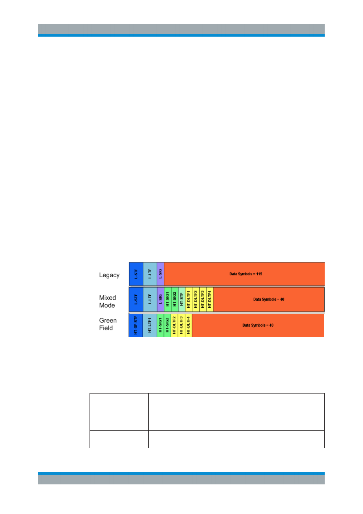
The IEEE 802.11n standard defined the following three operation modes:
●
Legacy mode
This mode is provided for backwards compatibility with the IEEE 802. a/g standard.
The mode is also known as Non-HT mode.
●
Mixed Mode
A legacy preamble and header (L-STF, L-LTF and L-SIG) are wrapping the HT part
of the frame so that the frame is complying with OFDM-PHY and ERP-OFDM-PHY
corresponding to 802.11 a/g respectively.
●
Green Field
In this mode, frames are being transmitted in a new high throughput format that
does not comply with the legacy mode. Green Field is an optional mode.
About IEEE 802.11 WLAN and Basics
Operation Modes
The Figure 3-1 shows the packet formats of the different operation modes that can be
triggered by a device supporting the IEEE 802.11n standard.
Figure 3-1: PLCP packet format for IEEE 802.11
The Table 3-2 gives an overview of the frequency domain operation modes of the
physical layer. Note that the duplicate mode corresponds to repeating the same complex numbers modulating the subcarriers of the upper channel on the lower channel.
Table 3-2: Frequency domain PHY operation
LM Legacy mode as in IEEE 802.11a/g
Also, the CCK and the PBCC frames as in IEEE 802.11b/g
HT-Mode Frequency: 20 MHz and 40 MHz, 1...4 spatial streams (HT Duplicate Mode
included)
Duplicate Non-HT mode IEEE 802.11a OFDM-PHY format, 20 MHz and 40 MHz dual operation, upper
channel rotated by 90˚ relative to lower channel
14User Manual 1178.8220.02 ─ 01
Page 15
R&S®SMBVB-K54/-K86/-K142
Upper mode Non-HT/HT frame in the upper 20 MHz channel
Lower mode Non-HT/HT frame in the lower 20 MHz channel
VHT-Mode Frequency 20 MHz, 40 MHz, 80 MHz, 160 MHz, 1...8 spatial streams (option
HE mode Frequency 20 MHz, 40 MHz, 80 MHz, 160 MHz, 1...8 spatial streams (option
When operating in the OFDM 20 MHz mode, there are 64 subcarriers available; the
migration to 40 MHz mode offers 128 subcarriers with the same frequency spacing of
312.5 KHz. 80 MHz bandwidth is using 256 subcarriers, keeping the original frequency
spacing. With 160 MHz bandwidth 512 subcarriers apply.
For IEEE 802.11ax in the OFDMA frequency allocation, the resource units (RU) may
contain 26, 52, 106, 242, 484 or 996 tones (aka subcarriers) and are in fixed locations.
The tones/subcarriers in the resource units are adjacent and contiguous except in the
middle of the channel where DC null carriers are present.
About IEEE 802.11 WLAN and Basics
Signal Generation
R&S SMBVB-K86 required)
R&S SMBVB-K142 required)
3.2 Signal Generation
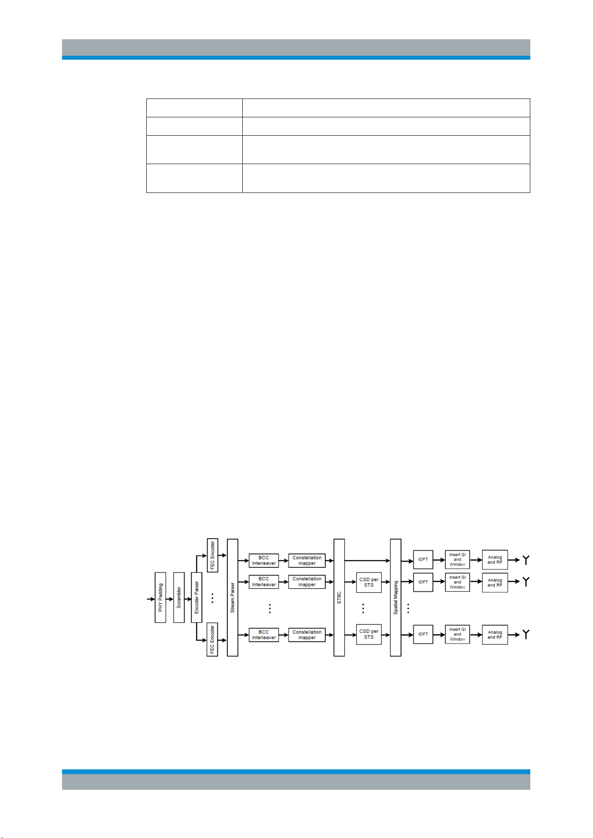
The generation of an IEEE 802.11n/ac/ax signal is done in multiple steps. In high
throughput (HT) and very high throughput (VHT) modes, the data of a single user is
specially coded and transmitted via up to eight Tx antennas.
In this implementation, the mapping of the Tx antennas' signals to the output paths of
the instrument can be configured. This function can be used for the simulation of frequency flat MIMO channel, i.e. one carrier analysis like BER tests for instance. Another
application of the configurable mapping is the possibility to generate a combined signal
from different antennas if there is one path instrument or limited number of baseband
paths.
Refer to Figure 3-2 for an overview of the signal flow for generation of such a signal in
HT mode.
Figure 3-2: IEEE 802.11 n/ac/ax transmission chain
15User Manual 1178.8220.02 ─ 01
Page 16
R&S®SMBVB-K54/-K86/-K142
4 WLAN Configuration and Settings
► To access the IEEE 802.11 WLAN settings, select "Baseband > IEEE 802.11
WLAN".
The remote commands required to define these settings are described in Chapter 6,
"Remote-Control Commands", on page 89.
● General Settings..................................................................................................... 16
● Transmit Antenna Setup......................................................................................... 20
● Trigger Settings.......................................................................................................21
● Marker Settings.......................................................................................................25
● Clock Settings......................................................................................................... 27
● Global Connector Settings...................................................................................... 28
● Frame Block Configuration......................................................................................29
● PPDU Configuration................................................................................................34
● A-MPDU Settings....................................................................................................53
● MAC Header and FCS Configuration for Frame Block........................................... 55
● MAC Header HT/HE and VHT Configuration..........................................................71
● Spatial Mapping...................................................................................................... 79
● Filter / Clipping Settings.......................................................................................... 82
WLAN Configuration and Settings
General Settings
4.1 General Settings
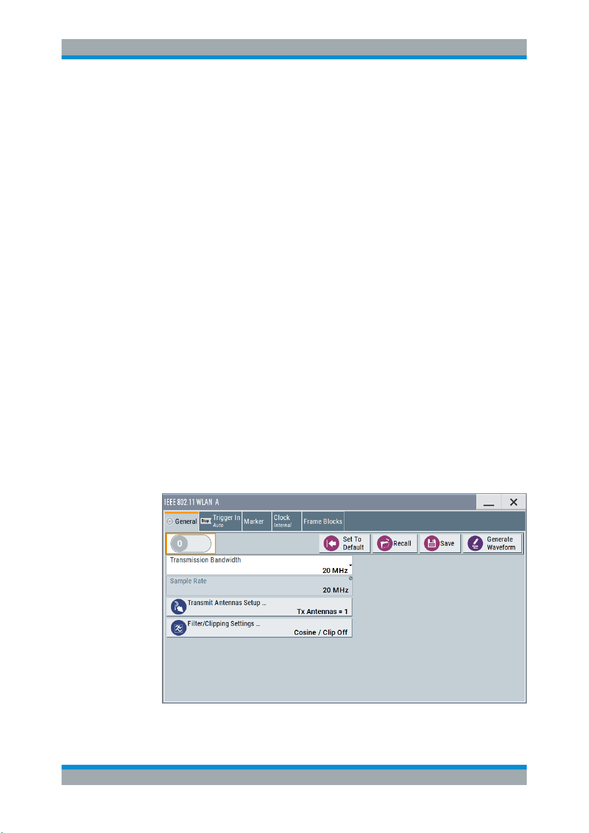
This dialog provides access to the default and the "Save/Recall" settings, and displays
the sample rate.
► To access this dialog select "Baseband > IEEE 802.11 WLAN > General".
This tab comprises the standard general settings.
16User Manual 1178.8220.02 ─ 01
Page 17
R&S®SMBVB-K54/-K86/-K142
State
Activates the standard and deactivates all the other digital standards and digital modulation modes in the same path.
Remote command:
[:SOURce<hw>]:BB:WLNN:STATe on page 95
Set to Default
Calls the default settings. The values of the main parameters are listed in the following
table.
Parameter Value
WLAN Configuration and Settings
General Settings
General parameters
"State" Not affected by "Set to Default"
"Transmission Bandwidth" 20 MHz
"Configure Baseband B from Baseband A" Off
"Tx Antennas" 1
"Filter" Cosine
"Clipping " Off
Frame blocks configuration
"Frame Blocks" 1
"Frame Block Type" DATA
"Frame Blocks State" On
"Physical Mode" Mixed mode
"Tx Mode" HT-20 MHz
"Frames" 1
"Idle Time" 0.1 ms
"Data Source" PN9
TX antenna setup
"Antennas" 1
"Mapping Coordinates" Cartesian
"Output" First set "Baseband", rest is set to Off
"Matrix Elements" ("Real", "Imaginary", "Magnitude",
"Phase")
PPDU configuration
"Spatial Streams" 1
"Space Time Streams" 1
"Extended Spatial Streams" 0
"Space Time Block Coding" inactive
All zero but diagonal = 1
17User Manual 1178.8220.02 ─ 01
Page 18

R&S®SMBVB-K54/-K86/-K142
Parameter Value
WLAN Configuration and Settings
General Settings
Parameter value
"MCS" 1
"Data Rate (Mbps)" 13
"Data Bits Per Symbol" 52
"Stream 1" QPSK
"Channel Coding" BCC
"Coding Rate" ½
"Guard" Long
"Data Length" 1024 bytes
"Number of Data Symbols" 158
"Scrambler" "ON (user init)"
"Scrambler Init" 01
"Interleaver Active" ON
"Service Field" 0000
"Time Domain Windowing Active" On
"Transition Time" 100 ns
"Preamble/Header Active" ON
"Smoothing" ON
Spatial mapping
"Mode" Spatial expansion
"Index k" 20
Remote command:
[:SOURce<hw>]:BB:WLNN:PRESet on page 94
Save/Recall
Accesses the "Save/Recall" dialog, that is the standard instrument function for saving
and recalling the complete dialog-related settings in a file. The provided navigation
possibilities in the dialog are self-explanatory.
The filename and the directory, in which the settings are stored, are user-definable; the
file extension is however predefined.
See also, chapter "File and Data Management" in the R&S SMBV100B user manual.
Remote command:
[:SOURce<hw>]:BB:WLNN:SETTing:CATalog? on page 94
[:SOURce<hw>]:BB:WLNN:SETTing:LOAD on page 95
[:SOURce<hw>]:BB:WLNN:SETTing:STORe on page 95
[:SOURce<hw>]:BB:WLNN:SETTing:DELete on page 94
18User Manual 1178.8220.02 ─ 01
Page 19

R&S®SMBVB-K54/-K86/-K142
Generate Waveform File
With enabled signal generation, triggers the instrument to store the current settings as
an ARB signal in a waveform file. Waveform files can be further processed by the ARB
and/or as a multi-carrier or a multi-segment signal.
The filename and the directory it is stored in are user-definable; the predefined file
extension for waveform files is *.wv.
Remote command:
[:SOURce<hw>]:BB:WLNN:WAVeform:CREate on page 96
Transmission Bandwidth
Selects the transmission bandwidth.
If the system bandwidth is set to 20 MHz, all invalid configurations in the frame blocks
table are set to the default values.
Remote command:
[:SOURce<hw>]:BB:WLNN:BWidth on page 92
Sample Rate
Displays the sample rate of the signal specific for the selected bandwidth.
Remote command:
[:SOURce<hw>]:BB:WLNN:SRATe? on page 100
WLAN Configuration and Settings
General Settings
Transmit Antennas Setup
Accesses the dialog for configuring the TX antennas.
The menu is described in Chapter 4.2, "Transmit Antenna Setup", on page 20.
Remote command:
n.a.
Filter / Clipping Settings
Accesses the dialog for setting baseband filtering and clipping, seeChapter 4.13, "Fil-
ter / Clipping Settings", on page 82.
19User Manual 1178.8220.02 ─ 01
Page 20
R&S®SMBVB-K54/-K86/-K142
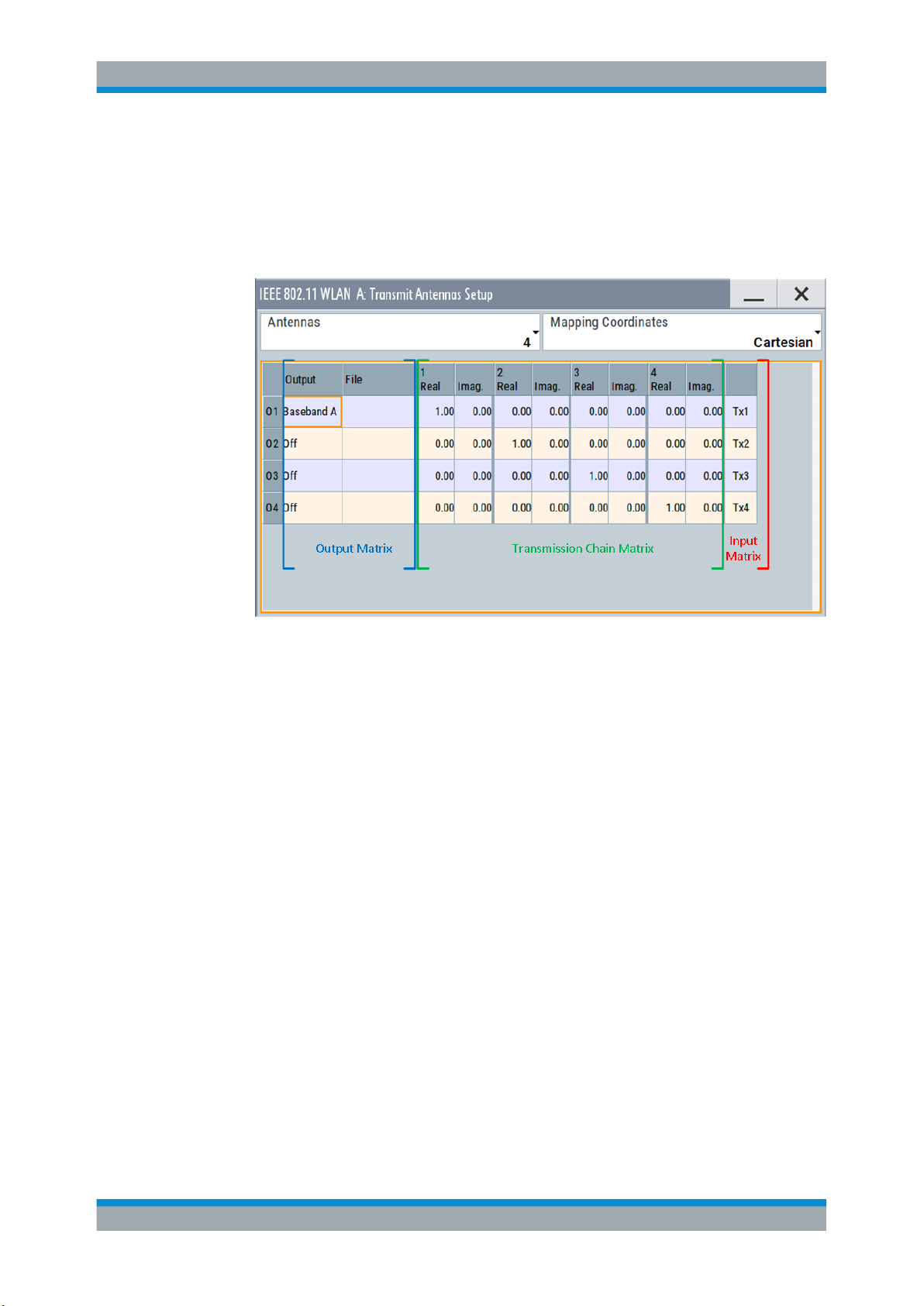
4.2 Transmit Antenna Setup
► To access this dialog select "Baseband > WLAN Standards > IEEE 802.11...> Gen-
eral > Transmit Antennas Setup".
WLAN Configuration and Settings
Transmit Antenna Setup
This dialog is used to map the generated Tx chains to different destinations ("Baseband A/B", "File" or "OFF") and makes it possible to combine different Tx antenna
signals.
4.2.1 Antenna and Mapping Setting
Antennas
Selects the number of transmit antennas to be used.
Remote command:
[:SOURce<hw>]:BB:WLNN:ANTenna:MODE on page 111
Mapping Coordinates
Selects the coordinate system of the transmission chain matrix.
"Cartesian"
"Cylindrical"
Remote command:
[:SOURce<hw>]:BB:WLNN:ANTenna:SYSTem on page 112
Sets the Cartesian coordinates system ("Real", "Imaginary").
Sets the cylindrical coordinates system ("Magnitude", "Phase").
4.2.2 Transmission Chain Matrix
The transmission chain matrix can be used to adjust the channel coefficients.
20User Manual 1178.8220.02 ─ 01
Page 21

R&S®SMBVB-K54/-K86/-K142
During signal calculation, the R&S SMBV100B evaluates the transmission matrix and
takes the phase ratios set into account. However, the power ratio of the antennas is not
considered. To generate a WLAN signal of antennas with different power level, set the
power level of the corresponding path to the desired level in the header display of the
instrument.
Output
Selects the destination of the calculated IQ chains.
"OFF"
"Baseband A/B"
"File"
Remote command:
[:SOURce<hw>]:BB:WLNN:ANTenna:TCHain<ch>:OUTPut:DESTination
on page 112
[:SOURce<hw>]:BB:WLNN:ANTenna:TCHain<ch>:OUTPut:FSELect
on page 112
WLAN Configuration and Settings
Trigger Settings
No mapping takes place.
The IQ chain is output to the selected baseband. Exactly one output
stream can be mapped to a baseband.
The IQ chain is saved in a file.
Real/Magnitude
Enters the value of the real or the magnitude coordinates.
Remote command:
For "Cartesian" mapping coordinates:
[:SOURce<hw>]:BB:WLNN:ANTenna:TCHain<ch>:TX<dir>:REAL on page 112
For "Cylindrical" mapping coordinates:
[:SOURce<hw>]:BB:WLNN:ANTenna:TCHain<ch>:TX<dir>:MAGNitude
on page 113
Imaginary/Phase
Enters the value of the imaginary or the phase coordinates.
Remote command:
For Cartesian mapping coordinates:
[:SOURce<hw>]:BB:WLNN:ANTenna:TCHain<ch>:TX<dir>:IMAGinary
on page 113
For "Cylindrical" mapping coordinates:
[:SOURce<hw>]:BB:WLNN:ANTenna:TCHain<ch>:TX<dir>:PHASe on page 113
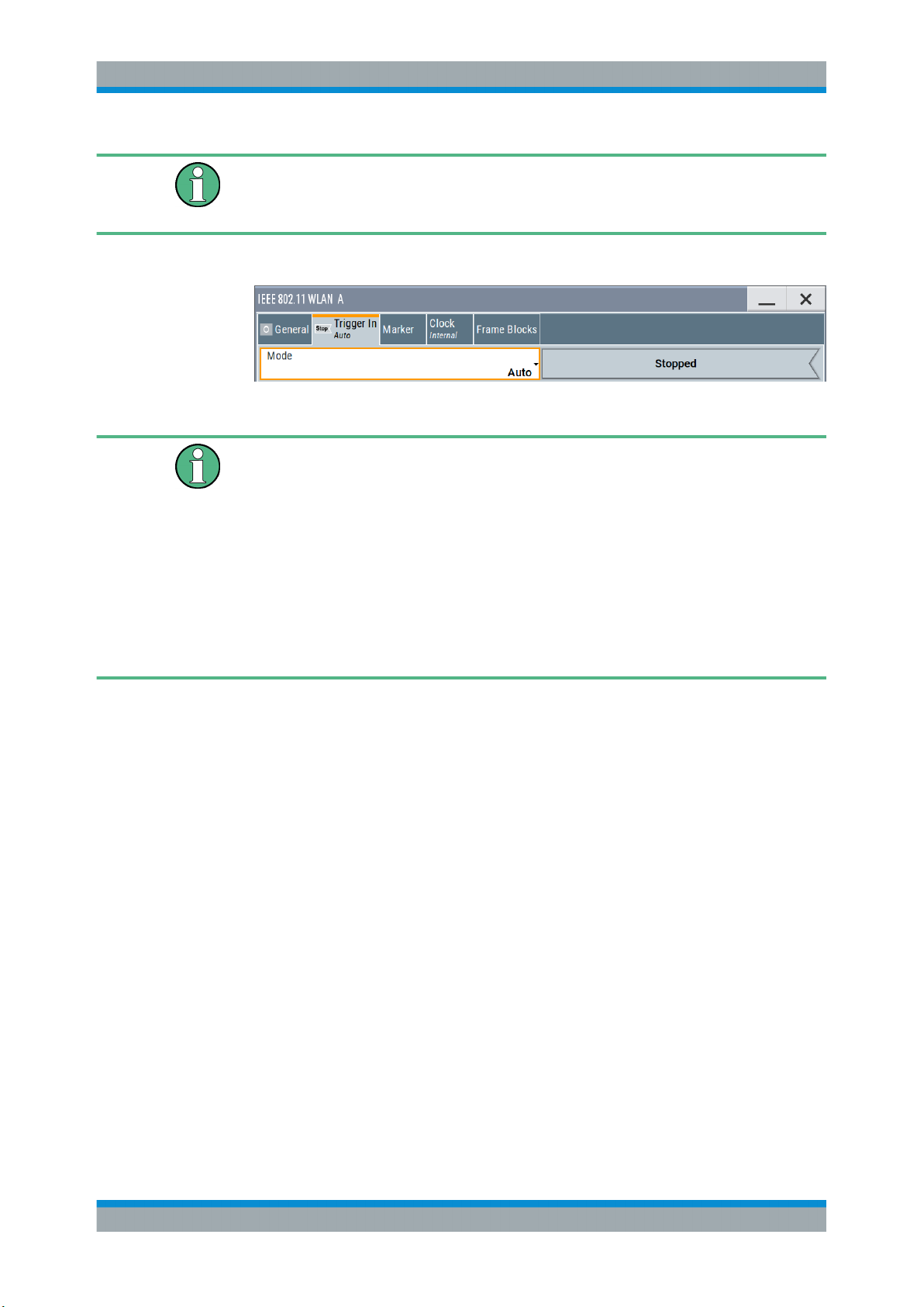
4.3 Trigger Settings
This tab provides access to the settings necessary to select and configure the trigger
and to arm or trigger an internal trigger manually. The current signal generation status
is displayed in the header of the tab together with information on the enabled trigger
mode. As in the "Marker" and "Clock" tabs, this tab provides also access to the settings
of the related connectors.
21User Manual 1178.8220.02 ─ 01
Page 22
R&S®SMBVB-K54/-K86/-K142
This section focuses on the available settings.
For information on how these settings affect the signal, refer to section "Basics on ..."
in the R&S SMBV100B user manual.
► To access this dialog, select "Baseband > IEEE 802.11 WLAN > Trigger In".
This dialog comprises the settings required for configuring the trigger signal.
Routing and enabling a trigger
The provided trigger signals are not dedicated to a particular connector. Trigger signals
can be mapped to one or more User x connectors.
Use the Global Connector Settings to configure the signal mapping, the polarity, the
trigger threshold and the input impedance of the input connectors.
To route and enable a trigger signal, perform the following general steps:
●
Define the signal source and the effect of a trigger event.
Select the "Trigger In > Mode" and "Trigger In > Source".
●
Define the connector where the selected signal is provided.
Use the Global Connector Settings.
WLAN Configuration and Settings
Trigger Settings
Trigger Mode
Selects trigger mode, i.e. determines the effect of a trigger event on the signal generation.
●
"Auto"
The signal is generated continuously.
●
"Retrigger"
The signal is generated continuously. A trigger event (internal or external) causes a
restart.
●
"Armed Auto"
The signal is generated only when a trigger event occurs. Then the signal is generated continuously.
An "Arm" stops the signal generation. A subsequent trigger event (internal with or
external) causes a restart.
●
"Armed Retrigger"
The signal is generated only when a trigger event occurs. Then the signal is generated continuously. Every subsequent trigger event causes a restart.
An "Arm" stops signal generation. A subsequent trigger event (internal with or
external) causes a restart.
●
"Single"
The signal is generated only when a trigger event occurs. Then the signal is generated once to the length specified at "Signal Duration".
Every subsequent trigger event (internal or external) causes a restart.
22User Manual 1178.8220.02 ─ 01
Page 23

R&S®SMBVB-K54/-K86/-K142
Remote command:
[:SOURce<hw>]:BB:WLNN[:TRIGger]:SEQuence on page 105
Signal Duration Unit
Defines the unit for describing the length of the signal sequence to be output in the
"Single" trigger mode.
Remote command:
[:SOURce<hw>]:BB:WLNN:TRIGger:SLUNit on page 104
Trigger Signal Duration
Enters the length of the signal sequence to be output in the "Single" trigger mode.
Use this parameter to output part of the signal deliberately, an exact sequence of the
signal, or a defined number of repetitions of the signal.
Remote command:
[:SOURce<hw>]:BB:WLNN:TRIGger:SLENgth on page 103
Running/Stopped
With enabled modulation, displays the status of signal generation for all trigger modes.
●
"Running"
The signal is generated; a trigger was (internally or externally) initiated in triggered
mode.
●
"Stopped"
The signal is not generated and the instrument waits for a trigger event.
Remote command:
[:SOURce<hw>]:BB:WLNN:TRIGger:RMODe? on page 103
WLAN Configuration and Settings
Trigger Settings
Arm
Stops the signal generation until subsequent trigger event occurs.
Remote command:
[:SOURce<hw>]:BB:WLNN:TRIGger:ARM:EXECute on page 102
Execute Trigger
For internal trigger source, executes trigger manually.
Remote command:
[:SOURce<hw>]:BB:WLNN:TRIGger:EXECute on page 102
Trigger Source
The following sources of the trigger signal are available:
●
"Internal"
The trigger event is executed manually by the "Execute Trigger".
●
"External Global Trigger"
The trigger event is the active edge of an external trigger signal provided and configured at the User x connectors.
●
"Baseband Sync In"
In master-slave mode, slave instruments are triggered by the active edge of the
synchronization signal.
23User Manual 1178.8220.02 ─ 01
Page 24
R&S®SMBVB-K54/-K86/-K142
Remote command:
[:SOURce<hw>]:BB:WLNN:TRIGger:SOURce on page 104
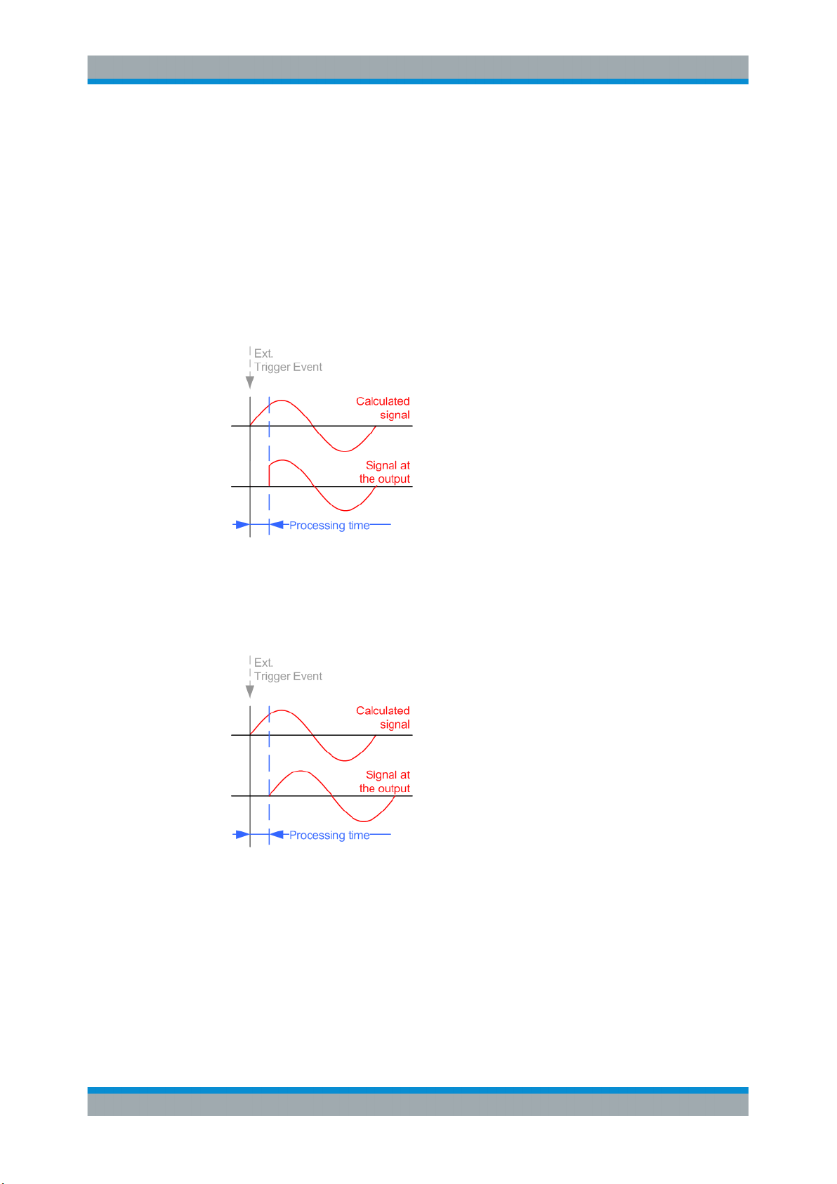
Sync. Output to External Trigger/Sync. Output to Trigger
Enables signal output synchronous to the trigger event.
●
"On"
Corresponds to the default state of this parameter.
The signal calculation starts simultaneously with the trigger event. Because of the
processing time of the instrument, the first samples are cut off and no signal is output. After elapsing of the internal processing time, the output signal is synchronous
to the trigger event.
WLAN Configuration and Settings
Trigger Settings
●
"Off"
The signal output begins after elapsing of the processing time. Signal output starts
with sample 0. The complete signal is output.
This mode is recommended for triggering of short signal sequences. Short sequences are sequences with signal duration comparable with the processing time of the
instrument.
In master-slave mode, this setting ensures that once achieved, synchronization is not
lost if the baseband signal sampling rate changes.
Remote command:
[:SOURce<hw>]:BB:WLNN:TRIGger:EXTernal:SYNChronize:OUTPut
on page 103
External Trigger Inhibit
Applies for external trigger signal.
24User Manual 1178.8220.02 ─ 01
Page 25
R&S®SMBVB-K54/-K86/-K142
Sets the duration with that any following trigger event is suppressed. In "Retrigger"
mode, for example, a new trigger event does not cause a restart of the signal generation until the specified inhibit duration does not expire.
For more information, see chapter "Basics" in the R&S SMBV100B user manual.
Remote command:
[:SOURce<hw>]:BB:WLNN:TRIGger[:EXTernal]:INHibit on page 105
Trigger Delay
Delays the trigger event of the signal from:
●
The external trigger source
Use this setting to:
●
Synchronize the instrument with the device under test (DUT) or other external devices
●
Compensate delays and align the signal generation start in multi-instrument setup
For more information, see chapter "Basics on ..." in the R&S SMBV100B user manual.
Remote command:
[:SOURce<hw>]:BB:WLNN:TRIGger[:EXTernal]:DELay on page 105
WLAN Configuration and Settings
Marker Settings
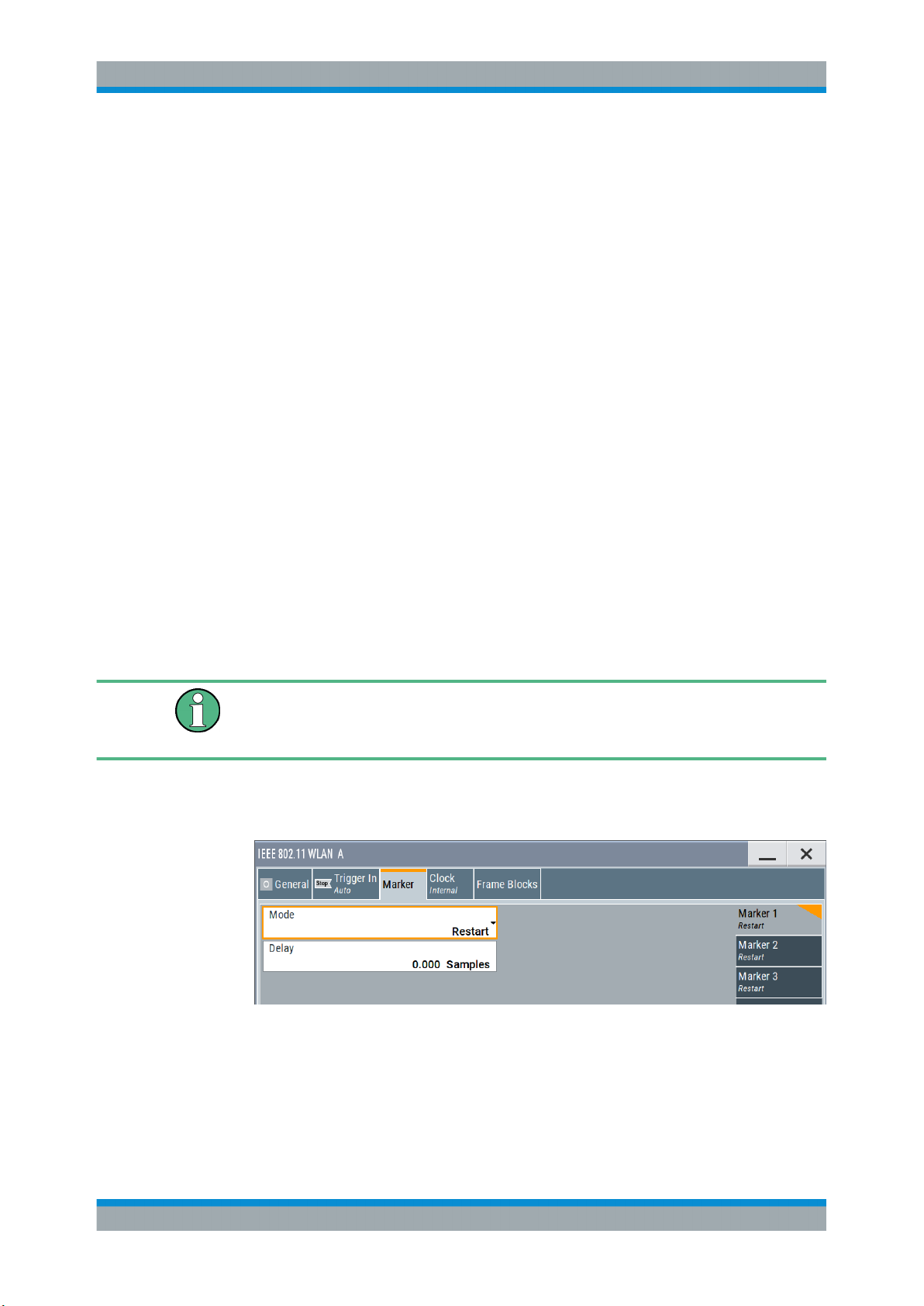
4.4 Marker Settings
This tab provides access to the settings necessary to select and configure the marker
output signal, like the marker mode or marker delay settings.
This section focuses on the available settings.
For information on how these settings affect the signal, refer to section "Basics on ..."
in the R&S SMBV100B user manual.
Access:
► Select "Baseband > IEEE 802.11 WLAN > Marker".
This dialog comprises the settings required for configuring the marker mode and
the marker delay.
25User Manual 1178.8220.02 ─ 01
Page 26

R&S®SMBVB-K54/-K86/-K142
Routing and enabling a marker
The provided marker signals are not dedicated to a particular connector. They can be
mapped to one or more User x connectors.
To route and enable a marker signal, perform the following general steps:
●
Define the shape of the generated marker, i.e. select the "Marker > Mode".
●
Define the connector where the selected signal is provided.
Use the Global Connector Settings.
Marker Mode
Marker configuration for up to 3 markers. The settings are used to select the marker
mode defining the shape and periodicity of the markers. The contents of the dialog
change with the selected marker mode; the settings are self-explanatory.
"Restart"
"Frame Block"
Remote command:
[:SOURce<hw>]:BB:WLNN:TRIGger:OUTPut<ch>:FBINdex on page 108
WLAN Configuration and Settings
Marker Settings
A marker signal is generated at the start of each signal sequence
(period = all frame blocks).
"Number of Frame Blocks" = 1, that is, a marker signal is generated
at the start of each frame block. Otherwise a specific frame block
index is given and the whole frame block is marked.
"Frame"
Remote command:
[:SOURce<hw>]:BB:WLNN:TRIGger:OUTPut<ch>:FINDex on page 108
"Frame Active Part / Frame Inactive Part"
Remote command:
[:SOURce<hw>]:BB:WLNN:TRIGger:OUTPut<ch>:FESHift on page 109
[:SOURce<hw>]:BB:WLNN:TRIGger:OUTPut<ch>:RESHift on page 109
"Number of Frame Blocks" = 1, that is, a marker signal is generated
at the start of each frame in the single frame block. Otherwise, the
frame block and frame index are entered and the specific frame is
masked.
A marker signal is generated to mark every active part of each frame.
The active data transfer part (PPDU) of a frame period is marked with
high, the inactive part (idle time) with low. This marker can be used to
decrease the carrier leakage during inactive signal parts by feeding it
into the pulse modulator.
Otherwise, the frame block and frame index are entered and the
active part of the specific frame is masked.
The parameters "Rising Edge Shift / Falling Edge Shift" open when
"Frame Active Part" or "Frame Inactive Part" is selected.
They shift the rising/falling edge of the marker the specified number
of samples. Negative values result in a shift back of the marker edge.
26User Manual 1178.8220.02 ─ 01
Page 27
R&S®SMBVB-K54/-K86/-K142
WLAN Configuration and Settings
Clock Settings
"Pulse"
Remote command:
[:SOURce<hw>]:BB:WLNN:TRIGger:OUTPut<ch>:PULSe:DIVider on page 109
[:SOURce<hw>]:BB:WLNN:TRIGger:OUTPut<ch>:PULSe:FREQuency?
on page 110
"Pattern"
Remote command:
[:SOURce<hw>]:BB:WLNN:TRIGger:OUTPut<ch>:PATTern on page 109
"ON/OFF Ratio"
Remote command:
[:SOURce<hw>]:BB:WLNN:TRIGger:OUTPut<ch>:ONTime on page 108
[:SOURce<hw>]:BB:WLNN:TRIGger:OUTPut<ch>:OFFTime on page 108
A regular marker signal is generated. The clock frequency is defined
by entering a divider. The frequency is derived by dividing the chip
rate by the divider. The input box for the divider opens when "Pulse"
is selected, and the resulting pulse frequency is displayed below it.
A marker signal that is defined by a bit pattern is generated. The pattern has a maximum length of 32 bits.
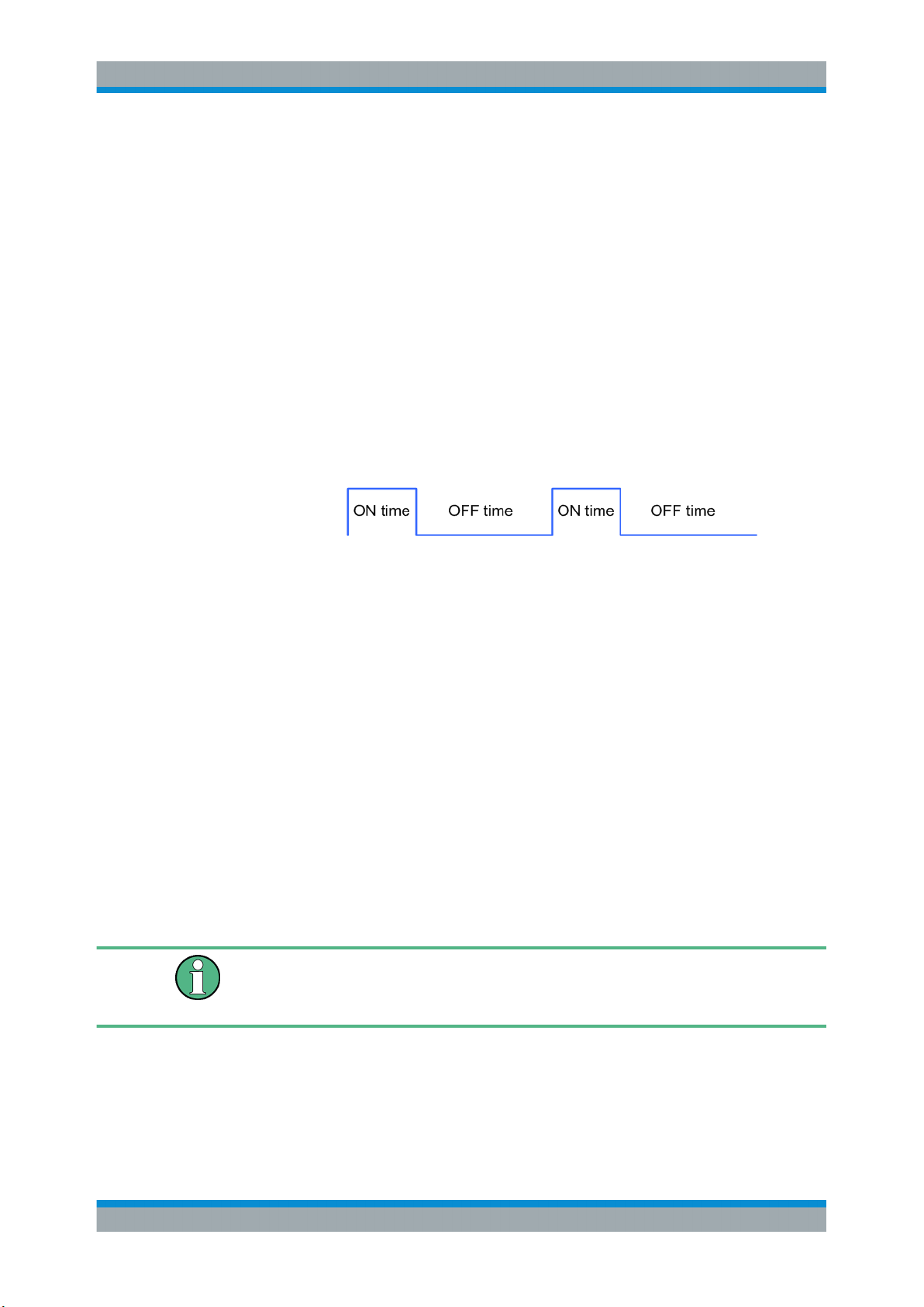
A regular marker signal that is defined by an ON/OFF ratio is generated. A period lasts one ON and OFF cycle.
Remote command:
[:SOURce<hw>]:BB:WLNN:TRIGger:OUTPut<ch>:MODE on page 106
Marker x Delay
Delays the marker signal at the marker output relative to the signal generation start.
Variation of the parameter "Marker x Delay" causes signal recalculation.
Remote command:
[:SOURce<hw>]:BB:WLNN:TRIGger:OUTPut<ch>:DELay on page 110
4.5 Clock Settings
This tab provides access to the settings necessary to select and configure the clock
signal, like the clock source and clock mode.
This section focuses on the available settings.
For information on how these settings affect the signal, refer to section "Basics on ..."
in the R&S SMBV100B user manual.
► To access this dialog, select "Baseband > IEEE 802.11 WLAN > Clock".
27User Manual 1178.8220.02 ─ 01
Page 28
R&S®SMBVB-K54/-K86/-K142
This dialog comprises the settings required for configuring the clock signal.
Defining the Clock
The provided clock signals are not dedicated to a particular connector. They can be
mapped to one or more User x connectors.
Use the Global Connector Settings to configure the signal mapping, the polarity, the
trigger threshold, and the input impedance of the input connectors.
To route and enable a trigger signal, perform the following general steps:
●
Define the signal source, that is select the "Clock > Source".
●
Define the connector where the selected signal is provided.
Use the Global Connector Settings.
WLAN Configuration and Settings
Global Connector Settings
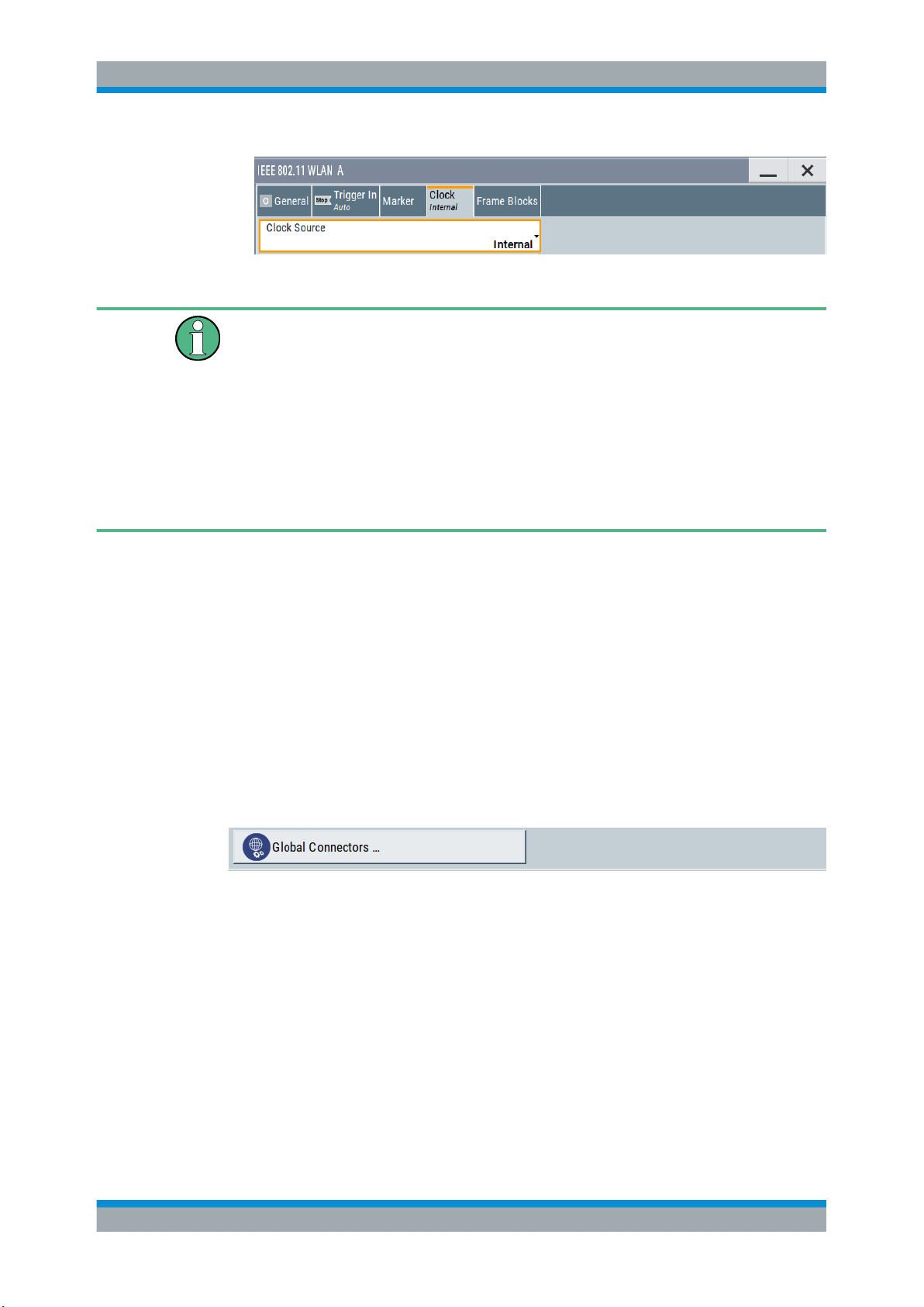
Clock Source
Selects the clock source.
●
"Internal"
The instrument uses its internal clock reference.
Remote command:
[:SOURce<hw>]:BB:WLNN:CLOCk:SOURce on page 111
4.6 Global Connector Settings
Each of the "Trigger In", "Marker" and "Clock" dialogs as well as the "Trigger Marker
Clock" dialog provides a quick access to the related connector settings.
For more information, refer to the description R&S SMBV100B user manual, section
"Global Connector Settings".
28User Manual 1178.8220.02 ─ 01
Page 29
R&S®SMBVB-K54/-K86/-K142
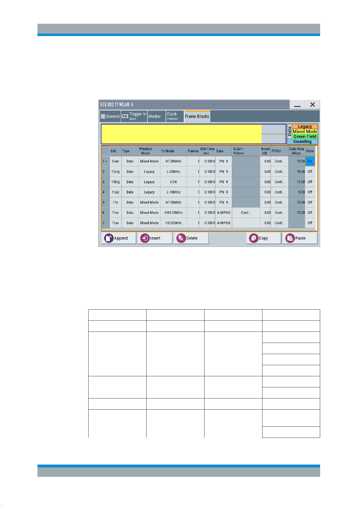
4.7 Frame Block Configuration
► To access this dialog select "Baseband > IEEE 802.11 WLAN > Frame Blocks".
WLAN Configuration and Settings
Frame Block Configuration
This tab comprises the settings to select and configure a frame block.
Standard
Selects the IEEE 802.11 WLAN standard. After you have set your standard only the
settings for this standard relevant "Type", "Physical Mode" and "Tx Mode" are available, see Table 4-1.
Table 4-1: Availability "Standard", "Type", "Physical Mode", "TxMode"
Standard Type Physical mode Txmode
User all all all
11a/g Data/ Beacon/ Trigger Legacy L-20MHz
11b/g Data/ Beacon/ Trigger Legacy CCK
11p/j Data/ Beacon/ Trigger Legacy L-10MHz
11n Data/ Sounding/Beacon/
Trigger
Mixed Mode/ Green
Field
L-Duplicate
L-Upper
L-Lower
PBCC
HT-20MHz
HT-40MHz
29User Manual 1178.8220.02 ─ 01
Page 30
R&S®SMBVB-K54/-K86/-K142
WLAN Configuration and Settings
Frame Block Configuration
11ac Data/ Sounding/ Beacon/
Trigger
11ax Data/ Trigger Mixed Mode HE-20MHz
Mixed Mode VHT-20MHz
HT-Duplicate
HT-Upper
HT-Lower
VHT-40MHz
VHT-80MHz
VHT-80 + 80 MHz
VHT-160MHz
HE-40MHz
HE-80MHz
HE-80 + 80MHz
HE-160MHz
Remote command:
[:SOURce<hw>]:BB:WLNN:FBLock<ch>:STANdard on page 117
Type
Selects the PPDU type.
"Data"
"Sounding"
Only "Data Long Training" fields are used to probe the channel.
Staggered preambles are used to probe additional dimension of the
MIMO channel.
"Type > Sounding" is not available for "Physical Mode > Legacy".
"Beacon"
A frame of type "Beacon" contains all the information about a network, for example the beacon interval, capability information and the
IBSS parameter set. The access point (AP) of a service set periodically transmits the beacon frame to establish and maintain the network.
Remote command:
[:SOURce<hw>]:BB:WLNN:FBLock<ch>:TYPE on page 119
Physical Mode
Selects the preamble design.
For "Physical Mode > Legacy", only "Type > Data" is available.
From 80 MHz transmission bandwidth in the frame block "Type > Data" you can only
operate in "Physical Mode > Mixed Mode".
Note: "Physical Mode > Mixed Mode" transmissions can be detected by a physical
layer transceiver of 802.11a/g OFDM, MAC FCS would however fail.
"Legacy"
Compatible with 802.11a/g OFDM devices. Also, CCK/PBCC frames
as defined in IEEE 802.11b/g are supported.
This mode applies to "Cylindrical" mapping coordinates.
30User Manual 1178.8220.02 ─ 01
Page 31

R&S®SMBVB-K54/-K86/-K142
WLAN Configuration and Settings
Frame Block Configuration
"Mixed Mode"
For High Throughput (HT), Very High Throughput (VHT) , High Efficiency (HE) and 802.11a/g OFDM devices.
"Green Field"
For HT networks only.
Remote command:
[:SOURce<hw>]:BB:WLNN:FBLock<ch>:PMODe on page 117
Tx Mode
Sets the Tx mode.
The available Tx modes depend on the physical mode (see table below).
Type Physical
mode
Data/ Trigger Legacy L-10MHz X X X X
Tx mode Transmission bandwidth
20 MHz 40 MHz 80 MHz 160 MHz
L-20MHz X X X X
L-Duplicate - X X X
L-Upper - X X X
L-Lower - X X X
CCK X X X X
PBCC X X X X
Data/ Trigger Mixed Mode HT-20MHz X X X X
HT-40MHz - X X X
HT-Duplicate - X X X
HT-Upper - X X X
HT-Lower - X X X
VHT-20MHz X X X X
VHT-40MHz - X X X
VHT-80MHz - - X X
VHT-80+80MHz - - X X
VHT-160MHz - - - X
HE-20MHz x x x x
HE-40MHz - x x x
HE-80MHz - - x x
HE-80 + 80MHz - - x x
HE-160MHz - - - x
Data Green Field HT-20MHz X X X X
HT-40MHz - X X X
HT-Duplicate - X X X
31User Manual 1178.8220.02 ─ 01
Page 32

R&S®SMBVB-K54/-K86/-K142
WLAN Configuration and Settings
Frame Block Configuration
Type Physical
mode
Sounding Mixed Mode HT-20MHz X X X X
Sounding Green Field HT-20MHz X X X X
Tx mode Transmission bandwidth
20 MHz 40 MHz 80 MHz 160 MHz
HT-Upper - X X X
HT-Lower - X X X
HT-40MHz - X X X
HT-Duplicate - X X X
HT-Upper - X X X
HT-Lower - X X X
VHT-20MHz X X X X
VHT-40MHz - X X X
VHT-80MHz - - X X
VHT-80+80MHz - - X X
VHT-160MHz - - - X
HT-40MHz - X X X
HT-Duplicate - X X X
HT-Upper - X X X
HT-Lower - X X X
Beacon Legacy L-10MHz X X X X
L-20MHz X X X X
L-Duplicate - X X X
L-Upper - X X X
L-Lower - X X X
CCK X X X X
PBCC X X X X
Remote command:
[:SOURce<hw>]:BB:WLNN:FBLock<ch>:TMODe on page 118
Frames
Sets the number of frames to be transmitted in the current frame block.
Remote command:
[:SOURce<hw>]:BB:WLNN:FBLock<ch>:FCOunt on page 115
Idle Time / ms
Sets the time interval separating two frames in this frame block.
32User Manual 1178.8220.02 ─ 01
Page 33

R&S®SMBVB-K54/-K86/-K142
Remote command:
[:SOURce<hw>]:BB:WLNN:FBLock<ch>:ITIMe on page 117
Data
Selects the data source.
For "Std > 11ax", only the "A-MPDU" data source is available.
The following standard data sources are available:
●
"All 0, All 1"
An internally generated sequence containing 0 data or 1 data.
●
"PNxx"
An internally generated pseudo-random noise sequence.
●
"Pattern"
An internally generated sequence according to a bit pattern.
Use the "Pattern" box to define the bit pattern.
●
"Data List/Select DList"
A binary data from a data list, internally or externally generated.
Select "Select DList" to access the standard "Select List" dialog.
– Select the "Select Data List > navigate to the list file *.dm_iqd > Select" to
select an existing data list.
– Use the "New" and "Edit" functions to create internally new data list or to edit
an existing one.
– Use the standard "File Manager" function to transfer external data lists to the
instrument.
See also:
●
Section "Modulation Data" in the R&S SMBV100B user manual.
●
Section "File and Data Management" in the R&S SMBV100B user manual.
●
Section "Data List Editor" in the R&S SMBV100B user manual
WLAN Configuration and Settings
Frame Block Configuration
Remote command:
[:SOURce<hw>]:BB:WLNN:FBLock<ch>:DATA on page 115
[:SOURce<hw>]:BB:WLNN:FBLock<ch>:DATA:PATTern on page 116
[:SOURce<hw>]:BB:WLNN:FBLock<ch>:DATA:DSELection on page 116
Boost /dB
Assigns a specific RMS power boost/attenuation to the corresponding frame block
modulation.
The power level of a frame block modulation is calculated as sum of the power boost
and the power level set in the header of the instrument.
Note: At least one frame block should have a power boost set to a 0 dB value for this
gated power mode functionality to work properly.
Remote command:
[:SOURce<hw>]:BB:WLNN:FBLock<ch>:BOOSt on page 114
PPDU
Calls the dialog for PPDU configuration of the frame blocks.
The dialog is described in Chapter 4.8, "PPDU Configuration", on page 34.
Remote command:
n.a.
33User Manual 1178.8220.02 ─ 01
Page 34

R&S®SMBVB-K54/-K86/-K142
Data Rate/Mbps
Indicates the PPDU data rate.
Remote command:
[:SOURce<hw>]:BB:WLNN:FBLock<ch>:DATA:RATE? on page 116
[:SOURce<hw>]:BB:WLNN:FBLock<ch>[:USER<di>]:DATA:RATE? on page 123
State
Enables the corresponding frame block for transmission.
Remote command:
[:SOURce<hw>]:BB:WLNN:FBLock<ch>:STATe on page 118
Append
Adds a default frame block behind the selected frame block.
Remote command:
[:SOURce<hw>]:BB:WLNN:FBLock:APPend on page 93
Insert
Adds a default frame block before the selected frame block.
Remote command:
[:SOURce<hw>]:BB:WLNN:FBLock<ch>:INSert on page 93
WLAN Configuration and Settings
PPDU Configuration
Delete
Deletes the selected frame block.
Remote command:
[:SOURce<hw>]:BB:WLNN:FBLock<ch>:DELete on page 93
Copy
Copies the selected frame block.
Remote command:
[:SOURce<hw>]:BB:WLNN:FBLock<ch>:COPY on page 93
Paste
Pastes the copied frame block behind the selected frame block.
Remote command:
[:SOURce<hw>]:BB:WLNN:FBLock<ch>:PASTe on page 93
4.8 PPDU Configuration
Access:
► Select "Frame Blocks > PPDU > Config...".
In this dialog, the mode, the time shifts and the transmit parameters can be configured.
34User Manual 1178.8220.02 ─ 01
Page 35

R&S®SMBVB-K54/-K86/-K142
The parameters available for configuration depend on the selected "Type", "Physical Layer" and "Tx Mode".
4.8.1 General Settings
This dialog comprises the settings for the configuration of the stream settings, the modulation and coding scheme and the PSDU bit rate. The parameters available for configuration depend on the selected "Type", "Physical Layer" and "Tx Mode".
4.8.1.1 Stream Settings
1. To access this dialog select "Frame Blocks > PPDU > Config...".
2. Select "General > Stream Settings".
WLAN Configuration and Settings
PPDU Configuration
Provided are the following settings:
Spatial Streams
Enters the number of the spatial streams. For "Physical Mode > Legacy", only the
value 1 is valid. For "Tx Mode > HT-Duplicate", only the value 1 is valid. In all other
cases, the number of spatial streams depends on the number of antennas configured
in the "TX Antenna Setup" window.
Remote command:
[:SOURce<hw>]:BB:WLNN:FBLock<ch>:SSTReam on page 132
Space Time Streams
Enters the number of the space time streams. This value depends on the setting in the
"Spatial Streams" field. Changing the number of the spatial streams immediately
changes the value of the "Space Time Streams" to the same value.
Remote command:
[:SOURce<hw>]:BB:WLNN:FBLock<ch>:STSTream on page 133
Extended Spatial Streams
Enters the value of the extended spatial streams. This field is active for "Type > Sounding" only to probe additional dimensions of the channel.
Remote command:
[:SOURce<hw>]:BB:WLNN:FBLock<ch>:ESSTream on page 124
35User Manual 1178.8220.02 ─ 01
Page 36

R&S®SMBVB-K54/-K86/-K142
Multi User MIMO
Activates multi user MIMO. This function applies to "Spatial Streams">1.
Remote command:
[:SOURce<hw>]:BB:WLNN:FBLock<ch>:MUMimo:STATe on page 126
Segment
(available only for "Tx Mode > VHT-80+80 MHz")
In "Tx Mode > VHT-80+80 MHz", one of the two segments can be selected with transmission bandwidth 80 MHz or 160 MHz. Both segments can be only generated with
bandwidth 160 MHz.
Remote command:
[:SOURce<hw>]:BB:WLNN:FBLock<ch>:SEGMent on page 131
Space Time Block Coding
Displays the status of the space time block coding.
Remote command:
[:SOURce<hw>]:BB:WLNN:FBLock<ch>:STBC:STATe? on page 132
WLAN Configuration and Settings
PPDU Configuration
4.8.1.2 User Settings
To access this dialog:
1. In the "Frame Blocks" dialog, select "Std. > 11ac".
2. Open the "PPDU > Conf.." dialog.
3. Select "Spatial Streams " > 1.
4. Select "Multi User MIMO > ON".
This section contains the parameters for selecting and configuring signal generation of multiple users.
Provided are the following settings:
36User Manual 1178.8220.02 ─ 01
Page 37

R&S®SMBVB-K54/-K86/-K142
User Index
Defines the currently generated user. For "Multi User MIMO > Active", only one user
can be generated at a time. This parameter selects the generated one out of four available users.
Remote command:
[:SOURce<hw>]:BB:WLNN:FBLock<ch>:UINDex on page 134
Multi User MIMO Settings Table
Sets the user-defined parameters for all available users.
●
User index
A maximum of four users are supported
●
N_STS
Number of space time streams for each user
●
Group ID
Group ID for each user
Remote command:
[:SOURce<hw>]:BB:WLNN:FBLock<ch>:MU<st0>:NSTS on page 126
[:SOURce<hw>]:BB:WLNN:FBLock<ch>:MU<st0>:GID on page 126
WLAN Configuration and Settings
PPDU Configuration
4.8.1.3 Modulation and Coding Scheme
1. To access this dialog select "Frame Blocks > PPDU > Config...".
2. Select "General > MCS Configuration".
Provided are the following settings:
MCS
Selects the modulation and coding scheme for all spatial streams.
Remote command:
[:SOURce<hw>]:BB:WLNN:FBLock<ch>:MCS on page 125
[:SOURce<hw>]:BB:WLNN:FBLock<ch>[:USER<di>]:MCS on page 125
Data Rate/Mbps
Indicates the PPDU data rate.
37User Manual 1178.8220.02 ─ 01
Page 38

R&S®SMBVB-K54/-K86/-K142
Remote command:
[:SOURce<hw>]:BB:WLNN:FBLock<ch>:DATA:RATE? on page 116
[:SOURce<hw>]:BB:WLNN:FBLock<ch>[:USER<di>]:DATA:RATE? on page 123
Data Bits Per Symbol
Displays the number of data bits sent by an OFDM symbol on all spatial streams.
Remote command:
[:SOURce<hw>]:BB:WLNN:FBLock<ch>:DATA:BPSymbol? on page 122
[:SOURce<hw>]:BB:WLNN:FBLock<ch>[:USER<di>]:DATA:BPSymbol?
on page 122
Stream n
Selects the modulation used for the selected spatial stream.
Remote command:
[:SOURce<hw>]:BB:WLNN:FBLock<ch>:MODulation<st> on page 126
[:SOURce<hw>]:BB:WLNN:FBLock<ch>[:USER<di>]:MODulation<st>
on page 126
WLAN Configuration and Settings
PPDU Configuration
Channel Coding
Selects the channel coding.
"Off"
"BCC"
"LDPC"
Remote command:
[:SOURce<hw>]:BB:WLNN:FBLock<ch>:CODing:TYPE on page 122
[:SOURce<hw>]:BB:WLNN:FBLock<ch>[:USER<di>]:CODing:TYPE
on page 122
Encoders
Displays the number of encoders to be used. This value depends on the data rate. For
data rate ≤ 300 mps, this value is 1. Otherwise, the number of encoders is 2.
Remote command:
[:SOURce<hw>]:BB:WLNN:FBLock<ch>:CODing:ENCoder? on page 121
[:SOURce<hw>]:BB:WLNN:FBLock<ch>[:USER<di>]:CODing:ENCoder?
on page 121
Cod Rate
Selects the coding rate.
Remote command:
[:SOURce<hw>]:BB:WLNN:FBLock<ch>:CODing:RATE on page 122
[:SOURce<hw>]:BB:WLNN:FBLock<ch>[:USER<di>]:CODing:RATE
on page 122
No channel coding is used.
Binary convolution code
Low density parity check. This is an optional coding for the
IEEE 802.11ac and IEEE 802.11n standards. Available only for "Tx
Mode > HT.../VHT...".
Guard
Selects which guard interval is used for the OFDM guard.
38User Manual 1178.8220.02 ─ 01
Page 39

R&S®SMBVB-K54/-K86/-K142
In "Physical Mode > Green Field /Legacy" only long guard intervals are possible. In this
case, the field is read-only.
The values "0.8µs", "1.6 µs" and "3.2 µs" are available only for "Std.> 11ax".
Remote command:
[:SOURce<hw>]:BB:WLNN:FBLock<ch>:GUARd on page 125
DCM
Available only for "MCS > 0/1/3/4"
Indicates the use of dual carrier modulation (DCM) for a HE data field.
Remote command:
[:SOURce<hw>]:BB:WLNN:FBLock<ch>:USER<di>:DCM on page 122
4.8.1.4 PSDU Bit Rate (CCK/PBCC)
1. To access this dialog select "Frame Blocks > Physical Mode > Legacy ".
WLAN Configuration and Settings
PPDU Configuration
2. Select "TxMode > CCK / PBCC ".
3. Select "PPDU > Conf"...
In this dialog, the "PSDU Bit Rate (OFDM)" can be set.
Provided are the following settings:
PSDU Bit Rate
(available only for "Tx Mode > CCK/PBCC")
Selects the bit rate of the PSDU.
The data rates available are 1 Mbps, 2 Mbps, 5.5 Mbps, 11 Mbps and 22 Mbps. The
1 Mbps data rate is only available if the long PLCP format has been selected. The
selection of the data rate also determines the possible modulation modes.
The following table shows the correlation between data rate and modulation.
39User Manual 1178.8220.02 ─ 01
Page 40

R&S®SMBVB-K54/-K86/-K142
Data rate Possible modulation mode
1 Mbps Barker sequence (DBPSK)
2 Mbps Barker sequence (DQPSK)
5.5 Mbps CCK (DQPSK) or PBCC (BPSK)
11 Mbps CCK (DQPSK) or PBCC (QPSK)
22 Mbps PBCC (8PSK)
Remote command:
[:SOURce<hw>]:BB:WLNN:FBLock<ch>:PSDU:BRATe on page 129
PSDU Modulation
(available only for "Tx Mode > CCK/PBCC")
Indicates the modulation type.
The modulation type is determined by the selected PSDU "Bit Rate".
Remote command:
[:SOURce<hw>]:BB:WLNN:FBLock<ch>:PSDU:MODulation? on page 129
WLAN Configuration and Settings
PPDU Configuration
the information data sequence is spread with an 11-chip Barker
sequence, chip rate is 11 Mcps
the information data sequence is spread with an 11-chip Barker
sequence, chip rate is 11 Mcps
Barker Spreading
(available only for "Tx Mode > CCK/PBCC")
Activates/deactivates barker spreading (bit rates 1 Mbps or 2 Mbps only).
Remote command:
[:SOURce<hw>]:BB:WLNN:FBLock<ch>:PSDU:BSPReading:STATe on page 129
4.8.2 HE Configuration Settings
This chapter describes the HE configuration settings for 802.11ax.
4.8.2.1 HE General Configuration Settings
Contains the general HE configuration settings like "Link direction", "PPDU Format"
and the settings for the "HE-SIG A fields".
1. To access this dialog select "IEEE 802.11... > Frame Blocks".
2. Select "Std > 11ax" or "Std > User".
3. Select "Tx Mode > HE-20/40/80/80+80/160MHZ "
4. Select "PPDU > Config".
5. Select "General > Additional HE-SIG-A".
40User Manual 1178.8220.02 ─ 01
Page 41

R&S®SMBVB-K54/-K86/-K142
Link Direction
Selects the link direction.
Remote command:
[:SOURce<hw>]:BB:WLNN:FBLock<ch>:LINK on page 136
WLAN Configuration and Settings
PPDU Configuration
Guard
Selects which guard interval is used for the OFDM guard.
In "Physical Mode > Green Field /Legacy" only long guard intervals are possible. In this
case, the field is read-only.
The values "0.8µs", "1.6 µs" and "3.2 µs" are available only for "Std.> 11ax".
Remote command:
[:SOURce<hw>]:BB:WLNN:FBLock<ch>:GUARd on page 125
Max PE Duration
Selects the maximum packet extension (PE) duration.
Remote command:
[:SOURce<hw>]:BB:WLNN:FBLock<ch>:MAXPe on page 137
Time Domain Windowing Active
Activates/deactivates the time domain windowing.
Time domain windowing is a method to influence the spectral characteristics of the signal, which is not stipulated by the standard. However, it does not replace oversampling
and subsequent signal filtering.
Remote command:
[:SOURce<hw>]:BB:WLNN:FBLock<ch>:TDWindowing:STATe on page 133
Beam change
(available only for "PPDU Format > HE SU/HE SU EXT")
If enabled, the beam is changed between pre-HE and HE modulated fields. The preHE fields are: L-STF, L-LTF, L-SIG, RL-SIG, HE-SIG-A, HE-SIG-A-R, and HE-SIG-B
fields. The HE modulated fields are: HE-STF, HE-LTF and data fields.
41User Manual 1178.8220.02 ─ 01
Page 42

R&S®SMBVB-K54/-K86/-K142
Remote command:
[:SOURce<hw>]:BB:WLNN:FBLock<ch>:BCHG on page 134
PPDU Format
Selects the PPDU format.
"HE SU"
"HE MU"
"HE SU EXT"
"HE TRIG"
Remote command:
[:SOURce<hw>]:BB:WLNN:FBLock<ch>:PFORmat on page 137
WLAN Configuration and Settings
PPDU Configuration
HE SU (single-user) carries a single PSDU. The HE signal A (HESIG-A) field is not repeated.
HE MU (multi-user) carries multiple PSDUs to one or more users.
Carries a single PSDU. The HE-SIG-A field is repeated.
This format is only transmitted in 20 MHz channel bandwidths. It is
intended for a user that may be further away from the access point
(AP).
Available only for "Link Direction > Uplink".
Carries a single PSDU. It is sent as a response to a PPDU that contains a trigger frame.
HE-LTF Symb Duration
Selects the duration of the HE long training field (LTF).The symbol duration value does
not include the guard interval. The values available are 3.2 μs (1x LTF), 6.4 μs (2x
LTF), and 12.8 μs (4x LTF) LTF symbol durations.
Remote command:
[:SOURce<hw>]:BB:WLNN:FBLock<ch>:SYMDuration on page 138
Cur PE Duration
Displays the current PE duration for all users. The possible values are 0 μs, 4 μs, 8 μs,
12 μs and 16 μs.
Remote command:
[:SOURce<hw>]:BB:WLNN:FBLock<ch>:CURPe? on page 135
Right 106-Tone RU
Available only for "Tx Mode > HE-20MHz" and "PPDU Format > HE SU EXT".
If enabled, indicates that the right 106-tone RU is within the primary 20 MHz.
Remote command:
[:SOURce<hw>]:BB:WLNN:FBLock<ch>:RIGHt106tone on page 131
Transition Time
Sets the transition time when "Time Domain Windowing > Active".
The transition time defines the overlap range of two OFDM symbols. At a setting of 100
ns and if BW = 20 MHz, one sample overlaps.
Remote command:
[:SOURce<hw>]:BB:WLNN:FBLock<ch>:TTIMe on page 133
SIG-B DCM
Enables the use of dual carrier modulation (DCM) in a signal B field.
42User Manual 1178.8220.02 ─ 01
Page 43

R&S®SMBVB-K54/-K86/-K142
Remote command:
[:SOURce<hw>]:BB:WLNN:FBLock<ch>:BDCM on page 134
SIG-B MCS
Selects the modulation and coding scheme (MCS) for the signal B field.
Remote command:
[:SOURce<hw>]:BB:WLNN:FBLock<ch>:BMCS on page 135
4.8.2.2 Additional HE-SIG-A-Fields
1. To access this dialog select "IEEE 802.11... > Frame Blocks".
2. Select "Std > 11ax" or "Std > User".
3. Select "Tx Mode > HE-20/40/80/80+80/160MHZ "
4. Select "PPDU > Config".
WLAN Configuration and Settings
PPDU Configuration
5. Select "General > Additional HE-SIG-A".
The signal A field provides information about how to interpret the HE PPDUs. You can
configure settings like the "BSS color" and "TXOP duration".
BSS Color
Sets the BSS color, an identifier of the basic service sets (BSS) field. This parameter
helps to check if a detected frame is coming form an overlapping station.
If a listening wireless station detects an 802.11ax frame, it checks if the BSS color of
the frame is the same as the color that was announced to it by the access point (AP) of
the station. If the BSS colors of the frame and the station are the same, then the frame
is treated as intra-BSS. If the BSS colors are different, then the wireless station considers the frame as inter-BSS.
Remote command:
[:SOURce<hw>]:BB:WLNN:FBLock<ch>:BSSColor on page 135
43User Manual 1178.8220.02 ─ 01
Page 44

R&S®SMBVB-K54/-K86/-K142
TXOP Duration
If transmission opportunity (TXOP) is set to 127, it indicates no duration information. If
it is set to any other value, it indicates duration information for network allocation vector
(NAV) parameter and that the TXOP is protected.
Remote command:
[:SOURce<hw>]:BB:WLNN:FBLock<ch>:TXOPduration on page 138
Spatial Reuse
Indicates if the spatial reuse is allowed (value set to 1) or not (value set to 0).
The spatial reuse is a method of the 802.11ax standard that aims to improve network
performance in dense deployments.
Remote command:
[:SOURce<hw>]:BB:WLNN:FBLock<ch>:SPAReuse<st> on page 138
Doppler
If enabled, the Doppler effect is used for the PPDU.
Remote command:
[:SOURce<hw>]:BB:WLNN:FBLock<ch>:DOPPler on page 136
WLAN Configuration and Settings
PPDU Configuration
pre-FEC Padding Factor
Displays the pre forward error condition (FEC) padding factor used in the trigger
PPDU.
Remote command:
[:SOURce<hw>]:BB:WLNN:FBLock<ch>:PFPFactor? on page 138
PE Disambiguity
Displays the disambiguity in the number of sybmbols occuring due to the packet extension.
Remote command:
[:SOURce<hw>]:BB:WLNN:FBLock<ch>:PED? on page 137
4.8.2.3 Logging
1. To access this dialog select "IEEE 802.11... > Frame Blocks".
2. Select "Std > 11ax" or "Std > User".
3. Select "Tx Mode > HE-20/40/80/80+80/160MHZ "
4. Select "PPDU > Config".
5. Select "General > Logging".
44User Manual 1178.8220.02 ─ 01
Page 45

R&S®SMBVB-K54/-K86/-K142
This tab includes the setting for configuring a logging state.
Logging State
If enabled, the contents of HE-SIG-A and HE-SIG-B fields are written to the file specified in "Output File" in text form, when the 802.11 standard is turned on.
Remote command:
[:SOURce<hw>]:BB:WLNN:FBLock<ch>:LOGGing on page 136
WLAN Configuration and Settings
PPDU Configuration
Output File
Displays the fixed file path used for logging the contents of HE-SIG-A and HE-SIG-B
fields.
Remote command:
[:SOURce<hw>]:BB:WLNN:FBLock<ch>:LOGFile? on page 136
4.8.3 User Configuration
This chapter describes the user configuration settings for 802.11ax. For more information on the settings, you can also refer to the white paper 1MA222: IEEE 802.11ax
Technology Introduction.
Since multiple users are intended recipients in the OFDMA downlink, the AP needs to
tell the STAs which resource unit belong to them. In 802.11ax, the AP uses the HESIGB field in the HE_MU_PPDU to do this.
The SIG-B contains two fields:
●
Common field, where RU allocation info is included.
●
User-specific field, where per-STA info belongs.
In this dialog you can define the different setings of this fields.
1. To access this dialog select "IEEE 802.11... > Frame Blocks".
2. Select "Std > 11ax" or "Std > User".
3. Select "Type > Trigger"
4. Select "Tx Mode > HE-20/40/80/80+80/160MHZ "
45User Manual 1178.8220.02 ─ 01
Page 46

R&S®SMBVB-K54/-K86/-K142
5. Select "PPDU > Config".
6. Select "User Configuration".
This comprises the HE general configuration settings.
1st/2nd Content Channel
Access: "Content Channel" tab.
WLAN Configuration and Settings
PPDU Configuration
Available only for "PPDU Format > HE MU/HE TRIG".
Defines the settings of the common field of the the HE-SIG-B field. For "Tx Mode >
HE-20 MHz " only the 1st content channel is available.
RU Selection ← 1st/2nd Content Channel
Selects the RU allocation subfield of the HE-SIG-B common block field.
Remote command:
[:SOURce<hw>]:BB:WLNN:FBLock<ch>:CCH1:RUSelection<st> on page 139
[:SOURce<hw>]:BB:WLNN:FBLock<ch>:CCH2:RUSelection<st> on page 139
Number of MU-MIMO users ← 1st/2nd Content Channel
Sets the number of MU-MIMO users. This value depends on the RU selection and the
number of spatial streams. It configures the yyy/zzz value of the RU allocation subfield.
Remote command:
[:SOURce<hw>]:BB:WLNN:FBLock<ch>:CCH1:MUNum<st> on page 140
[:SOURce<hw>]:BB:WLNN:FBLock<ch>:CCH2:MUNum<st> on page 140
46User Manual 1178.8220.02 ─ 01
Page 47

R&S®SMBVB-K54/-K86/-K142
Center 26-tone RU ← 1st/2nd Content Channel
Available only for "Tx Mode > HE-80MHz/HE-80+80MHz/HE-160MHz".
For full bandwidth 80 MHz: if enabled, indicates that center 26 -tone RU is allocated
in the common block fields of both SIGB content channels with same value.
For full bandwidth 160/80+80 MHz: if enabled, indicates that center 26 -tone RU is
allocated for one individual 80 MHz in common block fields of both SIGB content channels.
Remote command:
[:SOURce<hw>]:BB:WLNN:FBLock<ch>:CENRu<st> on page 140
User Configuration
Access: "User Configuration" tab.
WLAN Configuration and Settings
PPDU Configuration
Defines the settings of the user-specific field of the the HE-SIG-B field.
STA Id ← User Configuration
Sets the station ID, the 11 least significant bits of the association identifier (AID).
Remote command:
[:SOURce<hw>]:BB:WLNN:FBLock<ch>:USER<di>:STAid on page 141
Nsts ← User Configuration
Sets the number of space time streams allocated to a particular user.
If "Space time stream" is greater than 1 and "Number of MU-MIMO users" is also
greater than 1, RUs of size 106 subcarriers or larger can accommodate more than one
user. The "Nsts" setting allocates a portion of the available space time streams to a
particular user.
Remote command:
[:SOURce<hw>]:BB:WLNN:FBLock<ch>:USER<di>:NSTS on page 141
RU Type ← User Configuration
Displays the resource unit type for each user.
Remote command:
[:SOURce<hw>]:BB:WLNN:FBLock<ch>:USER<di>:RUTYpe? on page 141
47User Manual 1178.8220.02 ─ 01
Page 48

R&S®SMBVB-K54/-K86/-K142
MU MIMO ← User Configuration
Displays if the MU-MIMO is used for current user. All MU-MIMO users share the same
RU, using different space time streams
Remote command:
[:SOURce<hw>]:BB:WLNN:FBLock<ch>:USER<di>:MUMimo:STATe?
on page 140
Gain / dB ← User Configuration
Sets the additional gain that can be applied to the RU allocated by a particular user.
Remote command:
[:SOURce<hw>]:BB:WLNN:FBLock<ch>:USER<di>:GAIN on page 140
TxBF ← User Configuration
If enabled, indicates that the beamforming matrix is applied to the waveform.
Remote command:
[:SOURce<hw>]:BB:WLNN:FBLock<ch>:USER<di>:TXBF on page 142
PPDU ← User Configuration
Opens a dialog for configuring the PPDU.
WLAN Configuration and Settings
PPDU Configuration
State ← User Configuration
Sets the state of the respective user.
Remote command:
[:SOURce<hw>]:BB:WLNN:FBLock<ch>:USER<di>:STATe on page 141
4.8.4 Data Settings
The "Data" dialog comprises the settings for the configuration of the data and the
header. The parameters available for configuration depend on the selected "Type",
"Physical Layer" and "Tx Mode".
4.8.4.1 Data Settings
1. To access this dialog select "Frame Blocks > PPDU > Config...".
2. Select "Data > Data Settings".
48User Manual 1178.8220.02 ─ 01
Page 49

R&S®SMBVB-K54/-K86/-K142
This dialog comprises the settings for the configuration of the data.
WLAN Configuration and Settings
PPDU Configuration
Data Length
Sets the size of the data field in bytes.
For "Data Length" = 0, no data field is generated for the case of a sounding frame.
The maximum data length depends on the physical mode:
●
In "Physical Mode > Legacy", the maximum value is 4061 bytes.
●
In "Physical Mode > Mixed Mode" and "Physical Mode > Green Field", the maximum value is 1048575 bytes.
The data length is related to the number of data symbols. Whenever the data length
changes, the number of data symbols is updated and vice versa.
Remote command:
[:SOURce<hw>]:BB:WLNN:FBLock<ch>:DATA:LENGth on page 123
[:SOURce<hw>]:BB:WLNN:FBLock<ch>[:USER<di>]:DATA:LENGth
on page 123
Scrambler
Selects the different options for the scrambler.
"OFF"
"On (Random Init)"
The scrambler is deactivated.
(not available for "Tx Mode > CCK/PBCC"
The scrambler is activated.
The initialization value of the scrambler is selected at random. Each
frame has a different random initialization value. This value is also different if there is successive recalculations with the same setting
parameters so that different signals are generated for each calculation.
49User Manual 1178.8220.02 ─ 01
Page 50

R&S®SMBVB-K54/-K86/-K142
WLAN Configuration and Settings
PPDU Configuration
"On (User Init)"
"ON"
"Preamble
Only"
Remote command:
[:SOURce<hw>]:BB:WLNN:FBLock<ch>:SCRambler:MODE on page 130
[:SOURce<hw>]:BB:WLNN:FBLock<ch>[:USER<di>]:SCRambler:MODE
on page 130
Ch. Bandwidth in Non HT
(available only for "Tx Mode > VHT")
This parameter is used to modify the first 7 bits of the scrambling sequence to indicate
the duplicated bandwidth of the PPDU.
"NON_HT20 | 40 | 80 | 160"
"Not present"
Remote command:
[:SOURce<hw>]:BB:WLNN:FBLock<ch>:CBINonht on page 121
(not available for "Tx Mode > CCK/PBCC")
The scrambler is activated.
The initialization value of the scrambler is set to a fixed value that is
entered in the "Scrambler Init (hex)". This value is then identical in
each generated frame.
(available only for "Tx Mode > CCK/PBCC")
The scrambler is activated.
(available only for "Tx Mode > CCK/PBCC")
The scrambler is activated.
Only the preamble is scrambled.
Indicates 20 MHz, 40MHz, 80MHz or 160 (80+80) MHz channel
bandwidth of the transmitted packet.
Channel bandwidth in non HT is not present.
Interleaver Active
Activates/deactivates the interleaver of the data field.
Remote command:
[:SOURce<hw>]:BB:WLNN:FBLock<ch>:ILEaver:STATe on page 125
[:SOURce<hw>]:BB:WLNN:FBLock<ch>[:USER<di>]:ILEaver:STATe
on page 125
Time Domain Windowing Active
Activates/deactivates the time domain windowing.
Time domain windowing is a method to influence the spectral characteristics of the signal, which is not stipulated by the standard. However, it does not replace oversampling
and subsequent signal filtering.
Remote command:
[:SOURce<hw>]:BB:WLNN:FBLock<ch>:TDWindowing:STATe on page 133
Number Of Data Symbols
Sets the number of data symbols per frame block.
If the number of OFDM data symbols is changed, the generator calculates the data
field length as a function of the set PPDU bit rate. This value is displayed at "Data
Length".
50User Manual 1178.8220.02 ─ 01
Page 51

R&S®SMBVB-K54/-K86/-K142
Remote command:
[:SOURce<hw>]:BB:WLNN:FBLock<ch>:DATA:SYMBols on page 123
Scrambler Init (hex)
Enters the initialization value for "Scrambler >User". This value is then identical in each
generated frame.
Remote command:
[:SOURce<hw>]:BB:WLNN:FBLock<ch>:SCRambler:PATTern on page 131
[:SOURce<hw>]:BB:WLNN:FBLock<ch>[:USER<di>]:SCRambler:PATTern
on page 131
Dyn. Bandwidth in Non HT
(available only for "Tx Mode > VHT")
If present, this parameter is used to modify the first 7 bits of the scrambling sequence
to indicate if the transmitter supports "Static" or "Dynamic" bandwidth operation.
"Not present"
"Static"
"Dynamic"
Remote command:
[:SOURce<hw>]:BB:WLNN:FBLock<ch>:DBINonht on page 124
WLAN Configuration and Settings
PPDU Configuration
Dynamic bandwidth in non HT is not present.
The transmitter supports static bandwidth operation.
The transmitter supports dynamic bandwidth operation.
Service Field (hex)
Enters the value of the service field. The standard specifies a default value of 0. Other
values can be entered in hexadecimal form for test purposes or future extensions.
Remote command:
[:SOURce<hw>]:BB:WLNN:FBLock<ch>:SERVice:PATTern on page 131
[:SOURce<hw>]:BB:WLNN:FBLock<ch>[:USER<di>]:SERVice:PATTern
on page 131
Transition Time
Sets the transition time when "Time Domain Windowing > Active".
The transition time defines the overlap range of two OFDM symbols. At a setting of 100
ns and if BW = 20 MHz, one sample overlaps.
Remote command:
[:SOURce<hw>]:BB:WLNN:FBLock<ch>:TTIMe on page 133
Service Field Clock Bit
(available only for "Tx Mode > CCK/PBCC")
Sets the locked clock bit in service field of the PLCP header.
Via this flag (bit), the transmitter indicates whether transmission frequency and symbol
rate have been derived from the same oscillator. If so (locked), the bit is set to 1, otherwise (not locked) to 0.
Remote command:
[:SOURce<hw>]:BB:WLNN:FBLock<ch>:PLCP:LCBit:STATe on page 128
51User Manual 1178.8220.02 ─ 01
Page 52

R&S®SMBVB-K54/-K86/-K142
PLCP P+H Format
(available only for "Tx Mode > CCK/PBCC")
Selects the packet type (PPDU format) with long or short PLCP (physical layer convergence protocol).
Depending on the selected format, the structure, modulation and data rate of the PLCP
the preamble and the header are modified.
Remote command:
[:SOURce<hw>]:BB:WLNN:FBLock<ch>:PLCP:FORMat on page 127
4.8.4.2 Header Settings
1. To access this dialog select "Frame Blocks > PPDU > Config...".
2. Select "Data > Header Settings".
WLAN Configuration and Settings
PPDU Configuration
This dialog comprises the settings for the configuration of the header.
Preamble/Header Active
Activates/deactivates the preamble and signal fields of the frames in the current frame
block.
For "Type > Sounding", the preamble and signal field are always activated and cannot
be deactivated.
Remote command:
[:SOURce<hw>]:BB:WLNN:FBLock<ch>:PREamble:STATe on page 128
Smoothing
(available for all except "Tx Mode > VHT")
Indicates to the receiver whether frequency-domain smoothing is recommended as
part of channel estimation.
52User Manual 1178.8220.02 ─ 01
Page 53

R&S®SMBVB-K54/-K86/-K142
WLAN Configuration and Settings
A-MPDU Settings
"On"
"Off"
Remote command:
[:SOURce<hw>]:BB:WLNN:FBLock<ch>:SMOothing on page 132
Partial AID (hex)
(available only for "Tx Mode > VHT")
Provides an abbreviated indication of the intended recipient(s) of the frame.
Remote command:
[:SOURce<hw>]:BB:WLNN:FBLock<ch>:PAID:PATTern on page 127
No TXOP PS
(available only for "Tx Mode > VHT")
Indicates whether the VHT access point (AP) allows VHT non-AP stations (STAs) in
transmit opportunity (TXOP) power save mode to enter during TXOP.
"On"
"Off"
Remote command:
[:SOURce<hw>]:BB:WLNN:FBLock<ch>:NTPS on page 127
Indicates that channel estimate smoothing is recommended.
Indicates that only per-carrier independent channel (unsmoothed)
estimate is recommended.
Indicates that the VHT AP allows VHT non-AP STAs to enter doze
mode during a TXOP.
Indicates that the VHT AP does not allow VHT non-AP STAs to enter
doze mode during a TXOP.
4.9 A-MPDU Settings
This chapter describes the aggregate mac protocol data unit (A-MPDU) settings.
1. To access this dialog select "IEEE 802.11... > Frame Blocks".
2. Select "Type > Data".
3. Select "Data > A-MPDU".
4. Select "DList/Pattern > Config".
5. Select "A-MPDU".
53User Manual 1178.8220.02 ─ 01
Page 54

R&S®SMBVB-K54/-K86/-K142
This dialog comprises the A-MPDU settings.
Number of MPDUs
Determines the number of MPDUs in the frame.
Remote command:
[:SOURce<hw>]:BB:WLNN:FBLock<ch>:MPDU:COUNt on page 142
[:SOURce<hw>]:BB:WLNN:FBLock<ch>[:USER<di>]:MPDU:COUNt on page 142
A-MPDU Length
Indicates the overall A-MPDUs length, resulting from the "Data Length / bytes" settings
of all MPDUs.
Remote command:
n.a.
EOF
Selects the EOF value.
Remote command:
[:SOURce<hw>]:BB:WLNN:FBLock<ch>:MPDU:EOF on page 144
[:SOURce<hw>]:BB:WLNN:FBLock<ch>[:USER<di>]:MPDU:EOF on page 144
WLAN Configuration and Settings
A-MPDU Settings
Data Length / bytes
Determines the size of the data field in bytes.
Remote command:
[:SOURce<hw>]:BB:WLNN:FBLock<ch>:MPDU<st>:DATA:LENGth on page 143
[:SOURce<hw>]:BB:WLNN:FBLock<ch>[:USER<di>]:MPDU<st>:DATA:LENGth
on page 143
Data
Selects the data source.
Remote command:
[:SOURce<hw>]:BB:WLNN:FBLock<ch>:MPDU<st>:DATA:SOURce on page 143
[:SOURce<hw>]:BB:WLNN:FBLock<ch>[:USER<di>]:MPDU<st>:DATA:SOURce
on page 143
DList / Pattern
Depending on the selected data source, selects a data list or allows entering a user
defined bit pattern.
Remote command:
[:SOURce<hw>]:BB:WLNN:FBLock<ch>:MPDU<st>:DATA:DSELection
on page 142
[:SOURce<hw>]:BB:WLNN:FBLock<ch>[:USER<di>]:MPDU<st>:DATA:
DSELection on page 142
[:SOURce<hw>]:BB:WLNN:FBLock<ch>:MPDU<st>:DATA:PATTern on page 143
[:SOURce<hw>]:BB:WLNN:FBLock<ch>[:USER<di>]:MPDU<st>:DATA:
PATTern on page 143
54User Manual 1178.8220.02 ─ 01
Page 55

R&S®SMBVB-K54/-K86/-K142
4.10 MAC Header and FCS Configuration for Frame Block
In the real IEEE 802.11 system, a MAC (medium access control) header is transmitted
in the PPDU before the actual data section. This header comprises the control information of the MAC layer. It is also possible to protect the PPDU by a frame checksum.
These two functions can be controlled in the dialog.
1. To access this dialog select "IEEE 802.11... > Frame Blocks".
2. Select "PPDU > Config...".
3. Select "MAC Header & FCS".
WLAN Configuration and Settings
MAC Header and FCS Configuration for Frame Block
This dialog comprises the "MAC Header" and "MAC Frame Control Field" settings.
4.10.1 MAC Header and FCS
MAC Header
Activates/deactivates the generation of the MAC header for the PPDU. If the MAC
header is activated, all MAC header fields are enabled for operation.
The individual fields of the MAC header are described in the following.
All values of the MAC fields (except addresses) are entered in hexadecimal form with
least significant bit (LSB) in right notation. In the data stream, the values are output
standard-conformal with the LSB coming first.
Note: IEEE 802.11ac requires an A-MPDU frame aggregation. Therefore, when generating a IEEE 802.11ac signal you have to set "IEEE 802.11... > Frame Blocks> Data >
A-MPDU".
Remote command:
[:SOURce<hw>]:BB:WLNN:FBLock<ch>:MAC:STATe on page 151
[:SOURce<hw>]:BB:WLNN:FBLock<ch>[:USER<di>]:MAC:STATe on page 151
55User Manual 1178.8220.02 ─ 01
Page 56

R&S®SMBVB-K54/-K86/-K142
FCS (checksum)
Activates/deactivates the calculation of the FCS (frame check sequence). The standard defines a 32-bit (4-byte) checksum to protect the MAC header and the user data
(frame body).
Remote command:
[:SOURce<hw>]:BB:WLNN:FBLock<ch>:MAC:FCS:STATe on page 148
[:SOURce<hw>]:BB:WLNN:FBLock<ch>[:USER<di>]:MAC:FCS:STATe
on page 148
4.10.2 802.11 MAC Frame Field
The MAC frame control field is used to define the protocol version, the frame type, sub
type, and its function, etc.
Frame Control
WLAN Configuration and Settings
MAC Header and FCS Configuration for Frame Block
Enters the value of the frame control field.
The MAC frame control field has a length of 2 bytes (16 bits) and is used to define the
protocol version, the frame type, sub type, and its function, etc. As an alternative, the
individual bits can be set in the lower part of the graph.
Remote command:
[:SOURce<hw>]:BB:WLNN:FBLock<ch>:MAC:FCONtrol on page 147
[:SOURce<hw>]:BB:WLNN:FBLock<ch>:MAC:FCONtrol:PVERsion on page 147
[:SOURce<hw>]:BB:WLNN:FBLock<ch>:MAC:FCONtrol:TYPE on page 147
[:SOURce<hw>]:BB:WLNN:FBLock<ch>:MAC:FCONtrol:SUBType on page 147
[:SOURce<hw>]:BB:WLNN:FBLock<ch>:MAC:FCONtrol:TDS on page 147
[:SOURce<hw>]:BB:WLNN:FBLock<ch>:MAC:FCONtrol:FDS on page 147
[:SOURce<hw>]:BB:WLNN:FBLock<ch>:MAC:FCONtrol:MFRagments
on page 147
[:SOURce<hw>]:BB:WLNN:FBLock<ch>:MAC:FCONtrol:RETRy on page 147
[:SOURce<hw>]:BB:WLNN:FBLock<ch>:MAC:FCONtrol:PMANagement
on page 147
[:SOURce<hw>]:BB:WLNN:FBLock<ch>:MAC:FCONtrol:MDATa on page 147
[:SOURce<hw>]:BB:WLNN:FBLock<ch>:MAC:FCONtrol:WEP on page 148
[:SOURce<hw>]:BB:WLNN:FBLock<ch>:MAC:FCONtrol:ORDer on page 147
[:SOURce<hw>]:BB:WLNN:FBLock<ch>[:USER<di>]:MAC:FCONtrol
on page 147
[:SOURce<hw>]:BB:WLNN:FBLock<ch>[:USER<di>]:MAC:FCONtrol:
PVERsion on page 147
[:SOURce<hw>]:BB:WLNN:FBLock<ch>[:USER<di>]:MAC:FCONtrol:TYPE
on page 147
[:SOURce<hw>]:BB:WLNN:FBLock<ch>[:USER<di>]:MAC:FCONtrol:SUBType
on page 147
56User Manual 1178.8220.02 ─ 01
Page 57

R&S®SMBVB-K54/-K86/-K142
[:SOURce<hw>]:BB:WLNN:FBLock<ch>[:USER<di>]:MAC:FCONtrol:TDS
on page 147
[:SOURce<hw>]:BB:WLNN:FBLock<ch>[:USER<di>]:MAC:FCONtrol:FDS
on page 147
[:SOURce<hw>]:BB:WLNN:FBLock<ch>[:USER<di>]:MAC:FCONtrol:
MFRagments on page 147
[:SOURce<hw>]:BB:WLNN:FBLock<ch>[:USER<di>]:MAC:FCONtrol:RETRy
on page 147
[:SOURce<hw>]:BB:WLNN:FBLock<ch>[:USER<di>]:MAC:FCONtrol:
PMANagement on page 147
[:SOURce<hw>]:BB:WLNN:FBLock<ch>[:USER<di>]:MAC:FCONtrol:MDATa
on page 147
[:SOURce<hw>]:BB:WLNN:FBLock<ch>[:USER<di>]:MAC:FCONtrol:WEP
on page 148
[:SOURce<hw>]:BB:WLNN:FBLock<ch>[:USER<di>]:MAC:FCONtrol:ORDer
on page 147
Duration Id
Enters the value of the duration ID field.
Depending on the frame type, the 2-byte field Duration/ID is used to transmit the association identity of the station transmitting the frame or it indicates the duration assigned
to the frame type.
Remote command:
[:SOURce<hw>]:BB:WLNN:FBLock<ch>:MAC:DID on page 146
[:SOURce<hw>]:BB:WLNN:FBLock<ch>[:USER<di>]:MAC:DID on page 146
WLAN Configuration and Settings
MAC Header and FCS Configuration for Frame Block
MAC Address
Enters the value of the address fields 1 ... 4.
The MAC header may contain up to four address fields, but not all of them must be
available. Each of the 4 address fields can be activated or deactivated. The fields are
used for transmitting the basic service set identifier, the destination address, the source
address, the receiver address and the transmitter address. Each address is 6 bytes (48
bit) long. The addresses can be entered in hexadecimal form in the entry field of each
address field. The LSB is in left notation.
Remote command:
[:SOURce<hw>]:BB:WLNN:FBLock<ch>:MAC:ADDRess<st>:STATe on page 146
[:SOURce<hw>]:BB:WLNN:FBLock<ch>[:USER<di>]:MAC:ADDRess<st>:
STATe on page 146
SA (hex)
(available only for "Physical Mode > Beacon")
Enters the value of the source address (SA) field.
Remote command:
[:SOURce<hw>]:BB:WLNN:FBLock<ch>:MAC:SA on page 148
BSSID (hex)
(available only for "Physical Mode > Beacon")
57User Manual 1178.8220.02 ─ 01
Page 58

R&S®SMBVB-K54/-K86/-K142
Enters the value of the basic service set identification (BSSID) field.
Remote command:
[:SOURce<hw>]:BB:WLNN:FBLock<ch>:MAC:BSSid on page 146
Sequence Control
Activates/deactivates the sequence control field.
The sequence control field has a length of 2 bytes and is divided in two parts, the fragment number (4 bits) and the sequence number (12 bits) field. A long user data stream
to be transmitted is first split up into MSDUs (MAC service data units) which can either
be transmitted as PSDU frames or further divided into fragments. The sequence number and the fragment number are then used to number the individual subpackets of the
user data stream to be transmitted. Thus, all PSDUs are assigned a consecutive number. This allows the receiver to arrange the data packets in the correct order, to determine whether an incorrectly transmitted packet was retransmitted and to find out
whether packets are missing.
If the receiver can detect a packet without an error and does not request a retransmission, the sequence number is incremented by 1 for each packet (the field is reset to 0
at the latest after a count of 4095). The fragment number field is incremented by 1
when another fragment of the current MPDU is transmitted. The start count for the
transmission (normally 0) and the number of packets required to increment the corresponding counter can be defined for both numbers. This is done with the parameters
"Start Number" and "Incremented every ... packet(s)".
WLAN Configuration and Settings
MAC Header and FCS Configuration for Frame Block
58User Manual 1178.8220.02 ─ 01
Page 59

R&S®SMBVB-K54/-K86/-K142
Example:
An error-free transmission of 50 packets (no packet retransmission) is to be simulated.
The sequence number should be incremented by 1 for each packet. Since no packet is
fragmented, the fragment counter can always remain at 0. In this case the following
values have to be set:
WLAN Configuration and Settings
MAC Header and FCS Configuration for Frame Block
If it is to be simulated that some packets are received incorrectly or if the response of
the receiver should be tested when the same packet arrives several times, the number
of packets required to increment the sequence number can be set to 2, for example.
Each packet will then automatically be sent twice (with identical data).
Remote command:
[:SOURce<hw>]:BB:WLNN:FBLock<ch>:MAC:SCONtrol:STATe on page 150
[:SOURce<hw>]:BB:WLNN:FBLock<ch>[:USER<di>]:MAC:SCONtrol:STATe
on page 150
Start Number ← Sequence Control
Sets the start number of the fragment bits or the sequence bits of the sequence control.
Remote command:
[:SOURce<hw>]:BB:WLNN:FBLock<ch>:MAC:SCONtrol:FRAGment:STARt
on page 149
[:SOURce<hw>]:BB:WLNN:FBLock<ch>:MAC:SCONtrol:SEQuence:STARt
on page 150
[:SOURce<hw>]:BB:WLNN:FBLock<ch>[:USER<di>]:MAC:SCONtrol:
FRAGment:STARt on page 149
[:SOURce<hw>]:BB:WLNN:FBLock<ch>[:USER<di>]:MAC:SCONtrol:
SEQuence:STARt on page 150
59User Manual 1178.8220.02 ─ 01
Page 60

R&S®SMBVB-K54/-K86/-K142
Increment Every ← Sequence Control
Defines the number of packets required to increment the counter of the fragment bits
or the sequence bits of the sequence control.
Remote command:
[:SOURce<hw>]:BB:WLNN:FBLock<ch>:MAC:SCONtrol:FRAGment:INCRement
on page 149
[:SOURce<hw>]:BB:WLNN:FBLock<ch>:MAC:SCONtrol:SEQuence:INCRement
on page 150
[:SOURce<hw>]:BB:WLNN:FBLock<ch>[:USER<di>]:MAC:SCONtrol:
FRAGment:INCRement on page 149
[:SOURce<hw>]:BB:WLNN:FBLock<ch>[:USER<di>]:MAC:SCONtrol:
SEQuence:INCRement on page 150
HT Config
Calls the menu for configuring the MAC high throughput (HT).
Note: Only the"Physical Modes > Mixed Mode " or "Physical Modes > Green Field
" (QoS Data frames) provide the HT or VHT transmission technology. For "Physical
Modes > Legacy ", this configuration field is not indicated.
The dialog is described in Chapter 4.11, "MAC Header HT/HE and VHT Configuration",
on page 71.
Remote command:
n.a.
WLAN Configuration and Settings
MAC Header and FCS Configuration for Frame Block
Frame Body
Indicates the length of the user data (frame body).
Remote command:
n.a.
FCS
Indicates the length of the check sum.
Remote command:
n.a.
4.10.3 Beacon Settings
A beacon frame is a management frame that contains all the information about a network. The beacon settings are used to define the timestamp, the beacon interval, the
SSID, the supported rate etc.. They also comprise the capability information and the
ERP parameters.
4.10.3.1 General Beacon Functions
1. To access this dialog select IEEE 802.11... > "Frame Blocks".
2. Select "Type > Beacon".
60User Manual 1178.8220.02 ─ 01
Page 61

R&S®SMBVB-K54/-K86/-K142
3. Select "PPDU > Config...".
4. Select "MAC Header & FCS >Beacon General".
WLAN Configuration and Settings
MAC Header and FCS Configuration for Frame Block
Provided are the following settings:
Timestamp (hex)
Updates the local clock of a station (the timing synchronization function (TSF) of a
frames' source) after receiving a beacon frame.
Remote command:
[:SOURce<hw>]:BB:WLNN:FBLock<ch>:BFConfiguration:TSTamp
on page 165
Beacon Interval
Defines the time interval between two beacon transmissions in ms.
Remote command:
[:SOURce<hw>]:BB:WLNN:FBLock<ch>:BFConfiguration:BINTerval
on page 164
SSID
Specifies the desired service set identifier (SSID) or the wildcard SSID. The maximal
allowed length is 32 characters.
Remote command:
[:SOURce<hw>]:BB:WLNN:FBLock<ch>:BFConfiguration:SSID on page 165
SupportedRate
Contains the set of data rates that are supported by the AP, including indication which
rates are part of the BSSBasicRateSet.
Remote command:
[:SOURce<hw>]:BB:WLNN:FBLock<ch>:BFConfiguration:SRATe on page 164
61User Manual 1178.8220.02 ─ 01
Page 62

R&S®SMBVB-K54/-K86/-K142
DSSS(Current Channel)
Indicates the current channel of this direct sequence spread spectrum (DSSS) network.
Remote command:
[:SOURce<hw>]:BB:WLNN:FBLock<ch>:BFConfiguration:DCCHannel?
on page 164
IBSS(ATIM Window) (hex)
Contains the set of parameters necessary to support an independent basic service set
(IBSS). The Information field contains the announcement traffic indication message
(ATIM) Window parameter.
Remote command:
[:SOURce<hw>]:BB:WLNN:FBLock<ch>:BFConfiguration:IAWindow
on page 164
4.10.3.2 Capability Information Parameters
WLAN Configuration and Settings
MAC Header and FCS Configuration for Frame Block
1. To access this dialog select IEEE 802.11... > "Frame Blocks".
2. Select "Type > Beacon".
3. Select "PPDU > Config...".
4. Select "MAC Header & FCS >Capability Info".
The capability parameters indicate if requested optional capabilities and services are
allowed, supported or in use.
62User Manual 1178.8220.02 ─ 01
Page 63

R&S®SMBVB-K54/-K86/-K142
For example if "DSSS-OFDM" is enabled the associated stations in the network is
informed that use of direct sequence spread spectrum - OFDM modulation (DSSSOFDM) is allowed.
Capability Information Parameters
Table 4-2: Functions of capability information parameters
WLAN Configuration and Settings
MAC Header and FCS Configuration for Frame Block
Function
name
"Immediate
Block Ack"
"Delayed
Block Ack"
"DSSSOFDM"
"Radio Measurement"
"APSD" Automatic power save delivery (APSD) is supported
If enabled this function indicates that: SCPI command
Immediate block Ack is allowed (suitable for highbandwidth, low latency traffic).
Delayed block Ack is allowed (delayed block Ack is
suitable for applications that tolerate moderate
latency).
Direct Sequence Spread Spectrum - OFDM is
allowed (encodes packet data using the DSSS headers and OFDM encoding of the payload).
Radio measurement is supported (for example
requests, performs and reports radio measurements
in supported channels and provides information
about neighbor APs).
(energy saving function).
[:SOURce<hw>]:BB:WLNN:
FBLock<ch>:
BFConfiguration:
CAPability:IBACk
on page 167
[:SOURce<hw>]:BB:WLNN:
FBLock<ch>:
BFConfiguration:
CAPability:DBACk
on page 168
[:SOURce<hw>]:BB:WLNN:
FBLock<ch>:
BFConfiguration:
CAPability:DOFDm
on page 168
[:SOURce<hw>]:BB:WLNN:
FBLock<ch>:
BFConfiguration:
CAPability:RMEasurement
on page 169
[:SOURce<hw>]:BB:WLNN:
FBLock<ch>:
BFConfiguration:
CAPability:APSD on page 166
"Short Slot
Time"
"QoS" Quality of service (QoS) is supported (takes care that
"Spectrum
Mgmt"
"Channel Agility"
Short slot time is supported (reduces the slot time
resulting in higher throughput (used at IEEE802.11g).
The AP only uses short slot time when all clients
support short slot time).
important applications always get enough bandwidth).
Spectrum management is enabled (the process of
regulating the use of radio frequencies).
Channel agility is enabled (overcomes some inherent
difficulty with a tone jammer).
[:SOURce<hw>]:BB:WLNN:
FBLock<ch>:
BFConfiguration:
CAPability:SSTime
on page 170
[:SOURce<hw>]:BB:WLNN:
FBLock<ch>:
BFConfiguration:
CAPability:QOS on page 169
[:SOURce<hw>]:BB:WLNN:
FBLock<ch>:
BFConfiguration:
CAPability:SMGMt
on page 169
[:SOURce<hw>]:BB:WLNN:
FBLock<ch>:
BFConfiguration:
CAPability:CAGility
on page 166
63User Manual 1178.8220.02 ─ 01
Page 64

R&S®SMBVB-K54/-K86/-K142
WLAN Configuration and Settings
MAC Header and FCS Configuration for Frame Block
Function
name
"PBCC" Packet binary convolutional coding (PBCC) is
"Short Preamble"
"Privacy" Privacy mode is enabled (thus encryption is required
"CF-Poll
Request"
"CF Pollable" The node is capable of using the point coordination
If enabled this function indicates that: SCPI command
allowed (a modulation mode for IEEE 802.11g).
Short preamble is allowed (uses 56 instead of 128
bits for the "sync" field. Created to improve WLAN
efficiency).
for all data frames).
Contention-free poll is requested (indicates how the
AP handles poll requests).
function (PCF), as opposed to the distributed coordination function (DCF). PCF is a method of coordinating wireless transmissions in which one station notifies other stations when they may broadcast.
[:SOURce<hw>]:BB:WLNN:
FBLock<ch>:
BFConfiguration:
CAPability:PBCC on page 168
[:SOURce<hw>]:BB:WLNN:
FBLock<ch>:
BFConfiguration:
CAPability:SPReamble
on page 170
[:SOURce<hw>]:BB:WLNN:
FBLock<ch>:
BFConfiguration:
CAPability:PRIVacy
on page 168
[:SOURce<hw>]:BB:WLNN:
FBLock<ch>:
BFConfiguration:
CAPability:CPRequest
on page 166
[:SOURce<hw>]:BB:WLNN:
FBLock<ch>:
BFConfiguration:
CAPability:CPOLlable
on page 166
"IBSS" The network is an independent basic service set
(IBSS) type network. This is an operation mode of a
WLAN. An IBSS doesn't need an AP. The wireless
clients directly connect with each other. This mode is
also named ad-hoc mode.
"ESS" The network is an extended service set (ESS) type
network (this is a set of connected BSSs. APs in an
ESS are connected by a distribution system. Each
ESS has an ID called the SSID which is a 32-byte
(maximum) character string).
4.10.3.3 ERP Parameters
1. To access this dialog select IEEE 802.11... > "Frame Blocks".
2. Select "Type > Beacon".
3. Select "PPDU > Config...".
[:SOURce<hw>]:BB:WLNN:
FBLock<ch>:
BFConfiguration:
CAPability:IBSS on page 167
[:SOURce<hw>]:BB:WLNN:
FBLock<ch>:
BFConfiguration:
CAPability:ESS on page 167
64User Manual 1178.8220.02 ─ 01
Page 65

R&S®SMBVB-K54/-K86/-K142
4. Select "MAC Header & FCS >ERP".
WLAN Configuration and Settings
MAC Header and FCS Configuration for Frame Block
The extended rate PHY (ERP) parameters indicate special features/modes.
ERP Parameters
Function
name
"Barker Preamble Mode"
"Use Protection"
"NonERP
Present"
If enabled this function indicates that: SCPI command
Associated stations have to use the long preamble (in
IEEE802.11g networks) . If all stations are capable of
short preambles, Barker Preamble Mode should be
disabled and all stations will use short preambles for
efficiency.
A station not IEEE802.11g-capable (usually stations
equipped with IEEE802.11b or IEEE802.11) is associated to the network and thus all stations have to
enable use protection.
"Use Protection" may be activated when "NonERP
Present" is activated.
A Non ERP station is present in the network. [:SOURce<hw>]:BB:WLNN:
4.10.3.4 HT Capability Information
[:SOURce<hw>]:BB:WLNN:
FBLock<ch>:
BFConfiguration:ERP:
BPMode on page 171
[:SOURce<hw>]:BB:WLNN:
FBLock<ch>:
BFConfiguration:ERP:
UPRotection on page 171
FBLock<ch>:
BFConfiguration:ERP:
NEPResent on page 171
1. To access this dialog select IEEE 802.11... > "Frame Blocks".
2. Select "Type > Beacon".
3. Select "PPDU > Config...".
65User Manual 1178.8220.02 ─ 01
Page 66

R&S®SMBVB-K54/-K86/-K142
4. Select "MAC Header & FCS >HT Capability".
WLAN Configuration and Settings
MAC Header and FCS Configuration for Frame Block
Provided are the following settings:
State
Activates/ deactivates the HT capability information element.
Remote command:
[:SOURce<hw>]:BB:WLNN:FBLock<ch>:BFConfiguration:HTCapability:
STATe on page 170
Green Field
If enabled this function indicates that the reception of PPDUs with HT Greenfield format is supported.
Remote command:
[:SOURce<hw>]:BB:WLNN:FBLock<ch>:BFConfiguration:HTCapability:
GFIeld on page 170
4.10.4 Trigger Frame Settings
This dialog comprises the trigger frame settings, including the setup of the common
info and user info fields.
4.10.4.1 Common Info Field
1. To access this dialog select "IEEE 802.11... > Frame Blocks".
2. Set "Type > Trigger"
3. Select "PPDU > Config...".
4. Select "MAC Header & FCS > Common Info ".
66User Manual 1178.8220.02 ─ 01
Page 67

R&S®SMBVB-K54/-K86/-K142
This dialog comprises the trigger frame settings, including the setup of the common
info and user info fields.
Includes the settings of the common info field.
Trigger Type
Specifies the type of trigger frame.
Remote command:
[:SOURce<hw>]:BB:WLNN:FBLock<ch>[:USER<di>]:TFConfig:CINFo:
TTYPe? on page 163
WLAN Configuration and Settings
MAC Header and FCS Configuration for Frame Block
Length
Specifies the value of the L-SIG length field.
Remote command:
[:SOURce<hw>]:BB:WLNN:FBLock<ch>[:USER<di>]:TFConfig:CINFo:LEN
on page 162
Cascade Indication
If set to 1, then there is a subsequent trigger frame.
Remote command:
[:SOURce<hw>]:BB:WLNN:FBLock<ch>[:USER<di>]:TFConfig:CINFo:
CINDication on page 162
CS Required
If set to 1, the stations identified in the user field should sense the medium state and
consider the nav in determining if to respond or not.
Remote command:
[:SOURce<hw>]:BB:WLNN:FBLock<ch>[:USER<di>]:TFConfig:CINFo:
CSRequired on page 162
BW
Specifies the bandwidth. It can have the following values:
●
0: corresponds to a bandwidth of 20 MHz
●
1: corresponds to a bandwidth of 40 MHz
●
2: corresponds to a bandwidth of 80 MHz
●
3: corresponds to a bandwidth of 80+80 MHz or 160 MHz
67User Manual 1178.8220.02 ─ 01
Page 68

R&S®SMBVB-K54/-K86/-K142
Remote command:
[:SOURce<hw>]:BB:WLNN:FBLock<ch>[:USER<di>]:TFConfig:CINFo:BW
on page 162
GI LTF
Specifies the GI and HE-LTF. It can have the following values:
●
0: corresponds to a value of 1xLTF + 1.6µs GI
●
1: corresponds to a value of 2xLTF + 0.8µs GI
●
2: corresponds to a value of 2xLTF + 1.6µs GI
●
3: corresponds to a value of 4xLTF + 3.2µs GI
Remote command:
[:SOURce<hw>]:BB:WLNN:FBLock<ch>[:USER<di>]:TFConfig:CINFo:GILTf
on page 162
MU-MIMO LTF Mode
Specifies the LTF mode of the UL MU-MIMO.
Remote command:
[:SOURce<hw>]:BB:WLNN:FBLock<ch>[:USER<di>]:TFConfig:CINFo:
MLTFmode on page 162
WLAN Configuration and Settings
MAC Header and FCS Configuration for Frame Block
Num HE-LTF Symbols
Specifies the number of HE-LTF symbols present.
Remote command:
[:SOURce<hw>]:BB:WLNN:FBLock<ch>[:USER<di>]:TFConfig:CINFo:
NHLSym on page 162
STBC
If set to 1, STBC encoding is used for the HE trigger-based PPDU response. Otherwise the value is set to 0.
Remote command:
[:SOURce<hw>]:BB:WLNN:FBLock<ch>[:USER<di>]:TFConfig:CINFo:STBC
on page 162
LDPC Ext Symb Seg
If set to 1, LDPC extra symbol is present. Otherwise the value is set to 0.
Remote command:
[:SOURce<hw>]:BB:WLNN:FBLock<ch>[:USER<di>]:TFConfig:CINFo:
LESSeg on page 162
AP Tx Power
Specifies the combined average power per 20 MHz bandwidth of all antennas that
transmitted the trigger frame.
Remote command:
[:SOURce<hw>]:BB:WLNN:FBLock<ch>[:USER<di>]:TFConfig:CINFo:TXPow
on page 163
68User Manual 1178.8220.02 ─ 01
Page 69

R&S®SMBVB-K54/-K86/-K142
Packet Extension
Specifies the packet extension duration.
Remote command:
[:SOURce<hw>]:BB:WLNN:FBLock<ch>[:USER<di>]:TFConfig:CINFo:
PEXTension on page 162
Spatial Reuse
Specifies the value of the spatial reuse of the HE trigger-based PPDU transmitted as a
response to a trigger frame.
Remote command:
[:SOURce<hw>]:BB:WLNN:FBLock<ch>[:USER<di>]:TFConfig:CINFo:
SPAReuse on page 162
Doppler
Specifies a high doppler mode of transmission.
Remote command:
[:SOURce<hw>]:BB:WLNN:FBLock<ch>[:USER<di>]:TFConfig:CINFo:
DOPPler on page 162
WLAN Configuration and Settings
MAC Header and FCS Configuration for Frame Block
HE-SIG-A Reserved
Specifies the value of the reserved bits in the HE-SIG-A.
Remote command:
[:SOURce<hw>]:BB:WLNN:FBLock<ch>[:USER<di>]:TFConfig:CINFo:
HREServed on page 162
Trigger Dependent Common Info
The value of this field depends on the trigger variant. It is present for MU- BAR frame
formats.
4.10.4.2 User Info Field
1. To access this dialog select "IEEE 802.11... > Frame Blocks".
2. Set "Type > Trigger"
3. Select "PPDU > Config...".
4. Select "MAC Header & FCS > User Info ".
This dialog comprises the trigger frame settings, including the setup of the common
info and user info fields.
69User Manual 1178.8220.02 ─ 01
Page 70

R&S®SMBVB-K54/-K86/-K142
Includes the settings of the user info field.
AID12
Carries the least significant 12 of the AID of the STA
Remote command:
[:SOURce<hw>]:BB:WLNN:FBLock<ch>[:USER<di>]:TFConfig:UINFo:AID
on page 163
RU allocation
Specifies the RU used by the HE trigger-based PPDU of the STA, which is identified by
the "AID12" field value.
Remote command:
[:SOURce<hw>]:BB:WLNN:FBLock<ch>[:USER<di>]:TFConfig:UINFo:
RUALlocation on page 163
Coding Type
Specifies the code type. The value 0 indicates a BCC coding and 1 LDPC.
Remote command:
[:SOURce<hw>]:BB:WLNN:FBLock<ch>[:USER<di>]:TFConfig:UINFo:
CODType on page 163
WLAN Configuration and Settings
MAC Header and FCS Configuration for Frame Block
MCS
Specifies the MCS.
Remote command:
[:SOURce<hw>]:BB:WLNN:FBLock<ch>[:USER<di>]:TFConfig:UINFo:MCS
on page 163
DCM
Specifies the dual carrier modulation. If the value is 0, then no DCM is used.
Remote command:
[:SOURce<hw>]:BB:WLNN:FBLock<ch>[:USER<di>]:TFConfig:UINFo:DCM
on page 163
SS Allocation
Specifies the spatial streams. This field contains 3 bits that specify the starting spatial
stream and 3 bits that specify the number of spatial streams.
Remote command:
[:SOURce<hw>]:BB:WLNN:FBLock<ch>[:USER<di>]:TFConfig:UINFo:
SSALlocation on page 163
Target RSSI
Specifies the target received signal power.
Remote command:
[:SOURce<hw>]:BB:WLNN:FBLock<ch>[:USER<di>]:TFConfig:UINFo:TRSSi
on page 163
70User Manual 1178.8220.02 ─ 01
Page 71

R&S®SMBVB-K54/-K86/-K142
Rsv
Reserved bit.
Remote command:
[:SOURce<hw>]:BB:WLNN:FBLock<ch>[:USER<di>]:TFConfig:UINFo:RSV
on page 163
Trigger Dependent User Info
The value of this field depends on the trigger variant.
Remote command:
[:SOURce<hw>]:BB:WLNN:FBLock<ch>[:USER<di>]:TFConfig:UINFo:
TDUSerinfo on page 163
4.11 MAC Header HT/HE and VHT Configuration
1. To access this dialog select "Frame Blocks > PPDU > Config...".
WLAN Configuration and Settings
MAC Header HT/HE and VHT Configuration
2. Select "MAC Header & FCS > HT Config" or "MAC Header & FCS > VHT Config"
In this dialog, the mode, the time shifts and the transmit parameters can be configured.
The "HT/VHT Control Field" may be included in any frame except a non-QoS Data
frame. The presence of the HT/VHTcontrol field in frames carried in a HT/VHT PPDU is
71User Manual 1178.8220.02 ─ 01
Page 72

R&S®SMBVB-K54/-K86/-K142
indicated by setting the order bit in the MAC header. The HT/VHT Control Field
appears last in the MAC header, excluding any security fields.
4.11.1 Common Settings
Provided are the following settings for enabling the MAC HT/VHT Control Field:
QoS Control
Control field (2 Bytes) with an embedded checkbox for activating the control mechanism of Quality of Service (QoS) Data Frames.
The QoS solicits an acknowledgement policy from the receiver, according to specific
feedback rules. QoS control ensures a high level of transmission performance like high
bit rate, low latency or low bit error probability.
Information on contents of the QoS Control Data frame is for example duration request
field, TXOP limit, and AP Buffer State or queue size.
Remote command:
[:SOURce<hw>]:BB:WLNN:FBLock<ch>:MAC:QSControl:STATe on page 149
[:SOURce<hw>]:BB:WLNN:FBLock<ch>:MAC:QSControl on page 148
[:SOURce<hw>]:BB:WLNN:FBLock<ch>[:USER<di>]:MAC:QSControl
on page 148
[:SOURce<hw>]:BB:WLNN:FBLock<ch>[:USER<di>]:MAC:QSControl:STATe
on page 149
WLAN Configuration and Settings
MAC Header HT/HE and VHT Configuration
HT/VHT/HE Control
Enables HT/VHT/HE control and sets the HT/VHT/HE control field as hex value.
Remote command:
[:SOURce<hw>]:BB:WLNN:FBLock<ch>:MAC:HTControl on page 151
[:SOURce<hw>]:BB:WLNN:FBLock<ch>:MAC:VHTControl on page 156
[:SOURce<hw>]:BB:WLNN:FBLock<ch>:MAC:HTControl:STATe on page 155
[:SOURce<hw>]:BB:WLNN:FBLock<ch>[:USER<di>]:MAC:HTControl:STATe
on page 155
[:SOURce<hw>]:BB:WLNN:FBLock<ch>[:USER<di>]:MAC:HEControl
on page 161
4.11.2 MAC HT Configuration
The following functions describe the control field of the MAC HT configuration:
RDG/More PPDU
The RDG/More signal field (LSB, 1 bit) issues the reverse direction grant. When transmitted by an initiator or a responder, this field is interpreted differently.
72User Manual 1178.8220.02 ─ 01
Page 73

R&S®SMBVB-K54/-K86/-K142
Transmitted by initiator
0 = No reverse grant.
1 = A reverse grant is present, as defined by the Duration/ID field.
Transmitted by responder
0 = The PPDU carrying the MPDU is the last transmission by the responder.
1 = The PPDU carrying the frame is followed by another PPDU.
Remote command:
[:SOURce<hw>]:BB:WLNN:FBLock<ch>:MAC:HTControl:RDGMore on page 155
AC Constraint
Indicates the access point of the responder (1 bit).
0 = The response may contain data from any traffic identifier (TID)
1 = The response may contain data only from the same AC as the last data received
from the initiator.
Remote command:
[:SOURce<hw>]:BB:WLNN:FBLock<ch>:MAC:HTControl:ACConstraint
on page 151
WLAN Configuration and Settings
MAC Header HT/HE and VHT Configuration
Reserved
This signal field (5 bit) is defined, but not used. It is set to zero by the transmitter and
ignored by the receiver.
Remote command:
[:SOURce<hw>]:BB:WLNN:FBLock<ch>:MAC:HTControl:REServed
on page 155
NDP Announcement
The NDP announcement (1 bit) indicates that a null data packet (NDP) will be transmitted after the frame.
0 = no NDP follows
1 = NDP follows
Remote command:
[:SOURce<hw>]:BB:WLNN:FBLock<ch>:MAC:HTControl:NDP on page 154
[:SOURce<hw>]:BB:WLNN:FBLock<ch>:MAC:HTControl:ZLF on page 156
CSI Steering
Sets the position of the CSI feedback (2 bit)
00 = CSI
01 = uncompressed steering matrix
10 = compressed steering matrix
11 = reserved
Remote command:
[:SOURce<hw>]:BB:WLNN:FBLock<ch>:MAC:HTControl:CSISteering
on page 153
73User Manual 1178.8220.02 ─ 01
Page 74

R&S®SMBVB-K54/-K86/-K142
Reserved
This signal field (2 bit) is defined, but not used.
Remote command:
[:SOURce<hw>]:BB:WLNN:FBLock<ch>:MAC:HTControl:SREServed
on page 155
[:SOURce<hw>]:BB:WLNN:FBLock<ch>:MAC:HTControl:FREQuest
on page 153
Calibration Sequence
Identifies the calibration sequence (2 bit). The field is included in each frame within the
calibration procedure. Its value remains unchanged during one calibration procedure
and is incremented each time a new calibration procedure starts.
Remote command:
[:SOURce<hw>]:BB:WLNN:FBLock<ch>:MAC:HTControl:CALibration:
SEQuence on page 152
Calibration Position
Sets the position in the Calibration Sounding Exchange sequence (2 bit):
WLAN Configuration and Settings
MAC Header HT/HE and VHT Configuration
00 = Not a calibration frame (Default setting)
01 = Calibration Start
10 = Sounding Response
11 = Sounding Complete
Remote command:
[:SOURce<hw>]:BB:WLNN:FBLock<ch>:MAC:HTControl:CALibration:
POSition on page 152
Link Adaption Control
Sets the parameters of the link adaption control field. The following subfields enable
configuring the response signal of the link adaption.
B0 (1bit) MA - MA payload
When the MA (Management Action) field is set to 1, the payload of the QoS Null Data
MPDU (Medium Access Controller Protocol Data Unit) is interpreted as a payload of
the management action frame.
B1 (1bit) TRQ - Sounding Request
1 = Request to the responder to transmit a sounding PPDU (Physical layer Protocol
Data Unit).
B2 (1bit) MRQ - MCS Request
1 = Request for feedback of MCS (Modulation Coding Scheme).
B3-B5 (3bit) MRS - MRQ Sequence Identifier
Set by sender to any value in the range '000'-'110' to identify MRQ. = Invalid if MRQ =
0
B6-B8 (3bit) MFS - MFB Sequence Identifier
Set to the received value of MRS. Set to '111' for unsolicited MFB.
B9-B15 (7bit) MFB - MCS Feedback
74User Manual 1178.8220.02 ─ 01
Page 75

R&S®SMBVB-K54/-K86/-K142
Link adaptation feedback containing the recommended MCS. When a responder is
unable to provide MCS feedback or the feedback is not available, the MFB is set to 'allones' (default value) and also MFS is set to '1'.
Remote command:
[:SOURce<hw>]:BB:WLNN:FBLock<ch>:MAC:HTControl:LAControl
on page 154
HT/VHT
The subfield indicates the used format (HT or VHT).
0 = indicates use of the HT format.
1 = indicates use of the VHT format.
Remote command:
[:SOURce<hw>]:BB:WLNN:FBLock<ch>:MAC:HTControl:HVINdicator?
on page 153
4.11.3 MAC VHT Configuration
WLAN Configuration and Settings
MAC Header HT/HE and VHT Configuration
To access this dialog:
1. Set "Frame Blocks > Tx Mode" to
"VHT-20MHz","VHT-40MHz","VHT-80MHz","VHT-80 + 80MHz" or "VHT-160MHz".
2. Select "Frame Blocks >PPDU > Config..."
3. Select "MAC Header & FCS > VHT Config"
The following functions describe the control field of the MAC VHT configuration:
RDG/More PPDU
The RDG/More signal field (LSB, 1 bit) issues the reverse direction grant. When transmitted by an initiator or a responder, this field is interpreted differently.
Transmitted by initiator
0 = No reverse grant.
1 = A reverse grant is present, as defined by the Duration/ID field.
Transmitted by responder
0 = The PPDU carrying the MPDU is the last transmission by the responder.
1 = The PPDU carrying the frame is followed by another PPDU.
Remote command:
[:SOURce<hw>]:BB:WLNN:FBLock<ch>:MAC:VHTControl:RDGMore
on page 160
AC Constraint
Indicates the access point of the responder (1 bit).
0 = The response may contain data from any TID (Traffic Identifier)
75User Manual 1178.8220.02 ─ 01
Page 76

R&S®SMBVB-K54/-K86/-K142
1 = The response may contain data only from the same AC as the last data received
from the initiator.
Remote command:
[:SOURce<hw>]:BB:WLNN:FBLock<ch>:MAC:VHTControl:ACConstraint
on page 157
Unsolicited MFB
0 = if the MFB is a response to an MRQ.
1 = if the MFB is not a response to an MRQ.
Remote command:
[:SOURce<hw>]:BB:WLNN:FBLock<ch>:MAC:VHTControl:UMFB on page 160
FB Tx Type
0 = If the Unsolicited MFB subfield is set to 1 and FB Tx Type subfield is set to 0, the
unsolicited MFB refers to either an unbeamformed VHT PPDU or transmit diversity
using an STBC VHT PPDU.
1 = If the Unsolicited MFB subfield is set to 1 and the FB Tx Type subfield is set to 1,
the unsolicited MFB refers to a beamformed SU-MIMO VHT PPDU.
Otherwise this subfield is reserved.
Remote command:
[:SOURce<hw>]:BB:WLNN:FBLock<ch>:MAC:VHTControl:FTTYpe on page 157
WLAN Configuration and Settings
MAC Header HT/HE and VHT Configuration
Coding Type
If the Unsolicited MFB subfield is set to 1, the Coding Type subfield contains the Coding information (set to 0 for BCC and set to 1 for LDPC) to which the unsolicited MFB
refers.
0 = for BCC
1 = for LDPC
Otherwise this subfield is reserved.
Remote command:
[:SOURce<hw>]:BB:WLNN:FBLock<ch>:MAC:VHTControl:CTYPe on page 157
GID-H
If the Unsolicited MFB subfield is set to 1, the GID-H subfield contains the highest 3
bits of Group ID of the PPDU to which the unsolicited MFB refers.
Otherwise this subfield is reserved.
Remote command:
[:SOURce<hw>]:BB:WLNN:FBLock<ch>:MAC:VHTControl:GIDH on page 158
MFB
MFB subfield is interpreted as defined in Table 4-3. This subfield contains the recom-
mended MFB. The value of MCS=15 and VHT N_STS=7 indicates that no feedback is
present.
76User Manual 1178.8220.02 ─ 01
Page 77

R&S®SMBVB-K54/-K86/-K142
Table 4-3: MFB subfield in the VHT format HT control field
Subfield Meaning Definition
WLAN Configuration and Settings
MAC Header HT/HE and VHT Configuration
VHT
N_STS
MCS Recommended MCS
BW Bandwidth of the recom-
SNR Average SNR Indicates the average SNR, which is an SNR averaged over data
Recommended VHT
N
STS
feedback
mended MCS
Indicates the recommended VHT N
VHT format of the HT Control field).
Indicates the recommended VHT MCS (Link adaption using the
VHT format of the HT Control field).
MFB = 1
If the unsolicited MFB subfield is set to 1, the BW subfield contains the bandwidth of which the recommended MCS is intended
for (Link adaption using the VHT format of the HT Control field).
The BW subfield is set as follows:
●
0 for 20 MHz
●
1 for 40 MHz
●
2 for 80 MHz
●
3 for 160 MHz and 80+80 MHz
MFB = 1
If the Unsolicited MFB subfield is set to 0, the BW subfield is
reserved and set to 0.
subcarriers and spatial streams (Link adaption using the VHT format of the HT Control field).
(Link adaption using the
STS
Remote command:
[:SOURce<hw>]:BB:WLNN:FBLock<ch>:MAC:VHTControl:MFB on page 158
MFSI/GID-L
MFB = 0
If the Unsolicited MFB subfield is set to 0, the MFSI/GID-L subfield contains the
received value of MSI contained in the frame to which the MFB information refers.
MFB = 1
The MFSI/GID-L subfield contains the lowest 3 bits of Group ID of the PPDU to which
the unsolicited MFB refers.
Remote command:
[:SOURce<hw>]:BB:WLNN:FBLock<ch>:MAC:VHTControl:MGL on page 159
MSI
MRQ = 0
When the MRQ subfield is set to 0, the MSI subfield is reserved.
MRQ = 1
When the MRQ subfield is set to 1, the MSI subfield contains a sequence number in
the range 0 to 6 that identifies the specific request.
Remote command:
[:SOURce<hw>]:BB:WLNN:FBLock<ch>:MAC:VHTControl:MSI on page 159
MRQ
0 = to request MCS feedback (solicited MFB).
1 = otherwise.
77User Manual 1178.8220.02 ─ 01
Page 78

R&S®SMBVB-K54/-K86/-K142
Remote command:
[:SOURce<hw>]:BB:WLNN:FBLock<ch>:MAC:VHTControl:MRQ on page 159
Rsv
This signal field (1 bit) is defined, but not used. It is set to zero by the transmitter and
ignored by the receiver.
Remote command:
[:SOURce<hw>]:BB:WLNN:FBLock<ch>:MAC:VHTControl:VREServed
on page 160
HT/VHT
The subfield indicates the used format (HT or VHT).
0 = indicates use of the HT format.
1 = indicates use of the VHT or HE format, depending on the value of the HE field.
Remote command:
[:SOURce<hw>]:BB:WLNN:FBLock<ch>:MAC:VHTControl:HVINdicator?
on page 158
[:SOURce<hw>]:BB:WLNN:FBLock<ch>[:USER<di>]:MAC:VHTControl:
HVINdicator? on page 153
WLAN Configuration and Settings
MAC Header HT/HE and VHT Configuration
4.11.4 MAC HE Configuration
To access this dialog:
1. Set "Frame Blocks > Type > Data".
2. Set "Tx Mode" to "HE-20MHz","HE-40MHz","HE-80MHz","HE-80 + 80MHz" or
"HE-160MHz".
3. Select "Frame Blocks > PPDU > Config..."
4. Select "User Configuration > PPDU > Config..."
5. Select "MAC Header & FCS > HT Config"
The following functions describe the control field of the MAC HE configuration:
Aggregated control
Enters the value of the aggregated control (A-Control) field. This field consists of a
sequence of one or more control subfields.
A control subfield consists of a 4-Bit control ID subfield and a control information of a
variable size. The values are as defined in the 802.11ax amendment.
78User Manual 1178.8220.02 ─ 01
Page 79

R&S®SMBVB-K54/-K86/-K142
Remote command:
[:SOURce<hw>]:BB:WLNN:FBLock<ch>[:USER<di>]:MAC:HEControl:
ACONtrol on page 161
HE
Indicates the use of the HE format, if "HT/VHT" is set to 1.
0 = indicates use of the VHT format.
1 = indicates use of the HE format.
Remote command:
[:SOURce<hw>]:BB:WLNN:FBLock<ch>[:USER<di>]:MAC:HEControl:
HEINdicator? on page 161
HT/VHT
The subfield indicates the used format (HT or VHT).
0 = indicates use of the HT format.
1 = indicates use of the VHT or HE format, depending on the value of the HE field.
Remote command:
[:SOURce<hw>]:BB:WLNN:FBLock<ch>:MAC:VHTControl:HVINdicator?
on page 158
[:SOURce<hw>]:BB:WLNN:FBLock<ch>[:USER<di>]:MAC:VHTControl:
HVINdicator? on page 153
WLAN Configuration and Settings
Spatial Mapping
4.12 Spatial Mapping
1. To access this dialog select "Frame Blocks > PPDU > Config...".
79User Manual 1178.8220.02 ─ 01
Page 80

R&S®SMBVB-K54/-K86/-K142
2. Select "Spatial Mapping"
WLAN Configuration and Settings
Spatial Mapping
In this dialog, the mode, the time shifts and the transmit parameters can be configured.
The WLAN standard IEEE 802.11 builds upon previous 802.11 standards by adding
MIMO (multiple-input multiple-output). MIMO uses multiple transmitter and receiver
antennas for increased data throughput via spatial multiplexing and increased range by
exploiting the spatial diversity. Mode, time shifts and transmit parameters are defined in
the "Spatial Mapping for Frame Block" dialog.
When loaded, the spatial mapping dialog shows the frame block number for which this
spatial mapping dialog is loaded. The transmit matrix corresponding to index k has N
rows (representing the number of transmit antennas) and N
columns (representing
STS
TX
the space time streams). The text label shows the spatial mapping mode selected in
the dialog which is updated whenever the mode changes. For "Physical Layer" >
"Sounding", a second submatrix horizontally sided to the transmit matrix with NTX rows
and N
columns is used as a transmit matrix for the extended long training fields
ESS
(ELTF). The values displayed for the transmit matrices are also normalized (internally)
so that the expectation of IQ sum-power of all antennas is 0 dBr. Also for "OFF",
"Direct", and "Spatial Expansion", the expected IQ power is the same for all antennas
and hence these modes can be intermixed without caring about any power regulation
issue. Relative RMS levels are displayed in the dialog for each antenna.
Mode
Selects the spatial mapping mode for the selected frame block. The matrix element
values are loaded using Info Class Methods.
"Off"
(available only for "Physical Mode > Legacy" frame)
The spatial mapping mode is switched off automatically.
80User Manual 1178.8220.02 ─ 01
Page 81

R&S®SMBVB-K54/-K86/-K142
WLAN Configuration and Settings
Spatial Mapping
"Direct"
(available only for "Physical Mode > Mixed Mode" or "Physical Mode
> Green Field" when NTX = N
STS
)
Sets the spatial mapping to "Direct" mode.
The transmit matrix is a CSD matrix, that is, a diagonal matrix of unit
magnitude and complex values that represent cyclic shifts in the time
domain.
"Indirect"
(available only for "Physical Mode > Mixed Mode" or "Physical Mode
> Green Field" )
In indirect mode, the transmit matrix is the product of a CSD matrix
and the Hadamard unitary matrix.
"Expansion"
(available only for "Physical Mode > Mixed Mode" or "Physical Mode
> Green Field" )
In expansion mode, the transmit matrix is the product of a CSD matrix
and a square matrix formed of orthogonal columns, as defined in the
IEEE 802.11 specification.
Remote command:
[:SOURce<hw>]:BB:WLNN:FBLock<ch>:SMAPping:MODE on page 172
Index k
Sets the index of the subcarrier. A matrix is mapped to each subcarrier.
Except for k = 0, the index can be set in the following ranges:
●
20 MHz channel, e.g. HT-20 MHz: -32 ... 31
●
40 MHz channel, e.g. VHT-40 MHz: -64 ... 63
●
80 MHz channel, e.g. VHT-80 MHz: -128 ... 127
●
160 MHz channel, e.g. VHT-160 MHz: -256 ... 255
Remote command:
[:SOURce<hw>]:BB:WLNN:FBLock<ch>:SMAPping:INDex on page 173
Time Shift
Sets the spatial mapping time shift. This value is relevant for spatial mapping mode
"Direct" and "Spatial Expansion" only.
Remote command:
[:SOURce<hw>]:BB:WLNN:FBLock<ch>:SMAPping:TSHift<st> on page 172
I (Transmit Matrix)
Displays the time shift value of element I of the selected row and column of the spatial
transmit matrix.
Remote command:
[:SOURce<hw>]:BB:WLNN:FBLock<ch>:SMAPping:ROW<st>:COL<dir>:I?
on page 173
Q (Transmit Matrix)
Displays the time shift value of element Q of the selected row and column of the spatial
transmit matrix.
Remote command:
[:SOURce<hw>]:BB:WLNN:FBLock<ch>:SMAPping:ROW<st>:COL<dir>:Q?
on page 173
81User Manual 1178.8220.02 ─ 01
Page 82

R&S®SMBVB-K54/-K86/-K142
4.13 Filter / Clipping Settings
Access:
► Select "General > Filter/Clipping Settings".
The dialog comprises the settings, necessary to configure the baseband filterand to
enable clipping.
4.13.1 Filter Settings
Filter settings are available only for Transmission Bandwidth set to 20 MHz.
► To access this dialog, select "Filter".
WLAN Configuration and Settings
Filter / Clipping Settings
The dialog comprises the settings, necessary to configure the baseband filter.
Provided are the following settings for configuring the baseband filter:
Filter
Selects the baseband filter.
Remote command:
[:SOURce<hw>]:BB:WLNN:FILTer:TYPE on page 97
Roll Off Factor or BxT
Enters the filter parameters. The filter parameter offered (Roll Off factor or BxT)
depends on the currently selected filter type.
The rolloff factor affects the steepness of the filter slopes. A "Rolloff Factor = 0" results
in the steepest slopes; values near to 1 make the slopes more flat.
82User Manual 1178.8220.02 ─ 01
Page 83

R&S®SMBVB-K54/-K86/-K142
Figure 4-1: Example of the frequency response of a filter with different Roll Off Factors
This parameter is always set to the default for each of the predefined filters.
Remote command:
[:SOURce<hw>]:BB:WLNN:FILTer:PARameter:APCO25 on page 98
[:SOURce<hw>]:BB:WLNN:FILTer:PARameter:COSine on page 98
[:SOURce<hw>]:BB:WLNN:FILTer:PARameter:GAUSs on page 99
[:SOURce<hw>]:BB:WLNN:FILTer:PARameter:PGAuss on page 100
[:SOURce<hw>]:BB:WLNN:FILTer:PARameter:RCOSine on page 100
[:SOURce<hw>]:BB:WLNN:FILTer:PARameter:SPHase on page 100
WLAN Configuration and Settings
Filter / Clipping Settings
Cut Off Frequency Factor
Sets the value for the cutoff frequency factor. The cutoff frequency of the filter can be
adjusted to reach spectrum mask requirements.
Remote command:
[:SOURce<hw>]:BB:WLNN:FILTer:PARameter:LPASs on page 99
[:SOURce<hw>]:BB:WLNN:FILTer:PARameter:LPASSEVM on page 99
Cut Off Frequency Shift
(available for filter parameter Cosine only.)
The cutoff frequency is a filter characteristic that defines the frequency at the 3 dB
down point. The "Cut Off Frequency Shift" affects this frequency in the way that the filter flanks are "moved" and the transition band increases by "Cut Off Frequency
Shift"*"Sample Rate".
●
A "Cut Off Frequency Shift" = -1 results in a very narrow-band filter
●
Increasing the value up to 1 makes the filter more broad-band
●
By "Cut Off Frequency Shift" = 0, the -3 dB point is at the frequency determined by
the half of the selected "Sample Rate".
Tip: Use this parameter to adjust the cutoff frequency and reach spectrum mask
requirements.
83User Manual 1178.8220.02 ─ 01
Page 84

R&S®SMBVB-K54/-K86/-K142
Figure 4-2: Example of the frequency response of a filter with different Cut Off Frequency Shift
Remote command:
[:SOURce<hw>]:BB:WLNN:FILTer:PARameter:COSine:COFS on page 98
Sample Rate Variation
Sets the sample rate of the signal.
A variation of this parameter only affects the ARB clock rate; all other signal parameters remain unchanged. If the sampling rate in the frame configuration menu is
changed, this parameter is reset to the chosen sampling rate.
Remote command:
[:SOURce<hw>]:BB:WLNN:SRATe:VARiation on page 101
WLAN Configuration and Settings
Filter / Clipping Settings
Sample Rate
Displays the sample rate of the signal specific for the selected bandwidth.
Remote command:
[:SOURce<hw>]:BB:WLNN:SRATe? on page 100
84User Manual 1178.8220.02 ─ 01
Page 85

R&S®SMBVB-K54/-K86/-K142
4.13.2 Clipping Settings
► To access this dialog, select "Clipping".
WLAN Configuration and Settings
Filter / Clipping Settings
The dialog comprises the settings, necessary to configure the clipping.
Provided are the following settings:
Clipping State
Switches baseband clipping on and off.
Baseband clipping is a simple and effective way of reducing the crest factor of the signal. Since clipping is done before to filtering, the procedure does not influence the
spectrum. The EVM however increases.
WLAN signals may have very high crest factors. High crest factors entail two basic
problems:
●
The nonlinearity of the power amplifier (compression) causes intermodulation
which expands the spectrum (spectral regrowth).
●
Since the level in the D/A converter is relative to the maximum value, the average
value is converted with a relatively low resolution. This results in a high quantization noise.
Both effects increase the adjacent-channel power.
With baseband clipping, all the levels are limited to a settable value ("Clipping Level").
This level is specified as a percentage of the highest peak value. Since clipping is done
prior to filtering, the procedure does not influence the spectrum. The EVM however
increases.
Since clipping the signal not only changes the peak value but also the average value,
the effect on the crest factor is unpredictable. The following table shows the effect of
the "Clipping" on the crest factor for typical scenarios.
Remote command:
[:SOURce<hw>]:BB:WLNN:CLIPping:STATe on page 97
85User Manual 1178.8220.02 ─ 01
Page 86

R&S®SMBVB-K54/-K86/-K142
Clipping Level
Sets the limit for clipping.
This value indicates at what point the signal is clipped. It is specified as a percentage,
relative to the highest level. 100% indicates that clipping does not take place.
Remote command:
[:SOURce<hw>]:BB:WLNN:CLIPping:LEVel on page 96
Clipping Mode
Selects the clipping method. The dialog displays a graphical illustration on how this two
methods work.
●
"Vector | i + jq |"
The limit is related to the amplitude | i + q |. The I and Q components are mapped
together, the angle is retained.
●
"Scalar | i | , | q |"
The limit is related to the absolute maximum of all the I and Q values | i | + | q |.
The I and Q components are mapped separately, the angle changes.
Remote command:
[:SOURce<hw>]:BB:WLNN:CLIPping:MODE on page 97
WLAN Configuration and Settings
Filter / Clipping Settings
86User Manual 1178.8220.02 ─ 01
Page 87

R&S®SMBVB-K54/-K86/-K142
Generating a Realistic MxN MIMO WLAN 802.11n/ac/p Signal for Receiver Test under Static Conditions
How to Work with the IEEE 802.11 WLAN Option
5 How to Work with the IEEE 802.11 WLAN
Option
The R&S SMBV100B equipped with the option digital standard IEEE 802.11 WLAN
allows you to generate signals for different transmitter and receiver tests scenarios.
The following step-by-step instructions provide examples of some typical generic workflows and setups for working with this options.
5.1 Generating a Realistic MxN MIMO WLAN 802.11n/ac/p Signal for Receiver Test under Static Conditions
This example shows you how to enable the R&S SMBV100B to generate a WLAN
802.11n/802.11ac/802.11p signal for simple diversity and simulation of frequency flat
MIMO channel conditions. No additional channel simulator is necessary for this test
application.
The figure below shows an example of a simple diversity scenario with three transmission antennas Tx1..Tx3 and one receiving antenna Rx1. The channel is represented by
the weight coefficients w1 .. w3.
The R&S SMBV100B provides the possibility to weight, sum and map the generated
Tx antenna signals to the output(s) of the signal generator, i.e. to simulate a frequency
flat MIMO channel conditions for single carrier analysis e.g. BER tests.
The R&S SMBV100B generates the WLAN 802.11n/802.11ac/802.11p signal of one Rx
antenna per baseband path. Hence, two instruments are required for the Mx2 MIMO
receiver testing.
To generate a realistic WLAN 802.11n/802.11ac/802.11p MIMO signal under static conditions, configure the instrument(s) as follows:
1. In the "Frame Block Configuration" dialog set the "Std." for the required standard.
2. Use the default "Frame Block Configuration" settings or adjust them as required.
87User Manual 1178.8220.02 ─ 01
Page 88

R&S®SMBVB-K54/-K86/-K142
Generating a Realistic MxN MIMO WLAN 802.11n/ac/p Signal for Receiver Test under Static Conditions
3. Use the default "PPDU Configuration" settings or adjust them if necessary to, for
instance, add redundancy.
4. In the "Transmit Antenna Setup" dialog, select the number of "Tx Antennas" to be
simulated. The number of the Tx Antennas determines the value M in the MxN
MIMO system and the number of the transmission chains.
5. Configure the subcarrier to be analyzed, i.e. configure the "Spatial Mapping Mode"
and set the "Time Shifts".
How to Work with the IEEE 802.11 WLAN Option
6. In the Tx Antenna Setup dialog, enable the Baseband to generate the Rx1 signal.
7. Select the mapping coordinates and adjust the weights of the Tx signals in the
Transmission Chain Matrix.
8. To enable the R&S SMBV100B to generate a WLAN 802.11n/802.11ac/802.11p
signal of antennas with different power level, set the power level of the corresponding path to the desired level in the header display of the instrument.
9. Enable signal generation.
The Baseband of the R&S SMBV100B will generate the Rx signal as a sum of the
three Tx signals, weighted with the selected coefficients.
88User Manual 1178.8220.02 ─ 01
Page 89

R&S®SMBVB-K54/-K86/-K142
6 Remote-Control Commands
The following commands are required to perform signal generation with the IEEE
802.11 WLAN options in a remote environment. We assume that the R&S SMBV100B
has already been set up for remote operation in a network as described in the
R&S SMBV100B documentation. A knowledge about the remote control operation and
the SCPI command syntax are assumed.
Conventions used in SCPI command descriptions
For a description of the conventions used in the remote command descriptions, see
section "Remote Control Commands" in the R&S SMBV100B user manual.
The commands for defining the frame configuration for physical layer modes OFDM
and CCK/PBCC are described in the next section. The commands are divided up in
this way to make the comprehensive SOURce:BB:WLNN subsystem clearer.
Remote-Control Commands
Common suffixes
The following common suffixes are used in remote commands:
Suffix Value range Description
ENTity<ch>
SOURce<hw>
OUTPut<ch>
FBLock<ch>
MPDU<st>
USER<di>
1 Optional keyword, provided for compatibility with
R&S®SMW200A
ENTity1:SOURce1 = SOURce1
1 available baseband signals
1 to 3 available markers
[1]...100 available frame blocks
1...10 available MPDUs
1...9 available users
The following commands specific to the IEEE 802.11 WLAN are described here:
● Programming Examples..........................................................................................90
● General Commands................................................................................................92
● Filter/Clipping Settings............................................................................................ 96
● Trigger Settings.....................................................................................................101
● Marker Settings.....................................................................................................106
● Clock Settings........................................................................................................111
● Antenna Configuration Settings.............................................................................111
● Frame Block Configuration....................................................................................114
● Frame Configuration Settings............................................................................... 120
89User Manual 1178.8220.02 ─ 01
Page 90

R&S®SMBVB-K54/-K86/-K142
6.1 Programming Examples
The following sections provide programming examples for the IEEE 802.11 Wlan
options.
The purpose of the examples is to present all commands for a given task. In real applications, one would rather reduce the examples to an appropriate subset of commands.
The programming examples have been tested with a software tool which provides an
environment for the development and execution of remote tests. To keep the example
as simple as possible, only the "clean" SCPI syntax elements are reported. Non-executable command lines (e.g. comments) start with two // characters.
At the beginning of the most remote control program, an instrument reset is recommended to set the instrument to a definite state. The commands *RST and
SYSTem:PRESet are equivalent for this purpose. *CLS also resets the status registers
and clears the output buffer.
6.1.1 Trigger Settings
Remote-Control Commands
Programming Examples
// ******************************************************************
// Configure trigger in automatic mode.
// ******************************************************************
SOURce1:BB:WLNN:TRIGger:SEQuence AUTo
/ ******************************************************************
// Alternatively configure trigger in retrigger mode, source
// internal. Start signal generation via executing the trigger.
// ******************************************************************
SOURce1:BB:WLNN:TRIGger:SEQuence RETR
SOURce1:BB:WLNN:TRIGger:SOURce INTernal
SOURce1:BB:WLNN:TRIGger:EXEcute
******************************************************************
// Alternatively configure trigger in armed retrigger mode, use
// external global trigger. Enable synchronization output.
// Set inhibit duration, specify delay in samples.
// ******************************************************************
SOURce1:BB:WLNN:TRIGger:SEQuence ARET
SOURce1:BB:WLNN:TRIGger:SOURce EGT1
SOURce1:BB:WLNN:TRIGger:EXTernal:SYNChronize:OUTPut 1
SOURce1:BB:WLNN:TRIGger:EXTernal:INHibit 10
SOURce1:BB:WLNN:TRIGger:DELay:UNIT SAMP
SOURce1:BB:WLNN:TRIGger:EXTernal:DELay 25
/ ******************************************************************
// Alternatively set and query delay in seconds.
// ******************************************************************
SOURce1:BB:WLNN:TRIGger:DELay:UNIT TIME
90User Manual 1178.8220.02 ─ 01
Page 91

R&S®SMBVB-K54/-K86/-K142
SOURce1:BB:WLNN:TRIGger:EXTernal:TDELay 0.00001
SOURce1:BB:WLNN:TRIGger:EXTernal:RDELay?
// ******************************************************************
// Configure trigger in single mode. Set the output of
// the current waveform to the first sample after
// the next trigger event. Execute the trigger.
// ******************************************************************
SOURce1:BB:WLNN:TRIGger:SEQuence SINGle
SOURce1:BB:WLNN:TRIGger:SLUNit SAMP
SOURce1:BB:WLNN:TRIGger:SLENgth 1
SOURce1:BB:WLNN:TRIGger:EXEcute
/ ******************************************************************
// Alternatively configure internal trigger in armed retrigger
// mode. Start signal generation via executing the trigger.
// Stop signal generation via arming the trigger.
// Execute the trigger again to restarts signal generation.
// ******************************************************************
SOURce1:BB:WLNN:TRIGger:SEQuence ARETrigger
SOURce1:BB:WLNN:TRIGger:SOURce INTernal
SOURce1:BB:WLNN:TRIGger:EXEcute
SOURce1:BB:WLNN:TRIGger:ARM:EXECute
SOURce1:BB:WLNN:TRIGger:EXEcute
Remote-Control Commands
Programming Examples
// ******************************************************************
// Query trigger signal generation status.
// ******************************************************************
SOURce1:BB:WLNN:TRIGger:RMODe?
6.1.2 Marker Settings
Example: Marker configuration
// ******************************************************************
// Query marker mode, set rising and falling offsets.
// ******************************************************************
SOURce:BB:WLNN:TRIGger:OUTPut2:MODE?
// RESTart
SOURce:BB:WLNN:TRIGger:OUTPut2:FOFFset 10
SOURce:BB:WLNN:TRIGger:OUTPut2:ROFFset 20
6.1.3 Clock Settings
This section is not relevant for R&S WinIQSIM2.
91User Manual 1178.8220.02 ─ 01
Page 92

R&S®SMBVB-K54/-K86/-K142
Example: Clock configuration
// ******************************************************************
// Select internal clock.
// ******************************************************************
SOURce1:BB:WLNN:CLOCk:SOURce INTernal
// ******************************************************************
// Alternatively select external clock. Set its mode and query
// input frequency.
// ******************************************************************
SOURce:BB:WLNN:CLOCk:SOURce EXT
SOURce:BB:WLNN:CLOCk:MODE SAMP
CLOCk:INPUt:FREQuency?
6.2 General Commands
Remote-Control Commands
General Commands
[:SOURce<hw>]:BB:WLNN:BWidth....................................................................................92
[:SOURce<hw>]:BB:WLNN:FBLock:APPend.......................................................................93
[:SOURce<hw>]:BB:WLNN:IFBLock.................................................................................. 93
[:SOURce<hw>]:BB:WLNN:FBLock<ch>:INSert.................................................................. 93
[:SOURce<hw>]:BB:WLNN:FBLock<ch>:COPY.................................................................. 93
[:SOURce<hw>]:BB:WLNN:CFBLock.................................................................................93
[:SOURce<hw>]:BB:WLNN:FBLock<ch>:DELete................................................................ 93
[:SOURce<hw>]:BB:WLNN:DFBLock.................................................................................93
[:SOURce<hw>]:BB:WLNN:FBLock<ch>:PASTe..................................................................93
[:SOURce<hw>]:BB:WLNN:PFBLock................................................................................. 93
[:SOURce<hw>]:BB:WLNN:PRESet...................................................................................94
[:SOURce<hw>]:BB:WLNN:SETTing:CATalog?...................................................................94
[:SOURce<hw>]:BB:WLNN:SETTing:DELete...................................................................... 94
[:SOURce<hw>]:BB:WLNN:SETTing:LOAD........................................................................95
[:SOURce<hw>]:BB:WLNN:SETTing:STORe...................................................................... 95
[:SOURce<hw>]:BB:WLNN:STATe..................................................................................... 95
[:SOURce<hw>]:BB:WLNN:WAVeform:CREate...................................................................96
[:SOURce<hw>]:BB:WLNN:BWidth <BWidth>
The command selects the transmission bandwidth. Whenever the bandwidth changes
from a higher to a lower one, the frame blocks are validated because some of them
could be invalid in the lower bandwidth (invalid TX Mode).
Parameters:
<BWidth> BW20 | BW40 | BW80 | BW160
*RST: BW20
Default unit: MHz
Example:
BB:WLNN:BW BW40
sets the transmission bandwidth to 40 MHz.
Manual operation: See " Transmission Bandwidth " on page 19
92User Manual 1178.8220.02 ─ 01
Page 93

R&S®SMBVB-K54/-K86/-K142
[:SOURce<hw>]:BB:WLNN:FBLock:APPend
Appends a frame block to the end of the frame blocks list.
Remote-Control Commands
General Commands
Example:
Usage: Event
Manual operation: See " Append " on page 34
[:SOURce<hw>]:BB:WLNN:IFBLock <IfBlock>
[:SOURce<hw>]:BB:WLNN:FBLock<ch>:INSert
The command adds a default frame block before the selected frame block.
Example:
Usage: Event
Manual operation: See " Insert " on page 34
[:SOURce<hw>]:BB:WLNN:FBLock<ch>:COPY
[:SOURce<hw>]:BB:WLNN:CFBLock <CfBlock>
Copies the selected frame block.
Setting parameters:
<CfBlock> integer
BB:WLNN:FBL:APP
BB:WLNN:FBL2:INS
inserts a default frame block before the selected frame block.
Range: 1 to 100
Example:
Usage: Setting only
[:SOURce<hw>]:BB:WLNN:FBLock<ch>:DELete
[:SOURce<hw>]:BB:WLNN:DFBLock <DfBlock>
Deletes the selected frame block.
Setting parameters:
<DfBlock> integer
Example:
Usage: Setting only
[:SOURce<hw>]:BB:WLNN:FBLock<ch>:PASTe
[:SOURce<hw>]:BB:WLNN:PFBLock <PfBlock>
Pastes the selected frame block.
BB:WLNN:CFBL 5
copies frame block 5 for later insertion.
Range: 1 to 100
BB:WLNN:DFBL 10
deletes the selected frame block.
93User Manual 1178.8220.02 ─ 01
Page 94

R&S®SMBVB-K54/-K86/-K142
Setting parameters:
<PfBlock> integer
Remote-Control Commands
General Commands
Range: 1 to 99
Example:
Usage: Setting only
[:SOURce<hw>]:BB:WLNN:PRESet
Sets the parameters of the digital standard to their default values (*RST values specified for the commands).
Not affected is the state set with the command SOURce<hw>:BB:WLNN:STATe.
Example:
Usage: Event
Manual operation: See "Set to Default" on page 17
[:SOURce<hw>]:BB:WLNN:SETTing:CATalog?
Reads out the files with IEEE 802.11a/b/g/n/ac settings in the default directory. The
default directory is set using command MMEM:CDIRectory. Only files with the file
extension *.wlann will be listed.
Return values:
<Catalog> string
BB:WLNN:PFBL 20
pastes the frame block to row 20.
SOURce:BB:WLNN:PRESet
Example:
Usage: Query only
Manual operation: See "Save/Recall" on page 18
[:SOURce<hw>]:BB:WLNN:SETTing:DELete <Filename>
Deletes the selected file with IIEEE 802.11a/b/g/n/ac settings. The directory is set
using command MMEM:CDIRectory. A path can also be specified, in which case the
files in the specified directory are read. The file extension may be omitted. Only files
with the file extension *.wlann are listed and can be deleted.
Setting parameters:
<Filename> string
MMEM:CDIR '/var/user/temp/wlann'
Sets the default directory to /var/user/temp/wlann.
BB:WLNN:SETT:CAT?
Reads out all the files with IEEE 802.11 settings in the default
directory.
Response: 'wlann_1','wlann_2'
The files ''wlann1' and 'wlann2'' are available.
94User Manual 1178.8220.02 ─ 01
Page 95

R&S®SMBVB-K54/-K86/-K142
Remote-Control Commands
General Commands
Example:
Usage: Setting only
Manual operation: See "Save/Recall" on page 18
[:SOURce<hw>]:BB:WLNN:SETTing:LOAD <Filename>
Loads the selected file with IEEE 802.11 WLAN settings. The directory is set using
command MMEM:CDIRectory. A path can also be specified, in which case the files in
the specified directory are read. The file extension may be omitted. Only files with the
file extension *.wlann will be loaded.
Setting parameters:
<Filename> string
Example:
Usage: Setting only
Manual operation: See "Save/Recall" on page 18
BB:WLNN:SETT:DEL 'wlann_1'
Deletes file 'wlann_1'.
BB:WLNN:SETT:LOAD 'wlann_1'
Loads file 'wlann_1'.
[:SOURce<hw>]:BB:WLNN:SETTing:STORe <Filename>
Stores the current IEEE 802.11a/b/g/n/ac settings into the selected file. The directory is
set using command MMEM:CDIRectory. A path can also be specified, in which case
the files in the specified directory are read. Only the file name has to be entered. IEEE
802.11a/b/g/n/ac settings are stored as files with the specific file extensions *.wlann.
Setting parameters:
<Filename> string
Example:
Usage: Setting only
Manual operation: See "Save/Recall" on page 18
[:SOURce<hw>]:BB:WLNN:STATe <State>
Activates the standard and deactivates all the other digital standards and digital modulation modes in the same path.
Parameters:
<State> 0 | 1 | OFF | ON
BB:WLNN:SETT:STOR 'wlann_1'
Stores the current settings into file 'wlann_1'.
*RST: 0
Example:
Manual operation: See "State" on page 17
SOURce1:BB:WLNN:STATe ON
Activates the standard.
95User Manual 1178.8220.02 ─ 01
Page 96

R&S®SMBVB-K54/-K86/-K142
[:SOURce<hw>]:BB:WLNN:WAVeform:CREate <Filename>
Creates a waveform using the current settings of the "WLAN" menu. The file name is
entered with the command. The file is stored with the predefined file extension *.wv.
The file name and the directory it is stored in are user-definable.
Setting parameters:
<Filename> string
Remote-Control Commands
Filter/Clipping Settings
6.3
Example:
MMEM:CDIR '/var/user/temp/waveform'
Sets the default directory to /var/user/temp/waveform.
BB:WLNN:WAV:CRE 'wlann_1'
Creates the waveform file wlann_1.wv in the default directory.
Usage: Setting only
Manual operation: See "Generate Waveform File" on page 19
Filter/Clipping Settings
[:SOURce<hw>]:BB:WLNN:CLIPping:LEVel........................................................................96
[:SOURce<hw>]:BB:WLNN:CLIPping:MODE...................................................................... 97
[:SOURce<hw>]:BB:WLNN:CLIPping:STATe....................................................................... 97
[:SOURce<hw>]:BB:WLNN:FILTer:TYPE............................................................................ 97
[:SOURce<hw>]:BB:WLNN:FILTer:PARameter:APCO25...................................................... 98
[:SOURce<hw>]:BB:WLNN:FILTer:PARameter:COSine........................................................98
[:SOURce<hw>]:BB:WLNN:FILTer:PARameter:COSine:COFS..............................................98
[:SOURce<hw>]:BB:WLNN:FILTer:PARameter:GAUSs........................................................ 99
[:SOURce<hw>]:BB:WLNN:FILTer:PARameter:LPASs......................................................... 99
[:SOURce<hw>]:BB:WLNN:FILTer:PARameter:LPASSEVM..................................................99
[:SOURce<hw>]:BB:WLNN:FILTer:PARameter:PGAuss..................................................... 100
[:SOURce<hw>]:BB:WLNN:FILTer:PARameter:RCOSine................................................... 100
[:SOURce<hw>]:BB:WLNN:FILTer:PARameter:SPHase..................................................... 100
[:SOURce<hw>]:BB:WLNN:SRATe?.................................................................................100
[:SOURce<hw>]:BB:WLNN:SRATe:VARiation................................................................... 101
[:SOURce<hw>]:BB:WLNN:CLIPping:LEVel <Level>
Sets the limit for level clipping. This value indicates at what point the signal is clipped.
It is specified as a percentage, relative to the highest level. 100% indicates that clipping does not take place.
Level clipping is activated if [:SOURce<hw>]:BB:WLNN:CLIPping:STATe is set to
ON.
Parameters:
<Level> integer
Range: 1 PCT to 100 PCT
Increment: 1 PCT
*RST: 100 PCT
96User Manual 1178.8220.02 ─ 01
Page 97

R&S®SMBVB-K54/-K86/-K142
Remote-Control Commands
Filter/Clipping Settings
Example:
Manual operation: See "Clipping Level" on page 86
[:SOURce<hw>]:BB:WLNN:CLIPping:MODE <Mode>
Sets the method for level clipping.
Parameters:
<Mode> VECTor | SCALar
Example:
BB:WLNN:CLIP:LEV 80PCT
Sets the limit for level clipping to 80% of the maximum level.
BB:WLNN:CLIP:STAT ON
Activates level clipping.
VECTor
The reference level is the amplitude | i+jq |.
SCALar
The reference level is the absolute maximum of the I and Q values.
*RST: VECTor
BB:WLNN:CLIP:MODE SCAL
Selects the absolute maximum of all the I and Q values as the
reference level.
BB:WLNN:CLIP:LEV 80PCT
Sets the limit for level clipping to 80% of this maximum level.
BB:WLNN:CLIP:STAT ON
Activates level clipping.
Manual operation: See "Clipping Mode" on page 86
[:SOURce<hw>]:BB:WLNN:CLIPping:STATe <State>
Activates level clipping (Clipping). The value is defined with [:SOURce<hw>]:BB:
WLNN:CLIPping:LEVel, the mode of calculation with [:SOURce<hw>]:BB:WLNN:
CLIPping:MODE.
Parameters:
<State> 0 | 1 | OFF | ON
*RST: 0
Example:
Manual operation: See "Clipping State" on page 85
[:SOURce<hw>]:BB:WLNN:FILTer:TYPE <Type>
The command selects the filter type.
BB:WLNN:CLIP:STAT ON
Activates level clipping.
97User Manual 1178.8220.02 ─ 01
Page 98

R&S®SMBVB-K54/-K86/-K142
Parameters:
<Type> RCOSine | COSine | GAUSs | LGAuss | CONE | COF705 |
Remote-Control Commands
Filter/Clipping Settings
COEQualizer | COFequalizer | C2K3x | APCO25 | SPHase |
RECTangle | PGAuss | LPASs | DIRac | ENPShape |
EWPShape | LPASSEVM
*RST: Depends on layer mode
Example:
Manual operation: See "Filter" on page 82
[:SOURce<hw>]:BB:WLNN:FILTer:PARameter:APCO25 <Apco25>
Sets the roll-off factor for filter type APCO25.
Parameters:
<Apco25> float
Example:
Manual operation: See " Roll Off Factor or BxT " on page 82
[:SOURce<hw>]:BB:WLNN:FILTer:PARameter:COSine <Cosine>
Sets the roll-off factor for the cosine filter type.
BB:WLNN:FILT:TYPE COS
sets the filter type COSine.
Range: 0.05 to 0.99
Increment: 0.01
*RST: 0.2
BB:WLNN:PAR:APCO25 0.2
Sets the roll-off factor to 0.2 for filter type APCO25.
Parameters:
<Cosine> float
Range: 0 to 1
Increment: 0.01
*RST: 0.1
Example:
Manual operation: See " Roll Off Factor or BxT " on page 82
[:SOURce<hw>]:BB:WLNN:FILTer:PARameter:COSine:COFS <CoFs>
The command sets the "cut of frequency shift' value for the Cosine filter type.
Parameters:
<CoFs> float
BB:WLNN:PAR:COS 0.35
Sets the roll-off factor to 0.35 for filter type cosine.
Range: -1 to 1
Increment: 0.01
*RST: 0
98User Manual 1178.8220.02 ─ 01
Page 99

R&S®SMBVB-K54/-K86/-K142
Remote-Control Commands
Filter/Clipping Settings
Example:
Manual operation: See " Cut Off Frequency Shift " on page 83
[:SOURce<hw>]:BB:WLNN:FILTer:PARameter:GAUSs <Gauss>
Sets the roll-off factor for the Gauss filter type.
Parameters:
<Gauss> float
Example:
Manual operation: See " Roll Off Factor or BxT " on page 82
[:SOURce<hw>]:BB:WLNN:FILTer:PARameter:LPASs <LPass>
Sets the cut off frequency factor for the Lowpass (ACP optimization) filter type.
BB:WLNN:FILT:PAR:COS:COFS 0.04
the "cut of frequency shift" value is set to 0.04.
Range: 0.15 to 2.5
Increment: 0.01
*RST: 0.5
BB:WLNN:PAR:GAUS 0.5
Sets B x T to 0.5 for the Gauss filter type.
Parameters:
<LPass> float
Range: 0.05 to 2
Increment: 0.01
*RST: 0.5
Example:
Manual operation: See "Cut Off Frequency Factor" on page 83
[:SOURce<hw>]:BB:WLNN:FILTer:PARameter:LPASSEVM <LPassevm>
Sets the cut off frequency factor for the Lowpass (EVM optimization) filter type.
Parameters:
<LPassevm> float
Example:
Manual operation: See "Cut Off Frequency Factor" on page 83
BB:WLNN:FILT:PAR:LPAS 0.5
The cut of frequency factor is set to 0.5.
Range: 0.05 to 2
Increment: 0.01
*RST: 0.5
BB:WLNN:FILT:PAR:LPASSEVM 0.5
The cut of frequency factor is set to 0.5.
99User Manual 1178.8220.02 ─ 01
Page 100

R&S®SMBVB-K54/-K86/-K142
[:SOURce<hw>]:BB:WLNN:FILTer:PARameter:PGAuss <PGauss>
Sets the roll-off factor for the pure gauss filter type.
Parameters:
<PGauss> float
Remote-Control Commands
Filter/Clipping Settings
Range: 0.15 to 2.5
Increment: 0.01
*RST: 0.5
Example:
Manual operation: See " Roll Off Factor or BxT " on page 82
[:SOURce<hw>]:BB:WLNN:FILTer:PARameter:RCOSine
Sets the roll-off factor for the root cosine filter type.
Parameters:
<RCosine> float
Example:
Manual operation: See " Roll Off Factor or BxT " on page 82
[:SOURce<hw>]:BB:WLNN:FILTer:PARameter:SPHase <SPhase>
Sets B x T for the Split Phase filter type.
BB:WLLN:FILT:PAR:PGAUS 0.5
Sets B x T to 0.5 for the pure gauss filter type.
<RCosine>
Range: 0 to 1
Increment: 0.01
*RST: 0.22
BB:WLNN:PAR:RCOS 0.22
Sets the roll-off factor to 0. 22 for filter type root cosine.
Parameters:
<SPhase> float
Range: 0.15 to 2.5
Increment: 0.01
*RST: 2
Example:
Manual operation: See " Roll Off Factor or BxT " on page 82
[:SOURce<hw>]:BB:WLNN:SRATe?
Displays the sample rate specific for the selected bandwidth ([:SOURce<hw>]:BB:
WLNN:BWidth).
BB:WLNN:PAR:SPH 0.5
Sets B x T to 0.5 for the Split Phase filter type.
100User Manual 1178.8220.02 ─ 01
 Loading...