


R&S®SMBVB-K151/-K152/-K153
ILS/VOR/DME
User Manual
(;ÜéÜ2)
1178917802
Version 06

This document describes the following software options:
●
R&S®SMBVB-K151 ILS (1423.8120.xx)
●
R&S®SMBVB-K152 VOR (1423.8137.xx)
●
R&S®SMBVB-K153 DME (1423.8143.xx)
This manual describes firmware version FW 4.90.049.xx and later of the R&S®SMBV100B.
© 2021 Rohde & Schwarz GmbH & Co. KG
Mühldorfstr. 15, 81671 München, Germany
Phone: +49 89 41 29 - 0
Email: info@rohde-schwarz.com
Internet: www.rohde-schwarz.com
Subject to change – data without tolerance limits is not binding.
R&S® is a registered trademark of Rohde & Schwarz GmbH & Co. KG.
Trade names are trademarks of the owners.
1178.9178.02 | Version 06 | R&S®SMBVB-K151/-K152/-K153
Throughout this manual, products from Rohde & Schwarz are indicated without the ® symbol, e.g. R&S®SMBV100B is indicated as
R&S SMBVB.

R&S®SMBVB-K151/-K152/-K153
Contents
1 Welcome to the Avionics Options........................................................ 5
1.1 Accessing the Avionics Dialog....................................................................................6
1.2 Documentation Overview............................................................................................. 6
1.3 Scope............................................................................................................................. 8
1.4 Notes on Screenshots.................................................................................................. 8
2 About the Avionics Options..................................................................9
2.1 Required Options.......................................................................................................... 9
2.2 Instrument Landing System (ILS)................................................................................9
2.3 VHF Omni Directional Radio Range (VOR)............................................................... 12
2.4 Distance Measurement Equipment (DME)................................................................ 13
Contents
3 ILS Configuration and Settings.......................................................... 16
3.1 General Settings..........................................................................................................16
3.2 ILS Glide Slope Settings.............................................................................................18
3.3 ILS Localizer Settings.................................................................................................24
3.4 ILS Marker Beacons Settings.....................................................................................32
4 VOR Configuration and Settings........................................................ 38
4.1 General Settings..........................................................................................................38
4.2 Signal Settings............................................................................................................ 41
4.3 Position Settings.........................................................................................................42
4.4 COM/ID Settings.......................................................................................................... 43
5 DME Configuration and Settings........................................................ 46
5.1 General Settings..........................................................................................................46
5.2 Signal Settings............................................................................................................ 49
5.3 Pulse Settings............................................................................................................. 51
5.4 Propagation Settings.................................................................................................. 53
5.5 COM/ID Settings.......................................................................................................... 55
5.6 Adjustment Settings................................................................................................... 57
5.7 DME Analysis.............................................................................................................. 61
6 Signal Generation Control...................................................................64
6.1 Trigger Settings...........................................................................................................64
3User Manual 1178.9178.02 ─ 06

R&S®SMBVB-K151/-K152/-K153
6.2 DME Marker Settings.................................................................................................. 68
6.3 Clock Settings............................................................................................................. 71
6.4 Global Connectors Settings.......................................................................................72
7 Remote-Control Commands............................................................... 73
7.1 Programming Examples............................................................................................. 74
7.2 General Commands.................................................................................................... 82
7.3 ILS Commands............................................................................................................ 84
7.4 VOR Commands........................................................................................................106
7.5 DME Commands........................................................................................................115
7.6 Trigger Commands................................................................................................... 136
7.7 DME Marker Commands...........................................................................................141
7.8 Clock Commands......................................................................................................142
Contents
Annex.................................................................................................. 143
A ICAO Channel Frequencies...............................................................143
A.1 ILS Channel Frequencies......................................................................................... 143
A.2 VOR Channel Frequencies....................................................................................... 143
A.3 DME Channel Frequencies.......................................................................................144
B Morse Code Settings......................................................................... 148
Glossary: Specifications and References....................................... 149
List of commands.............................................................................. 150
Index....................................................................................................155
4User Manual 1178.9178.02 ─ 06

R&S®SMBVB-K151/-K152/-K153
1 Welcome to the Avionics Options
Real-time signal changes for the flight navigation standards ILS, VOR and DME
Changing a parameter in the avionic standards causes an instant signal change in the
R&S SMBV100B. There is no extra measurement cycle to calculate the RMS value of
the baseband signal to set the correct RF level.
If the avionics standard is activated for the first time, or after every subsequent on/off
sequence, the measurement cycle will take place to determine the correct RF level.
Every subsequent parameter change in the avionic standard is performed without
another measurement cycle to provide a continuous signal output.
The ILS option
The R&S SMBVB-K151 is a firmware application that adds functionality to generate
signals in accordance with the ground-based instrument landing system (ILS). It provides lateral and vertical guidance to an aircraft approaching and landing on a runway.
The most important R&S SMBVB-K151 features at a glance:
●
Generation of glide slope, localizer and marker beacons signals
●
Carrier frequencies: User-defined settings or selection according to ICAO standard.
●
Adjustable COM/ID settings.
Welcome to the Avionics Options
The VOR option
The R&S SMBVB-K152 is a firmware application that adds functionality to generate
signals in accordance with the VHF Omni directional radio range radio navigation system. It is used to determine the aircraft position by receiving radio signals from a network of ground beacons.
The most important R&S SMBVB-K152 features at a glance:
●
Carrier frequencies: User-defined settings or selection according to ICAO standard.
●
User-defined position settings.
●
Adjustable COM/ID settings.
The DME option
The R&S SMBVB-K153 is a firmware application that adds functionality to generate
signals in accordance with the distance measuring equipment (DME) for aircraft. It is
used to measure the slant range distance between the vessel and a fixed groundbased station.
The most important R&S SMBVB-K153 features at a glance:
●
Generation of DME interrogation and reply signals.
●
Carrier frequencies: User-defined settings or selection according to ICAO standard.
●
Adjustable COM/ID settings.
●
Testing echo rejection and velocity tracking.
5User Manual 1178.9178.02 ─ 06

R&S®SMBVB-K151/-K152/-K153
This user manual contains a description of the functionality that the application provides, including remote control operation.
All functions not discussed in this manual are the same as in the base unit and are
described in the R&S SMBV100B user manual. The latest version is available at:
www.rohde-schwarz.com/manual/SMBV100B
Installation
You can find detailed installation instructions in the delivery of the option or in the
R&S SMBV100B service manual.
1.1 Accessing the Avionics Dialog
To open the dialog with Avionics settings
► In the block diagram of the R&S SMBV100B, select "Baseband" >
"ILS"/"VOR"/"DME".
Welcome to the Avionics Options
Documentation Overview
A dialog box opens that displays the provided general settings of the selected standard.
The signal generation is not started immediately. To start signal generation with the
default settings, select "State > On".
1.2 Documentation Overview
This section provides an overview of the R&S SMBV100B user documentation. Unless
specified otherwise, you find the documents on the R&S SMBV100B product page at:
www.rohde-schwarz.com/manual/smbv100b
1.2.1 Getting Started Manual
Introduces the R&S SMBV100B and describes how to set up and start working with the
product. Includes basic operations, typical measurement examples, and general information, e.g. safety instructions, etc. A printed version is delivered with the instrument.
1.2.2 User Manuals and Help
Separate manuals for the base unit and the software options are provided for download:
●
Base unit manual
6User Manual 1178.9178.02 ─ 06

R&S®SMBVB-K151/-K152/-K153
Contains the description of all instrument modes and functions. It also provides an
introduction to remote control, a complete description of the remote control commands with programming examples, and information on maintenance, instrument
interfaces and error messages. Includes the contents of the getting started manual.
●
Software option manual
Contains the description of the specific functions of an option. Basic information on
operating the R&S SMBV100B is not included.
The contents of the user manuals are available as help in the R&S SMBV100B. The
help offers quick, context-sensitive access to the complete information for the base unit
and the software options.
All user manuals are also available for download or for immediate display on the Internet.
1.2.3 Service Manual
Describes the performance test for checking compliance with rated specifications, firmware update, troubleshooting, adjustments, installing options and maintenance.
Welcome to the Avionics Options
Documentation Overview
The service manual is available for registered users on the global Rohde & Schwarz
information system (GLORIS):
https://gloris.rohde-schwarz.com
1.2.4 Instrument Security Procedures
Deals with security issues when working with the R&S SMBV100B in secure areas. It
is available for download on the Internet.
1.2.5 Printed Safety Instructions
Provides safety information in many languages. The printed document is delivered with
the product.
1.2.6 Data Sheets and Brochures
The data sheet contains the technical specifications of the R&S SMBV100B. It also
lists the options and their order numbers and optional accessories.
The brochure provides an overview of the instrument and deals with the specific characteristics.
See www.rohde-schwarz.com/brochure-datasheet/smbv100b
7User Manual 1178.9178.02 ─ 06

R&S®SMBVB-K151/-K152/-K153
1.2.7 Release Notes and Open Source Acknowledgment (OSA)
The release notes list new features, improvements and known issues of the current
firmware version, and describe the firmware installation.
The open-source acknowledgment document provides verbatim license texts of the
used open source software.
See www.rohde-schwarz.com/firmware/smbv100b
1.2.8 Application Notes, Application Cards, White Papers, etc.
These documents deal with special applications or background information on particular topics.
See www.rohde-schwarz.com/application/smbv100b
1.3 Scope
Welcome to the Avionics Options
Notes on Screenshots
Tasks (in manual or remote operation) that are also performed in the base unit in the
same way are not described here.
In particular, it includes:
●
Managing settings and data lists, like saving and loading settings, creating and
accessing data lists, or accessing files in a particular directory.
●
Information on regular trigger, marker and clock signals and filter settings, if appropriate.
●
General instrument configuration, such as checking the system configuration, configuring networks and remote operation
●
Using the common status registers
For a description of such tasks, see the R&S SMBV100B user manual.
1.4 Notes on Screenshots
When describing the functions of the product, we use sample screenshots. These
screenshots are meant to illustrate as many as possible of the provided functions and
possible interdependencies between parameters. The shown values may not represent
realistic usage scenarios.
The screenshots usually show a fully equipped product, that is: with all options installed. Thus, some functions shown in the screenshots may not be available in your particular product configuration.
8User Manual 1178.9178.02 ─ 06

R&S®SMBVB-K151/-K152/-K153
2 About the Avionics Options
The following topics summarize some background information on the related avionics
standards. The provided overview information is intended as explanation of the used
terms and does not aim to be comprehensive.
Brief overview of the avionics standards
●
Landing systems: ILS (Instrument Landing System), MLS (Microwave Landing
System)
Landing systems are ground-based approach systems that provide precision guidance to an aircraft approaching and (blind) landing on a runway.
●
Radio/Flight navigation systems: VOR (VHF Omnidirectional Radio), DME (Distance measuring equipment), TACAN (Tactical Air Navigation), ADF (Automatic
Direction Finder)
The radio navigation systems are aircraft systems that support the pilots to determine the aircraft positions and stay on course. These systems are more and more
obsolete. However, due to security reasons, these flight navigation systems are still
in use.
●
Radar systems: RSR (En Route Surveillance Radar), ASR (Airport Surveillance
Radar), PAR (Precision Approach Radar), ASDE (Airport Surface Detection Equipment), SSR (Secondary Surveillance Radar)
Radar systems are divided into two groups, primary (RSR, ASR, PAR and ASDE)
and secondary (SSR). The radar systems are used in air traffic control to mainly
detects and measures the position of aircraft, i.e. its range and bearing.
About the Avionics Options
Instrument Landing System (ILS)
2.1 Required Options
The basic equipment layout for generating avionics standards signals includes the
options:
●
Base unit
●
Baseband real-time extension (R&S SMBVB-K520)
●
Digital standard ILS (R&S SMBVB-K151)
●
Digital standard VOR (R&S SMBVB-K152)
●
Digital standard DME (R&S SMBVB-K153)
For more information, see data sheet.
2.2 Instrument Landing System (ILS)
The instrument landing system is used during the landing approach and monitors the
correct approach path to the runway.
9User Manual 1178.9178.02 ─ 06

R&S®SMBVB-K151/-K152/-K153
Figure 2-1: Approach navigation using instrument landing system (ILS) [1MA193]
An ILS system consists of three independent subsystems:
●
A glide slope for vertical guidance.
●
A localizer for horizontal guidance.
●
(optional) marker beacons
About the Avionics Options
Instrument Landing System (ILS)
Glide Slope
The glide slope transmitter is located near the end of the runway (nearest to the start of
the aircraft approach).
Typically, vertically aligned antennas transmit two intersecting main beams on top of
one another at carrier frequencies between 329 MHz and 335 MHz (see Table A-1).
The top beam is usually modulated at 90 Hz and the beam below at 150 Hz [1MA193].
The information on position is provided after demodulation of the beam signals by evaluating the difference in depth of modulation (DDM). The following scenarios are possible:
●
Predominance of the 90 Hz beam: the aircraft is too high and must descend
●
Predominance of the 150 Hz beam: the aircraft is too low and needs to climb
●
The signal strength from both beams is equal: the aircraft is in the center, on the
right course.
If there is a predominance of the 90 Hz beam, then the aircraft is too high and must
descend. A predominant 150 Hz means that the aircraft is too low and needs to climb.
10User Manual 1178.9178.02 ─ 06

R&S®SMBVB-K151/-K152/-K153
Localizer
The localizer transmitter is located near the end of the runway (nearest to the start of
the aircraft approach). Typically, horizontally aligned antennas transmit two intersecting
main beams beside one another at carrier frequencies between 108 MHz and 112 MHz
(see Table A-1). As seen from the approaching aircraft coming in for a landing, the left
beam is usually modulated at 90 Hz and the right beam at 150 Hz [1MA193].
The information on position is provided after demodulation of the beam signals by evaluating the difference in depth of modulation (DDM). The following scenarios are possible:
●
Predominance of the 90 Hz beam: the aircraft is too far to the left and must turn to
the right
●
Predominance of the 150 Hz beam: the aircraft is too far to the right and must turn
to the left
●
The signal strength from both beams is equal: the aircraft is in the center, on the
right course.
About the Avionics Options
Instrument Landing System (ILS)
Marker Beacons
Marker beacon receivers are used for a rough distance measurement. They are available only for some ILS installations [1MA193].
11User Manual 1178.9178.02 ─ 06

R&S®SMBVB-K151/-K152/-K153
Figure 2-2: Marker beacon placement and distance to runway
About the Avionics Options
VHF Omni Directional Radio Range (VOR)
Marker beacon receivers decode audio and provide signaling output to identify one of
three marker beacons installed near the runway. They transmit a narrow beam width at
75 MHz carrier frequency in a vertical direction. Each of them has a different distinct
modulation code to allow the receiver to identify which one it is flying over [1MA193].
Both visual (color of the marker beacon) and audio tone identification is supported for
determining which marker has been flown over. The audio/visual pairing of marker beacons is as follows:
●
Outer marker flashes BLUE in the cockpit at 400 Hz (“relaxed” tone).
●
Middle marker flashes AMBER in the cockpit at 1300 Hz (“hurried” tone).
●
Inner marker flashes WHITE in the cockpit at 3000 Hz (“urgent” tone).
Related Settings
For ILS settings at the R&S SMBV100B, see the following sections:
●
Chapter 3.2, "ILS Glide Slope Settings", on page 18
●
Chapter 3.3, "ILS Localizer Settings", on page 24
●
Chapter 3.4, "ILS Marker Beacons Settings", on page 32
2.3 VHF Omni Directional Radio Range (VOR)
Very high frequency (VHF) omnidirectional radio range (VOR) is used for radio navigation and helps aircraft to determine their position and stay on course.
A VOR system consists of a ground transmission station and a VOR receiver on the
board of the aircraft.
12User Manual 1178.9178.02 ─ 06

R&S®SMBVB-K151/-K152/-K153
The transmitter stations operate at VHF frequencies of 108 MHz to 118 MHz (see
Table A-2), with the code identification (COM/ID) transmitting on a modulation tone of
1.020 kHz. It emits two types of signals:
●
An omnidirectional reference signal (REF) that can consist of two parts:
– 30 Hz frequency modulated (FM) sine wave on subcarrier 9.96 kHz from ampli-
tude modulation (AM) carrier
– 1020 Hz AM modulated sine wave morse code
●
A directional positioning signal, variable (VAR): 30 Hz AM modulated sine waves
with variable phase shift
The position of the aircraft is determined by measuring azimuth as the difference in
phase of those two signals. The magnetic north is defined as the reference point, for
which both signals are exactly in phase.
Related Settings
For VOR settings at the R&S SMBV100B, see Chapter 4, "VOR Configuration and Set-
tings", on page 38.
About the Avionics Options
Distance Measurement Equipment (DME)
2.4 Distance Measurement Equipment (DME)
DME is a radar system which is used to determine the slant distance of an aircraft (=
DME interrogator) to a ground station (= DME transponder). The aircraft antenna transmits shaped RF double pulses to the ground station. After a defined delay (= reply
delay), the ground station replies by transmitting a defined pulse sequence to the aircraft. The receiver in the aircraft uses the round-trip time of the double pulses to determine the distance to the ground station.
Figure 2-3: DME principle
Most DME ground stations are combined with a VOR system to allow an aircraft to
determine its precise position relative to the ground station. The DME channels are
paired with the VOR channels. Channel frequencies range from 1025 MHz to 1150
13User Manual 1178.9178.02 ─ 06
R&S®SMBVB-K151/-K152/-K153
MHz for the DME interrogator and 962 MHz to 1213 MHz for the DME transponder
(see Table A-3). The frequency difference between received and transmitted signal is
always 63 MHz. The channel spacing between consecutive DME channels is always 1
MHz.
Each channel has two different codings (X and Y) that differ regarding their pulse spacing. The assignment of a channel and coding to a ground station always remains the
same during operation and is determined by the respective national air traffic control
authority.
About the Avionics Options
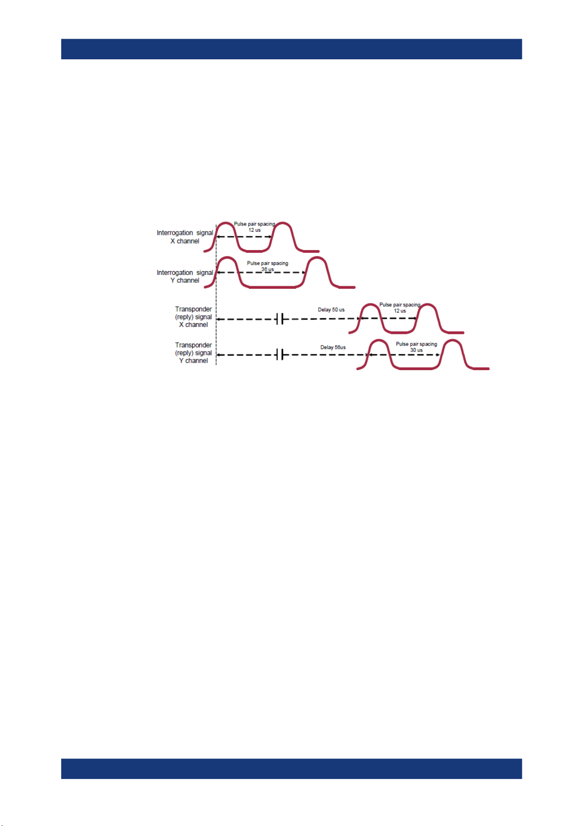
Distance Measurement Equipment (DME)
Figure 2-4: Time characteristic of DME signal envelope for X and Y channel
DME Interrogator
The aircraft's DME interrogator sends a sequence of pulses that are received at the
ground station and, after a defined delay time, are returned at a different frequency.
The frequency offset between sent and received signal is always 63 MHz. The receiver
in the aircraft filters its own pulse sequence out of all received pulses and in this way
determines the time difference between the transmitted and received pulse. The time
difference is used for the calculation of the slant range to the ground station. The distance is typically expressed in nautical miles (NM), where 1 NM corresponds to
1852.02 m and a signal round-trip time of 12.359 µs.
As a result, the precise position of the aircraft can be derived from the flight altitude
and the azimuth angle between the aircraft and ground station (VOR system).
DME Transponder
The DME transponder checks the validity of all received pulses (i.e. the pulse spacing
must be consistent with the channel) in its "decoder". A single pulse, for example, is
filtered out as an invalid interrogation and no reply to this pulse is sent.
For a valid double pulse reception, 2 consecutive pulses are received by the DME
transponder. In this case, the receiver does not react to any further interrogations for
60 µs (= dead time) to ensure that it does not trigger again to its reply signal. The
receiver is not ready to process new interrogation pulses until the reply double pulse
has been fully transmitted. All pulse interrogations that are received at the DME ground
14User Manual 1178.9178.02 ─ 06

R&S®SMBVB-K151/-K152/-K153
station during the dead time are not answered. The time gap between two consecutive
pulses is always at least 60 us.
A reply pulse is sent after a defined delay time after a valid interrogation pulse has
been received.
Echo Rejection
Due to reflection the wanted pulse pair is disturbed by echos. The echo pulse pairs are
typically attenuated by a few dB below and additionally delayed compared to the originally emitted pulse pair. Nevertheless distance measurements must be correct, unless
the echo is too strong.
Velocity Tracking
Due to movement the received pulse pair is doppler-shifted in frequency. Nevertheless
a DME receiver should be able to track this frequency shift.
The velocity is typically expressed in knots (kn). where 1 kn corresponds to 0.5144
m/s.
About the Avionics Options
Distance Measurement Equipment (DME)
Related Settings
For DME settings at the R&S SMBV100B, see Chapter 5, "DME Configuration and Set-
tings", on page 46.
15User Manual 1178.9178.02 ─ 06

R&S®SMBVB-K151/-K152/-K153
3 ILS Configuration and Settings
Option: R&S SMBVB-K151
Access:
► Select "Baseband > ILS".
The remote commands required to define ILS settings are described in Chapter 7.3,
"ILS Commands", on page 84.
Settings
● General Settings..................................................................................................... 16
● ILS Glide Slope Settings......................................................................................... 18
● ILS Localizer Settings............................................................................................. 24
● ILS Marker Beacons Settings..................................................................................32
ILS Configuration and Settings
General Settings
3.1 General Settings
This chapter comprises general settings, which are common for all ILS components.
Access:
► Select "ILS > General".
This dialog comprises general settings of the ILS standard, the default and the
"Save/Recall" settings.
By default, an ILS glide slope modulation signal on an RF carrier with a frequency
of 344.7 MHz or ICAO channel 18X. The dual-tone LF signal with frequencies 90
Hz and 150 Hz and a balanced modulation at SDM of 80 %.
Changing a parameter in the avionic standards causes an instant signal change in the
R&S SMBV100B. There is no extra measurement cycle to calculate the RMS value of
the baseband signal to set the correct RF level.
16User Manual 1178.9178.02 ─ 06

R&S®SMBVB-K151/-K152/-K153
If the avionics standard is activated for the first time, or after every subsequent on/off
sequence, the measurement cycle will take place to determine the correct RF level.
Every subsequent parameter change in the avionic standard is performed without
another measurement cycle to provide a continuous signal output.
Settings
State..............................................................................................................................17
Set To Default................................................................................................................17
Save/Recall................................................................................................................... 17
ILS Component............................................................................................................. 18
State
Activates the avionic standard.
Activation of the standard deactivates a previously active avionic standard. The
"VOR/ILS/DME > Carrier Frequency" setting is applied automatically to the RF "Frequency" and displayed in the status bar.
Remote command:
<subsystem>:STATe on page 84
ILS Configuration and Settings
General Settings
Set To Default
Calls the default settings. The values of the main parameters are listed in the following
table.
Standard Parameter Value
VOR/ILS/DME State Not affected by "Set to default"
VOR Carrier Frequency Mode User Defined
ILS ILS Component Glide Slope (GS)
DME DME Mode Interrogation
Carrier Frequency 108.000000 MHz
ILS GS > Carrier Frequency Mode User Defined
ILS GS > Carrier Frequency 334.700000 MHz
Channel Mode X Channel
Carrier Frequency 1.025 GHz
Remote command:
<subsystem>:PRESet on page 83
Save/Recall
Accesses the "Save/Recall" dialog, that is the standard instrument function for saving
and recalling the complete dialog-related settings in a file. The provided navigation
possibilities in the dialog are self-explanatory.
The settings are saved in a file with predefined extension. You can define the filename
and the directory, in that you want to save the file.
See also, chapter "File and Data Management" in the R&S SMBV100B user manual.
17User Manual 1178.9178.02 ─ 06

R&S®SMBVB-K151/-K152/-K153
Remote command:
<subsystem>:SETTing:CATalog on page 83
<subsystem>:SETTing:DELete on page 83
<subsystem>:SETTing:LOAD on page 83
<subsystem>:SETTing:STORe on page 84
ILS Component
Sets the ILS component.
"Glide slope"
"Localizer"
"Marker Beacons"
Remote command:
[:SOURce<hw>][:BB]:ILS:TYPE on page 85
ILS Configuration and Settings
ILS Glide Slope Settings
Enables the glide slope.
Enables the localizer.
Enables the marker beacons.
3.2 ILS Glide Slope Settings
Access:
1. Select "ILS > General".
2. Select "ILS Component > Glide Slope".
Settings
● General Settings..................................................................................................... 18
● Signal Settings........................................................................................................ 20
● Amplitude Settings.................................................................................................. 22
3.2.1 General Settings
Access:
1. Select "ILS Component > Glide Slope", see Chapter 3.2, "ILS Glide Slope Set-
tings", on page 18.
18User Manual 1178.9178.02 ─ 06

R&S®SMBVB-K151/-K152/-K153
2. Select "ILS > General".
This dialog comprises carrier frequency settings related to the ILS glide slope component of the ILS signal.
Settings
Carrier Frequency Mode............................................................................................... 19
Carrier Frequency......................................................................................................... 19
ICAO Channel............................................................................................................... 19
Sync with Glide Slope/ Sync with Localizer.................................................................. 20
ILS Configuration and Settings
ILS Glide Slope Settings
Carrier Frequency Mode
Sets the mode for the carrier frequency of the signal.
Select "Carrier Frequency Mode > ICAO" to set a standard ILS frequency channel. If
you want to couple carrier frequencies of ILS glide slope and localizer components,
enable Sync with Glide Slope/ Sync with Localizer.
"User Defined"
"ICAO"
Remote command:
[:SOURce<hw>][:BB]:ILS[:GS|GSLope]:FREQuency:MODE on page 88
Carrier Frequency
Requires "Carrier Frequency Mode > User Defined".
Sets the carrier frequency of the signal.
Remote command:
[:SOURce<hw>][:BB]:ILS[:GS|GSLope]:FREQuency on page 88
ICAO Channel
Requires "Carrier Frequency Mode > ICAO".
Sets the ICAO channel and the corresponding transmitting frequency.
If avionic standard modulation is activated and you change the "RF Frequency", the
frequency value of the closest ICAO channel is applied automatically. The "ICAO
Channel" is also updated.
For an overview of the ILS ICAO channel frequencies, see Table A-1.
Activates user-defined variation of the carrier frequency.
Activates variation in predefined steps according to standard ILS
transmitting frequencies (see Table A-1).
19User Manual 1178.9178.02 ─ 06

R&S®SMBVB-K151/-K152/-K153
Remote command:
[:SOURce<hw>][:BB]:ILS[:GS|GSLope]:ICAO:CHANnel on page 89
Sync with Glide Slope/ Sync with Localizer
Activates synchronization of the ILS glide slope with the ILS localizer carrier frequency
or vice versa.
If "Carrier Frequency Mode > User", the ILS glide slope carrier frequency is applied to
the ILS localizer carrier frequency or vice versa.
If "Carrier Frequency Mode > ICAO", the ILS glide slope ICAO channel is applied to the
ILS localizer ICAO channel or vice versa. The ILS glide slope/localizer frequency of the
ICAO channel (Table A-1) is set automatically.
Remote command:
[:SOURce<hw>][:BB]:ILS[:GS|GSLope]:FREQuency:SYNChronize[:STATe]
on page 89
[:SOURce<hw>][:BB]:ILS:LOCalizer:FREQuency:SYNChronize[:STATe]
on page 98
ILS Configuration and Settings
ILS Glide Slope Settings
3.2.2 Signal Settings
Access:
1. Select "ILS Component > Glide Slope", see Chapter 3.2, "ILS Glide Slope Set-
tings", on page 18.
2. Select "ILS > Signal".
This dialog comprises modulation signal settings related to the ILS glide slope
component of the ILS signal.
Settings
Operating Mode............................................................................................................ 20
DDM Polarity................................................................................................................. 21
Up Frequency................................................................................................................21
Down Frequency........................................................................................................... 21
Up/Down Phase............................................................................................................ 21
Operating Mode
Selects the operating mode for the ILS glide slope modulation signal.
20User Manual 1178.9178.02 ─ 06

R&S®SMBVB-K151/-K152/-K153
ILS Configuration and Settings
ILS Glide Slope Settings
"Norm"
"90 Hz"
"150 Hz"
Remote command:
[:SOURce<hw>][:BB]:ILS[:GS|GSLope]:MODE on page 90
DDM Polarity
Defines the polarity for DDM calculation (see "DDM Depth" on page 23).
Remote command:
[:SOURce<hw>][:BB]:ILS[:GS|GSLope]:DDM:POLarity on page 87
ILS glide slope modulation is active.
Amplitude modulation of the output signal with the upper lobe signal
component (90 Hz signal content) of the ILS glide slope signal.
The modulation depth of the 90 Hz signal results from the settings of
the parameters Sum of Depth and DDM Depth according to:
●
"Fly > Down"
AM (90 Hz) = 0.5 × (SDM + DDM × 100 %)
●
"Fly > Up"
AM (90 Hz) = 0.5 × (SDM - DDM × 100 %)
Amplitude modulation of the output signal with the lower lobe signal
component (150 Hz signal content) of the ILS glide slope signal.
The modulation depth of the 150 Hz signal results from the settings of
parameters Sum of Depth and DDM Depth according to:
●
"Fly > Down"
AM (150 Hz) = 0.5 × (SDM + DDM × 100 %)
●
"Fly > Up"
AM (150 Hz) = 0.5 × (SDM - DDM × 100 %)
Up Frequency
Sets the modulation frequency of the upper antenna lobe.
Remote command:
[:SOURce<hw>][:BB]:ILS[:GS|GSLope]:ULOBe[:FREQuency] on page 91
Down Frequency
Sets the modulation frequency of the lower antenna lobe.
Remote command:
[:SOURce<hw>][:BB]:ILS[:GS|GSLope]:LLOBe[:FREQuency] on page 90
Up/Down Phase
Sets the phase between the modulation signals of the upper and lower antenna lobe.
The zero crossing of the lower lobe (150Hz) signal serves as a reference. The angle
refers to the period of the signal of the lower antenna lobe.
Remote command:
[:SOURce<hw>][:BB]:ILS[:GS|GSLope]:PHASe on page 90
21User Manual 1178.9178.02 ─ 06

R&S®SMBVB-K151/-K152/-K153
3.2.3 Amplitude Settings
Access:
1. Select "ILS Component > Glide Slope", see Chapter 3.2, "ILS Glide Slope Set-
tings", on page 18.
2. Select "ILS > Amplitude".
ILS Configuration and Settings
ILS Glide Slope Settings
This dialog comprises amplitude settings related to the ILS glide slope component
of the ILS signal.
Settings
Sum of Depth................................................................................................................ 22
Fly Mode....................................................................................................................... 22
DDM Step......................................................................................................................23
DDM Current................................................................................................................. 23
DDM Depth................................................................................................................... 23
DDM Logarithmic.......................................................................................................... 23
DDM Percent.................................................................................................................23
DDM - SDM Coupling....................................................................................................24
Sum of Depth
Sets the arithmetic sum of the modulation depths of the upper lobe (90 Hz) and lower
lobe (150 Hz) ILS glide slope signal contents.
The RMS modulation depth of the sum signal depends on the phase setting of both
modulation tones.
Remote command:
[:SOURce<hw>][:BB]:ILS[:GS|GSLope]:SDM on page 91
Fly Mode
Selects the simulation mode for the ILS glide slope modulation signal. A change of the
setting automatically changes the sign of the DDM value.
This setting simulates the direction in which the pilot has to correct the course.
"Up"
The 150 Hz modulation signal is predominant, the DDM value is negative (the airplane is too low, it must climb).
22User Manual 1178.9178.02 ─ 06

R&S®SMBVB-K151/-K152/-K153
ILS Configuration and Settings
ILS Glide Slope Settings
"Down"
Remote command:
[:SOURce<hw>][:BB]:ILS[:GS|GSLope]:DDM:DIRection on page 86
DDM Step
Selects the variation of the DDM values.
"Decimal"
"Predifined"
Remote command:
[:SOURce<hw>][:BB]:ILS[:GS|GSLope]:DDM:STEP on page 87
DDM Current
Sets the current of the ILS indicating the instrument corresponding to the DDM value.
The instrument current is calculated according to:
DDM Current µA = DDM Depth [%] × 857,125 µA
A variation of the instrument current automatically leads to a variation of the DDM
value and the DDM value in dB.
Remote command:
[:SOURce<hw>][:BB]:ILS[:GS|GSLope]:DDM:CURRent on page 86
The 90 Hz modulation signal is predominant, the DDM value is positive (the airplane is too high, it must descend).
Decimal variation according to the current cursor position.
Variation in predefined steps according to the standardized DDM values.
DDM Depth
Sets the difference in depth of modulation between the upper lobe (90 Hz) and the
lower lobe (150 Hz) tone of the ILS glide slope modulation signal.
The DDM value is calculated with the formula:
●
"DDM Polarity > 90 Hz - 150 Hz":
DDM = [ AM (90 Hz) - AM (150 Hz) ] / 100%
●
"DDM Polarity > 150 Hz - 90 Hz":
DDM = [ AM (150 Hz) - AM (90 Hz) ] / 100%
A variation of the DDM value automatically leads to a variation of the value of the
instrument current and the DDM value in dB.
Remote command:
[:SOURce<hw>][:BB]:ILS[:GS|GSLope]:DDM[:DEPTh] on page 88
DDM Logarithmic
Sets the DDM value in dB. The dB value is calculated according to:
DDM dB = 20 × LOG [(SDM+DDM×100%) / (SDM-DDM×100%)]
A variation of the value automatically leads to a variation of the DDM value and the
instrument current.
Remote command:
[:SOURce<hw>][:BB]:ILS[:GS|GSLope]:DDM:LOGarithmic on page 86
DDM Percent
Sets the difference in depth of modulation between the upper lobe (90 Hz) and the
lower lobe (150 Hz) tone of the ILS glide slope modulation signal.
23User Manual 1178.9178.02 ─ 06

R&S®SMBVB-K151/-K152/-K153
The DDM value in percent is calculated as follows:
●
"DDM Polarity > 90 Hz - 150 Hz":
DDM = [ AM (90 Hz) - AM (150 Hz) ]
●
"DDM Polarity > 150 Hz - 90 Hz":
DDM = [ AM (150 Hz) - AM (90 Hz) ]
A variation of the DDM value automatically leads to a variation of the value of the
instrument current and the DDM value in dB.
Remote command:
[:SOURce<hw>][:BB]:ILS[:GS|GSLope]:DDM:PCT on page 87
DDM - SDM Coupling
Selects if the DDM value is fixed or is changed with a change of sum of modulation
depths (SDM, see below).
"Fixed DDM"
"Coupled to SDM"
Remote command:
[:SOURce<hw>][:BB]:ILS[:GS|GSLope]:DDM:COUPling on page 85
ILS Configuration and Settings
ILS Localizer Settings
The absolute DDM value stays constant, if the SDM is changed.
The absolute DDM value changes, if the SDM is changed. The DDM
value expressed in dB stays constant.
3.3 ILS Localizer Settings
Access:
1. Select "ILS > General".
2. Select "ILS Component > Localizer".
Settings
● General Settings..................................................................................................... 24
● Signal Settings........................................................................................................ 26
● Amplitude Settings.................................................................................................. 28
● COM/ID Settings..................................................................................................... 30
3.3.1 General Settings
Access:
1. Select "ILS Component > Localizer", see Chapter 3.3, "ILS Localizer Settings",
on page 24.
24User Manual 1178.9178.02 ─ 06

R&S®SMBVB-K151/-K152/-K153
2. Select "ILS > General".
This dialog comprises carrier frequency settings related to the ILS localizer component of the ILS signal.
Settings
Carrier Frequency Mode............................................................................................... 25
Carrier Frequency......................................................................................................... 25
ICAO Channel............................................................................................................... 25
Sync with Glide Slope/ Sync with Localizer.................................................................. 26
ILS Configuration and Settings
ILS Localizer Settings
Carrier Frequency Mode
Sets the mode for the carrier frequency of the signal.
"User Defined"
"ICAO"
Remote command:
[:SOURce<hw>][:BB]:ILS:LOCalizer:FREQuency:MODE on page 98
Carrier Frequency
Requires "Carrier Frequency Mode > User Defined".
Sets the carrier frequency of the signal.
Remote command:
[:SOURce<hw>][:BB]:ILS:LOCalizer:FREQuency on page 98
ICAO Channel
Requires "Carrier Frequency Mode > ICAO".
Sets the ICAO channel and the corresponding transmitting frequency.
If avionic standard modulation is activated and you change the "RF Frequency", the
frequency value of the closest ICAO channel is applied automatically. The "ICAO
Channel" is also updated.
For an overview of the ILS ICAO channel frequencies, see Table A-1.
Activates user-defined variation of the carrier frequency.
Activates variation in predefined steps according to standard ILS
transmitting frequencies (see Table A-1).
Select the ICAO Channel to set a standard ILS frequency channel. If
you want to couple carrier frequencies of ILS glide slope and localizer
components, enable General Settings.
25User Manual 1178.9178.02 ─ 06

R&S®SMBVB-K151/-K152/-K153
Remote command:
[:SOURce<hw>][:BB]:ILS:LOCalizer:ICAO:CHANnel on page 99
Sync with Glide Slope/ Sync with Localizer
Activates synchronization of the ILS glide slope with the ILS localizer carrier frequency
or vice versa.
If "Carrier Frequency Mode > User", the ILS glide slope carrier frequency is applied to
the ILS localizer carrier frequency or vice versa.
If "Carrier Frequency Mode > ICAO", the ILS glide slope ICAO channel is applied to the
ILS localizer ICAO channel or vice versa. The ILS glide slope/localizer frequency of the
ICAO channel (Table A-1) is set automatically.
Remote command:
[:SOURce<hw>][:BB]:ILS[:GS|GSLope]:FREQuency:SYNChronize[:STATe]
on page 89
[:SOURce<hw>][:BB]:ILS:LOCalizer:FREQuency:SYNChronize[:STATe]
on page 98
ILS Configuration and Settings
ILS Localizer Settings
3.3.2 Signal Settings
Access:
1. Select "ILS Component > Localizer", see Chapter 3.3, "ILS Localizer Settings",
on page 24.
2. Select "ILS > Signal".
This dialog comprises audio signal and modulation settings related to the ILS localizer component of the ILS signal.
Settings
Operating Mode............................................................................................................ 26
DDM polarity................................................................................................................. 27
Left Frequency.............................................................................................................. 27
Right Frequency............................................................................................................27
Left/Right Phase............................................................................................................27
Operating Mode
Selects the operating mode for the ILS localizer modulation signal.
26User Manual 1178.9178.02 ─ 06

R&S®SMBVB-K151/-K152/-K153
ILS Configuration and Settings
ILS Localizer Settings
"Norm"
"90 Hz"
"150 Hz"
Remote command:
[:SOURce<hw>][:BB]:ILS:LOCalizer:MODE on page 100
DDM polarity
Defines the polarity for DDM calculation (see "DDM Depth" on page 29).
Remote command:
[:SOURce<hw>][:BB]:ILS:LOCalizer:DDM:POLarity on page 97
ILS localizer modulation is active.
Amplitude modulation of the output signal with the left lobe (90 Hz)
signal component of the ILS localizer signal.
The modulation depth of the 90 Hz signal results from the settings of
parameters Sum of Depth and DDM Depth according to:
●
"Fly > Right"
AM (90 Hz) = 0.5 × (SDM + DDM × 100 %)
●
"Fly > Left"
AM (90 Hz) = 0.5 × (SDM - DDM × 100 %)
Amplitude modulation of the output signal with the right lobe (150 Hz)
signal component of the ILS localizer signal.
The modulation depth of the 150 Hz signal results from the settings of
parameters Sum of Depth and DDM Depth according to:
●
"Fly" = "Right"
AM (150 Hz) = 0.5 × (SDM + DDM × 100 %)
●
"Fly" = "Left"
AM (150 Hz) = 0.5 × (SDM - DDM × 100 %)
Left Frequency
Sets the modulation frequency of the antenna lobe arranged at the left viewed from the
air plane.
Remote command:
[:SOURce<hw>][:BB]:ILS:LOCalizer:LLOBe[:FREQuency] on page 99
Right Frequency
Sets the modulation frequency of the antenna lobe arranged at the right viewed from
the air plane.
Remote command:
[:SOURce<hw>][:BB]:ILS:LOCalizer:RLOBe[:FREQuency] on page 100
Left/Right Phase
Sets the phase between the modulation signals of the left and right antenna lobe. The
zero crossing of the right lobe (150 Hz) signal serves as a reference. The angle refers
to the period of the signal of the right antenna lobe.
Remote command:
[:SOURce<hw>][:BB]:ILS:LOCalizer:PHASe on page 100
27User Manual 1178.9178.02 ─ 06

R&S®SMBVB-K151/-K152/-K153
3.3.3 Amplitude Settings
Access:
1. Select "ILS Component > Localizer", see Chapter 3.3, "ILS Localizer Settings",
on page 24.
2. Select "ILS > Amplitude".
ILS Configuration and Settings
ILS Localizer Settings
This dialog comprises amplitude settings related to the ILS localizer component of
the ILS signal.
Settings
Fly Mode....................................................................................................................... 28
Sum of Depth................................................................................................................ 29
DDM - SDM Coupling....................................................................................................29
DDM Step......................................................................................................................29
DDM Current................................................................................................................. 29
DDM Depth................................................................................................................... 29
DDM Logarithmic.......................................................................................................... 30
DDM Percent.................................................................................................................30
Fly Mode
Selects the simulation mode for the ILS localizer modulation signal. A change of the
setting automatically changes the sign of the DDM value.
This setting simulates the direction in which the pilot has to correct the course.
"Left"
"Right"
Remote command:
[:SOURce<hw>][:BB]:ILS:LOCalizer:DDM:DIRection on page 96
The 150 Hz modulation signal is predominant, the DDM value is negative (the airplane is too far to the right, it must turn to the left).
The 90 Hz modulation signal is predominant, the DDM value is positive (the airplane is too far to the left, it must turn to the right).
28User Manual 1178.9178.02 ─ 06

R&S®SMBVB-K151/-K152/-K153
Sum of Depth
Sets the arithmetic sum of the modulation depths of the left lobe (90 Hz) and right lobe
(150 Hz) ILS localizer signal contents.
The RMS modulation depth of the sum signal depends on the phase setting of both
modulation tones.
The "Sum of Depth" and "COM/ID > Depth" must be smaller than 100 %.
Remote command:
[:SOURce<hw>][:BB]:ILS:LOCalizer:SDM on page 101
DDM - SDM Coupling
Selects if the DDM value is fixed or is changed with a change of sum of modulation
depths (SDM, see below).
"Fixed DDM"
"Coupled to
SDM"
Remote command:
[:SOURce<hw>][:BB]:ILS:LOCalizer:DDM:COUPling on page 95
ILS Configuration and Settings
ILS Localizer Settings
The absolute DDM value stays constant, if the SDM is changed.
The absolute DDM value changes, if the SDM is changed. The DDM
value expressed in dB stays constant.
DDM Step
Selects the variation step of the DDM values.
"Decimal"
"Predifined"
Remote command:
[:SOURce<hw>][:BB]:ILS:LOCalizer:DDM:STEP on page 98
DDM Current
Sets the current of the ILS indicating instrument corresponding to the DDM value. The
instrument current is calculated according to:
DDM µA = DDM × 967.75 µA
A variation of the instrument current automatically leads to a variation of the DDM
value and the DDM value in dB.
Remote command:
[:SOURce<hw>][:BB]:ILS:LOCalizer:DDM:CURRent on page 95
DDM Depth
Sets the difference in depth of modulation (DDM) between the signal of the left lobe
(90 Hz) and the right lobe (150 Hz) of the ILS localizer modulation signal.
The DDM value in percent is calculated as follows:
●
"DDM Polarity > 90 Hz - 150 Hz" (default setting):
DDM = [ AM (90 Hz) - AM (150 Hz) ] / 100 %
●
"DDM Polarity > 150 Hz - 90 Hz":
DDM = [ AM (150 Hz) - AM (90 Hz) ] / 100 %
A variation of the DDM value automatically leads to a variation of the DDM value in dB
and the value of the instrument current.
Decimal variation according to the current cursor position.
Variation in predefined steps according to the standardized DDM values.
29User Manual 1178.9178.02 ─ 06

R&S®SMBVB-K151/-K152/-K153
Remote command:
[:SOURce<hw>][:BB]:ILS:LOCalizer:DDM[:DEPTh] on page 97
DDM Logarithmic
Sets the DDM value in dB. The dB value is calculated according to:
DDM dB = 20 × LOG [(SDM + DDM × 100 %) / (SDM - DDM × 100 %)]
A variation of the value automatically leads to a variation of the DDM value and the
instrument current.
Remote command:
[:SOURce<hw>][:BB]:ILS:LOCalizer:DDM:LOGarithmic on page 96
DDM Percent
Sets the difference in depth of modulation between the signal of the left lobe (90 Hz)
and the right lobe (150 Hz).
The DDM value in percent is calculated by the following formulas:
●
"DDM Polarity > 90 Hz - 150 Hz" (default setting):
DDM = [ AM(90 Hz) - AM (150 Hz) ]
●
"DDM Polarity > 150 Hz - 90 Hz":
DDM = [ AM(150 Hz) - AM (90 Hz) ]
A variation of the DDM value automatically leads to a variation of the DDM value in dB
and the value of the instrument current.
Remote command:
[:SOURce<hw>][:BB]:ILS:LOCalizer:DDM:PCT on page 96
ILS Configuration and Settings
ILS Localizer Settings
3.3.4 COM/ID Settings
Access:
1. Select "ILS Component > Localizer", see Chapter 3.3, "ILS Localizer Settings",
on page 24.
2. Select "ILS > COM/ID".
30User Manual 1178.9178.02 ─ 06
 Loading...