


EUTRA/LTE/IoT
R&S®SMBVB-K55/-K84/-K85/-K112/-
K113/-K115/-K119/-K143/-K146/-K175
User Manual
(;Üßì2)
1178819402
Version 09

This document describes the following software options:
●
R&S®SMBVB-K55, LTE Rel. 8 (1423.7830.xx)
●
R&S®SMBVB-K84, LTE Rel. 9 (1423.7901.xx)
●
R&S®SMBVB-K85, LTE Rel. 10 (1423.7918.xx)
●
R&S®SMBVB-K112, LTE Rel. 11 (1423.8037.xx)
●
R&S®SMBVB-K113, LTE Rel. 12 (1423.8043.xx)
●
R&S®SMBVB-K115, Cellular IoT Rel. 13 (1424.8108.xx)
●
R&S®SMBVB-K119, LTE Rel. 13/ Rel. 14/ Rel. 15 (1423.8066.xx)
●
R&S®SMBVB-K143, Cellular IoT Rel. 14 (1423.8637.xx)
●
R&S®SMBVB-K146, Cellular IoT Rel. 15 (1423.8808.xx)
●
R&S®SMBVB-K175, U-plane generation (1423.8989.xx)
This manual describes firmware version FW 5.00.044.xx and later of the R&S®SMBV100B.
© 2021 Rohde & Schwarz GmbH & Co. KG
Mühldorfstr. 15, 81671 München, Germany
Phone: +49 89 41 29 - 0
Email: info@rohde-schwarz.com
Internet: www.rohde-schwarz.com
Subject to change – data without tolerance limits is not binding.
R&S® is a registered trademark of Rohde & Schwarz GmbH & Co. KG.
Trade names are trademarks of the owners.
1178.8194.02 | Version 09 | EUTRA/LTE/IoT
The following abbreviations are used throughout this manual: R&S®SMBV100B is abbreviated as R&S SMBVB, R&S®WinIQSIM2
is abbreviated as R&S WinIQSIM2
TM

ContentsEUTRA/LTE/IoT
Contents
1 Welcome to the EUTRA/LTE/IoT options........................................... 13
1.1 Key features.................................................................................................................13
1.2 Accessing the EUTRA/LTE dialog............................................................................. 15
1.3 What's new...................................................................................................................15
1.4 Documentation overview............................................................................................15
1.4.1 Getting started manual..................................................................................................16
1.4.2 User manuals and help................................................................................................. 16
1.4.3 Service manual............................................................................................................. 16
1.4.4 Instrument security procedures.....................................................................................16
1.4.5 Printed safety instructions............................................................................................. 16
1.4.6 Data sheets and brochures........................................................................................... 17
1.4.7 Release notes and open source acknowledgment (OSA)............................................ 17
1.4.8 Application notes, application cards, white papers, etc.................................................17
1.5 Scope........................................................................................................................... 17
1.6 Notes on screenshots.................................................................................................18
2 About the EUTRA/LTE options........................................................... 19
2.1 Required options.........................................................................................................19
2.2 Introduction to the EUTRA/LTE technology............................................................. 19
2.2.1 LTE downlink transmission scheme.............................................................................. 20
2.2.1.1 OFDMA parameterization............................................................................................. 21
Channel bandwidth....................................................................................................... 21
Frame structure type 1 (FDD)....................................................................................... 21
Frame structure type 2 (TDD)....................................................................................... 22
2.2.1.2 Downlink resource grid..................................................................................................23
2.2.1.3 Downlink data transmission.......................................................................................... 24
2.2.1.4 Downlink control information transmission....................................................................24
2.2.1.5 Downlink reference signal structure and cell search.....................................................26
Mapping of reference signals to antenna ports............................................................. 26
Cell-specific downlink reference signals....................................................................... 27
MBSFN reference signals............................................................................................. 29
UE-specific reference signal (DMRS)........................................................................... 30
3User Manual 1178.8194.02 ─ 09

ContentsEUTRA/LTE/IoT
Positioning reference signals........................................................................................ 31
CSI reference signals....................................................................................................32
2.2.1.6 Downlink physical layer procedures..............................................................................33
2.2.2 LTE uplink transmission scheme...................................................................................33
2.2.2.1 SC-FDMA parameterization.......................................................................................... 35
2.2.2.2 Uplink data transmission............................................................................................... 35
2.2.2.3 Uplink control information transmission........................................................................ 36
2.2.2.4 Uplink reference signal structure...................................................................................38
2.2.2.5 Uplink physical layer procedures.................................................................................. 39
2.2.3 LTE MIMO concepts......................................................................................................41
2.2.3.1 Downlink MIMO.............................................................................................................41
Spatial multiplexing....................................................................................................... 41
Transmit diversity.......................................................................................................... 44
Beamforming.................................................................................................................44
2.2.3.2 Uplink MIMO................................................................................................................. 44
2.2.4 LTE MBMS concepts.....................................................................................................45
2.2.5 LTE Release 10 (LTE-Advanced) introduction.............................................................. 45
2.2.5.1 Carrier aggregation....................................................................................................... 45
2.2.5.2 Enhanced uplink SC-FDMA.......................................................................................... 47
2.2.5.3 Enhanced MIMO schemes............................................................................................48
2.2.6 LTE Release 11 introduction......................................................................................... 50
2.2.7 LTE Release 12 introduction......................................................................................... 53
2.2.8 LTE Release 13/14 introduction.................................................................................... 54
2.2.8.1 Frame structure type 3 (LAA) and partial subframes.................................................... 55
2.2.8.2 DCI format 1C............................................................................................................... 56
2.2.8.3 Physical channels and signals in an LAA SCell............................................................ 57
2.2.8.4 Full dimension MIMO (FD-MIMO)................................................................................. 58
2.2.8.5 PUCCH formats 4 and 5............................................................................................... 59
2.2.8.6 TDD special subframe configuration 10........................................................................ 59
2.2.8.7 DMRS enhancements and DCI format 2C/2D.............................................................. 59
3 Find out the implemented 3GPP specification..................................61
4 EUTRA/LTE configuration and settings............................................. 62
4.1 General settings.......................................................................................................... 62
4User Manual 1178.8194.02 ─ 09

ContentsEUTRA/LTE/IoT
4.2 General DL settings / general TDD DL settings....................................................... 68
4.2.1 PDSCH scheduling settings.......................................................................................... 69
4.2.2 DL carrier aggregation configuration.............................................................................71
4.2.2.1 About DL carrier aggregation........................................................................................ 71
4.2.2.2 How to enable carrier aggregation and cross-carrier scheduling..................................72
4.2.2.3 Carrier aggregation settings..........................................................................................74
4.2.3 MBSFN settings............................................................................................................ 78
4.2.4 Physical settings........................................................................................................... 92
4.2.5 Cell-specific settings..................................................................................................... 96
4.2.6 TDD frame structure settings...................................................................................... 100
4.2.7 Downlink signals settings............................................................................................ 101
4.2.7.1 Synchronization and cell-specific reference signals (CRS/SYNC) settings................ 101
4.2.7.2 NB-IoT synchronization and cell-specific reference signals (NRS/N-SYNC) settings.102
4.2.7.3 Positioning reference signal (PRS) settings................................................................104
4.2.7.4 CSI-RS settings...........................................................................................................108
4.2.7.5 Discovery reference signals (DRS) settings................................................................114
4.2.7.6 Narrowband positioning reference signals (NPRS) settings....................................... 120
4.2.7.7 NB-IoT wake-up signal (NWUS) settings.................................................................... 122
4.2.8 Antenna ports settings................................................................................................ 124
4.3 DL frame configuration settings..............................................................................126
4.3.1 General frame configuration settings.......................................................................... 126
4.3.2 Dummy data configuration settings.............................................................................128
4.3.3 User configuration settings..........................................................................................129
4.3.4 Auto sequence configuration.......................................................................................137
4.3.4.1 How to enable and use the auto sequence mode.......................................................138
4.3.4.2 Auto sequence settings...............................................................................................141
4.3.5 EPDCCH configuration settings.................................................................................. 146
4.3.6 Scrambling configuration settings............................................................................... 151
4.3.7 SPS configuration settings.......................................................................................... 152
4.3.8 LAA settings................................................................................................................ 157
4.3.9 Subframe configuration settings..................................................................................162
4.3.10 DL resource allocation table........................................................................................163
4.3.11 PCFICH settings......................................................................................................... 170
5User Manual 1178.8194.02 ─ 09

ContentsEUTRA/LTE/IoT
4.3.12 PHICH settings............................................................................................................172
4.3.13 (E)PDCCH settings..................................................................................................... 175
4.3.14 (E)PDCCH format variable..........................................................................................179
4.3.15 DCI format configuration............................................................................................. 188
4.4 Enhanced PBCH, PDSCH and PMCH settings....................................................... 201
4.4.1 Precoding settings.......................................................................................................202
4.4.2 CSI-RS settings...........................................................................................................207
4.4.3 Scrambling settings.....................................................................................................208
4.4.4 Channel coding settings..............................................................................................209
4.5 DL antenna port mapping settings.......................................................................... 211
4.6 General UL settings.................................................................................................. 217
4.6.1 UL carrier aggregation configuration...........................................................................218
4.6.1.1 About UL carrier aggregation...................................................................................... 219
4.6.1.2 How to enable UL carrier aggregation........................................................................ 219
4.6.1.3 Carrier aggregation settings........................................................................................222
4.6.2 Physical settings......................................................................................................... 224
4.6.3 Cell-specific settings................................................................................................... 228
4.6.4 TDD frame structure settings...................................................................................... 231
4.6.5 Signals settings........................................................................................................... 232
4.6.5.1 UL reference signals................................................................................................... 232
4.6.5.2 Cell-specific SRS settings........................................................................................... 234
4.6.6 PRACH settings.......................................................................................................... 236
4.6.7 PUSCH structure.........................................................................................................238
4.6.8 PUCCH structure........................................................................................................ 239
4.7 UL frame configuration settings..............................................................................242
4.7.1 General scheduling configuration settings.................................................................. 242
4.7.2 Subframe configuration............................................................................................... 245
4.7.3 UL allocation table.......................................................................................................247
4.8 User equipment configuration................................................................................. 252
4.8.1 Common settings........................................................................................................ 253
4.8.2 Physical uplink control channel (PUCCH)...................................................................255
4.8.3 FRC configuration....................................................................................................... 256
4.8.4 Physical uplink shared channel (PUSCH)...................................................................260
6User Manual 1178.8194.02 ─ 09

ContentsEUTRA/LTE/IoT
4.8.5 Demodulation reference signal (DMRS)..................................................................... 265
4.8.6 Sounding reference signal (SRS)................................................................................267
4.8.7 Sidelink settings.......................................................................................................... 277
4.8.7.1 Common sidelink settings........................................................................................... 277
4.8.7.2 Resource pool control and resource pool settings...................................................... 279
4.8.7.3 Resource pool data settings........................................................................................285
4.8.7.4 RMC settings...............................................................................................................289
4.8.7.5 Synchronization settings............................................................................................. 290
4.8.7.6 SCI configuration settings........................................................................................... 292
4.8.7.7 SCI format configuration............................................................................................. 295
4.8.7.8 Allocation settings....................................................................................................... 298
4.8.7.9 PSCCH, PSDCH and PSSCH enhanced settings...................................................... 301
4.8.8 Antenna port mapping.................................................................................................303
4.8.9 PRACH power ramping...............................................................................................306
4.8.10 PRACH configuration.................................................................................................. 307
4.9 Enhanced PUSCH settings.......................................................................................310
4.9.1 Common PUSCH settings...........................................................................................310
4.9.2 Demodulation reference signal (DMRS)..................................................................... 313
4.9.3 Channel coding / multiplexing..................................................................................... 314
4.10 Enhanced PUCCH settings...................................................................................... 320
4.10.1 Common settings........................................................................................................ 320
4.10.2 Channel coding / multiplexing..................................................................................... 322
4.10.3 Demodulation reference signal (DMRS)..................................................................... 326
5 Generating eMTC/NB-IoT signals..................................................... 328
5.1 About eMTC............................................................................................................... 329
5.1.1 Physical layer.............................................................................................................. 331
5.1.2 PBCH.......................................................................................................................... 332
5.1.3 PDSCH........................................................................................................................332
5.1.4 MPDCCH.................................................................................................................... 336
5.1.5 PUSCH........................................................................................................................340
5.1.6 PUCCH....................................................................................................................... 343
5.1.7 PRACH........................................................................................................................345
5.2 About NB-IoT............................................................................................................. 346
7User Manual 1178.8194.02 ─ 09

ContentsEUTRA/LTE/IoT
5.2.1 Physical layer.............................................................................................................. 347
5.2.2 NPSS and NSSS.........................................................................................................350
5.2.3 NRS.............................................................................................................................351
5.2.4 NPBCH........................................................................................................................352
5.2.5 NPDCCH.....................................................................................................................353
5.2.6 NPDSCH..................................................................................................................... 357
5.2.7 NDRS.......................................................................................................................... 359
5.2.8 NPUSCH..................................................................................................................... 360
5.2.9 NPRACH..................................................................................................................... 363
5.3 eMTC/NB-IoT-specific configuration and settings.................................................366
5.3.1 NB-IoT carrier allocation............................................................................................. 367
5.3.2 NPBCH, NPDCCH and NPDSCH settings..................................................................374
5.3.2.1 Search space settings.................................................................................................377
5.3.2.2 NB-IoT DCI configuration............................................................................................ 379
5.3.2.3 NB-IoT allocations (NPBCH, NPDCCH, NPDSCH).................................................... 393
5.3.2.4 NPBCH channel coding and MIB-NB configuration.................................................... 397
5.3.2.5 NPDSCH and NPDCCH channel coding and scrambling........................................... 401
5.3.3 FRC settings............................................................................................................... 404
5.3.4 NDMRS settings..........................................................................................................407
5.3.5 NPUSCH settings........................................................................................................409
5.3.5.1 NB-IoT allocation settings........................................................................................... 412
5.3.5.2 NPUSCH enhanced settings.......................................................................................417
5.3.6 NPRACH settings........................................................................................................421
5.3.7 eMTC DL allocations settings..................................................................................... 427
5.3.7.1 eMTC DL valid subframes and frequency hopping..................................................... 427
5.3.7.2 Search space settings.................................................................................................430
5.3.7.3 eMTC DCI configuration..............................................................................................432
5.3.7.4 eMTC allocations (PBCH, MPDCCH, PDSCH)...........................................................444
5.3.7.5 PBCH channel coding and SIB-BR configuration....................................................... 448
5.3.7.6 PDSCH channel coding and scrambling..................................................................... 451
5.3.7.7 MPDCCH configuration...............................................................................................456
5.3.8 eMTC PUSCH settings............................................................................................... 457
5.3.8.1 Cell-specific eMTC PUSCH settings........................................................................... 459
8User Manual 1178.8194.02 ─ 09

ContentsEUTRA/LTE/IoT
5.3.8.2 UE-specific eMTC PUSCH transmissions settings..................................................... 459
5.3.8.3 eMTC PUSCH channel coding and multiplexing settings........................................... 465
5.3.9 eMTC PUCCH settings............................................................................................... 469
5.3.9.1 Cell-specific eMTC PUCCH settings...........................................................................471
5.3.9.2 UE-specific eMTC PUCCH settings............................................................................ 473
5.3.9.3 eMTC PUCCH channel coding and multiplexing settings........................................... 473
5.3.10 eMTC PRACH settings............................................................................................... 476
6 Observing current allocations on the time plan..............................482
6.1 OFDMA time plan...................................................................................................... 482
6.2 SC-FDMA time plan...................................................................................................484
6.3 TDD time plan............................................................................................................ 485
6.4 eMTC/NB-IoT indication in the DL time plan...........................................................486
6.5 eMTC/NB-IoT indication in the UL time plan...........................................................489
6.6 TDD time plan............................................................................................................ 490
7 Performing BS tests according to TS 36.141.................................. 493
7.1 Introduction to conformance testing...................................................................... 493
7.1.1 UE conformance testing..............................................................................................493
7.1.2 BS conformance testing.............................................................................................. 495
7.1.3 Repeater conformance testing.................................................................................... 495
7.2 Required options.......................................................................................................495
7.3 Supported test cases................................................................................................495
7.3.1 Generic structure of the description of the implemented test cases........................... 496
7.4 Standard test setups.................................................................................................497
7.4.1 Standard test setup - one path....................................................................................497
7.5 General considerations............................................................................................ 497
7.6 User interface............................................................................................................ 501
7.6.1 Test case settings........................................................................................................501
7.6.2 Instrument settings......................................................................................................503
7.6.3 Frequency allocation settings......................................................................................504
7.6.4 Wanted signal and cell-specific settings......................................................................505
7.6.5 Diagram.......................................................................................................................507
7.6.6 Apply settings..............................................................................................................507
7.7 Transmitter characteristics (TS 36.141, chapter 6)................................................ 507
9User Manual 1178.8194.02 ─ 09

ContentsEUTRA/LTE/IoT
7.7.1 Prior considerations.................................................................................................... 508
7.7.2 Introduction to the unwanted emissions tests............................................................. 508
7.7.3 General workflow for carrying out a transmitter test....................................................510
7.7.4 Interfering signal settings............................................................................................ 512
7.7.5 Test case 6.7: transmitter intermodulation.................................................................. 514
7.8 Receiver characteristics (TS 36.141, chapter 7).....................................................515
7.8.1 Prior considerations.................................................................................................... 516
7.8.2 General workflow for carrying out a receiver test........................................................517
7.8.3 Interfering signal settings............................................................................................ 518
7.8.4 Test case 7.2: reference sensitivity level.....................................................................521
7.8.5 Test case 7.3: dynamic range..................................................................................... 522
7.8.6 Test case 7.4: in-channel selectivity (ICS).................................................................. 524
8 Generating user plane data...............................................................527
8.1 Required options.......................................................................................................527
8.2 File format and folder structure...............................................................................527
9 Signal control and signal characteristics........................................529
9.1 Time domain windowing settings............................................................................529
9.2 Filter/clipping/ARB settings..................................................................................... 530
9.2.1 Filter settings...............................................................................................................530
9.2.2 Clipping settings..........................................................................................................536
9.2.3 ARB settings............................................................................................................... 537
9.3 Adjusting the signal power...................................................................................... 538
9.3.1 General power-related settings overview....................................................................538
9.3.2 Downlink power-related settings overview.................................................................. 538
9.3.3 Uplink power-related settings overview.......................................................................539
9.3.4 Power settings.............................................................................................................540
9.4 Trigger settings......................................................................................................... 543
9.5 Marker settings..........................................................................................................548
9.6 Clock settings............................................................................................................551
9.7 Global connectors settings......................................................................................552
10 Remote-control commands...............................................................553
10.1 Primary commands...................................................................................................555
10User Manual 1178.8194.02 ─ 09

ContentsEUTRA/LTE/IoT
10.2 Filter/clipping/power................................................................................................. 559
10.2.1 Filter settings...............................................................................................................559
10.2.2 Clipping settings..........................................................................................................563
10.2.3 Time domain windowing settings................................................................................ 564
10.2.4 Power settings.............................................................................................................565
10.3 Clock.......................................................................................................................... 567
10.4 Timing configuration.................................................................................................568
10.5 Trigger........................................................................................................................568
10.6 Marker........................................................................................................................ 573
10.7 General TDD commands.......................................................................................... 576
10.8 General downlink commands.................................................................................. 577
10.9 General uplink commands....................................................................................... 590
10.10 DL frame configuration.............................................................................................602
10.11 DL MBFSN..................................................................................................................611
10.12 DL carrier aggregation..............................................................................................623
10.13 CSI-RS........................................................................................................................ 628
10.14 LAA and DRS.............................................................................................................635
10.15 Enhanced PBCH, PDSCH, PMCH.............................................................................645
10.16 Enhanced PCFICH, PHICH and PDCCH configuration.......................................... 654
10.17 Auto sequence.......................................................................................................... 689
10.18 UL frame configuration.............................................................................................701
10.19 UL carrier aggregation..............................................................................................706
10.20 UL enhanced..............................................................................................................710
10.21 User configuration.................................................................................................... 726
10.22 EPDCCH..................................................................................................................... 738
10.23 Dummy data configuration.......................................................................................742
10.24 SPS configuration..................................................................................................... 744
10.25 User equipment......................................................................................................... 745
10.26 Sidelink configuration.............................................................................................. 770
10.27 eMTC/NB-IoT commands..........................................................................................799
10.27.1 General IoT downlink.................................................................................................. 823
10.27.1.1 Physical settings......................................................................................................... 823
10.27.1.2 DL reference and sychronization signals.................................................................... 824
11User Manual 1178.8194.02 ─ 09

ContentsEUTRA/LTE/IoT
10.27.1.3 NPRS.......................................................................................................................... 825
10.27.1.4 NB-IoT wake-up signal................................................................................................829
10.27.1.5 NB-IoT carrier allocation............................................................................................. 831
10.27.1.6 eMTC bitmap, valid subframes, hopping and common search space........................ 838
10.27.2 DL IoT frame configuration..........................................................................................843
10.27.2.1 NB-IoT DCI configuration............................................................................................ 843
10.27.2.2 NB-IoT allocation.........................................................................................................854
10.27.2.3 NPBCH, NPDCCH, NPDSCH enhanced settings.......................................................858
10.27.2.4 NB-IoT user configuration........................................................................................... 863
10.27.2.5 eMTC DCI configuration..............................................................................................864
10.27.2.6 eMTC allocations........................................................................................................ 878
10.27.2.7 PBCH and PDSCH enhanced settings....................................................................... 883
10.27.2.8 MPDCCH configuration...............................................................................................892
10.27.3 General IoT uplink.......................................................................................................894
10.27.4 IoT UE configuration................................................................................................... 902
10.28 Test case wizard remote-control commands..........................................................933
Annex.................................................................................................. 944
A Conflict handling................................................................................944
A.1 Downlink.................................................................................................................... 944
A.2 Uplink......................................................................................................................... 945
A.3 DCI conflict handling................................................................................................ 946
B Subframes handling...........................................................................949
B.1 Copy/paste subframe................................................................................................949
B.2 Number of configurable subframes........................................................................ 949
B.3 Four configurable frames in uplink and downlink direction.................................950
B.3.1 Uplink direction............................................................................................................950
B.3.2 Downlink direction....................................................................................................... 952
Glossary: 3GPP specifications, references.....................................954
List of commands.............................................................................. 956
Index....................................................................................................980
12User Manual 1178.8194.02 ─ 09

Welcome to the EUTRA/LTE/IoT optionsEUTRA/LTE/IoT
Key features
1 Welcome to the EUTRA/LTE/IoT options
The R&S SMBV100B-K55/-K84/-K85/-K112/-K113/-K115/-K119/-K143/-K145/-K175 are
firmware applications that add functionality to generate signals in accordance with the
3GPP standard EUTRA/LTE.
In the following, the terms LTE and EUTRA are used interchangeably.
1.1 Key features
Preamble
All supported LTE features are in line with 3GPP Release 14; the following official
3GPP specifications are implemented:
●
3GPP TS 36.211, version 15.6.0
●
3GPP TS 36.212, version 15.6.1
●
3GPP TS 36.213, version 15.6.0
The R&S SMBV100B-K55/-K84/-K85/-K112/-K113/-K119 key features
The R&S SMBV100B simulates EUTRA/LTE at the physical channel level. The following list gives an overview of the functions provided for generating an EUTRA/LTE signal:
●
Supports FDD and TDD
●
Intuitive user interface with graphical display of time plan
●
Full support of P-SYNC, S-SYNC and DL reference signal derived from cell ID
●
PBCH, PDSCH, (E)PDCCH, PCFICH, PHICH supported
●
Downlink 256QAM for PDSCH and PMCH
●
PDCCH with full DCI configuration (all DCI formats supported), incl. DCI format 1C
for eIMTA-RNTI
●
Channel coding and scrambling for PDSCH and PBCH (including MIB)
●
Automatic PDSCH scheduling from DCI
●
Automatic scheduling of downlink transmissions according to long HARQ patterns
●
Full downlink MIMO and transmit diversity support
●
Uplink MIMO support
●
Supports PUSCH with channel coding and scrambling
●
Configuration of all PRACH and PUCCH formats
●
Fixed reference channels (FRC) in line with 3GPP TS 36.141
●
Downlink test models (E-TMs) in line with 3GPP TS 36.141, incl. E-TMs for
256QAM
●
Test case wizard
13User Manual 1178.8194.02 ─ 09

Welcome to the EUTRA/LTE/IoT optionsEUTRA/LTE/IoT
Key features
●
Simulation of single-layer, dual-layer and up to eight-layer beamforming scenarios
(transmission modes 7, 8 and 9) on antenna ports 5 and 7 to 14
●
Support of MBMS single frequency network (MBSFN) subframes on antenna port 4
●
Generation of positioning reference signals (PRS) on antenna port 6
●
Generation of LTE-Advanced downlink and uplink carrier aggregation scenarios (up
to 5 carriers) with support for cross-carrier scheduling; incl. uplink carrier aggregation with mixed duplexing
●
LTE-Advanced enhanced SC-FDMA with PUSCH/PUCCH synchronous transmission and clustered PUSCH
●
Support of CSI reference signals
●
Support of DL LAA bursts configuration
●
Support of QAM256 in uplink
The R&S SMBV100B-K115 key features
The R&S SMBV100B simulates eMTC and NB-IoT at the physical channel level. The
following is an overview of provided functions:
●
Supports uplink eMTC and NB-IoT configuration, and downlink NB-IoT configuration for CAT-M1 and CAT-NB1 devices
●
Supports IoT standalone configuration and mixed configuration with LTE
●
Supports NB-IoT in-band and guard band operating modes
●
Intuitive user interface with graphical display of time plan
●
Support of coverage enhancement CE modes A and B and CE levels 0, 1 and 2
●
Support of the new NB channels and synchronization signals (NPSS, NSSS and
DL reference signal derived from NCell ID)
●
MPBCH, PDSCH, PBCH supported
●
DCI-based configuration of NPDCCH and NPDSCH
●
Channel coding and scrambling for NPDCCH, NPDSCH and NPBCH (including
SIB type 1)
●
Supports NPUSCH with channel coding and scrambling
●
NPRACH configuration
●
Support of all specified modulation schemes
The R&S SMBV100B-K143 key features
●
3GPP LTE Rel. 14 (eMTC and NB-IoT)
Introduces eMTC widebands and new types CAT-M2 and CAT-NB2 devices.
The R&S SMBV100B-K146 key features
●
3GPP LTE Rel. 15 (NB-IoT)
Introduces NB-IoT TDD mode in UL, FDD NPRACH formats, early data transmission, NB-IoT wake up signal and scheduling request in uplink for NPUSCH F2.
This user manual contains a description of the functionality that the application provides, including remote control operation.
14User Manual 1178.8194.02 ─ 09

Welcome to the EUTRA/LTE/IoT optionsEUTRA/LTE/IoT
All functions not discussed in this manual are the same as in the base unit and are
described in the R&S SMBV100B user manual. The latest version is available at:
www.rohde-schwarz.com/manual/SMBV100B
Installation
You can find detailed installation instructions in the delivery of the option or in the
R&S SMBV100B service manual.
1.2 Accessing the EUTRA/LTE dialog
To open the dialog with EUTRA/LTE settings
► In the block diagram of the R&S SMBV100B, select "Baseband > EUTRA/LTE".
A dialog box opens that display the provided general settings.
Documentation overview
The signal generation is not started immediately. To start signal generation with the
default settings, select "State > On".
1.3 What's new
This documentation describes version 5.00.044 and higher of the EUTRA/LTE/IoT firmware application. Compared to version 4.90.049, it provides the following new features
and changes:
●
Support of test models for O-RAN, see "Test Models" on page 66
●
Flexible configuration of starting seed for data sources for PDSCH, see "Data
Source Init" on page 135
●
Flexible configuration of starting seed for data sources for PUSCH, see "Initializa-
tion (tab General)" on page 262
1.4 Documentation overview
This section provides an overview of the R&S SMBV100B user documentation. Unless
specified otherwise, you find the documents on the R&S SMBV100B product page at:
www.rohde-schwarz.com/manual/smbv100b
15User Manual 1178.8194.02 ─ 09

1.4.1 Getting started manual
Introduces the R&S SMBV100B and describes how to set up and start working with the
product. Includes basic operations, typical measurement examples, and general information, e.g. safety instructions, etc. A printed version is delivered with the instrument.
1.4.2 User manuals and help
Separate manuals for the base unit and the software options are provided for download:
●
Base unit manual
Contains the description of all instrument modes and functions. It also provides an
introduction to remote control, a complete description of the remote control commands with programming examples, and information on maintenance, instrument
interfaces and error messages. Includes the contents of the getting started manual.
●
Software option manual
Contains the description of the specific functions of an option. Basic information on
operating the R&S SMBV100B is not included.
Welcome to the EUTRA/LTE/IoT optionsEUTRA/LTE/IoT
Documentation overview
The contents of the user manuals are available as help in the R&S SMBV100B. The
help offers quick, context-sensitive access to the complete information for the base unit
and the software options.
All user manuals are also available for download or for immediate display on the Internet.
1.4.3 Service manual
Describes the performance test for checking compliance with rated specifications, firmware update, troubleshooting, adjustments, installing options and maintenance.
The service manual is available for registered users on the global Rohde & Schwarz
information system (GLORIS):
https://gloris.rohde-schwarz.com
1.4.4 Instrument security procedures
Deals with security issues when working with the R&S SMBV100B in secure areas. It
is available for download on the Internet.
1.4.5 Printed safety instructions
Provides safety information in many languages. The printed document is delivered with
the product.
16User Manual 1178.8194.02 ─ 09

Welcome to the EUTRA/LTE/IoT optionsEUTRA/LTE/IoT
1.4.6 Data sheets and brochures
The data sheet contains the technical specifications of the R&S SMBV100B. It also
lists the options and their order numbers and optional accessories.
The brochure provides an overview of the instrument and deals with the specific characteristics.
See www.rohde-schwarz.com/brochure-datasheet/smbv100b
1.4.7 Release notes and open source acknowledgment (OSA)
The release notes list new features, improvements and known issues of the current
firmware version, and describe the firmware installation.
The open-source acknowledgment document provides verbatim license texts of the
used open source software.
See www.rohde-schwarz.com/firmware/smbv100b
Scope
1.4.8 Application notes, application cards, white papers, etc.
These documents deal with special applications or background information on particular topics.
See www.rohde-schwarz.com/application/smbv100b
1.5 Scope
Tasks (in manual or remote operation) that are also performed in the base unit in the
same way are not described here.
In particular, it includes:
●
Managing settings and data lists, like saving and loading settings, creating and
accessing data lists, or accessing files in a particular directory.
●
Information on regular trigger, marker and clock signals and filter settings, if appropriate.
●
General instrument configuration, such as checking the system configuration, configuring networks and remote operation
●
Using the common status registers
For a description of such tasks, see the R&S SMBV100B user manual.
17User Manual 1178.8194.02 ─ 09

1.6 Notes on screenshots
When describing the functions of the product, we use sample screenshots. These
screenshots are meant to illustrate as many as possible of the provided functions and
possible interdependencies between parameters. The shown values may not represent
realistic usage scenarios.
The screenshots usually show a fully equipped product, that is: with all options installed. Thus, some functions shown in the screenshots may not be available in your particular product configuration.
Welcome to the EUTRA/LTE/IoT optionsEUTRA/LTE/IoT
Notes on screenshots
18User Manual 1178.8194.02 ─ 09

About the EUTRA/LTE optionsEUTRA/LTE/IoT
Introduction to the EUTRA/LTE technology
2 About the EUTRA/LTE options
For better understanding of the required configuration settings, this section lists:
●
Some background information on basic terms and principles used in the
EUTRA/LTE technology
●
Information on functions specific to the instrument
2.1 Required options
The basic equipment layout for generating LTE signals includes the:
●
Base unit
●
Baseband real-time extension (R&S SMBVB-K520)
●
Digital standard EUTRA/LTE release 8 (R&S SMBVB-K55)
The following options are required to support all LTE-related settings described in
this user manual:
●
Option LTE release 8 (R&S SMBVB-K55)
●
Option LTE release 9 (R&S SMBVB-K84)
●
Option LTE release 10 (R&S SMBVB-K85)
●
Option LTE release 11 (R&S SMBVB-K112)
●
Option LTE release 12 (R&S SMBVB-K113)
●
Option LTE release 13/14/15 (R&S SMBVB-K119)
●
Option cellular IoT release 13 (R&S SMBVB-K115)
●
Option cellular IoT release 14 (R&S SMBVB-K143)
●
Option cellular IoT release 15 (R&S SMBVB-K146)
Further options are required to perform all test cases implemented in the "Test Case
Wizard", see Chapter 7.2, "Required options", on page 495.
You can generate signals via play-back of waveform files at the signal generator. To
create the waveform file using R&S WinIQSIM2, you do not need a specific option.
To play back the waveform file at the signal generator, you have two options:
●
Install the R&S WinIQSIM2 option of the digital standard, e.g. R&S SMBVB-K255
for playing LTE waveforms
●
If supported, install the real-time option of the digital standard, e.g. R&S SMBVBK55 for playing LTE waveforms
For more information, see data sheet.
2.2 Introduction to the EUTRA/LTE technology
This section provides an introduction to the EUTRA/LTE technology.
19User Manual 1178.8194.02 ─ 09

Introduction to the EUTRA/LTE technology
2.2.1 LTE downlink transmission scheme
The downlink transmission scheme for E-UTRA FDD and TDD modes is based on conventional OFDM. In an OFDM system, the available spectrum is divided into multiple
subcarriers, which are orthogonal to each other. Each of the subcarriers is independently modulated by a low rate data stream.
The OFDM signal is generated using the inverse fast Fourier transform (IFFT) digital
signal processing. The IFFT converts a number N of complex data symbols used as
frequency domain bins into the time domain signal. Such an N-point IFFT is illustrated
on Figure 2-1.
About the EUTRA/LTE optionsEUTRA/LTE/IoT
Figure 2-1: OFDM useful symbol generation using an IFFT (3GPP TR 25.892)
a(mN+n) =
mTu < t ≤ (m+1)Tu= time period
nth subchannel modulated data symbol
The vector sm is defined as the useful OFDM symbol. It is the time superposition of the
N narrowband modulated subcarriers. Therefore, from a parallel stream of N sources
of data, each one independently modulated, a waveform composed of N orthogonal
subcarriers is obtained. Each of the subcarriers is a frequency sinc function.
The Figure 2-2 illustrates the mapping from a serial stream of QAM symbols to N parallel streams, used as frequency domain bins for the IFFT. The N-point time domain
blocks obtained from the IFFT are then serialized to create a time domain signal. Not
shown in the figure is the process of cyclic prefix insertion.
Figure 2-2: OFDM signal generation chain (3GPP TR 25.892)
In contrast to an OFDM transmission scheme, OFDMA allows the access of multiple
users on the available bandwidth. Each user is assigned a specific time-frequency
resource. As a fundamental principle of E-UTRA, the data channels are shared channels. For each transmission time interval of 1 ms, a new scheduling decision is taken
regarding which users are assigned to which time/frequency resources during this
transmission time interval.
20User Manual 1178.8194.02 ─ 09

2.2.1.1 OFDMA parameterization
Two radio frame structures, one for FDD (frame structure type 1) and one for TDD
(frame structure type 2) mode are defined. These EUTRA frame structures are described in TS 36.211.
Channel bandwidth
OFDMA physical layer parameterization is based on a bandwidth agnostic layer 1.
However, current 3GPP specifications focus on the channel bandwidth listed in
Table 2-1.
The bandwidth is expressed as number of resource blocks in the range from 6 to 110
resource blocks (RB), which results in bandwidths from 1.08 MHz to 19.8 MHz.
Table 2-1: Channel bandwidth according to 3GPP TS 36.804
Channel bandwidth 1.4 MHz 3 MHz 5 MHz 10 MHz 15 MHz 20 MHz
Number of RBs 6 12 25 50 75 100
Number of occupied subcarriers 73 181 301 601 901 1201
About the EUTRA/LTE optionsEUTRA/LTE/IoT
Introduction to the EUTRA/LTE technology
FFT size 128, 256,
512,
1024,
2048
256, 512,
1024,
2048
512,
1024,
2048
1024,
2048
1536,
2048
2048
Frame structure type 1 (FDD)
The FDD frame structures type 1 is based on a 10 ms radio frame that is divided into
20 equally sized slots of 0.5 ms. A subframe consists of two consecutive slots, so one
radio frame contains 10 subframes.
Frame format 1 (FDD mode) illustrates frame structure type 1 (Ts is expressing the
basic time unit corresponding to 30.72 MHz). Frame format 1 is applicable to both full
and half duplex FDD.
Figure 2-3: Frame format 1 (FDD mode)
Related settings
See:
●
"Duplexing" on page 65
●
Chapter 4.3, "DL frame configuration settings", on page 126
●
Chapter 6.1, "OFDMA time plan", on page 482.
21User Manual 1178.8194.02 ─ 09

About the EUTRA/LTE optionsEUTRA/LTE/IoT
Introduction to the EUTRA/LTE technology
Frame structure type 2 (TDD)
The TDD frame format 2 is based on a 10 ms radio frame, but the frame is divided into
two half-frames, 5 ms each. Each half-frame consists of five 1 ms long subframes,
which are reserved either for downlink or uplink transmission or are caring special
information (see Figure 2-4).
Figure 2-4: Frame format 2 (TDD mode), 5 ms switching periodicity
All non-special subframes are divided into two 0.5 ms long slots. The special subframes consist of three fields DwPTS (downlink pilot timeslot), GP (guard period), and
UpPTS (uplink pilot timeslot). The length of these fields can vary in specified limits so
that the total special subframe's length is maintained constant (1 ms). The 3GPP specification defines 10 special subframe configurations for normal cyclic prefix type and
eight for extended cyclic prefix type. These subframe configurations specify the
allowed DwPTS/GP/UpPTS lengths' combinations.
The 3GPP specification defines seven different uplink-downlink configurations, i.e.
defines the downlink-to-uplink switch-point periodicity (5 ms or 10 ms) and the allowed
combination of downlink, uplink, and special slots. In all the uplink-downlink configurations and for any downlink-to-uplink switch-point periodicity, subframe 0, subframe 5,
and DwPTS are always reserved for downlink transmission. UpPTS and the subframe
following the special subframe are always reserved for uplink transmission.
Figure 2-5 shows the supported uplink-downlink configurations according to TS 36.211.
Figure 2-5: Uplink-downlink configurations
D = Denotes a subframe reserved for downlink transmission
U = Denotes a subframe reserved for uplink transmission
S = Denotes the special subframe
22User Manual 1178.8194.02 ─ 09

Related settings
See:
●
"Duplexing" on page 65
●
Chapter 4.2.6, "TDD frame structure settings", on page 100
●
Chapter 6.3, "TDD time plan", on page 485.
2.2.1.2 Downlink resource grid
The Figure 2-6 shows the structure of the downlink resource grid for one downlink slot.
The available downlink bandwidth consists of N
15 kHz. In the case of multi-cell MBMS transmission, a subcarrier spacing of Δf =
7.5 kHz is also possible. N
MHz.
About the EUTRA/LTE optionsEUTRA/LTE/IoT
Introduction to the EUTRA/LTE technology
DL
subcarriers with a spacing of Δf =
BW
DL
can vary to allow for bandwidth operation up to 20
BW
Figure 2-6: Downlink resource grid (3GPP TS 36.211)
One downlink slot consists of N
(CP) is appended as guard time. N
generic frame structure with normal cyclic prefix length contains N
DL
OFDM symbols. To each symbol, a cyclic prefix
Symb
DL
depends on the cyclic prefix length. The
Symb
DL
Symb
= 7 symbols.
This translates into a cyclic prefix length of TCP≈5.2μs for the first symbol and
TCP≈4.7μs for the remaining six symbols. Additionally, an extended cyclic prefix is
defined to cover large cell scenarios with higher delay spread and MBMS transmission.
The generic frame structure with extended cyclic prefix of T
DL
N
with extended cyclic prefix of T
= 6 OFDM symbols (subcarrier spacing 15 kHz). The generic frame structure
Symb
≈33.3μs contains N
CP-E
DL
Symb
≈16.7μs contains
CP-E
= 3 symbols (subcarrier
spacing 7.5 kHz). The Table 2-2 gives an overview of the different parameters for the
generic frame structure.
23User Manual 1178.8194.02 ─ 09

Introduction to the EUTRA/LTE technology
Table 2-2: Parameters for downlink generic frame structure
About the EUTRA/LTE optionsEUTRA/LTE/IoT
Configuration Number of symbols Cyclic prefix length,
Normal cyclic prefix
Δf=15 kHz
Extended cyclic prefix
Δf=15 kHz
Extended cyclic prefix
Δf=7.5 kHz
7 160 for first symbol
6 512 16.7 us
3 1024 33.3 us
Related settings
See:
●
Chapter 6.1, "OFDMA time plan", on page 482
●
Chapter 6.3, "TDD time plan", on page 485
2.2.1.3 Downlink data transmission
Data is allocated to the UEs in terms of resource blocks. A physical resource block
consists of 12 (24) consecutive subcarriers in the frequency domain for the Δf = 15 kHz
(Δf = 7.5 kHz) case. In the time domain, a physical resource block consists of DL N
consecutive OFDM symbols, see Figure 2-6. N
symbols in a slot. The resource block size is the same for all bandwidths, therefore the
number of available physical resource blocks depends on the bandwidth. Depending
on the required data rate, each UE can be assigned one or more resource blocks in
each transmission time interval of 1 ms. The scheduling decision is done in the base
station (eNodeB). The user data is carried on the physical downlink shared channel
(PDSCH).
samples
144 for other symbols
DL
is equal to the number of OFDM
symb
Cyclic prefix length, us
5.2 us for first symbol
4.7 us for other symbols
symb
Related settings
See Chapter 4.4, "Enhanced PBCH, PDSCH and PMCH settings", on page 201.
2.2.1.4 Downlink control information transmission
Control information is mapped to the resource elements in terms of resource elements
groups (REG). A REG consists of four consequent resource elements within one
resource block which are not used for cell-specific reference signals. Thus, there are
two types of resource blocks, resource blocks containing three REGs and resource
blocks containing only two REGs.
Two REGs are available within the OFDM symbols with allocated reference signals.
These are the OFDM symbol 0 in the first slot in a subframe and in the OFDM symbol
1 in the four-antenna system case. 3 REGs are then available in the OFDM symbols 2
and in the OFDM symbol 1 if one- or two-antenna system are used (see Figure 2-7 and
Figure 2-9).
24User Manual 1178.8194.02 ─ 09

About the EUTRA/LTE optionsEUTRA/LTE/IoT
Introduction to the EUTRA/LTE technology
Figure 2-7: Resource elements groups (REG)
Three physical DL channels are carrying the control information: the Physical Control
Format Indicator Channel (PCFICH), the Physical Hybrid ARQ Indicator Channel
(PHICH) and the Physical Downlink Control Channel (PDCCH).
●
The PCFICH carries the information about the number of OFDM symbols used for
transmission of PDCCH in a subframe and is mapped to four REGs within the first
OFDM symbol.
●
The PHICH carries the HARQ ACK/NACK messages and is transmitted in terms of
PHICH groups. A PHICH group uses three REGs. For normal CP, a PHICH group
consists of up to eight ACK/NACK messages. Four ACK/NACK messages are carried by one PHICH group if an extended CP is used.
For frame format 1 and non-MBSFN transmission, the PHICH can be transmitted:
– Over only the first OFDM symbol (or the so called normal PHICH duration).
– In case of extended PHICH duration, over the first three OFDM symbols.
●
Downlink control signaling on the Physical Downlink Control Channel (PDCCH) is
used to convey the scheduling decisions to individual UEs. The PDCCH is located
in the first OFDM symbols of a slot.
The maximum number of OFDM symbols used for the transmission of a PDCCH is
determined by the number of RB used:
– For channel bandwidth with ≤ 10 RBs, four OFDM symbols are necessary
(OFDM symbol 0 to 3)
– For channel bandwidths with ≥ 10 RBs, three OFDM symbols are sufficient
(OFDM symbol 0 to 2).
The minimum number of OFDM symbols used for the transmission of a PDCCH is
determined by the PHICH duration and the channel bandwidth.
The PDCCH is mapped to the REGs not used for PHICH and PCFICH and transmitted on one or several control channel elements (CCEs), where a CCE corresponds to 9 REGs.
Related settings
See:
●
"PHICH Duration" on page 77
25User Manual 1178.8194.02 ─ 09

About the EUTRA/LTE optionsEUTRA/LTE/IoT
Introduction to the EUTRA/LTE technology
●
Chapter 4.3.1, "General frame configuration settings", on page 126.
2.2.1.5 Downlink reference signal structure and cell search
The downlink reference signal structure is important for cell search, channel estimation, and neighbor cell monitoring.
For the LTE downlink, five types of reference signals are defined:
●
Cell-specific downlink reference signals
The cell-specific reference signals are common signals in a cell, that are intended
for all UE within this cell.
●
MBSFN reference signals
These reference signals are used for channel estimation and demodulation of signals transmitted by MBSFN.
●
UE-specific reference signal (DMRS)
These reference signals are intended for a specific user.
●
Positioning reference signals
●
CSI reference signals
These reference signals are intended channel quality measurements and frequency-dependent scheduling.
Related settings
See:
●
"Downlink Reference Signal Structure" on page 102
●
Chapter 4.2.7.3, "Positioning reference signal (PRS) settings", on page 104
●
Chapter 4.2.7.4, "CSI-RS settings", on page 108.
Mapping of reference signals to antenna ports
The LTE standard specifies so-called antenna ports (AP). Antenna ports are logical
elements, used to describe identical propagation conditions. The mapping of these
antenna ports to the physical antennas is not specified by 3GPP.
LTE specifies AP 0 to AP 5 and defines one reference signal per downlink antenna port
(see Table 2-3). LTE-Advanced introduces new reference signals, new control chan-
nels and defines additional antenna ports, AP 6 to AP 22 and AP 107 to AP 110.
From LTE Rel. 14 on, also the AP 23 to AP 46 are supported and the multiple CSI-RS
configuration mapped on them. See also Chapter 2.2.8, "LTE Release 13/14 introduc-
tion", on page 54.
Table 2-3: Mapping of reference signals to antenna ports
Antenna port (AP) Reference signal
AP 0 to AP 3 Cell-specific reference signals (CS-RS)
AP 4 MBSFN-RS
AP 5 UE-specific reference signals (DMRS) for single-layer transmis-
sion (TM7)
26User Manual 1178.8194.02 ─ 09

About the EUTRA/LTE optionsEUTRA/LTE/IoT
Introduction to the EUTRA/LTE technology
Antenna port (AP) Reference signal
AP 6 Positioning reference signals (PRS)
AP 7 to AP 8 UE-specific reference signals (DMRS) for up to 2 layers beam-
forming (TM8/TM9/TM10)
AP 9 to AP 14 UE-specific reference signals (DMRS) for multi-layer beamform-
ing (TM9/TM10)
AP 15 to AP 22
AP 23 to AP 46
AP 107 to AP 110 Demodulation reference signal associated with EPDCCH
Channel state information reference signals (CSI-RS)
The Figure 2-8 [1MA169] illustrates the mapping of the logical antenna ports to physical transmit antennas.
Figure 2-8: Mapping of logical antenna ports to physical transmit antennas (3GPP Rel. 10)
AP = Antenna port
PA = Physical antenna
See also:
●
Table 2-6
●
Chapter 2.2.5, "LTE Release 10 (LTE-Advanced) introduction", on page 45
Related settings
See Chapter 4.5, "DL antenna port mapping settings", on page 211.
Cell-specific downlink reference signals
The Figure 2-9 shows the principle of the downlink reference signal structure for oneantenna, two-antenna, and four-antenna transmission (antenna ports 0 to 3, AP 0 to
27User Manual 1178.8194.02 ─ 09
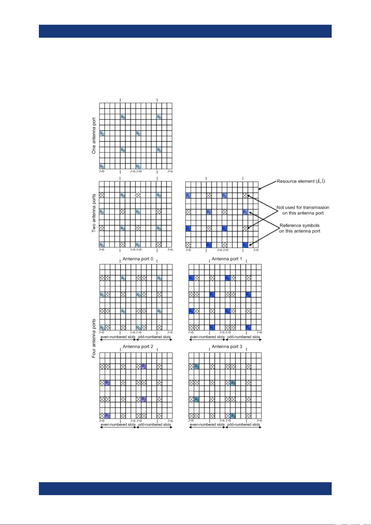
About the EUTRA/LTE optionsEUTRA/LTE/IoT
Introduction to the EUTRA/LTE technology
AP 3). Specific predefined resource elements in the time-frequency domain carry the
reference signal sequence. Besides first reference symbols, there can be a need for
second reference symbols. The different colors in the figure represent the sequences
transmitted from up to four transmit antennas.
Figure 2-9: Downlink reference signal structure (normal cyclic prefix)
28User Manual 1178.8194.02 ─ 09

About the EUTRA/LTE optionsEUTRA/LTE/IoT
Introduction to the EUTRA/LTE technology
The reference signal sequence carries the cell identity. There are 504 unique physical
layer cell identities, grouped into 168 unique physical cell identity groups that contain
three unique identities each. Each reference signal is generated as a pseudo-random
sequence that depends on the physical layer cell identity.
Frequency hopping can be applied to the downlink reference signals. The frequency
hopping pattern has a period of one frame (10 ms).
During cell search, the handset identifies different types of information: symbol and
radio frame timing, frequency, cell identification, overall transmission bandwidth,
antenna configuration, and cyclic prefix length.
Besides the reference signals, synchronization signals are therefore needed during cell
search. EUTRA uses a hierarchical cell search scheme similar to WCDMA. This
means that the synchronization acquisition and the cell group identifier are obtained
from different SYNC signals. Thus, a primary synchronization signal (P-SYNC or PSS)
and a secondary synchronization signal (S-SYNC or SSS) are defined with a predefined structure. They are transmitted on the 72 center subcarriers (around DC subcarrier) within the same predefined slots (twice per 10 ms) on different resource elements, see Figure 2-10. This figure is taken from TS 36.211.
Figure 2-10: P-SYNC and S-SYNC structure (normal CP; 1.25 MHz bandwidth)
As additional help during cell search, a common control physical channel (CCPCH) is
available which carries BCH type of information, e.g. system bandwidth. It is transmitted at predefined time instants on the 72 subcarriers centered on the DC subcarrier.
To enable the UE to support this cell search concept, it was agreed to have a minimum
UE bandwidth reception capability of 20 MHz.
Related settings
See "Synchronization Signal Settings" on page 102.
MBSFN reference signals
MBSFN reference signals are defined fro extended cyclic prefix only. The MBSFN reference signals are transmitted on antenna port 4 (AP 4) and only when the PMCH is
transmitted.
The Figure 2-11 shows the resource elements used by the MBSFN reference signal if
Δf=15 kHz .
29User Manual 1178.8194.02 ─ 09

About the EUTRA/LTE optionsEUTRA/LTE/IoT
Introduction to the EUTRA/LTE technology
Figure 2-11: MBSFN reference signal structure (extended cyclic prefix, carrier spacing 15 KHz)
Related settings
See Chapter 4.2.3, "MBSFN settings", on page 78.
UE-specific reference signal (DMRS)
These reference signals are intended for a specific user and mapped to predefined
PDSCH RBs of this particular user. The resource elements predefined for the UE-specific RS do not overlap with the resource elements reserved for the cell-specific reference signals.
For single-antenna transmission, the UE-specific reference signals are transmitted on
antenna port 5, 7 or 8 (AP 5, AP 7, and AP 8). If a spatial multiplexing is applied, the
UE-specific reference signals are transmitted on antenna ports 7 to 10 (AP 7 to AP 10).
The UE-specific RS are also called demodulation reference signals (DMRS) and are
intended for channel estimation and demodulation instead of the common reference
signals. One typical example of the application of UE-specific RS is the channel estimation and demodulation, if beamforming transmission is used. This is also called
transmission using antenna port 5 (AP 5).
In contrary to the common reference signals that are not precoded, the UE-specific RS
are precoded in the same way as the PDSCH they are mapped to.
See Figure 2-12 and Figure 2-13 for illustration of the mapping of the UE-specific reference signals to the resource elements.
30User Manual 1178.8194.02 ─ 09

About the EUTRA/LTE optionsEUTRA/LTE/IoT
Introduction to the EUTRA/LTE technology
Figure 2-12: UE-specific reference signals, antenna port 5 (normal cyclic prefix)
Figure 2-13: UE-specific reference signals, antenna ports 7 to 10 (normal cyclic prefix, downlink sub-
frame)
See also "Transmission mode TM10 and DCI format 2D" on page 52.
Positioning reference signals
The positioning reference signals are transmitted only in downlink subframes configured for positioning reference signals transmission. Positioning reference signals are
transmitted on antenna port 6 (AP 6).
The Figure 2-14 shows the mapping of the positioning reference signals for the one
and two PBCH antenna ports case (normal cyclic prefix). Refer to the specification for
information about the mapping in all other cases.
31User Manual 1178.8194.02 ─ 09

About the EUTRA/LTE optionsEUTRA/LTE/IoT
Introduction to the EUTRA/LTE technology
Figure 2-14: Mapping of PRS (normal cyclic prefix), one and two PBCH antenna ports.
Related settings
See Chapter 4.2.7.3, "Positioning reference signal (PRS) settings", on page 104 .
CSI reference signals
The CSI reference signals (CSI-RS) are intended for the acquisition of channel-state
information (CSI) for UE working in transmission mode 9 or 10 (TM9 or TM10). This is
because in TM9, the DMRS are used for channel estimation.
The CSI-RS structure depends on the number of CSI-RS (1, 2, 4 or 8) configured in a
cell and can differ between the cells. This is illustrated on Figure 2-15 [TS 36.211].
Up to LTE Rel. 13, the CSI-RS are transmitted on antenna ports 15 to 22 (AP 15 to AP
22).
From LTE Rel. 14 on, also the AP 23 to AP 46 are supported and the multiple CSI-RS
configuration mapped on them. See also Chapter 2.2.8, "LTE Release 13/14 introduc-
tion", on page 54.
R15R
15
l=0 l=6 l=0 l=6
Figure 2-15: Mapping of a CSI-RS on antenna port 15 (CSI configuration 0, normal cyclic prefix)
32User Manual 1178.8194.02 ─ 09

About the EUTRA/LTE optionsEUTRA/LTE/IoT
Introduction to the EUTRA/LTE technology
Pattern = Example of possible position of the CSI-RSs
Dark green = Example of allocated CSI-RS signals in a cell
Border = Example of muted (ZeroTxPower) CSI-RSs
The CSI-RS can be configured with different transmission periods (5 ms to 80 ms) and
per subframe (see Table 4-3).
In normal operation, the CSI-RS is transmitted on the allocated resource elements
(dark green color on Figure 2-15). The remaining possible but not allocated resource
elements (the pattern elements on the same figure) are used for PDSCH transmission.
The 3GPP specification allows the configuration of an extra subset of resource elements. These resource elements are reserved for CSI-RS transmission and have the
same structure as the CSI-RS but use a zero transmission power (ZeroTxPower).
Nothing is transmitted during these resource elements.
Related settings
See:
●
Chapter 4.2.7.4, "CSI-RS settings", on page 108
●
Chapter 4.4.2, "CSI-RS settings", on page 207
●
"CSI Awareness State" on page 135
2.2.1.6 Downlink physical layer procedures
For E-UTRA, the following downlink physical layer procedures are especially important:
●
Cell search and synchronization
See "Cell-specific downlink reference signals" on page 27.
●
Scheduling
Scheduling is done in the base station (eNodeB). The downlink control channel
PDCCH informs users about their allocated time/frequency resources and the
transmission formats to use. The scheduler evaluates different types of information,
e.g. quality-of-service parameters, measurements from the UE, UE capabilities,
and buffer status.
●
Link adaptation
Link adaptation is already known from HSDPA as adaptive modulation and coding.
Also in E-UTRA, modulation and coding for the shared data channel is not fixed,
but rather is adapted according to radio link quality. For this purpose, the UE regularly reports channel quality indications (CQI) to the eNodeB.
●
Hybrid automatic repeat request (ARQ)
Downlink hybrid ARQ is also known from HSDPA. It is a retransmission protocol.
The UE can request retransmissions of incorrectly received data packets.
2.2.2 LTE uplink transmission scheme
During the study item phase of LTE, alternatives for the optimum uplink transmission
scheme were investigated. While OFDMA is seen optimum to fulfill the LTE requirements in downlink, OFDMA properties are less favorable for the uplink. This is due to
33User Manual 1178.8194.02 ─ 09

About the EUTRA/LTE optionsEUTRA/LTE/IoT
Introduction to the EUTRA/LTE technology
weaker peak-to-average power ratio (PAPR) properties of an OFDMA signal, resulting
in worse uplink coverage.
Thus, the LTE uplink transmission scheme for FDD and TDD mode is based on SCFDMA (single carrier frequency division multiple access) with cyclic prefix. SC-FDMA
signals have better PAPR properties compared to an OFDMA signal. This was one of
the main reasons for selecting SC-FDMA as LTE uplink access scheme. The PAPR
characteristics are important for cost-effective design of UE power amplifiers. Still, SCFDMA signal processing has some similarities with OFDMA signal processing, so
parameterization of downlink and uplink can be harmonized.
There are different possibilities how to generate an SC-FDMA signal. DFT-spreadOFDM (DFT-s-OFDM) has been selected for EUTRA. The principle is illustrated on
Figure 2-16. This figure is taken from 3GPP R1-050584, "EUTRA Uplink Numerology
and Design".
For DFT-s-OFDM, a size-M DFT is first applied to a block of M modulation symbols.
QPSK, 16QAM and 64 QAM are used as uplink EUTRA modulation schemes, the latter being optional for the UE. The DFT transforms the modulation symbols into the frequency domain. The result is mapped onto the available subcarriers. In EUTRA uplink,
only localized transmission on consecutive subcarriers is allowed. An N point IFFT
where N>M is then performed as in OFDM, followed by addition of the cyclic prefix and
parallel to serial conversion.
Figure 2-16: Block diagram of DFT-s-OFDM (localized transmission)
The DFT processing is therefore the fundamental difference between SC-FDMA and
OFDMA signal generation. This is indicated by the term DFT-spread-OFDM. In an
SCFDMA signal, each subcarrier used for transmission contains information of all
transmitted modulation symbols. This due to fact that the input data stream has been
spread by the DFT transform over the available subcarriers. In contrast, each subcarrier of an OFDMA signal only carries information related to specific modulation symbols.
34User Manual 1178.8194.02 ─ 09

2.2.2.1 SC-FDMA parameterization
The EUTRA uplink structure is similar to the downlink. An uplink radio frame consists
of 20 slots of 0.5 ms each, and 1 subframe consists of 2 slots. The slot structure is
shown on Figure 2-17 (taken from TS 36.211).
About the EUTRA/LTE optionsEUTRA/LTE/IoT
Introduction to the EUTRA/LTE technology
Each slot carries
SC-FDMA symbols, where = 7 for the normal cyclic prefix and
= 6 for the extended cyclic prefix. SC-FDMA symbol number 3 (i.e. the 4th symbol
in a slot) carries the reference signal for channel demodulation.
Figure 2-17: Uplink slot structure
Also for the uplink, a bandwidth agnostic layer 1 specification has been selected. The
table below shows the configuration parameters in an overview table.
Configuration Number of symbols Cyclic prefix length in
samples
Cyclic prefix length in
μs
Normal cyclic prefix
Δf=15 kHz
Extended cyclic prefix
Δf=15 kHz
7 160 for first symbol
6 512 16.7 us
Related settings
See:
●
Chapter 4.1, "General settings", on page 62
●
Chapter 4.2.6, "TDD frame structure settings", on page 100
●
Chapter 6.2, "SC-FDMA time plan", on page 484
●
Chapter 6.3, "TDD time plan", on page 485.
2.2.2.2 Uplink data transmission
In uplink, data is allocated in multiples of one resource block. Uplink resource block
size in the frequency domain is 12 subcarriers, i.e. the same as in downlink. To simplify
the DFT design in uplink signal processing only factors 2, 3, and 5 are allowed.
The uplink transmission time interval (TTI) is 1 ms (same as downlink).
144 for other symbols
5.2 us for first symbol
4.7 us for other symbols
35User Manual 1178.8194.02 ─ 09

User data is carried on the physical uplink shared channel (PUSCH).
Related settings
See:
●
Chapter 4.6.7, "PUSCH structure", on page 238
●
Chapter 4.8.4, "Physical uplink shared channel (PUSCH)", on page 260
●
Chapter 4.9, "Enhanced PUSCH settings", on page 310
2.2.2.3 Uplink control information transmission
According to the LTE specifications, one of the following channels carries the uplink
control information depending on whether an uplink resource has been assigned to the
UE or not:
●
Physical Uplink Shared Channel (PUSCH)
●
Physical Uplink Control Channel (PUCCH)
Control information (CQI reports and ACK/NACK information related to data packets
received in the downlink) is multiplexed with the PUSCH, if the UE has been granted
with UL-SCH transmission.
About the EUTRA/LTE optionsEUTRA/LTE/IoT
Introduction to the EUTRA/LTE technology
The PUCCH carries uplink control information, e.g. CQI reports, HARQ ACK/NACK
information, or scheduling requests (SR), in case the UE has not been assigned an
UL-SCH transmission. The PUCCH is transmitted on a reserved frequency region at
the edges of the total available UL bandwidth. One PUCCH resource comprises a pair
of resource blocks within slot 0 and 1 that are located in the upper and the lower part of
the spectrum. PUCCH is allocated as shown on the Figure 2-18 [TS 36.211].
Figure 2-18: PUCCH mapping
TS 36.211 specifies seven PUCCH formats, see Table 2-4.
36User Manual 1178.8194.02 ─ 09

Table 2-4: PUCCH formats
About the EUTRA/LTE optionsEUTRA/LTE/IoT
Introduction to the EUTRA/LTE technology
PUCCH format Description Physical bits Modulation
scheme
1 Scheduling
request (SR)
1a ACK/NACK
ACK/NACK +
SR
1b ACK/NACK for
MIMO
ACK/NACK +
SR
2 CQI
CSI + ACK/
NACK
2a CSI + ACK/
NACK
2b CSI + ACK/
NACK for
MIMO
*)
3
ACK/NACK (if
DL carrier
aggregation
with more than
2 cells)
ACK/NACK +
SR
0 - 2, 3, 4 2, 3
1 BPSK 2, 3, 4 2, 3
2
4
20 QPSK 1, 5 3
21 QPSK+BPSK 1, 5 -
22 QPSK+QPSK 1, 5 -
48 QPSK 1, 5 3
QPSK 2, 3, 4 2, 3
ODFM symbols used for
DMRS
(normal CP)
ODFM symbols used for
DMRS
(extended CP)
4 and 5 ACK/NACK (if
DL carrier
aggregation
with more than
5 cell)
*)
eMTC does not support PUCCH formats 3, 4 and 5
Depends on RB
size (number of
used subcarriers and for F4
also number of
RBs), CP and
PUCCH format
QPSK 3 2
The different PUCCH formats are mapped to the reserved PUCCH region. The mapping is performed so that there can be only one resource block per slot that supports a
combination of PUCCH formats 1/1a/1b and 2/2a/2b.
For simultaneous transmission of multiple users on the PUCCH, different PUCCH
resource indices are used. Multiple UEs are distinguished within one resource block by
using different cyclic shifts (CS) of the CAZAC (constant amplitude zero auto-correlation) sequence. For PUCCH formats 1/1a/1b, three different orthogonal cover sequences (OC) can also be used. For the different PUCCH formats, different number of
PUCCH resource indices are available within a resource block (see Table 2-5). The
actual number of the used orthogonal sequences is also determinated by the parameter delta_shift, used to support working in different channel conditions.
37User Manual 1178.8194.02 ─ 09

About the EUTRA/LTE optionsEUTRA/LTE/IoT
Introduction to the EUTRA/LTE technology
Table 2-5: PUCCH resource indices per PUCCH format
PUCCH format PUCCH resource indices Number available within a
resource block
1/1a/1b N(1)_PUCCH 36 for normal CP
24 for extended CP
2/2a/2b N(2)_PUCCH 12
*)
3
*)
4
*)
5
*)
eMTC does not support PUCCH formats 3, 4 and 5
N(3)_PUCCH 5
N(4)_PUCCH 1
N(5)_PUCCH 3
Related settings
See:
●
Chapter 4.6.8, "PUCCH structure", on page 239
●
Chapter 4.10, "Enhanced PUCCH settings", on page 320
2.2.2.4 Uplink reference signal structure
Uplink reference signals are used for two different purposes:
●
For channel estimation in the eNodeB receiver to demodulate control and data
channels
●
To provide channel quality information as a basis for scheduling decisions in the
base station.
This purpose is also called channel sounding.
The uplink reference signals are based on CAZAC (constant amplitude zero auto-correlation) sequences.
Sounding reference signals (SRS)
The specification defines two types of sounding reference signals (SRS), periodic SRS
and aperiodic SRS. A user equipment (UE) can be configured with both SRS trigger
types.
●
Periodic SRS occurs at regular time intervals.
It is referred as "trigger type 0" SRS and is known form LTE Rel. 8
●
The aperiodic SRS transmission is a single (one-shot) transmission
It is referred as "trigger type 1" SRS and is introduced by LTE Rel. 10.
Aperiodic SRS is triggered by the "SRS Request" flag in one of the DCI formats
0/1A/4/2B/2C/2D.
Triggering aperiodic SRS by using DCI format 0 requires one dedicated SRS set of
parameters whereas the triggering by using DCI formats 1A/2A/2B/2C uses a common SRS set. For the triggering by DCI format 4, the specification defines three
SRS sets.
38User Manual 1178.8194.02 ─ 09
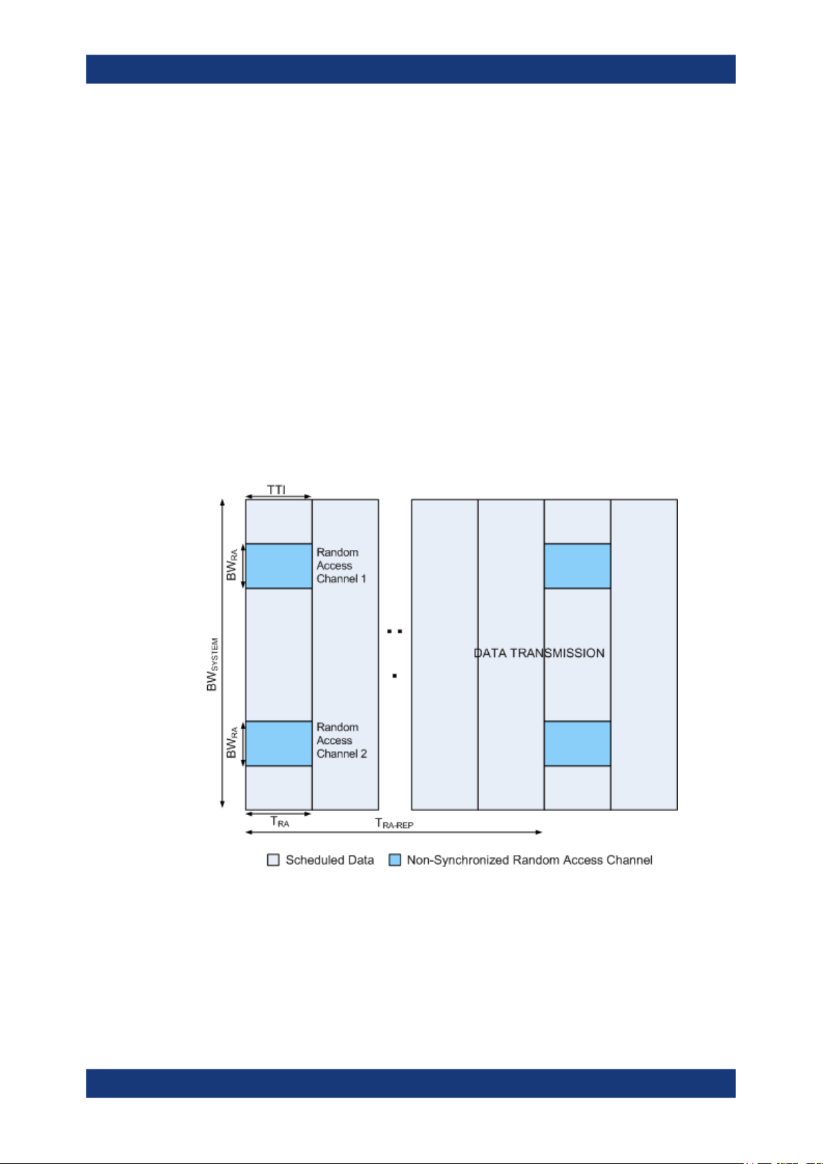
Related settings
See:
●
Chapter 4.6.5.1, "UL reference signals", on page 232
●
Chapter 4.6.5.2, "Cell-specific SRS settings", on page 234
●
Chapter 4.8.6, "Sounding reference signal (SRS)", on page 267
●
"Aperiodic SRS State" on page 135
●
"DCI Format 1A" on page 191
2.2.2.5 Uplink physical layer procedures
For EUTRA, the following uplink physical layer procedures are especially important:
Non-synchronized random access
The random access is used to request initial access, as part of handover, when transiting from idle to connected, or to re-establish uplink synchronization. The structure is
shown on Figure 2-19 (taken from TS 36.211).
About the EUTRA/LTE optionsEUTRA/LTE/IoT
Introduction to the EUTRA/LTE technology
Figure 2-19: Random access structure, principle
Multiple random access channels can be defined in the frequency domain within one
access period TRA to provide enough random access opportunities.
For the random access, a preamble is defined as shown on Figure 2-20 (taken from TS
36.211). The preamble length depends on the preamble format. The preamble band-
width is 1.08 MHz (72 subcarriers). Higher layer signaling controls in which subframes
39User Manual 1178.8194.02 ─ 09
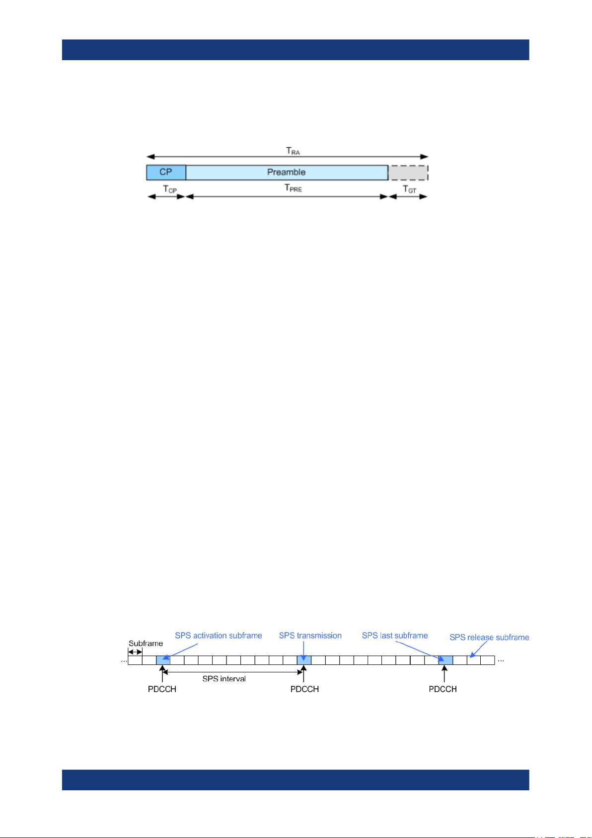
About the EUTRA/LTE optionsEUTRA/LTE/IoT
Introduction to the EUTRA/LTE technology
the preamble transmission is allowed, and the location in the frequency domain. Per
cell, there are 64 random access preambles. They are generated from Zadoff-Chu
sequences.
Figure 2-20: Random access preamble
The random access procedure uses open loop power control with power ramping similar to WCDMA. After sending the preamble on a selected random access channel, the
UE waits for the random access response message. If no response is detected, then
another random access channel is selected and a preamble is sent again.
Related settings
See:
●
Chapter 4.6.6, "PRACH settings", on page 236
●
Chapter 4.8.9, "PRACH power ramping", on page 306
●
Chapter 4.8.10, "PRACH configuration", on page 307
Uplink scheduling
As in the downlink direction, the uplink scheduling is dynamical scheduling of uplink
resources performed by eNodeB on a subframe basis. The eNodeB assigns certain
time/frequency resources to the UEs and informs UEs about transmission formats to
use. Scheduling decisions affecting the uplink are communicated to the UEs via the
physical downlink control channel (PDCCH) in the downlink. The scheduling decisions
can be based on QoS parameters, UE buffer status, uplink channel quality measurements, UE capabilities, UE measurement gaps, etc.
The LTE specification defines a second uplink scheduling method, the semi-persistent
scheduling (SPS). The semi-persistent scheduling is used to reduce the control signaling overhead for regularly occurring services and transmissions of relative small payloads. With SPS, the scheduling decisions are not transmitted every subframe but
once. Via the PDCCH, the UEs first receive information on the SPS periodicity, that is
information about the SPS pattern or the subframes on which scheduling decisions can
be transmitted. Semi-persistent scheduling is then activated and deactivated by an
explicit trigger, the SPS C-RNTI. The dynamic scheduling commands have higher priority than the SPS.
Figure 2-21: Semi-persistent scheduling (SPS)
40User Manual 1178.8194.02 ─ 09

About the EUTRA/LTE optionsEUTRA/LTE/IoT
Introduction to the EUTRA/LTE technology
In carrier aggregation transmission, SPS is allowed only on the primary component
carrier.
Related settings
See Chapter 4.3.7, "SPS configuration settings", on page 152.
Uplink link adaptation
As uplink link adaptation methods, transmission power control, adaptive modulation
and channel coding rate, and adaptive transmission bandwidth can be used.
Uplink timing control
Uplink timing control is required to time align the transmissions from different UEs with
the receiver window of the eNodeB. The eNodeB sends the appropriate timing-control
commands to the UEs in the downlink, commanding them to adapt their respective
transmit timing.
Hybrid automatic repeat request (ARQ)
The eNodeB uses the uplink hybrid ARQ protocol to request retransmissions of incorrectly received data packets.
2.2.3 LTE MIMO concepts
Multiple Input Multiple Output (MIMO) systems form an essential part of LTE to achieve
the ambitious requirements for throughput and spectral efficiency. MIMO refers to the
use of multiple antennas at the transmitter and at the receiver.
2.2.3.1 Downlink MIMO
For the LTE downlink, a 2x2 configuration for MIMO is assumed as baseline configuration, i.e. two transmit antennas at the base station and two receive antennas at the terminal. Configurations with four or more antennas are also being considered.
Different MIMO modes are envisaged. It has to be differentiated between spatial multiplexing and transmit diversity, and it depends on the channel condition which scheme
to select.
Related settings
See:
●
Chapter 4.2.8, "Antenna ports settings", on page 124
●
Chapter 4.4.1, "Precoding settings", on page 202
●
Chapter 4.5, "DL antenna port mapping settings", on page 211.
Spatial multiplexing
Spatial multiplexing allows transmitting different streams of data simultaneously on the
same downlink resource blocks (see Figure 2-22 for illustration of the principle). These
41User Manual 1178.8194.02 ─ 09

About the EUTRA/LTE optionsEUTRA/LTE/IoT
Introduction to the EUTRA/LTE technology
data streams can belong to one single user (single user MIMO / SU-MIMO) or to different users (multi-user MIMO / MU-MIMO). While SU-MIMO increases the data rate of
one user, MU-MIMO allows increasing the overall capacity.
Spatial multiplexing is only possible if the mobile radio channel allows it.
Figure 2-22: Spatial multiplexing
In the Figure 2-22, each transmit antenna transmits a different data stream. Each Rx
antenna receives the data streams from all transmit antennas. The channel (for a specific delay) can thus be described by the following channel matrix H:
In this general description, Nt is the number of transmit antennas, Nr is the number of
receive antennas, resulting in a 2x2 matrix for the baseline LTE scenario. The coeffi-
cients hij of this matrix are called channel coefficients from transmit antenna j to receive
antenna i, thus describing all possible paths between the transmitter and the receiver.
The number of data streams that can be transmitted in parallel over the MIMO channel
is given by min {Nt, Nr}. It is limited by the rank of the matrix H. The transmission qual-
ity degrades significantly in case the singular values of matrix H are not sufficiently
strong. This can happen in case the two antennas are not sufficiently de-correlated, for
example in an environment with little scattering or when antennas are too closely
spaced.
Codewords and spatial layers
A block of information bits that can be separately processed before it is transmitted in a
subframe, is called codeword [17].
A spatial layer indicates the number of spatial streams that can be simultaneously
transmitted [17]. The number of layers for transmission is less than or equal to the
number of transmit antenna ports and depends on the rank of the matrix H.
42User Manual 1178.8194.02 ─ 09

About the EUTRA/LTE optionsEUTRA/LTE/IoT
Introduction to the EUTRA/LTE technology
In LTE Rel. 8/9, up to two codewords can be transmitted simultaneously and mapped
onto up to four layers. There is a fixed mapping between codewords to layers, see Fig-
ure 2-23.
Figure 2-23: Codeword to layer mapping for downlink spatial multiplexing (LTE Rel. 8/9)
Precoding
Precoding on transmitter side is used to support spatial multiplexing, see Figure 2-24
(from TS 36.211). This is achieved by applying a precoding matrix W to the signal
before transmission.
Figure 2-24: Precoding principle
The optimum precoding matrix W is selected from a predefined "codebook" which is
known at the eNodeB and at the UE. Unitary precoding is used, i.e. the precoding
matrices are unitary: WHW = I. The UE estimates the radio channel and selects the
optimum precoding matrix. The optimum precoding matrix is the one which offers maximum capacity. The UE provides feedback on the uplink control channel regarding the
preferred precoding matrix (precoding vector as a special case). Ideally, this information is made available per resource block or at least group of resource blocks, since
the optimum precoding matrix varies between resource blocks. The Figure 2-25 (from
TS 36.211) gives an overview of EUTRA downlink baseband signal generation includ-
ing the steps relevant for MIMO transmission.
Figure 2-25: Overview of downlink baseband signal generation
43User Manual 1178.8194.02 ─ 09

About the EUTRA/LTE optionsEUTRA/LTE/IoT
Introduction to the EUTRA/LTE technology
Transmission modes
LTE defines the following transmission modes for the PDSCH (TS 36.213).
Table 2-6: Downlink transmission modes overview
Transmission mode Transmission scheme
Tx Mode 1 Single-antenna transmission (AP 0); SISO/SIMO but no MIMO
Tx Mode 2 Transmit diversity
●
Tx Mode 3
Tx Mode 4
Tx Mode 5
Tx Mode 6
Tx Mode 7 Single-antenna port transmission (AP 5); single layer beamforming
Transmit diversity
●
Open-loop spatial multiplexing with large delay CDD; SU-MIMO (single user MIMO)
●
Transmit diversity
●
Closed-loop spatial multiplexing; SU-MIMO
●
Transmit diversity
●
MU-MIMO (multi-user MIMO)
●
Transmit diversity
●
Closed-loop spatial multiplexing using a single transmission layer
●
Tx Mode 8
Tx Mode 9 Multi-layer transmission (AP 9 to AP 14); MU-MIMO, SU-MIMO, 8 layer
Tx Mode 10 Multi-layer transmission (AP 9 to AP 14), CoMP (coordinated multi-point
Dual layer transmission (AP 7 and AP 8); dual layer beamforming
●
Single-antenna port (AP 7 or AP 8)
beamforming
operation)
See also "Mapping of reference signals to antenna ports" on page 26.
Transmit diversity
Instead of increasing data rate or capacity, MIMO can be used to exploit diversity. If the
channel conditions do not allow spatial multiplexing, a transmit diversity scheme is
used instead, so switching between these two MIMO modes is possible depending on
channel conditions. Transmit diversity is used when the selected number of streams
(rank) is one.
Beamforming
The beamforming is a method to shape the transmitted signal in the receiver's direction. In LTE, the beamforming is defined as transmission mode 7, 8 and 9 (Tx Mode
7/8/9). Beamforming uses the special antenna ports 5 and 7 to 14, see Table 2-6.
The channel estimation in a beamforming scenario is based on the UE-specific refer-
ence signal (DMRS).
2.2.3.2 Uplink MIMO
Uplink MIMO schemes for LTE differ from downlink MIMO schemes. Up to LTE Rel. 9,
only uplink MU-MIMO is specified. Multiple user terminals can transmit simultaneously
on the same resource block. This is also referred to as spatial domain multiple access
44User Manual 1178.8194.02 ─ 09

(SDMA). The scheme requires only one transmit antenna at the UE. The UEs sharing
resource blocks have to apply mutually orthogonal pilot patterns.
For information on the SU-MIMO and the LTE-Advanced MIMO concept, see Chap-
ter 2.2.5.3, "Enhanced MIMO schemes", on page 48.
2.2.4 LTE MBMS concepts
In LTE, MBMS transmission is performed as single-cell transmission or as multi-cell
transmission. In multi-cell transmission, the cells and content are synchronized to
enable for the terminal to soft-combine the energy from multiple transmissions. The
superimposed signal looks like multipath to the terminal. This concept is also known as
single frequency network (SFN). The EUTRAN can configure which cells are part of an
SFN for transmission of an MBMS service. The MBMS traffic can share carrier with the
unicast traffic or be sent on a separate carrier. For MBMS traffic, an extended cyclic
prefix is provided. Specific reference signals are used in the subframes that carry
MBMS SFN data (see "MBSFN reference signals" on page 29).
MBMS data is carried on the MBMS traffic channel (MTCH) as logical channel. The
MBMS control channel MCCH carries the MBMS control information. Both logical
channels, the MTCH and the MCCH, are mapped onto the physical multicast channel
PMCH in the multi-cell transmission case. If a single-cell transmission is used, they are
mapped on the PDSCH.
About the EUTRA/LTE optionsEUTRA/LTE/IoT
Introduction to the EUTRA/LTE technology
Related settings
See Chapter 4.2.3, "MBSFN settings", on page 78.
2.2.5 LTE Release 10 (LTE-Advanced) introduction
This description gives a brief description only of the LTE-A features currently covered
by the software option R&S SMBVB-K85. The full set of LTE-Advanced features is
described in 1MA232.
For a complete LTE-Advanced technology introduction and an insight description of the
LTE-A features, refer to:
●
White Paper 1MA169 "LTE-Advanced Technology Introduction"
●
Application Note 1MA166 "LTE-Advanced Signals Generation and –Analysis"
2.2.5.1 Carrier aggregation
The LTE-A Rel. 10 specification uses the aggregation of multiple LTE carriers. Two or
more component carriers (CC) are grouped to support wider transmission bandwidths
of up to 100 MHz. To an LTE Rel. 8 terminal, each component carrier appears as an
LTE carrier. An LTE Rel. 10 terminal can exploit the total aggregated bandwidth. As
backward compatibility is fulfilled, a LTE-Advanced cell can serve both LTE Rel. 8 and
LTE Rel. 10 terminals simultaneously.
45User Manual 1178.8194.02 ─ 09
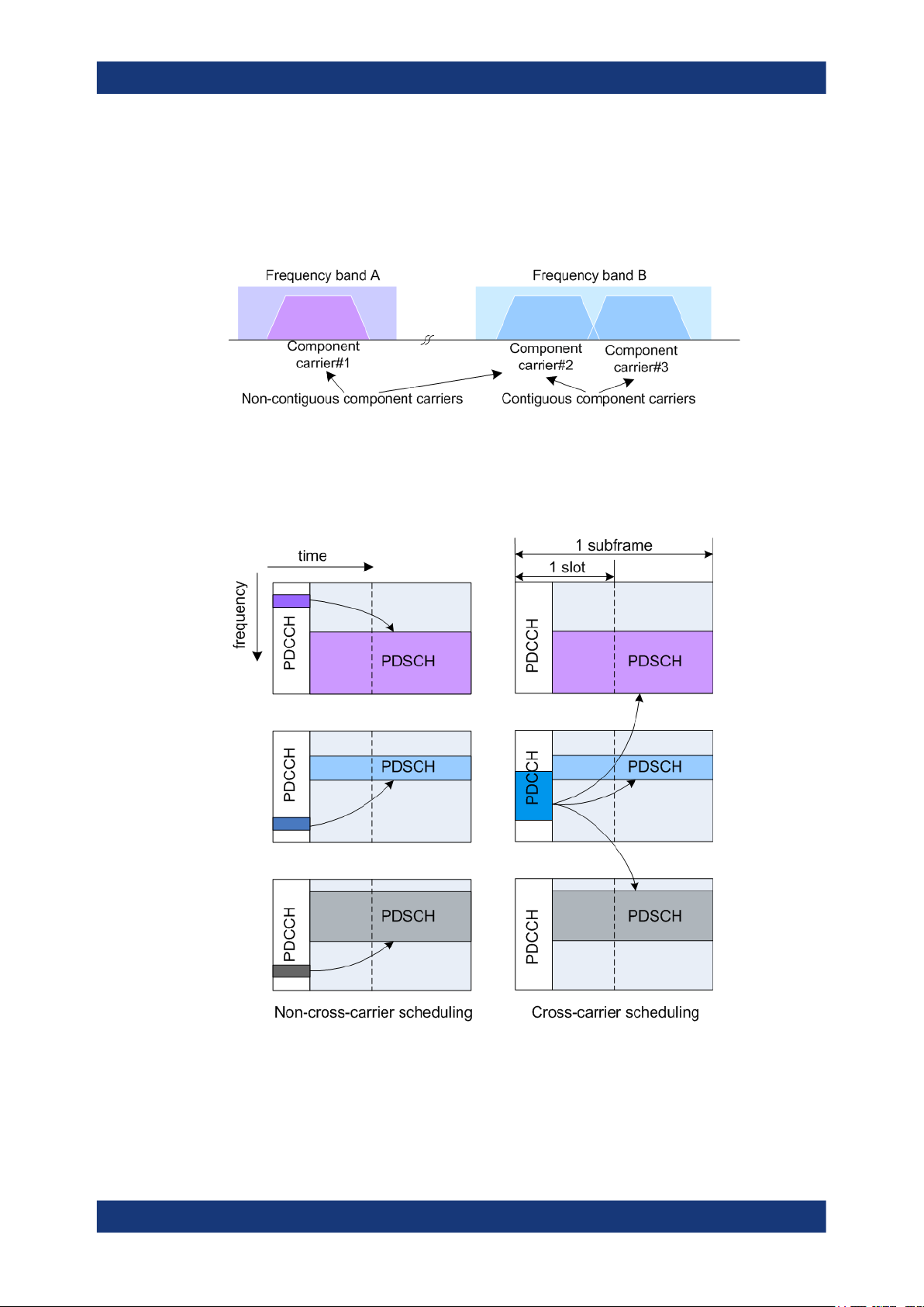
About the EUTRA/LTE optionsEUTRA/LTE/IoT
Introduction to the EUTRA/LTE technology
Spectrum deployment can be either contiguous with adjacent component carriers, or
non-contiguous with non-adjacent component carriers (see Figure 2-26, 1MA169). The
individual component carriers can belong to the same frequency band (intra-band) or
to different frequency bands (inter-band). Component carriers transmitted by the same
eNodeB provide the same cell coverage.
Figure 2-26: Carrier aggregation
The LTE-A specification defines two different approaches about informing the UE about
the scheduling for each band: a separate PDCCH for each carrier or a common
PDCCH for multiple carriers (cross-carrier scheduling).
Figure 2-27: LTE-A scheduling approaches
In the dedicated/non-cross-carrier approach, the PDCCH on a component carrier
assigns PDSCH resources on the same component carrier. The used PDCCH structure is identical to the LTE Rel. 8/9 PDCCH structure.
46User Manual 1178.8194.02 ─ 09
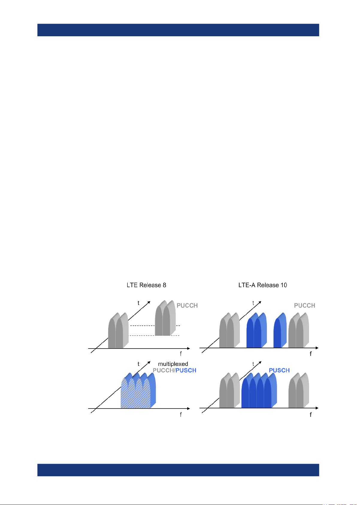
In the cross-carrier approach, the PDCCH on a component carrier assigns resources
on one of multiple component carriers. The component carriers are identified by the
new introduced DCI field, the CIF (carrier indicator field).
Related settings
See:
●
Chapter 4.2.2, "DL carrier aggregation configuration", on page 71.
●
Chapter 4.3, "DL frame configuration settings", on page 126.
●
Chapter 4.3.3, "User configuration settings", on page 129.
2.2.5.2 Enhanced uplink SC-FDMA
The LTE-A Rel. 10 enhances the uplink transmission scheme compared to the LTE
Rel. 8 uplink with the following:
●
Control-data decoupling
In LTE Rel. 8/9, a UE only uses physical uplink control channel (PUCCH) when it
does not have any data to transmit on PUSCH. If a UE has data to transmit on
PUSCH, it would multiplex the control information with data on PUSCH. This
behavior is not valid in LTE-Advanced, which means that simultaneous PUCCH
and PUSCH transmission is possible in uplink direction.
●
Non-contiguous data transmission
LTE-Advanced extends the uplink transmission scheme by allowing clustered
PUSCH. The uplink transmission is not restricted to the use of consecutive subcarriers. Clusters of resource blocks can be allocated (two "sets" of consecutive
PUSCH resource block groups according to resource allocation type 1 as defined
in TS 36.213).
About the EUTRA/LTE optionsEUTRA/LTE/IoT
Introduction to the EUTRA/LTE technology
Figure 2-28: LTE Release 8 and LTE-A Release 10 UL transmission schemes
47User Manual 1178.8194.02 ─ 09

Related settings
See:
●
Chapter 4.7, "UL frame configuration settings", on page 242
●
Chapter 4.8, "User equipment configuration", on page 252.
2.2.5.3 Enhanced MIMO schemes
LTE Rel. 8 supports MIMO schemes in downlink direction. In downlink direction, up to
four transmit antennas can be used whereas the maximum number of codewords is
two irrespective of the number of antenna ports. LTE-Advanced extends the MIMO
capabilities of LTE Rel. 8/9 to now supporting eight downlink antennas (8x8 antenna
configuration) and four uplink antennas (4x4 antenna configuration), see Figure 2-29,
and Figure 2-30, 1MA169.
About the EUTRA/LTE optionsEUTRA/LTE/IoT
Introduction to the EUTRA/LTE technology
Figure 2-29: Supported transmit layers in LTE-Advanced (downlink)
Figure 2-30: Supported transmit layers in LTE-Advanced (uplink)
48User Manual 1178.8194.02 ─ 09

About the EUTRA/LTE optionsEUTRA/LTE/IoT
Introduction to the EUTRA/LTE technology
In addition to the spatial multiplexing schemes, transmit diversity is possible in both
downlink and uplink direction.
Downlink MIMO
The following is a list of the main differences compared to LTE Rel. 8/9:
●
Layer mapping for downlink spatial multiplexing that uses the AP 7 to AP 14 for up
to 8 layer PDSCH
See "Mapping of reference signals to antenna ports" on page 26 and Figure 2-23
●
Scheduling of downlink resources uses the DCI format 2C and transmission mode
9 (TM9)
See "Transmission modes" on page 44
●
Introduced are the PDSCH demodulation reference signals DMRS
See "UE-specific reference signal (DMRS)" on page 30
●
Channel state estimation reference signals (CSI-RS)
See "CSI reference signals" on page 32
Uplink MIMO
The following is a list of the main difference compared to LTE Rel. 8/9:
●
PUSCH transmission uses up to two codewords, up to four layers and up to four
antenna ports to support SU-MIMO
●
If two PUSCH codewords are used, these codewords can use different modulation
schemes
●
Defined are different codebooks depending on the used number of antenna ports
and layers
Figure 2-31: Codeword to layer mapping for uplink spatial multiplexing (LTE Rel. 10)
●
PUCCH can be transmitted on up to two antenna ports
●
SRS can be transmitted on up to four antenna ports
See Table 2-7
Table 2-7: Uplink transmission modes overview
Transmission mode Transmission scheme
Tx Mode 1 No spatial multiplexing; transmission on a single antenna port
Tx Mode 2 Spatial multiplexing
49User Manual 1178.8194.02 ─ 09

Related settings
See:
●
Chapter 4.7.3, "UL allocation table", on page 247
●
Chapter 4.8.2, "Physical uplink control channel (PUCCH)", on page 255,
Chapter 4.8.4, "Physical uplink shared channel (PUSCH)", on page 260,
Chapter 4.8.5, "Demodulation reference signal (DMRS)", on page 265,
Chapter 4.8.6, "Sounding reference signal (SRS)", on page 267 and
Chapter 4.8.8, "Antenna port mapping", on page 303
●
Chapter 4.9, "Enhanced PUSCH settings", on page 310
●
Chapter 4.10, "Enhanced PUCCH settings", on page 320
2.2.6 LTE Release 11 introduction
This section gives a brief description only of the LTE-A Rel. 11 features currently covered by the software option R&S SMBVB-K112.
For a complete LTE-Advanced (3GPP Rel. 11) technology introduction and an insight
description of the LTE-A features, refer to:
●
White Paper 1MA232 "LTE-Advanced (3GPP Rel. 11) Technology Introduction"
About the EUTRA/LTE optionsEUTRA/LTE/IoT
Introduction to the EUTRA/LTE technology
LTE carrier aggregation enhancements
LTE-Advanced 3GPP Rel. 11 introduces the following new features:
●
Multiple timing advances (TA) for uplink carrier aggregation
●
Non-contiguous intra-band carrier aggregation
●
Two special subframe configurations for LTE TDD
– Special subframe configuration 9 with normal cyclic prefix in downlink
– Special subframe configuration 7 with extended cyclic prefix in downlink
●
Support of different UL/DL configurations on different bands
If TDD carrier aggregation is used, the individual carriers can use different UL/DL
configurations
●
Enhanced TxD schemes for PUCCH format 1b with channel selection
New control channel: enhanced PDCCH (EPDCCH)
LTE-Advanced 3GPP Rel. 11 introduces the new downlink control channel to support
new features and to increase the control channel capacity.
The enhanced physical downlink control channel (EPDCCH) carries the downlink control information. Compared to the PDCCH, the EPDCCH is not allocated on the first
symbols of a subframe as it is with PDCCH but uses resource blocks normally
reserved for the PDSCH.
50User Manual 1178.8194.02 ─ 09

About the EUTRA/LTE optionsEUTRA/LTE/IoT
Introduction to the EUTRA/LTE technology
EPDCCH is a user-specific control channel. It is always transmitted in an EPDCCH set.
For each component carrier and user, you can define one or two EPDCCH sets. Each
EPDCCH set consists of 2, 4 or 8 physical resource block (PRB) pairs that do not have
to be contiguous in frequency.
Each PRB pair consists of a number of enhanced control channel elements (ECCE).
Each ECCE consists of 4 or 8 enhanced resource element groups (EREG), where
there are 16 EREG per PRB pair. If the subsequent EREGs are allocated within a single PRB pair, the EPDCCH transmission is referred as localized. Opposite, if the
EREGs are distributed over several PRB pairs, the transmission is referred as distributed. The two different transmission schemes can be used depending on the availability of reliable channel feedback and knowledge about the channel state conditions. Distributed transmission for instance can be used to exploit frequency diversity.
DMRSs associated with EPDCCH are transmitted on antenna ports AP 107 to AP 110.
In the resource blocks mapping grid, these APs replace the AP 7 to AP 10 used for
DMRS. See also Figure 2-13.
DMRSs for EPDCCH are scrambled with higher layer user-specific identifier
EPDCCH
n
, where m = 0 or 1 and indicates the EPDCCH set.
ID,m
Related settings
See:
●
Chapter 4.3.5, "EPDCCH configuration settings", on page 146
●
"(E)PDCCH" on page 185
●
DCI Format 2/2A/2B/2C/2D > "HARQ-ACK Resource Offset"
Coordinated multi-point operation for LTE (CoMP)
CoMP is a new interference mitigation technique that aims to improve coverage of high
data rates and increase cell-edge throughput. CoMP also aims to optimize the transmission and reception from multiple transmission points (TP). A TP is a term that
describes the location, where the transmission physical occurs. TPs can be the sectors
on the same site, different remote radio heads (RRH), or different cells for example.
In CoMP scenarios, a UE can receive signals from up to 3 transmission points (TP).
During reception, the UE is unaware which of the TP is transmitting. All TPs transmit-
51User Manual 1178.8194.02 ─ 09

About the EUTRA/LTE optionsEUTRA/LTE/IoT
Introduction to the EUTRA/LTE technology
ting to a particular UE can use the same scrambling sequence for generation of the
user-specific reference signals (DMRS). The same applies for the cell-specific reference signals (CSI-RS).
According to TS 36.211, the CSI-RS sequence is generated as a function of the vari-
able N
CSI
ID
, where N
CSI
ID
= N
cell
unless configured by higher layers. The CSI-RS
ID
sequence can be initialized with the cell identity as it is in the legacy systems and if
CoMP is used, it can be initialized with "virtual cell ID". The latter is introduced to support measurements from different TPs.
According to TS 36.211, the demodulation reference signals (DMRS) for PDSCH are
generated as a function of the variable nID and n
●
Up to LTE Rel. 11, the nID = N
cell
.
ID
The DMRS sequence is initialized with the physical cell identity (PCI) N
●
In LTE Rel. 11, the following applies:
cell
or
ID
DMRS,i
are two DMRS scrambling identity.
ID
is the scrambling identity and it is n
SCID
●
–
nID = N
–
If signaled by the DCI or higher-level, nID = n
Where i = 0, 1 and n
The n
.
SCID
ID
DMRS,i
ID
= 0 or given by the corresponding
SCID
cell
.
field of DCI format 2B, 2C or 2D.
Related settings
See:
●
Chapter 4.3.6, "Scrambling configuration settings", on page 151
●
"DCI Format 2/2A/2B/2C/2D" on page 198
– DCI format 2C and 2D: "Ant. Port(s), Layers, SCID"
– DCI format 2B: "Scrambling Identity"
●
"Scrambling Identity n_SCID" on page 205
Transmission mode TM10 and DCI format 2D
The TM10 is intended for multi-layer PDSCH transmission with up to eight layers and
in case of coordinated multi-point operation (CoMP).
The transmission mode TM10 is similar to the transmission mode TM9. It uses DCI format 2D that serves the same purpose as the DCI format 2C does for the TM9. Both
formats carry the same information fields but the DCI format 2D comprises four additional bits. The first two indicate one of four pre-configured sets of parameters and are
related to the rate matching information and the QCL (quasi-co-located) indicator.
Related settings
See:
●
"Tx Modes" on page 132
●
"Transmission Scheme" on page 203
●
"DCI Format" on page 185
●
"DCI Format 2/2A/2B/2C/2D" on page 198
52User Manual 1178.8194.02 ─ 09

2.2.7 LTE Release 12 introduction
This section gives a brief description only of the LTE-A Rel. 12 features that are covered by the software option R&S SMBVB-K113.
For a complete LTE-Advanced (3GPP Rel. 12) technology introduction and an insight
description of the LTE-A features, refer to:
●
White Paper 1MA252 "LTE-Advanced (3GPP Rel. 12) Technology Introduction"
Higher-order modulation (256QAM)
TS 36.213 adds a modulation and coding scheme index table to allow signaling of the
256QAM modulation. The new modulation and coding scheme index table is referred
as MSC table 2.
Related settings
See:
●
"DL Frame Configuration" > "User Configuration" > MSC Table
●
"MBFSN" > Use Table 2 and Modulation
●
"DL Frame Configuration" > "Subframe" > Modulation
●
"DL Frame Configuration" > "Dummy Data Configuration" > Modulation
About the EUTRA/LTE optionsEUTRA/LTE/IoT
Introduction to the EUTRA/LTE technology
LTE TDD-FDD joint operation including carrier aggregation
Combination of component carriers with TDD and FDD duplexing in both the downlink
and in the uplink, including independent UL/DL configuration per component carrier.
See:
●
"General UL Settings" > "CA" > Duplexing
●
"General DL Settings" > "CA" > Duplexing
Enhanced interference mitigation & traffic adaption (eIMTA)
eIMTA (enhanced interference mitigation & traffic adaptation) is an enhancement to
LTE TDD for UL-DL interference and load management. This feature is also known as
dynamic or flexible TDD.
If eIMTA is used, an eNodeB can change the TDD pattern (TDD UL/DL Configuration)
on a frame basis and adapt the frame structure to the traffic. That is, an eNodeB can
decide to reconfigure a subset of the UL and special subframes to DL subframes. LTEAdvanced UEs that support eIMTA can receive DL transmissions in these subframes.
An eNodeB does not send an UL DCI to legacy UEs for these subframes, so that legacy UEs cannot schedule UL transmissions in these subframes.
The following layer 1 parameters are supported:
●
Dedicated eIMTA-RNTI used for CRC scrambling of the PDCCH
See "DL Frame Configuration" > "User Configuration" > eIMTA-RNTI
●
Modified DCI format 1C that indicates the UL/DL configuration numbers (1, 2, ...I).
53User Manual 1178.8194.02 ─ 09

About the EUTRA/LTE optionsEUTRA/LTE/IoT
Introduction to the EUTRA/LTE technology
Each UL/DL configuration number consist of 3 bits and corresponds to one of the
UL/DL configurations (see Figure 2-5). Each UL/DL configuration is applied for a
specific number of frames, where the number of frames is signaled by higher levels.
See "DL Frame Configuration" > "PDCCH" > "DCI Table" > DCI Format 1C for
eIMTA.
According to TS 36.212, further parameters are set by higher-level signaling.
Further DL MIMO enhancements (enhanced 4Tx codebook)
To achieve better system throughput, Rel. 12 introduces a new enhanced 4Tx codebook as one of the DL MIMO enhancements.
The enhanced 4Tx codebook is specified in TS 36.213.
Figure 2-32 shows an example of the single-layer case. For reference information on
all codebooks, see TS 36.213.
Figure 2-32: Codebook for 1-leyer CSI reporting [1MA252, TS 36.213]
See:
●
"Use Alternative Codebooks" on page 216
●
"Use Alternative Codebooks" on page 205
2.2.8 LTE Release 13/14 introduction
This section gives a brief introduction only of the LTE-A Rel. 13 features that are covered by the software option R&S SMBVB-K119.
For technical details, refer to the 3GPP Rel. 13 specifications TS 36.211, TS 36.212
and TS 36.213.
Up to LTE Rel. 12, all LTE networks use licensed spectrum bands. LTE Rel. 13 adds
among others the downlink LAA (license assisted access) functionality. It enhances the
carrier aggregation concept to use the unlicensed 5 GHz spectrum of the ISM (industrial, scientific and medical) band.
54User Manual 1178.8194.02 ─ 09

About the EUTRA/LTE optionsEUTRA/LTE/IoT
Introduction to the EUTRA/LTE technology
Figure 2-33: Carrier aggregation of licensed and unlicensed spectra [Rohde & Schwarz poster "Evo-
lution of Carrier Aggregation (3GPP Releases 10 to 13)"
Mechanisms for spectrum sharing
Since the unlicensed spectrum has to be shared fairly, LTE is extended to include the
following mechanisms:
●
Clear channel assessment (CAA) based on listen-before-talk (LTB) functionality
●
Discontinuous transmission (DTX) on a carrier with maximum channel occupancy
time (MCOT)
●
Dynamic frequency selection (DFS) for radar avoidance in certain bands
LAA SCells
Foreseen is a carrier aggregation of up to five component carriers, where the PCell
must be within the licensed spectrum. Up to four component carriers (SCells) can use
unlicensed frequency bands and span a 20 MHz channel bandwidth. Each component
carrier can use a 2x2 MIMO operation. LAA SCells support only downlink operation by
using frame structure type 3 with normal cyclic prefix (CP). LAA SCells do not support
transmission modes 5, 6 and 7 for PDSCH.
Related settings
See:
●
"General DL Settings > Carrier Aggregation" > Duplexing
2.2.8.1 Frame structure type 3 (LAA) and partial subframes
The frame structure type 3 is applicable for LAA SCells. It allows DL transmission in
bursts with burst duration of up to 10 ms, where the 10 ms correspond to the allowed
MCOT. Except from the discovery reference signal (DRS), channels cannot be sent
outside the bursts.
LAA SCell using frame structure type 3 is always regarded as FDD component carriers. Hence, depending on the duplexing mode the PCell uses, the resulting configuration is FDD only or carrier aggregation with mixed TDD-FDD component carriers.
55User Manual 1178.8194.02 ─ 09

About the EUTRA/LTE optionsEUTRA/LTE/IoT
Introduction to the EUTRA/LTE technology
Radio frames with frame structure type 3 are 10 ms, composed of 20 slots with length
of 0.5 ms each. Two consecutive slots build a subframe. Downlink transmission uses
one or more consecutive subframes, starting at the first or seventh symbol within a
subframe and ending with the last subframe. The last subframe can be either fully
occupied or following one of the DwPTS durations, specified for frame structure type 2
(see "Frame structure type 2 (TDD)" on page 22).
Figure 2-34: DL LAA burst transmission
LAA DL burst = Example of burst consisting of 3 consecutive and 2 partial subframes
PCell = LTE primary cell
MCOT = Maximum channel occupancy time ≤ 10 ms
1 ms = LTE PCell and LAA SCell slot duration
PDCCH, PDSCH = Channels are always sent within the bursts
Partial subframe = Starting at second slot boundary and ending as a DwPTS subframe
Partial subframes
LTE Rel. 13 introduces the concept of partial subframes, where the following applies:
●
Starting subframe
LAA DL burst can start at the LTE subframe boundary (subframeStartPositon)
or at the boundary of the second slot of a subframe
(secondSlotStartingPositon).
A partial starting subframe is followed by a subframe with all symbols used.
●
Ending subframe n
The last subframe of a LAA DL burst can end on the LTE subframe boundary or on
a symbol boundary as in DwPTS (endingDwPTS)
Thus, the duration of the last subframe of a DL LAA burst can consist of 14 OFDM
symbols or of 3, 6, 9, 10, 11 or 12 OFDM symbols. Where the lalter corresponds to
the Downlink Pilot Time Slot (DwPTS) structure of the TDD frame.
Ending subframe is configured by the dedicated DCI format 1C, see Chap-
ter 2.2.8.2, "DCI format 1C", on page 56.
Related settings
See:
●
"DL Frame Configuration" > LAA
2.2.8.2 DCI format 1C
DCI format 1C carries the field "Subframe Configuration for LAA" which specifies the
number of symbols to be used for transmission.
56User Manual 1178.8194.02 ─ 09

About the EUTRA/LTE optionsEUTRA/LTE/IoT
Introduction to the EUTRA/LTE technology
Assuming n is the last subframe, DCI format 1C can be sent in the following ways:
●
n or n-1:
In the next-to-last subframe (n-1) or in the last subframe n.
●
n and n-1:
If present in both, then both subframes have to use identical subframe configuration.
●
n:
If "Subframe Configuration for LAA < 14", no other physical channels are sent in
subframe n
Related settings
See:
●
"DL Frame Configuration > (E)PDCCH > DCI Table" > User
●
"DL Frame Configuration > (E)PDCCH > DCI Table > DCI Format = 1C" > DCI For-
mat 1C for LAA
2.2.8.3 Physical channels and signals in an LAA SCell
LAA SCell supports:
●
PDSCH, (E)PDCCH, CRS, CSI-RS and DRS
LAA SCell does not support:
●
PHICH, PBCH and PMCH
Discovery reference signal (DRS)
DRS is 1ms (or 12 OFDM symbols) long and is transmitted at most once in any subframe during periodical occasions refereed as DRS measurement timing configuration
(DMTC). The DMTC occasions have duration of 6 ms and a configurable period of 40
ms, 80 ms or 160 ms.
Figure 2-35: DRS allocation
DRS = Discovery reference signal
LBT = Listen-before-talk
DMTC = DRS measurement timing configuration
DRS occasion = Subframes during the DMTC period where DRS can occur
PDSCH = Physical DL shared channel
If part of DRS, PSS and SSS are always transmitted, regardless of the subframe
where the DRS occasion appears. Simultaneous transmission of DRS and PDSCH/
(E)PDCCH is allowed in subframe#0 and subframe#5.
57User Manual 1178.8194.02 ─ 09

Related settings
See:
●
"General DL Settings > Signals" > "DRS"
●
"General DL Settings > Signals > DRS" > CSI-RS > "Config"
2.2.8.4 Full dimension MIMO (FD-MIMO)
Full Dimension MIMO is a MIMO method that employs antennas capable of beam
steering in the 3D space. This 3D steering is realized by an antenna system that can
form horizontal and vertical beams.
A vertical beam steering allows for focusing on different floor of a multi-story building,
whereas horizontal beams facilities MU-MIMO transmission, as described in Chap-
ter 2.2.5.3, "Enhanced MIMO schemes", on page 48. Antenna focusing in the vertical
axis is also known as elevation beam steering; similarly, the horizontal one is referred
to as azimuth beam steering.
Precise 3D beam steering requires measuring and reporting channel state information
for each beam separately. The CSI-RS structure specified in the LTE standards up to
LTE Rel. 12 is sufficient for the MU-MIMO case but not for the requirements of the 3D
MIMO scenarios.
About the EUTRA/LTE optionsEUTRA/LTE/IoT
Introduction to the EUTRA/LTE technology
Thus, LTE Rel. 13 extends the specification to include multiple CSI-RS configurations
per cell. It also extends the range of supported antenna ports by allowing transmission
on AP 23 to AP 46. Moreover, it introduces a CDM scheme to support the mapping to
the physical resources.
According to TS 36.211, CSI reference signals are transmitted on 1, 2, 4, 8, 12, 16, 20,
24, 28, or 32 antenna ports. Since there are a total number of 32 antennas and eight
different CSI configurations, the specification limits the amount of possible combination
by applying an aggregation rule. Table 2-8 lists the possible combinations.
Table 2-8: Aggregation of CSI-RS configurations [TS 36.211]
Total number of antenna ports
CSI
N
res
12 4 3
16 8 2
20 4 5
24 8 3
28 4 7
32 8 4
*N
ports
CSI
Number of antenna ports per
CSI-RS configuration
CSI
N
ports
Number of CSI-RS configurations
CSI
N
res
Related settings
See:
●
Chapter 4.2.7.4, "CSI-RS settings", on page 108
58User Manual 1178.8194.02 ─ 09

●
Chapter 4.5, "DL antenna port mapping settings", on page 211
2.2.8.5 PUCCH formats 4 and 5
From LTE Rel. 14 on, the specification is extended with carrier aggregation of up to 32
carriers, both in the downlink and in the uplink direction. For the carrier aggregation in
uplink, two new PUCCH formats are defined, PUCCH format 4 and PUCCH format 5.
Carrier aggregation with more than 5 carriers is not supported by the current firmware
version, but you can configure the PUCCH formats. Other than in all other PUCCH formats, PUCCH format 4 spans more than one contiguous resource blocks and thus
uses larger resource block in the time domain.
For overview information on the PUCCH formats, see Chapter 2.2.2.3, "Uplink control
information transmission", on page 36.
Related settings
See:
●
"Range n(4)_PUCCH/Range n(5)_PUCCH" on page 241
●
"Number of Antenna Ports for PUCCH per PUCCH Format" on page 256
●
Chapter 4.10, "Enhanced PUCCH settings", on page 320
About the EUTRA/LTE optionsEUTRA/LTE/IoT
Introduction to the EUTRA/LTE technology
2.2.8.6 TDD special subframe configuration 10
From LTE Rel. 13 on, the specification is extended to support special subframe configuration 10, both in the downlink and in the uplink direction. The PUSCH in UpPTS follows a cell-specific configuration and can be configured independently for each user.
For overview information on the TDD frame structure, see "Frame structure type 2
(TDD)" on page 22.
Related settings
See:
●
Chapter 4.2.6, "TDD frame structure settings", on page 100
●
"TDD Special Subframe Config" on page 76
●
"TDD Special Subframe Config" on page 223
●
"PUSCH in UpPTS" on page 265
2.2.8.7 DMRS enhancements and DCI format 2C/2D
Starting from LTE Rel. 13, the transmission modes TM9 and TM10 can utilize new
antenna ports, the AP11 and AP13, for one or two-layer transmissions and for transmit
diversity.
DCI format 2C/2D carry the field "Ant. Port(s), Layers, SCID" which specifies the combination of used antenna ports, scrambling identity and number of layers (TS 36.212).
59User Manual 1178.8194.02 ─ 09

About the EUTRA/LTE optionsEUTRA/LTE/IoT
Introduction to the EUTRA/LTE technology
The value range of this field depends on the higher-layer parameters semiOpenLoop
and dmrs-tableAlt.
Related settings
See:
●
"DL Frame Configuration > General > Configure User > Tx Mode = TM9|TM10" >
DMRS Alt Table and Semi Open Loop
●
"DL Frame Configuration > (E)PDCCH > DCI Table > DCI Format = 2C/2D" > DCI
Format 2/2A/2B/2C/2D
●
"DL Frame Configuration > General > Configure User > Tx Mode = TM9|TM10 >
Antenna Mapping > Config" > User-Specific Antenna Port Mapping
●
"DL Frame Configuration > Subrame > PDSCH > Enchanced Settings > Config" >
Number of Layers, Antenna Ports and Mapping Table
60User Manual 1178.8194.02 ─ 09

Find out the implemented 3GPP specificationEUTRA/LTE/IoT
3 Find out the implemented 3GPP specifica-
tion
The Info dialog displays the currently supported version of the 3GPP standard.
Access:
► Select "EUTRA/LTE > Info".
The default settings and parameters provided are oriented towards the specifications of the version displayed.
Remote command:
[:SOURce]:BB:EUTRa:VERSion? on page 559
61User Manual 1178.8194.02 ─ 09

EUTRA/LTE configuration and settingsEUTRA/LTE/IoT
General settings
4 EUTRA/LTE configuration and settings
Access:
► Select "Baseband > EUTRA/LTE".
The remote commands required to define these settings are described in Chapter 10,
"Remote-control commands", on page 553.
● General settings......................................................................................................62
● General DL settings / general TDD DL settings......................................................68
● DL frame configuration settings............................................................................ 126
● Enhanced PBCH, PDSCH and PMCH settings.................................................... 201
● DL antenna port mapping settings........................................................................ 211
● General UL settings.............................................................................................. 217
● UL frame configuration settings............................................................................ 242
● User equipment configuration............................................................................... 252
● Enhanced PUSCH settings...................................................................................310
● Enhanced PUCCH settings...................................................................................320
4.1 General settings
Access:
► Select "Baseband > EUTRA/LTE > General".
This dialog comprises the standard general settings, to the default and the "Save/
Recall" settings, as well as setting for defining the link direction or the used duplexing mode and access to dialogs with further settings. The choice of link direction
determines which parameters are available.
Provided are the following settings:
62User Manual 1178.8194.02 ─ 09

EUTRA/LTE configuration and settingsEUTRA/LTE/IoT
General settings
State..............................................................................................................................63
Set to Default................................................................................................................ 63
Save/Recall...................................................................................................................64
Generate Waveform......................................................................................................64
Test Case Wizard..........................................................................................................64
Mode............................................................................................................................. 65
Duplexing...................................................................................................................... 65
Link Direction................................................................................................................ 65
Test Models...................................................................................................................66
General DL Settings/General UL Settings.................................................................... 68
Frame Configuration..................................................................................................... 68
Filter/Clipping/ARB/TDW/Power Settings..................................................................... 68
U-Plane Generation...................................................................................................... 68
State
Activates the standard and deactivates all the other digital standards and digital modulation modes in the same path.
Remote command:
[:SOURce<hw>]:BB:EUTRa:STATe on page 555
Set to Default
Calls the default settings. The values of the main parameters are listed in the following
table.
Parameter Values
State Not affected by "Set to Default"
Duplexing FDD
Link Direction Downlink (OFDMA)
Sequence Length 1 Frame
DL Channel Bandwidth 10 MHz
Physical Resource Block Bandwidth 12 * 15 kHz
Number Of Resource Blocks per Slot 50
Occupied Bandwidth /MHz 9.015
Sampling Rate /MHz 15.360
FFT Size 1024
Cell ID 0
Cyclic Prefix Normal
PHICH Duration Normal
Global MIMO Configuration 1 TxAntenna
Simulated Antenna Antenna 1
Remote command:
[:SOURce<hw>]:BB:EUTRa:PRESet on page 556
63User Manual 1178.8194.02 ─ 09

EUTRA/LTE configuration and settingsEUTRA/LTE/IoT
General settings
Save/Recall
Accesses the "Save/Recall" dialog, i.e. the standard instrument function for storing and
recalling the complete dialog-related settings in a file. The provided navigation possibilities in the dialog are self-explanatory.
The file name and the directory it is stored in are user-definable; the file extension is
however predefined.
See also, chapter "File and Data Management" in the R&S SMBV100B user manual.
Remote command:
[:SOURce<hw>]:BB:EUTRa:SETTing:CATalog on page 557
[:SOURce<hw>]:BB:EUTRa:SETTing:LOAD on page 557
[:SOURce<hw>]:BB:EUTRa:SETTing:STORe on page 558
[:SOURce<hw>]:BB:EUTRa:SETTing:DEL on page 557
Generate Waveform
With enabled signal generation, triggers the instrument to save the current settings of
an arbitrary waveform signal in a waveform file with predefined extension *.wv. You
can define the filename and the directory, in that you want to save the file.
Using the ARB modulation source, you can play back waveform files and/or process
the file to generate multi-carrier or multi-segment signals.
If the current configuration uses coupled baseband sources with more than one Tx
antenna (for example "System Config > Baseband (Tx Antennas) = 2"), with this function you trigger the software to generate the signals of all antennas. Created is a subset of waveform files, where the number of files corresponds to the number the currently simulated antennas and the file names have the following structure:
<user-defined file name><antenna#-1>.wv.
Example:
Select "System Config > Fading/Baseband Config > Mode > Advanced"
Select "System Config > Fading/Baseband Config > Baseband (Tx Antennas) = 4"
Select "System Config > Fading/Baseband Config > BB Source Config > Coupled"
Select "Baseband > EUTRA/LTE > General > State > On"
Select "EUTRA/LTE > General > Generate Waveform > On"
In the "Generate Waveform" dialog, use the default directory and enter "File Name =
lte".
Select [Save/Rcl], select "File/Recall > File Manager" and in the directory tree open the
default directory.
Displayed are four files, lte.wv, lte1.wv, lte2.wv and lte3.wv.
Remote command:
[:SOURce<hw>]:BB:EUTRa:WAVeform:CREate on page 558
Test Case Wizard
Accesses the "Test Case Wizard" dialog, see Chapter 7, "Performing BS tests accord-
ing to TS 36.141", on page 493.
64User Manual 1178.8194.02 ─ 09

EUTRA/LTE configuration and settingsEUTRA/LTE/IoT
General settings
Mode
In instruments equipped with options R&S SMBVB-K55 and R&S SMBVB-K115,
selects the standard to that the displayed settings belong.
If the instrument is equipped with one of these two options, the corresponding mode is
selected automatically but the parameter "Mode" is not displayed.
"Mode" Description Required options
"LTE" Standalone LTE
IoT related settings and parameters are hidden.
"eMTC/NB-IoT" Standalone IoT
Configuration of parameters specified only for
LTE is not possible.
"LTE/eMTC/NB-IoT" Mixed LTE and IoT
Allows mixed LTE and IoT configurations, for
example for interoperability tests.
R&S SMBVB-K55
(optionally also R&S SMBVB-
K85)
R&S SMBVB-K115
R&S SMBVB-K55 and
R&S SMBVB-K115
Remote command:
[:SOURce<hw>]:BB:EUTRa:STDMode on page 556
Duplexing
Selects the duplexing mode. The duplexing mode determines how the uplink and
downlink signals are separated.
"TDD"
In TDD mode, the same frequency is used for both directions of
transmission (uplink and downlink). With one baseband, either only
downlink or only uplink can be generated.
"FDD"
In FDD mode, different frequencies are used for downlink and uplink
directions.
Remote command:
[:SOURce<hw>]:BB:EUTRa:DUPLexing on page 555
Link Direction
Selects the transmission direction.
"Downlink (OFDMA)"
The transmission direction selected is base station to user equipment. The signal corresponds to that of a base station. For the downlink, the physical layer mode is always set to OFDMA.
"Uplink (SC-FDMA)"
The transmission direction selected is user equipment to base station. The signal corresponds to that of a user equipment. For the
uplink, the physical layer mode is always set to SC-FDMA.
Remote command:
[:SOURce<hw>]:BB:EUTRa:LINK on page 556
65User Manual 1178.8194.02 ─ 09

EUTRA/LTE configuration and settingsEUTRA/LTE/IoT
Test Models
Accesses a dialog for selecting of:
●
One of the EUTRA Test Models (E-TM) defined in TS 36.141
General settings
●
One of the NB-IoT Test Models (N-TM) defined in TS 36.141.
●
Self-defined test setups
Use "Recent Files" button to display the files last used.
"File Manager" button opens the dialog to load or save configuration files. See also
the section File and Data Management in the R&S SMBV100B user manual.
The DL test models are predefined configurations of LTE settings. Three main groups
of test models are defined, the E-TM1, E-TM2 and E-TM3. All test models use the following parameters:
●
Single antenna port, single codeword, single layer and no precoding
●
Duration of one frame
●
Normal cyclic prefix
●
Localized virtual resource blocks, no intra-subframe hopping for PDSCH
●
UE-specific reference signals are not used
66User Manual 1178.8194.02 ─ 09

EUTRA/LTE configuration and settingsEUTRA/LTE/IoT
General settings
The data content of the physical channels and signals is defined in the 3GPP specification. Each E-TM is defined for six different channel bandwidths: 1.4 MHz, 3 MHz, 5
MHz, 10 MHz, 15 MHz and 20 MHz. The test models are defined for specific test purpose.
EUTRA test model Defined for tests on
●
E-TM1.1
E-TM1.2
E-TM2
E-TM2a
E-TM3.1
BS output power
●
Unwanted emissions
●
Transmitter intermodulation
●
RS absolute accuracy
●
ACLR
●
Operating band unwanted emissions
●
Total power dynamic range (lower OFDM symbol power limit at min power)
●
EVM of single 64QAM PRB allocation (at min power)
●
Frequency error (at min power)
●
Total power dynamic range (lower OFDM symbol power limit at min power)
●
EVM of single 256QAM PRB allocation (at min power)
●
Frequency error (at min power)
●
Output power dynamics
●
Transmitted signal quality (Frequency error and EVM for 64QAM modulation, at max power)
●
E-TM3.1a
E-TM3.2
E-TM3.3
Output power dynamics
●
Transmitted signal quality (Frequency error and EVM for 256QAM modulation, at max power)
Transmitted signal quality:
●
Frequency error
●
EVM for 16QAM modulation
Transmitted signal quality:
●
Frequency error
●
EVM for QPSK modulation
The NB-IoT DL test models (N-TM) are predefined configurations of settings for NB-IoT
tests. Supported are the following N-TMs:
●
NB-IoT guard band operation
●
NB-IoT guard band operation in combination with LTE E-TM1.1 carriers
●
NB-IoT in-band operation, where NB-IoT and LTE use different PCIs
●
NB-IoT in-band operation, where NB-IoT and LTE share the same PCI
●
NB-IoT in-band operation in combination with LTE E-TM1.1 carriers
●
NB-IoT standalone operation
According to TS 36.141, all test models use the following parameters:
●
Single antenna port
●
Duration of 10 subframes or 10 ms
●
Normal cyclic prefix
●
The ration of synchronisation signal EPRE and NRS EPRE is 0 dB
●
NPDCCH format 1
With the option R&S SMBVB-K175 for O-RAN, the following test models in line with
3GPP TC 32.37x specifications are supported:
●
ORAN-TC32371_FDD_20MHz
●
ORAN-TC32372_FDD_20MHz
●
ORAN-TC32373_FDD_20MHz
67User Manual 1178.8194.02 ─ 09

EUTRA/LTE configuration and settingsEUTRA/LTE/IoT
General DL settings / general TDD DL settings
●
ORAN-TC32374_FDD_20MHz
●
ORAN-TC32375_FDD_20MHz
●
ORAN-TC32376_FDD_20MHz
●
ORAN-TC32376_TM3_FDD_20MHz
●
ORAN-TC32376_TM4_FDD_20MHz
Remote command:
[:SOURce<hw>]:BB:EUTRa:SETTing:TMOD:DL on page 558
[:SOURce<hw>]:BB:EUTRa:SETTing:TMOD:TDD on page 558
General DL Settings/General UL Settings
Accesses the "General DL Settings / General UL Settings" dialog for configuring the
EUTRA/LTE system.
For description of the available settings, refer to Chapter 4.2, "General DL settings /
general TDD DL settings", on page 68 and Chapter 4.6, "General UL settings",
on page 217 respectively.
Remote command:
n.a.
Frame Configuration
Accesses the "Frame Configuration" dialog for configuring the allocation of the
resource blocks to the different users, as well as the configuration of the users.
The available settings depend on the selected link direction. For description, refer to
Chapter 4.3, "DL frame configuration settings", on page 126 and Chapter 4.7, "UL
frame configuration settings", on page 242 respectively.
Remote command:
n.a.
Filter/Clipping/ARB/TDW/Power Settings
Accesses the dialog for setting baseband filtering, clipping, and the sequence length of
the arbitrary waveform component, see Chapter 9.2, "Filter/clipping/ARB settings",
on page 530.
U-Plane Generation
Option: R&S SMBVB-K175
Opens a dialog to turn user plane data generation according to the O-RAN standard on
and off.
For more information, see Chapter 8, "Generating user plane data", on page 527.
Remote command:
[:SOURce<hw>]:BB:EUTRa:UPLane:STATe on page 559
4.2 General DL settings / general TDD DL settings
The "General DL Settings" dialog allows you to configure the EUTRA/LTE system for
transmission direction downlink, i.e. the signal of one BS or one cell.
68User Manual 1178.8194.02 ─ 09
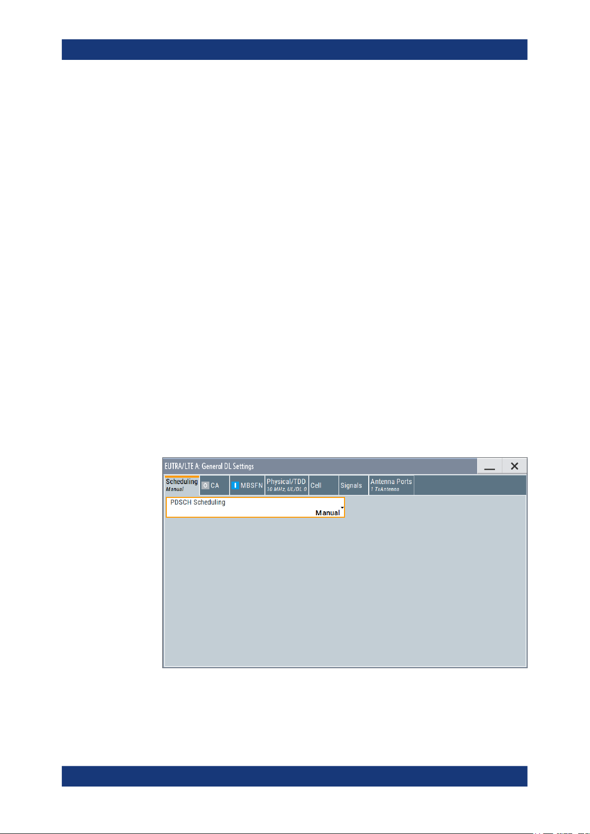
EUTRA/LTE configuration and settingsEUTRA/LTE/IoT
General DL settings / general TDD DL settings
Access:
1. Select "General > Link Direction > Downlink (OFDMA)".
2. Select "General DL Settings".
The EUTRA/LTE standard defines no differences between TDD and FDD signals
on the physical layer if only one link direction is considered at once. Therefore, the
"General TDD DL Settings" dialog comprises the same parameters as the "General
DL Settings" dialog but is extended with the TDD frame structure settings tab.
The "General DL Settings" dialog consists of several sections:
● PDSCH scheduling settings....................................................................................69
● DL carrier aggregation configuration.......................................................................71
● MBSFN settings...................................................................................................... 78
● Physical settings..................................................................................................... 92
● Cell-specific settings............................................................................................... 96
● TDD frame structure settings................................................................................ 100
● Downlink signals settings......................................................................................101
● Antenna ports settings.......................................................................................... 124
4.2.1 PDSCH scheduling settings
Access:
1. Select "General > Link Direction > Downlink (OFDMA)".
2. Select "General Settings > Scheduling".
In the "Scheduling" section, you define whether the PDSCH Scheduling is performed manually, according to the configuration made for the DCIs or according to
the required HARQ processes and redundancy versions.
69User Manual 1178.8194.02 ─ 09
EUTRA/LTE configuration and settingsEUTRA/LTE/IoT
General DL settings / general TDD DL settings
Remote command:
[:SOURce<hw>]:BB:EUTRa:DL:CONF:MODE on page 578
Overview of the scheduling methods
In the R&S SMBV100B, there are different approaches to configure and schedule the
different PDSCH allocations:
●
Manually and with full flexibility ("Manual")
This is the default scheduling mode and the mode with full flexibility; you can configure any of the available settings.
There is no cross-reference between the settings made for the PDCCH DCIs and
the PDSCHs settings. The configuration is performed on a subframe basis and you
are responsible for the content of the PDSCH allocations.
●
According to the configuration made for the DCIs ("Auto/DCI")
This is the mode supporting you to configure the precoding settings for spatial multiplexing according to TS 36.211.
This mode assures a 3GPP compliant EUTRA/LTE signal and the PDSCH allocations are configured automatically according to the configuration of the PDCCH
DCIs.
There are however limitations in the configuration flexibility, especially regarding
the power setting, see "Limitations and interdependencies in the Auto/DCI and
Auto Sequence modes" on page 70.
See also "Switching between "Auto/DCI" and "Manual" modes" on page 70.
Limitations and interdependencies in the Auto/DCI and Auto Sequence modes
The generation of a compliant signal requires some limitations in the configuration flexibility, especially regarding the power setting:
●
The value of the parameter Reference Signal Power is fixed to 0dB.
●
The PDSCH Rho A of each allocation belonging to a user is set as configured with
the parameter P_A for the corresponding user in the "Configure User" dialog.
●
All four users are activated with enabled Scrambling and Channel Coding.
●
Not all combinations of DCI Table, Users and UE_ID/n_RNTI are allowed, see
Table 4-1.
Table 4-1: DCI Formats dependencies
User UE ID/n_RNTI DCI Format
User x As defined for the corresponding user 0,1,1a,1b,1d,2,2a,2c,3,3a
P-RNTI 65534 1a,1c
SI-RNTI 65535
RA-RNTI As defined with the parameter "General DL Setting"
> RA_RNTI
Switching between "Auto/DCI" and "Manual" modes
●
Switching from "Auto/DCI" mode to "Manual"
Enables all parameters in the DL allocation table for configuration without to
change their values.
70User Manual 1178.8194.02 ─ 09

EUTRA/LTE configuration and settingsEUTRA/LTE/IoT
General DL settings / general TDD DL settings
●
Switching from "Manual" to "Auto/DCI" mode
Triggers a reset of the subframe configuration prior to reconfiguration of the
PDSCH allocations according to the settings made for the PDCCH DCIs, that is the
settings made in the DL allocation table are lost.
4.2.2 DL carrier aggregation configuration
Option: R&S SMBVB-K55 and R&S SMBVB-K85.
Access:
1. Select "General > Link Direction > Downlink (OFDMA)".
2. Select "General DL Settings > CA".
The "General DL Settings > CA" dialog provides the settings for the configuration
of one primary cell (PCell) and up to four secondary cells (SCell). In real system,
the RRC messages signal all the relevant system information for a certain SCell. In
this implementation, all relevant and configurable SCell settings are grouped in the
"Carrier Aggregation" dialog. The remaining cell-specific settings are identical for
all component carriers.
4.2.2.1 About DL carrier aggregation
This section lists implementation-related information. For background information on
this topic, refer to Chapter 2.2.5, "LTE Release 10 (LTE-Advanced) introduction",
on page 45.
In this description, the terms cell and component carrier (CC) are used interchangeably.
71User Manual 1178.8194.02 ─ 09

EUTRA/LTE configuration and settingsEUTRA/LTE/IoT
General DL settings / general TDD DL settings
SCell settings derivation
The settings of each component carrier are calculated automatically form the configured PCell settings. They depend on the parameters in the "DL Carrier Aggregation
Configuration" dialog. The following list provides an overview of the restrictions and
interdependencies between related parameters if DL carrier aggregation is enabled:
●
Combination of FDD and TDD is supported in "PDSCH Scheduling > Auto/DCI and
Auto Sequence" modes
●
Combination of TDD carriers with different UL/DL configuration or special subframe
configuration is supported in "PDSCH Scheduling > Auto/DCI and Auto Sequence"
modes
●
Simultaneous support of LTE and LTE-A users is provided
(See User configuration settings > Activate CA).
●
To enable cross-carrier scheduling, the DCI formats are extended to support the
CIF field.
The DCIs have to be configured individually per component carrier.
●
The "Control Region for PDCCH" and the PHICH parameters "PHICH Duration"
and "PHICH N_g" can have different values in the component carrier. The component carriers use different Number of PHICH Groups, because the number of
PHICH groups is calculated based on the parameter "N_g".
The cell-specific settings in the "Cell" tab correspond to the configuration of the
PCell.
●
If a SCell spans channel bandwidth with fewer RBs than the PCell, the instrument
ignores the allocations or part of the them that is outside of the SCell channel
bandwidth.
Supported LTE-A bandwidth
The LTE specification defines a maximum Channel Bandwidth of 20 MHz and aggregation of up to 5 component carriers. This achieves a 100 MHz bandwidth.
The R&S SMBV100B configured to generate more than one component carrier automatically applies the multi-carrier function. In this case, the maximum bandwidth of the
generated LTE-A signal depends on the installed options.
For more information, see data sheet.
4.2.2.2 How to enable carrier aggregation and cross-carrier scheduling
This section provides step-by-step instructions on how to use the settings to generate
an LTE-A signal.
To enable carrier aggregation and cross-carrier scheduling
In the following, a general example is provided. Only the related settings are discussed.
1. Select "Baseband > EUTRA/LTE".
72User Manual 1178.8194.02 ─ 09

EUTRA/LTE configuration and settingsEUTRA/LTE/IoT
General DL settings / general TDD DL settings
Configure the settings of the PCell as required. For example, select one of the predefined "Test Setups/Models".
2. To enable carrier aggregation:
a) Select "General DL Settings > DL Carrier Aggregation Configuration > Activate
Carrier Aggregation > On"
b) Select "DL Frame Configuration > User Configuration".
Enable "Activate CA" per user as required.
3. In the "General DL Settings > DL Carrier Aggregation Configuration > Component
Carrier Table" dialog, configure the settings of the SCells (see example on the following figure).
4. To enable cross-carrier scheduling for a certain component carrier:
a) Set the "DL Carrier Aggregation Configuration > SCell# > schedCell Index = 0"
In the example, the component carriers SCell#1, SCell#2 and SCell#4 can be
cross-scheduled over the PCell
b) Enable the "DL Carrier Aggregation Configuration > SCell# > CIF Present"
parameter.
In this example, the component carriers SCell#1 and SCell#2 is cross-scheduled over the PCell.
c) To enable a component carrier, set "DL Carrier Aggregation Configuration >
SCell# > State > On".
5. Enable LTE signal generation "EUTRA/LTE State > On".
6. If necessary, adjust the RF frequency of the path to the middle frequency of the
resulting total signal bandwidth.
73User Manual 1178.8194.02 ─ 09

7. Activate the RF output.
The instrument generates the signal in the path as multicarrier signal. The signal is
composed of three carriers, the PCell, the SCell#1 and SCell#2. Each of the component carriers spans "Channel Bandwidth = 10 MHz"; the SCells use carrier frequency offset of 20 MHz and 35 MHz.
The SCell#4 is disabled.
4.2.2.3 Carrier aggregation settings
Provided are the following settings:
Activate Carrier Aggregation.........................................................................................74
Component Carrier Table..............................................................................................74
└ Cell Index........................................................................................................74
└ Physical Cell ID...............................................................................................75
└ Bandwidth....................................................................................................... 75
└ delta f / MHz....................................................................................................75
└ Duplexing........................................................................................................75
└ TDD UL/DL Configuration...............................................................................75
└ TDD Special Subframe Config........................................................................76
└ CIF Present.....................................................................................................76
└ sched. Cell Index............................................................................................ 76
└ Enhanced Settings..........................................................................................76
└ PDSCH Start.........................................................................................76
└ PHICH N_g...........................................................................................76
└ PHICH Duration....................................................................................77
└ Power / dB...................................................................................................... 78
└ Delay / ns........................................................................................................78
└ State................................................................................................................78
EUTRA/LTE configuration and settingsEUTRA/LTE/IoT
General DL settings / general TDD DL settings
Activate Carrier Aggregation
Enables/disables the generation of several component carriers.
Remote command:
[:SOURce<hw>]:BB:EUTRa:DL:CA:STATe on page 623
Component Carrier Table
The table provides the settings of the component carriers. The first row displays the
settings of the PCell; the following four rows provide the configurable settings of the up
to four SCells.
The PCell settings resemble the settings configured in the
The PCell settings resemble the settings configured in the "General DL Settings" dia-
log.
Cell Index ← Component Carrier Table
Sets the cell index of the corresponding SCell, as specified in TS 36.331. The SCell
index is required for signaling on the DCI DCI format configuration field.
The cell index of the PCell is always 0.
74User Manual 1178.8194.02 ─ 09

EUTRA/LTE configuration and settingsEUTRA/LTE/IoT
General DL settings / general TDD DL settings
Remote command:
[:SOURce<hw>]:BB:EUTRa:DL:CA:CELL<ch0>:INDex on page 625
Physical Cell ID ← Component Carrier Table
Sets the physical Cell ID of the corresponding SCell.
The physical Cell ID of the PCell is set by the parameter "General DL Settings" > Cell
ID".
Remote command:
[:SOURce<hw>]:BB:EUTRa:DL:CA:CELL<ch0>:ID on page 624
Bandwidth ← Component Carrier Table
Sets the bandwidth of the corresponding component carrier/SCell.
Remote command:
[:SOURce<hw>]:BB:EUTRa:DL:CA:CELL<ch0>:BW on page 623
delta f / MHz ← Component Carrier Table
Sets the frequency offset between the central frequency of the SCell and the frequency
of the PCell.
Remote command:
[:SOURce<hw>]:BB:EUTRa:DL:CA:CELL<ch0>:DFReq on page 624
Duplexing ← Component Carrier Table
Selects the duplexing mode of the PCell.
●
Without R&S SMBVB-K113
The duplexing mode of the SCells is set accordingly.
●
Option: R&S SMBVB-K113
If "PDSCH Scheduling > Auto/DCI and Auto Sequence", combination of FDD and
TDD is supported
●
Option: R&S SMBVB-K119
If "PDSCH Scheduling > Auto/DCI and Auto Sequence", SCells can work in LAA
mode.
LAA cells use FDD duplexing.
Remote command:
[:SOURce<hw>]:BB:EUTRa:DL:CA:CELL<ch0>:DUPLexing on page 624
TDD UL/DL Configuration ← Component Carrier Table
Option: R&S SMBVB-K112
In TDD duplexing mode, sets the uplink-downlink configuration number. That is,
defines which subframe is used for downlink respectively uplink, and where the special
subframes are located.
In "PDSCH Scheduling > Auto/DCI and Auto Sequence" mode, the individual carriers
can use different "UL/DL Configuration". The frame configuration of the selected carries and the used duplexing are also displayed. Alternatively, use the SC-FDMA time
plan to visualize them.
Remote command:
[:SOURce<hw>]:BB:EUTRa:DL:CA:CELL<ch0>:UDConf on page 625
75User Manual 1178.8194.02 ─ 09
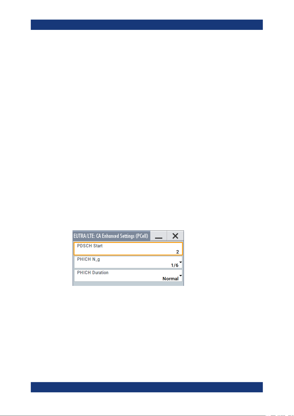
EUTRA/LTE configuration and settingsEUTRA/LTE/IoT
General DL settings / general TDD DL settings
TDD Special Subframe Config ← Component Carrier Table
Option: R&S SMBVB-K112
In TDD duplexing mode, sets the special subframe configuration number.
Together with the parameter Cyclic Prefix, this parameter defines the lengths of the
DwPTS, the guard period and the UpPTS.
Remote command:
[:SOURce<hw>]:BB:EUTRa:DL:CA:CELL<ch0>:SPSConf on page 625
CIF Present ← Component Carrier Table
Defines whether the Carrier Indicator Field (CIF) is included in the PDCCH DCI formats
transmitted from the corresponding SCell.
Remote command:
[:SOURce<hw>]:BB:EUTRa:DL:CA:CELL<ch0>:CIF on page 624
sched. Cell Index ← Component Carrier Table
Defines the component carrier/cell that signals the UL and DL grants for the selected
SCell. The signaling cell is determined by its Cell Index.
According to the LTE-A specification, cross-carrier scheduling has to be enabled per
user and per component carrier.
To enable signaling for one particular SCell on the PCell, i.e. cross-carrier scheduling,
set the "schedCell Index" to 0.
Remote command:
[:SOURce<hw>]:BB:EUTRa:DL:CA:CELL<ch0>:SCINdex on page 626
Enhanced Settings ← Component Carrier Table
Opens the "CA Enhanced Settings" dialog per component carrier.
PDSCH Start ← Enhanced Settings ← Component Carrier Table
Sets the starting symbol of the PDSCH for the component carrier and determines the
"Control Region for PDCCH".
Note: All subframes of a particular component carrier use the same "Control region for
PDCCH" as defined here, regardless of the settings of the PCell.
Remote command:
[:SOURce<hw>]:BB:EUTRa:DL:CA:CELL<ch0>:PSTart on page 626
PHICH N_g ← Enhanced Settings ← Component Carrier Table
Sets the parameter N_g according to TS 36.211, section 6.9.
76User Manual 1178.8194.02 ─ 09
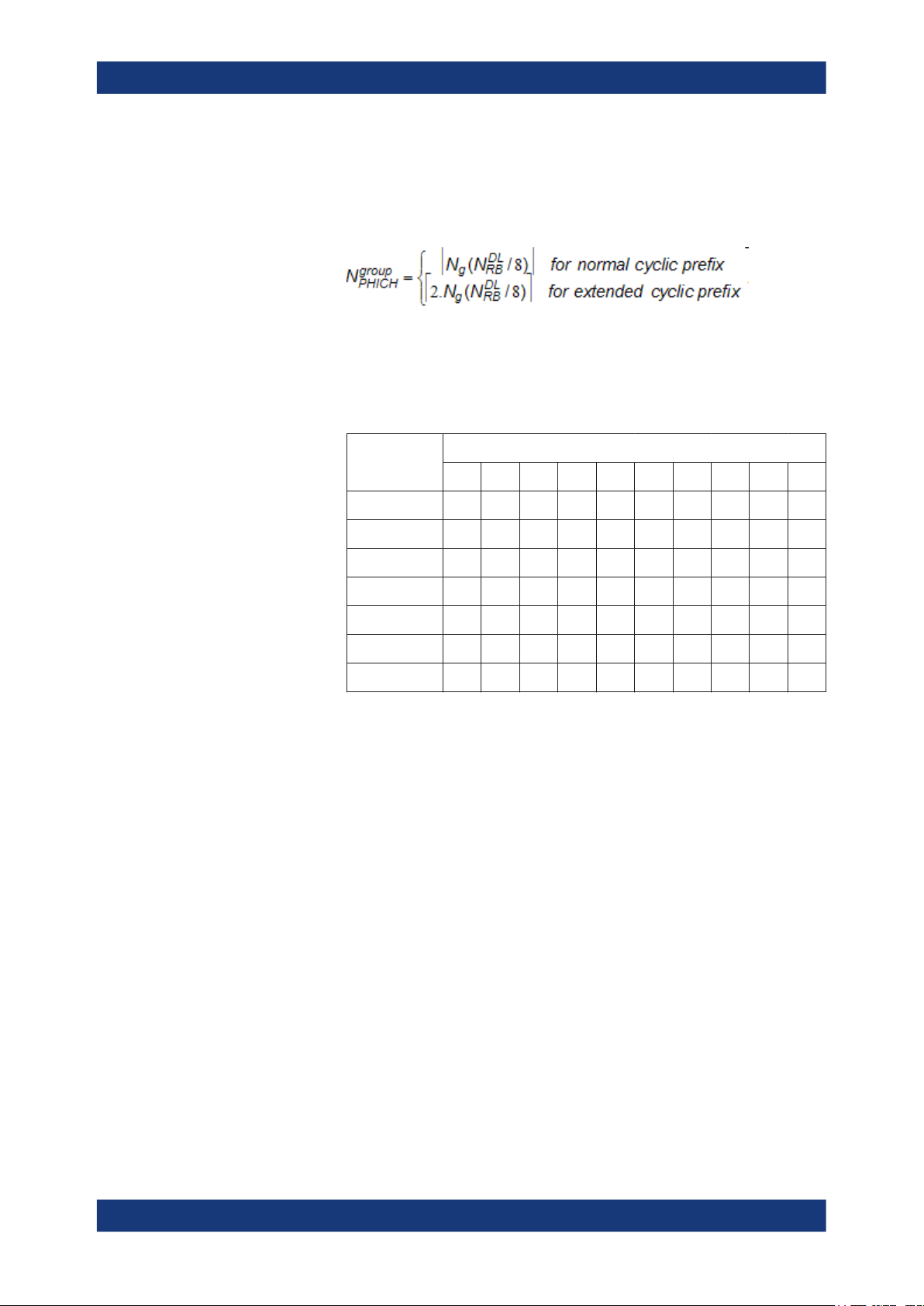
EUTRA/LTE configuration and settingsEUTRA/LTE/IoT
General DL settings / general TDD DL settings
If Activate Carrier Aggregation > "On", you can define the PHICH duration per component carrier.
"1/6, 1/2, 1, 2"
The used Number of PHICH Groups for the different subframes is calculated according to the following formula:
In FDD mode, the calculated value corresponds directly to the parameter "Number of PHICH Groups".
In TDD mode, the number of PHICH groups is calculated as the product of the N
group
value multiplied with a coefficient selected from
PHICH
the following table.
UL/DL Subframe number
Configuration
0 2 1 - - - 2 1 - - -
1 0 1 - - 1 0 1 - - 1
2 0 0 - 1 0 0 0 - 1 0
3 1 0 - - - 0 0 0 1 1
4 0 0 - - 0 0 0 0 1 1
5 0 0 - 0 0 0 0 0 1 0
6 1 1 - - - 1 1 - - 1
0 1 2 3 4 5 6 7 8 9
The parameter Number of PHICH Groups is read-only.
"Custom"
(for Activate Carrier Aggregation > "Off")
The parameter Number of PHICH Groups is configurable.
Remote command:
[:SOURce<hw>]:BB:EUTRa:DL:CA:CELL<ch0>:PHICh:NGParameter
on page 627
PHICH Duration ← Enhanced Settings ← Component Carrier Table
Sets the PHICH duration, i.e. the allocation of the PHICH resource element groups
over the OFDM symbols.
The value selected puts the lower limit of the size of the PCFICH settings that is signaled by the PCFICH.
If Activate Carrier Aggregation > "On", you can define the PHICH duration per component carrier.
"Normal"
All resources element groups of PHICH (see Number of PHICH
Groups) are allocated on the first OFDM symbol (OFDM Symbol 0).
"Extended"
The resources element groups of PHICH are distributed over three
OFDM symbols for a normal subframe or over two symbols within a
special one.
77User Manual 1178.8194.02 ─ 09

EUTRA/LTE configuration and settingsEUTRA/LTE/IoT
General DL settings / general TDD DL settings
Remote command:
[:SOURce<hw>]:BB:EUTRa:DL:CA:CELL<ch0>:PHICh:DURation on page 627
Power / dB ← Component Carrier Table
Sets the RS EPRE (reference signal energy per resource element) of the SCell relative
to the RS EPRE of the PCell.
The absolute power of the RS of a cell is calculated according to the following formula:
Absolute_RS_EPRE
play" + CA_Power
= RS Power per RE relative to Level Display + "Level Dis-
Cell_X
Cell_X
Example:
Set "EUTRA/LTE > Set to Default"
Set Activate Carrier Aggregation > On
For the SCell1, set CA_Power
= Power / dB = -5 dB
Cell_1
Enable SCell1, i.e. set State > On
The value of the parameter "General DL Settings" > RS Power per RE relative to Level
Display" is -30.736 dB
The power displayed in the status bar of the instrument is "Level = -30 dBm"
Absolute_RS_EPRE
= (-30.736 dB) + (-30.00 dBm) + (-5 dB) = -65.736 dBm
Cell_1
Remote command:
[:SOURce<hw>]:BB:EUTRa:DL:CA:CELL<ch0>:POFFset on page 626
Delay / ns ← Component Carrier Table
Sets the time delay of the SCell relative to the PCell.
Remote command:
[:SOURce<hw>]:BB:EUTRa:DL:CA:CELL<ch0>:TDELay on page 626
State ← Component Carrier Table
Activates/deactivates the component carrier/SCell.
Remote command:
[:SOURce<hw>]:BB:EUTRa:DL:CA:CELL<ch0>:STATe on page 627
4.2.3 MBSFN settings
Configuration of the "MBSFN Settings" requires the additional software option
R&S SMBVB-K84.
The "MBSFN Settings" section comprises the parameters necessary to configure an
MBSFN transmission. Refer to Chapter 2.2.4, "LTE MBMS concepts", on page 45 for
background information.
78User Manual 1178.8194.02 ─ 09

EUTRA/LTE configuration and settingsEUTRA/LTE/IoT
General DL settings / general TDD DL settings
According to the MBMS LTE concept, one eNodeB may serve more than one MBSFN
areas. In this implementation, the simulated cell belongs to only one MBSFN area.
Hence, all radio resources reserved for MBSFN subframes are assigned to one
MBSFN area.
In an LTE network, the MBSFN information is transmitted only during the specially
reserved MBSFN subframes. Almost all MBMS control information is carried by a special control channel, the MCCH. There is one MCCH per MBSFN area. In this implementation, the MCCH is always mapped to the first active MBSFN subframe within one
MCCH repetition period (see figure in Example "MBSFN Resource Allocation"
on page 81).
A configurable "MCCH repetition period" determines how frequent the control information is transmitted within a defined "MCCH modification period" (see Figure 4-1).
Figure 4-1: Change of MCCH information
The MCCH carries a single message, the
MBSFNAreaConfiguration message, which
provides information on the ongoing MBMS sessions and the corresponding radio
resources, i.e. the mapping of the PMCHs. The BCCH also carries some of the MBMS
control information by the special System Information Blocks SIB Type 13 and SIB
Type 2.
For exact definition of control elements and messages such as MBSFNAreaConfigura-
tion, refer to TS 36.331.
The following table provides an overview of the steps an UE performs to acquire the
information about the resource configuration of reserved MBSFN subframes, the position of the MCCH within the MBSFN subframes as well as information necessary to
demodulate the MCCH and to retrieve the information about the PMCH scheduling.
79User Manual 1178.8194.02 ─ 09

EUTRA/LTE configuration and settingsEUTRA/LTE/IoT
General DL settings / general TDD DL settings
Table 4-2: Acquiring MBSFN information
Step Information provided by Description User Interface
BCCH > SIB#2
1
●
MBSFN-SubframeConfiguration
BCCH > SIB#13
2
●
MBSFN-AreaInfoList
●
MBMS-NotificationConfiguration
MCCH > MBSFNAreaConfigu-
3
ration
●
PMCH-InfoList
●
CommonSF-AllocationPatternList
The SIB#2 contains common radio configuration information
and among other things a list (mbsfn_SubframeConfigList) with
scheduling information for up to 8 MBSFN allocations (MBSFN-
SubframeConfiguration).
Hence, after receiving the SIB#2 each UE, also the MBSFN
incapable UEs, are informed about the subframes that are
reserved for MBSFN in the downlink.
The SIB#13 carries the information necessary to acquire the
MBMS control information for up to 8 MBSFN areas (MBSFN-
AreaInfoList), as well as the common MBMS notification scheduling information (MBMS-NotificationConfiguration).
After receiving the SIB#13 the MBSFN capable UE is able to
find the MBSFN reference signals (mbsfn-AreaID) and to detect
and demodulate the MCCH (mcch-Config and MBMS-Notifica-
tionConfiguration).
The MCCH carries the single message MBSFNAreaConfigura-
tion that determines which of the reserved MBSFN subframes
(compare SIB#2) belong to which MBSFN area and provides a
list with configuration information for up to 15 PMCHs (PMCH-
InfoList) per an MBSFN area.
Note: The MBSFN-SubframeConfiguration is equivalent to the
summary of all CommonSF-AllocationPatternList. In this implementation, all MBSFN subframes are assigned to one MBSFN
area. Hence, MBSFN-SubframeConfiguration equates the Com-
monSF-AllocationPatternList and configuration of the later one
is done with the parameters of SIB#2.
The PMCH-InfoList specifies the individual PMCHs, including
MBMS sessions, used MCS, allocated subframes (sf-AllocEnd),
and the periodicity for providing MCH scheduling information on
MAC layer (mch-SchedulingPeriod).
Subframe Config (SIB
Type 2)
MBSFN-AreaInfoList
Parameters
MBSFN-NotificationConfig Parameters
Common Subframe
Allocation Period
PMCH-InfoList Parameters
4 PMCH The UE receives the PMCHs.
The illustrations on Figure 4-2 and Figure 4-3 show the signaling of MBSFN information during the acquisition steps.
Figure 4-2: MBSFN Signaling (step 1)
80User Manual 1178.8194.02 ─ 09

EUTRA/LTE configuration and settingsEUTRA/LTE/IoT
General DL settings / general TDD DL settings
Figure 4-3: MBSFN Signaling (steps 2 to 4)
Example: MBSFN Resource Allocation
This example shows the MBSFN resource allocation for the settings listed in the following table. Use the default values for the other parameters.
ARB Sequence Length
The generation of a signal with cyclically repeating MBSFN pattern requires an "ARB
sequence length" equal to the "MCCH repetition period" or to the "MCCH modification
period".
The maximum value of the ARB sequence length depends on the selected channel
bandwidth and on the memory size option of the generator.
Parameter Value
EUTRA/LTE > Duplexing FDD
EUTRA/LTE > Sequence Length 512 Frames
General DL Settings > Channel Bandwidth 1.4 MHz
General DL Settings > MBSFN Mode Mixed
Radio Frame Allocation Period 8 Frames
Radio Frame Allocation Offset 2 Frames
81User Manual 1178.8194.02 ─ 09

EUTRA/LTE configuration and settingsEUTRA/LTE/IoT
General DL settings / general TDD DL settings
Parameter Value
Subframe Allocation Mode 4 Frames
Allocation value (HEX) AAAAAA
MCCH State On
MCCH Repetition Period 128 Frames
MCCH Modification Period 512 frames
Notification Repetition Coefficient 2 Frames
Notification Subframe Index 4, i.e. the MCCH change notification on PDCCH is
transmitted on subframe#6
Common Subframe Allocation Period 64 Frames, i.e. the PMCH scheduling is repeated
after 64 frames
Number of PMCHs 3
PMCH#0: SF Alloc Start/SF Alloc EndSF Alloc End 5
PMCH#0: MCH Scheduling Period 8
PMCH#1: SF Alloc End 7
PMCH#1: MCH Sched. Period 8
PMCH#2: SF Alloc End 95 (automatically calculated)
PMCH#2: MCH Sched. Period 8
See Figure 4-4 for an illustration of the resource allocation.
82User Manual 1178.8194.02 ─ 09

EUTRA/LTE configuration and settingsEUTRA/LTE/IoT
General DL settings / general TDD DL settings
Figure 4-4: Example of MBSFN resource allocation
SFN = System Frame Number
Pattern subframes = Subframes not allowed to be scheduled as MBSFN subframes
Grey subframes = MBSFN subframes not used for MBMS transmission, i.e. regular LTE subframes
that can be used for allocation of DL signal
MCCH* = First MCCH in a new MCCH modification period
PMCH-0*/PMCH-1*/
PMCH-2*
= First PMCH of one MCH scheduling period.
By default, the SFN (System Frame Number) starts with 0. Use the parameter SFN
Offset to adjust the start value.
If PRS and MBSFN are configured to be in the same subframe, MBSFN is skipped and
PRS is transmitted solely (see Example "Overlapping PDSCH, PRS and MBSFN"
on page 105).
To access the MBSFN dialog:
1. Select "General > Link Direction > Downlink (OFDMA)".
83User Manual 1178.8194.02 ─ 09

General DL settings / general TDD DL settings
2. Select "General DL Settings > MBSFN".
3. Select "MBSFN Mode > Mixed".
EUTRA/LTE configuration and settingsEUTRA/LTE/IoT
This dialog comprises the parameters necessary to configure an MBSFN transmission:
MBSFN Mode................................................................................................................85
MBSFN Rho A...............................................................................................................85
UE Category..................................................................................................................85
Subframe Config (SIB Type 2)......................................................................................85
└ Radio Frame Allocation Period....................................................................... 86
└ Radio Frame Allocation Offset........................................................................86
└ Subframe Allocation Mode..............................................................................86
└ Allocation value (HEX)....................................................................................86
Area Info (SIB Type 13).................................................................................................86
└ MBSFN-AreaInfoList Parameters................................................................... 87
└ Area ID (N_ID_MBSFN)....................................................................... 87
└ Non-MBSFN Region Length.................................................................87
└ Notification Indicator............................................................................. 87
└ MCCH State..........................................................................................87
└ MCCH Repetition Period...................................................................... 88
└ MCCH Offset........................................................................................ 88
└ MCCH Modification Period................................................................... 88
└ Allocation Value (HEX)......................................................................... 88
└ MCCH MCS..........................................................................................88
└ MCCH Modulation................................................................................ 88
└ MCCH Transport Block Size.................................................................89
84User Manual 1178.8194.02 ─ 09

EUTRA/LTE configuration and settingsEUTRA/LTE/IoT
General DL settings / general TDD DL settings
└ MCCH Data Source..............................................................................89
└ MBSFN-NotificationConfig Parameters.......................................................... 89
└ Notification Repetition Coefficient.........................................................89
└ Notification Offset................................................................................. 89
└ Notification Subframe Index..................................................................89
└ Notification Pattern............................................................................... 90
PMCH Structure............................................................................................................90
└ Common Subframe Allocation Period.............................................................90
└ PMCH-InfoList Parameters.............................................................................90
└ Number of PMCHs................................................................................90
└ SF Alloc Start/SF Alloc End..................................................................90
└ Use Table 2...........................................................................................91
└ MCS......................................................................................................91
└ Modulation............................................................................................ 91
└ MCH Scheduling Period....................................................................... 92
└ Data Source..........................................................................................92
└ State..................................................................................................... 92
MBSFN Mode
Enables the MBSFN transmission and selects a mixed MBSFN Mode, i.e. the available
subframes are shared between MBSFN and regular LTE operation.
Note: Dedicated MBSFN Mode (i.e. all subframes are used for MBSFN solely) will be
supported in a later version.
Remote command:
[:SOURce<hw>]:BB:EUTRa:DL:MBSFn:MODE on page 618
MBSFN Rho A
Defines the power of the MBSFN channels relative to the common Reference Signals.
Remote command:
[:SOURce<hw>]:BB:EUTRa:DL:MBSFn:RHOA on page 621
UE Category
Defines the UE category as defined in TS 36.306.
Remote command:
[:SOURce<hw>]:BB:EUTRa:DL:MBSFn:UEC on page 622
Subframe Config (SIB Type 2)
This section comprises settings for configuration of the general MBSFN structure, i.e. it
defines which subframes are used for MBSFN transmission. In the “real” system, these
values are transmitted via the System Information Block (SIB) Type 2.
The parameters in this section correspond to the MBMS information element MBSFN-
SubframeConfig, as defined in TS 36.331.
The graph in this section displays the currently reserved MBSFN subframes. To select
a subframe as MBSFN subframe, click on this subframe.
Note: The here described parameters are for configuration of the MBSFN structure
only, the coding of the SIB#2 and the SIB#13 is not done automatically.
Also, the content of the MCCH is not generated automatically, but has to be set manually, by selecting the data source.
85User Manual 1178.8194.02 ─ 09

EUTRA/LTE configuration and settingsEUTRA/LTE/IoT
General DL settings / general TDD DL settings
Radio Frame Allocation Period ← Subframe Config (SIB Type 2)
Radio-frames that contain MBSFN subframes occur when the following equation is satisfied:
SFN mod radioFrameAllocationPeriod = radioFrameAllocationOffset
Remote command:
[:SOURce<hw>]:BB:EUTRa:DL:MBSFn:SC:APER on page 622
Radio Frame Allocation Offset ← Subframe Config (SIB Type 2)
Radio-frames that contain MBSFN subframes occur when the following equation is satisfied:
SFN mod radioFrameAllocationPeriod = radioFrameAllocationOffset
Remote command:
[:SOURce<hw>]:BB:EUTRa:DL:MBSFn:SC:AOFFset on page 621
Subframe Allocation Mode ← Subframe Config (SIB Type 2)
Defines whether MBSFN periodic scheduling is 1 or 4 frames.
The figure in Example "MBSFN Resource Allocation" on page 81 shows an MBSFN
allocation composed of 4 frames. The following figure displays an MBSFN allocation
with "Subframe allocation mode" set to 1 frame.
Remote command:
[:SOURce<hw>]:BB:EUTRa:DL:MBSFn:SC:AMODe on page 621
Allocation value (HEX) ← Subframe Config (SIB Type 2)
Defines which MBSFN subframes are allocated.
This parameter is identical to the bitmap defined by the field subframeAllocation of the
MBMS information element MBSFN-SubframeConfig.
Remote command:
[:SOURce<hw>]:BB:EUTRa:DL:MBSFn:SC:AVAL on page 622
Area Info (SIB Type 13)
This section comprises settings for configuration of the general MBSFN area info, i.e. it
defines where to find the MCCH. In the “real” system, these values are transmitted via
the System Information Block (SIB) Type 13.
The parameters in this section correspond to the MBMS information elements MBSFN-
AreaInfoList and MBSFN-NotificationConfig, as defined in TS 36.331.
Note: The here described parameters are for configuration of the MBSFN structure
only, the coding of the SIB#2 and the SIB#13 is not done automatically.
86User Manual 1178.8194.02 ─ 09

EUTRA/LTE configuration and settingsEUTRA/LTE/IoT
General DL settings / general TDD DL settings
Also the content of the MCCH is not generated automatically, but has to be set manually, by selecting of a data source.
MBSFN-AreaInfoList Parameters ← Area Info (SIB Type 13)
This section comprises the parameters of the MBMS information element MBSFNAreaInfoList.
Area ID (N_ID_MBSFN) ← MBSFN-AreaInfoList Parameters ← Area Info (SIB Type
13)
Defines the MBSFN area ID, parameter N
MBSFN
id
.
Remote command:
[:SOURce<hw>]:BB:EUTRa:DL:MBSFn:AI:ID on page 613
Non-MBSFN Region Length ← MBSFN-AreaInfoList Parameters ← Area Info (SIB
Type 13)
Defines how many symbols from the beginning of the subframe constitute the nonMBSFN region.
Remote command:
[:SOURce<hw>]:BB:EUTRa:DL:MBSFn:AI:NMRL on page 617
Notification Indicator ← MBSFN-AreaInfoList Parameters ← Area Info (SIB Type
13)
Defines which PDCCH bit is used to notify the UE about change of the MCCH applicable for this MBSFN area. Value 0 corresponds to the least significant bit as defined for
the DCI Format 1C.
Remote command:
[:SOURce<hw>]:BB:EUTRa:DL:MBSFn:AI:NIND on page 617
MCCH State ← MBSFN-AreaInfoList Parameters ← Area Info (SIB Type 13)
Enables/disables the MCCH.
87User Manual 1178.8194.02 ─ 09

EUTRA/LTE configuration and settingsEUTRA/LTE/IoT
General DL settings / general TDD DL settings
Remote command:
[:SOURce<hw>]:BB:EUTRa:DL:MBSFn:AI:MCCH:STATe on page 616
MCCH Repetition Period ← MBSFN-AreaInfoList Parameters ← Area Info (SIB
Type 13)
Defines the interval between transmissions of MCCH information in radio frames.
Remote command:
[:SOURce<hw>]:BB:EUTRa:DL:MBSFn:AI:MCCH:RPER on page 616
MCCH Offset ← MBSFN-AreaInfoList Parameters ← Area Info (SIB Type 13)
Indicates, together with the "MCCH repetition period", the radio frames in which MCCH
is scheduled. MCCH is scheduled in radio frames for which:
SFN mod "MCCH repetition period" = "MCCH offset"
Remote command:
[:SOURce<hw>]:BB:EUTRa:DL:MBSFn:AI:MCCH:OFFS on page 616
MCCH Modification Period ← MBSFN-AreaInfoList Parameters ← Area Info (SIB
Type 13)
Defines periodically appearing boundaries, i.e. radio frames for which the following
equation is fulfilled:
SFN mod "MCCH modification period" = 0
The contents of different transmissions of MCCH information can only be different if
there is at least one such boundary in-between them.
Remote command:
[:SOURce<hw>]:BB:EUTRa:DL:MBSFn:AI:MCCH:MPER on page 614
Allocation Value (HEX) ← MBSFN-AreaInfoList Parameters ← Area Info (SIB Type
13)
Indicates the subframes of the radio frames indicated by the "MCCH repetition period"
and the "MCCH offset", that may carry MCCH.
Note: In the current implementation, the MCCH is always mapped to the first active
MBSFN subframe.
Remote command:
[:SOURce<hw>]:BB:EUTRa:DL:MBSFn:AI:MCCH:AVAL? on page 613
MCCH MCS ← MBSFN-AreaInfoList Parameters ← Area Info (SIB Type 13)
Defines the Modulation and Coding Scheme (MCS) applicable for the subframes indicated by the "MCCH Allocation value" and for the first subframe of each MCH scheduling period (which may contain the MCH scheduling information provided by MAC).
Remote command:
[:SOURce<hw>]:BB:EUTRa:DL:MBSFn:AI:MCCH:MCS on page 614
MCCH Modulation ← MBSFN-AreaInfoList Parameters ← Area Info (SIB Type 13)
Displays the values as determined by the "MCCH MCS".
Remote command:
[:SOURce<hw>]:BB:EUTRa:DL:MBSFn:AI:MCCH:MODulation? on page 614
88User Manual 1178.8194.02 ─ 09

EUTRA/LTE configuration and settingsEUTRA/LTE/IoT
General DL settings / general TDD DL settings
MCCH Transport Block Size ← MBSFN-AreaInfoList Parameters ← Area Info (SIB
Type 13)
Displays the values as determined by the "MCCH MCS".
Remote command:
[:SOURce<hw>]:BB:EUTRa:DL:MBSFn:AI:MCCH:TBSize? on page 617
MCCH Data Source ← MBSFN-AreaInfoList Parameters ← Area Info (SIB Type 13)
Sets the data source used for the MCCH.
Remote command:
[:SOURce<hw>]:BB:EUTRa:DL:MBSFn:AI:MCCH:DATA on page 613
[:SOURce<hw>]:BB:EUTRa:DL:MBSFn:AI:MCCH:DLISt on page 613
[:SOURce<hw>]:BB:EUTRa:DL:MBSFn:AI:MCCH:PATTern on page 616
MBSFN-NotificationConfig Parameters ← Area Info (SIB Type 13)
This section comprises the parameters of the MBMS information element MBSFN-NotificationConfig.
Notification Repetition Coefficient ← MBSFN-NotificationConfig Parameters ←
Area Info (SIB Type 13)
Selects the current change notification repetition period common for all MCCHs that
are configured. The notification repetition period is calculated as follows:
change notification repetition period = shortest modification period/ "Notification repetition coefficient"
Where the shortest modification period corresponds with the value of the selected
"MCCH modification period".
Remote command:
[:SOURce<hw>]:BB:EUTRa:DL:MBSFn:AI:MCCH:NRC on page 615
Notification Offset ← MBSFN-NotificationConfig Parameters ← Area Info (SIB
Type 13)
Defines, together with the "Notification Repetition Coefficient", the radio frames in
which the MCCH information change notification is scheduled, i.e. the MCCH information change notification is scheduled in radio frames for which:
SFN mod notification repetition period = "Notification offset"
Remote command:
[:SOURce<hw>]:BB:EUTRa:DL:MBSFn:AI:MCCH:NOFFset on page 614
Notification Subframe Index ← MBSFN-NotificationConfig Parameters ← Area
Info (SIB Type 13)
Defines the subframe used to transmit MCCH change notifications on PDCCH.
In FDD: Value 1, 2, 3, 4, 5 and 6 correspond with subframe #1, #2, #3, #6, #7 and #8
respectively
In TDD: Value 1, 2, 3, 4 and 5 correspond with subframe #3, #4, #7, #8 and #9respec-
tively
Remote command:
[:SOURce<hw>]:BB:EUTRa:DL:MBSFn:AI:MCCH:NSI on page 615
89User Manual 1178.8194.02 ─ 09
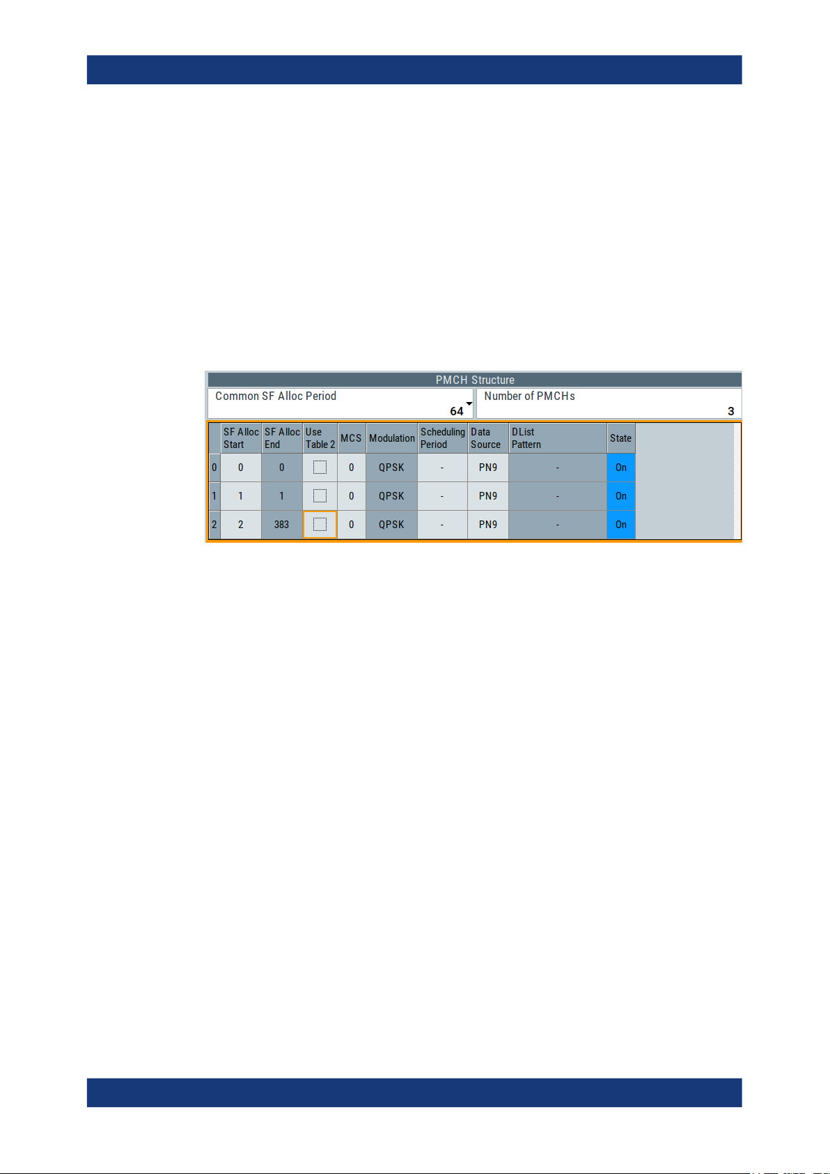
EUTRA/LTE configuration and settingsEUTRA/LTE/IoT
General DL settings / general TDD DL settings
Notification Pattern ← MBSFN-NotificationConfig Parameters ← Area Info (SIB
Type 13)
Sets the pattern for the notification bits sent on PDCCH DCI format 1c.
Remote command:
[:SOURce<hw>]:BB:EUTRa:DL:MBSFn:AI:MCCH:NPATtern on page 615
PMCH Structure
This section comprises settings for configuration of the PMCH structure, i.e. where to
find a PMCH carrying a certain MTCH. In the “real” system, these values are transmitted via the MCCH (MBSFNAreaConfiguration).
The parameters in this section correspond to the MBMS information elements
MBSFNAreaConfiguration and PMCH-InfoList, as defined in TS 36.331.
Common Subframe Allocation Period ← PMCH Structure
Defines the period during which resources corresponding with field commonSF-Alloc
are divided between the (P)MCHs that are configured for this MBSFN area.
The subframe allocation patterns, as defined by commonSF-Alloc, repeat continuously
during this period.
Remote command:
[:SOURce<hw>]:BB:EUTRa:DL:MBSFn:MTCH:CSAP on page 618
PMCH-InfoList Parameters ← PMCH Structure
Comprises the parameters of the PMCH-InfoList.
Number of PMCHs ← PMCH-InfoList Parameters ← PMCH Structure
Defines the number of PMCHs in this MBSFN area.
Remote command:
[:SOURce<hw>]:BB:EUTRa:DL:MBSFn:MTCH:NPMChs on page 618
SF Alloc Start/SF Alloc End ← PMCH-InfoList Parameters ← PMCH Structure
Defines the first/last subframe allocated to this (P)MCH within a period identified by
field commonSF-Alloc.
The subframes allocated to (P)MCH corresponding with the nth entry in pmch-InfoList
are the subsequent subframes starting from either the subframe identified by "SF Alloc
End" of the (–1)th listed (P)MCH or, for n=1, the first subframe, through the subframe
identified by "SF Alloc End" of the nth listed (P)MCH. Value 0 corresponds with the first
subframe defined by field commonSF-Alloc.
90User Manual 1178.8194.02 ─ 09

EUTRA/LTE configuration and settingsEUTRA/LTE/IoT
General DL settings / general TDD DL settings
Note: Configuring the MCHs ("SF Allocation Start" values) from bottom to top.
Although the 3GPP specification defines the "SF Alloc End" parameter as the only one
required, in this implementation it is mandatory to define the "SF Alloc Start" instead.
The implemented algorithm uses the selected "SF Alloc Start" and calculates automatically the "SF Alloc End" of the corresponding MCH. The algorithm applies the internal
rule, that there is no gap between two consequent MCHs.
It is therefore recommended to configure the MCHs, i.e. define the "SF Alloc Start" values, from bottom to the top. This workaround prevents the configuration of overlapping
MCHs.
Remote command:
[:SOURce<hw>]:BB:EUTRa:DL:MBSFn:PMCH<ch0>:SASTart on page 621
[:SOURce<hw>]:BB:EUTRa:DL:MBSFn:PMCH<ch0>:SAENd on page 621
Use Table 2 ← PMCH-InfoList Parameters ← PMCH Structure
(requires option R&S SMBVB-K113)
Defines which of the two tables defined in TS 36.213 is used to specify the used modu-
lation and coding scheme (see MCS and Modulation):
●
"Use Table 2 > Off": Table 7.1.7.1-1 is used
●
"Use Table 2 > On": Table 7.1.7.1-1A is used.
Example:
For "MCS = 5" and "Use Table 2 > Off", the used modulation is "Modulation > QPSK".
If "Use Table 2 > On", the used modulation changes to "Modulation > 16QAM".
Remote command:
[:SOURce<hw>]:BB:EUTRa:DL:MBSFn:PMCH<ch0>:MCSTwo on page 619
MCS ← PMCH-InfoList Parameters ← PMCH Structure
Defines the value for parameter according to TS 36.213 Table 7.1.7.1-1 or Table
7.1.7.1-1A, which defines the Modulation and Coding Scheme (MCS) applicable for the
subframes of this (P)MCH as indicated by the field commonSF-Alloc. The MCS does
however neither apply to the subframes that may carry MCCH, i.e. the subframes indicated by the field sf-AllocInfo within System Information Block Type 13, nor for the first
subframe of each MCH scheduling period (which may contain the MCH scheduling
information provided by the MAC).
To select which one of the two tables Table 7.1.7.1-1 or Table 7.1.7.1-1A is used, use
the parameter Use Table 2. Using Table 7.1.7.1-1A requires option R&S SMBVB-K113.
Remote command:
[:SOURce<hw>]:BB:EUTRa:DL:MBSFn:PMCH<ch0>:MCS on page 620
Modulation ← PMCH-InfoList Parameters ← PMCH Structure
Indicates the used modulation, as defined with:
●
Use Table 2
●
MCS
Remote command:
[:SOURce<hw>]:BB:EUTRa:DL:MBSFn:PMCH<ch0>:MOD? on page 620
91User Manual 1178.8194.02 ─ 09

EUTRA/LTE configuration and settingsEUTRA/LTE/IoT
General DL settings / general TDD DL settings
MCH Scheduling Period ← PMCH-InfoList Parameters ← PMCH Structure
Defines the MCH scheduling period, i.e. the periodicity used for providing MCH scheduling information at lower layers (MAC) applicable for an MCH.
Note: The first subframe of the scheduling period may contain the MAC control element and therefore uses MCS of MCCH (however, the data source from PMCH is still
used).
Remote command:
[:SOURce<hw>]:BB:EUTRa:DL:MBSFn:PMCH<ch0>:SPERiod on page 620
Data Source ← PMCH-InfoList Parameters ← PMCH Structure
Sets the data source for this PMCH/MTCH.
Remote command:
[:SOURce<hw>]:BB:EUTRa:DL:MBSFn:PMCH<ch0>:DATA on page 619
[:SOURce<hw>]:BB:EUTRa:DL:MBSFn:PMCH<ch0>:DLISt on page 619
[:SOURce<hw>]:BB:EUTRa:DL:MBSFn:PMCH<ch0>:PATTern on page 619
State ← PMCH-InfoList Parameters ← PMCH Structure
Enables/disables the selected PMCH/MTCH.
Remote command:
[:SOURce<hw>]:BB:EUTRa:DL:MBSFn:PMCH<ch0>:STATe on page 618
4.2.4 Physical settings
Access:
1. Select "General > Link Direction > Downlink (OFDMA)".
2. Select "General DL Settings > Physical".
In this dialog, the channel bandwidth respectively the number of resource blocks
per slot is selected. The other parameters are fixed and read-only.
92User Manual 1178.8194.02 ─ 09

EUTRA/LTE configuration and settingsEUTRA/LTE/IoT
General DL settings / general TDD DL settings
Channel Bandwidth.......................................................................................................93
Number of Resource Blocks Per Slot............................................................................93
FFT Size........................................................................................................................94
Number of eMTC Narrorbands......................................................................................94
Number of eMTC Widebands........................................................................................94
Wideband Config...........................................................................................................95
Physical Resource Block Bandwidth.............................................................................95
Occupied Bandwidth..................................................................................................... 95
Sampling Rate...............................................................................................................95
Number Of Occupied Subcarriers.................................................................................95
Number Of Left/Right Guard Subcarriers......................................................................95
Channel Bandwidth
Sets the channel bandwidth of the EUTRA/LTE system.
The 3GPP specification defines bandwidth agonistic layer 1 where the channel band-
width is determined by specifying the desired number of resource blocks. However, the
current EUTRA standardization focuses on six bandwidths.
●
"1.4 MHz, 3 MHz, 5 MHz, 10 MHz, 15 MHz, 20 MHz"
Select a predefined channel bandwidth.
The parameter "Number of Resource Blocks Per Slot" is internally calculated for
the selected "Channel Bandwidth" and "Physical Resource Block Bandwidth".
The sampling rate, occupied bandwidth and FFT size are therefore determined by
the parameter "Number of Resource Blocks Per Slot". If necessary, adjust the "FFT
Size".
See also Table 2-1 for an overview of the cross-reference between the parameters.
If "Mode > eMTC/NB-IoT or LTE/eMTC/NB-IoT" is selected, the "1.4 MHz" bandwidth is supported by LTE and eMTC; the NB-IoT-specific settings are not available
for configuration.
●
"200 kHz"
Option: R&S SMBVB-K115
This channel bandwidth is dedicated to NB-IoT. It is available, if "Mode >
eMTC/NB-IoT or LTE/eMTC/NB-IoT" is selected.
If channel bandwidth of 200 kHz is used, the LTE or eMTC-specific settings are not
available for configuration. Available is only one NB-IoT carrier which works in
standalone mode (Mode = "Standalone").
●
"User"
Option: R&S SMBVB-K55
Provided for backward compatibility with previous version of this software, this
parameter allows you to select a user-defined bandwidth as number of resource
blocks.
Remote command:
[:SOURce<hw>]:BB:EUTRa:DL:BW on page 582
Number of Resource Blocks Per Slot
Indicates the number of used resource blocks for the selected "Channel Bandwidth".
93User Manual 1178.8194.02 ─ 09

EUTRA/LTE configuration and settingsEUTRA/LTE/IoT
General DL settings / general TDD DL settings
"Channel Bandwidth" "Number of Resource Blocks Per Slot (UL)"
"1.4 MHz, 3 MHz, 5 MHz, 10 MHz, 15 MHz, 20
MHz"
"User" "Channel Bandwidth" depends on the "Number of
Read-only value, set automatically as function of the
"Channel Bandwidth" and "Physical Resource Block
Bandwidth"
Resource Blocks Per Slot" and "Physical Resource
Blocks Bandwidth"
The sampling rate and the occupied bandwidth are determined by the parameter
"Number of Resource Blocks Per Slot". If necessary, adjust the value of "FFT Size".
See also Table 2-1.
Remote command:
[:SOURce<hw>]:BB:EUTRa:DL:NORB on page 582
FFT Size
Sets the FFT (Fast Fourier Transformation) size.
You can change the FFT size for all bandwidth definitions if the following conditions are
met:
●
For a specific bandwidth, all FFT sizes are applicable as long as the size is greater
than the number of occupied subcarriers.
By default, the smallest available FFT size is selected.
●
To decrease the number of unused guard subcarriers and the resulting sampling
rate, for channel bandwidth of 15 MHz an FFT size of 1536 is provided, too.
Remote command:
[:SOURce<hw>]:BB:EUTRa:DL:FFT on page 583
Number of eMTC Narrorbands
Option: R&S SMBVB-K115
This parameter is dedicated to eMTC and available if "Mode > eMTC/NB-IoT or LTE/
eMTC/NB-IoT" is selected.
It indicates the number of eMTC narrowbands N
DL
available within the selected
RB
channel bandwidth.
The value is calculated as follows:
"Number of Narrorbands" = "Number of Resource Blocks" / 6
For more information, see "Narrowbands" on page 331.
Remote command:
[:SOURce<hw>]:BB:EUTRa:DL:EMTC:NNBands? on page 823
Number of eMTC Widebands
Option: R&S SMBVB-K143
This parameter is dedicated to eMTC and available if "Mode > eMTC/NB-IoT or LTE/
eMTC/NB-IoT" and Wideband Config > "5 MHz/20 MHz" is selected.
It indicates the number of eMTC widebands NWB available within the selected channel
bandwidth.
The value is calculated as follows:
94User Manual 1178.8194.02 ─ 09

EUTRA/LTE configuration and settingsEUTRA/LTE/IoT
General DL settings / general TDD DL settings
"Number of Widebands" = "Channel Bandwidth" / Wideband Config
For more information, see "Widebands" on page 332.
Remote command:
[:SOURce<hw>]:BB:EUTRa:DL:EMTC:NWBands? on page 824
Wideband Config
Option: R&S SMBVB-K143
This parameter is dedicated to eMTC and available if "Mode > eMTC/NB-IoT or LTE/
eMTC/NB-IoT" is selected.
If enabled, the available channel bandwidth is split into eMTC widebands with the
selected bandwidth. The resulting number of widebands is indicated by the parameter
Number of eMTC Widebands.
For more information, see "Widebands" on page 332.
Remote command:
[:SOURce<hw>]:BB:EUTRa:DL:EMTC:WBCFg on page 823
Physical Resource Block Bandwidth
Displays the bandwidth of one physical resource block. The value is fixed to 12 x 15
kHz.
Remote command:
n.a.
Occupied Bandwidth
Displays the occupied bandwidth, calculated from the parameter "Number of Resource
Blocks Per Slot".
Remote command:
[:SOURce<hw>]:BB:EUTRa:DL:OCCBandwidth? on page 583
Sampling Rate
Displays the sampling rate, calculated from the parameter "Number of Resource
Blocks Per Slot".
Remote command:
[:SOURce<hw>]:BB:EUTRa:DL:SRATe? on page 583
Number Of Occupied Subcarriers
Displays the number of occupied subcarriers, calculated from the parameter "Number
of Resource Blocks Per Slot".
Remote command:
[:SOURce<hw>]:BB:EUTRa:DL:OCCSubcarriers? on page 584
Number Of Left/Right Guard Subcarriers
Displays the number of left/right guard subcarriers, calculated form the parameter
"Number of Resource Blocks Per Slot".
Remote command:
[:SOURce<hw>]:BB:EUTRa:DL:LGS? on page 584
[:SOURce<hw>]:BB:EUTRa:DL:RGS? on page 584
95User Manual 1178.8194.02 ─ 09

4.2.5 Cell-specific settings
Access:
1. Select "General > Link Direction > Downlink (OFDMA)".
2. Select "General DL Settings > Cell".
EUTRA/LTE configuration and settingsEUTRA/LTE/IoT
General DL settings / general TDD DL settings
The "Cell-Specific Settings" section comprises the physical layer cell identity settings and the DL power control settings.
The TDD settings are available only, if the TDD is selected as a duplexing mode.
The TDD frame is configured by adjusting the UL/DL configuration and the special
subframe configuration.
Cell ID........................................................................................................................... 96
Physical Cell ID Group..................................................................................................97
Physical Layer ID.......................................................................................................... 97
Cyclic Prefix (General DL Settings)...............................................................................97
UL/DL Cyclic Prefix....................................................................................................... 97
PDSCH P_B..................................................................................................................98
PDSCH/PDCCH/PBCH Ratio rho_B/rho_A.................................................................. 98
PHICH Duration............................................................................................................ 98
PHICH N_g................................................................................................................... 98
RA_RNTI.......................................................................................................................99
Cell ID
Sets the cell identity.
There are 504 unique physical layer cell identities (Cell ID), grouped into 168 unique
physical cell identity groups that contain three unique identities each. The Cell ID is
calculated as following:
Cell ID = 3*Physical Cell ID Group + Physical Layer ID
96User Manual 1178.8194.02 ─ 09

EUTRA/LTE configuration and settingsEUTRA/LTE/IoT
General DL settings / general TDD DL settings
There is a cross-reference between the values of these three parameters and changing of one of them results in adjustment in the values of the others.
The Cell ID determinates:
●
The downlink reference signal pseudo-random sequence
●
The frequency shifts of the reference signal
●
The S-SYNC sequence
●
The cyclic shifts for PCFICH, PHICH and PDCCH mapping
●
The pseudo-random sequence used for scrambling
Remote command:
[:SOURce<hw>]:BB:EUTRa:DL[:PLCI]:CID on page 585
Physical Cell ID Group
Sets the physical cell identity group.
To configure these identities within a cell ID group, set the parameter Physical Layer
ID.
Remote command:
[:SOURce<hw>]:BB:EUTRa:DL[:PLCI]:CIDGroup on page 585
Physical Layer ID
Sets the identity of the physical layer within the selected physical cell identity group,
set with parameter Physical Cell ID Group .
The physical layer ID determinates the Zadoff-Chu orthogonal sequence carried by the
PSS (P-SYNC) and used for cell search.
Remote command:
[:SOURce<hw>]:BB:EUTRa:DL[:PLCI]:PLID on page 585
Cyclic Prefix (General DL Settings)
Sets the cyclic prefix length for all subframes.
The number of the OFDM symbols is set automatically.
"Normal"
"Extended"
"User Defined"
Remote command:
[:SOURce<hw>]:BB:EUTRa:DL:CPC on page 586
Normal cyclic prefix, i.e. the DL slot contains seven OFDM symbols.
Extended cyclic prefix, i.e. the DL slot contains six OFDM symbols.
The extended cyclic prefix is defined to cover large cell scenarios with
higher delay spread and MBMS transmission.
NB-IoT allocations cannot be activated.
To set the cyclic prefix length per subframe, use the parameter "DL
Frame Configuration" > "Cyclic Prefix".
UL/DL Cyclic Prefix
In "Duplexing > TDD", determines the cyclic prefix for the appropriate opposite direction.
Remote command:
[:SOURce<hw>]:BB:EUTRa:UL:DLCPc on page 594
[:SOURce<hw>]:BB:EUTRa:DL:ULCPc on page 586
97User Manual 1178.8194.02 ─ 09

EUTRA/LTE configuration and settingsEUTRA/LTE/IoT
General DL settings / general TDD DL settings
PDSCH P_B
Defines the cell-specific ratio rho_B/rho_A according to TS 36.213 (Table 5.2-1).
The following table gives an overview of the resulting values of the parameter "PDSCH
Ratio rho_B/rho_A" as function of the values for the parameter [PDSCH P_B] and the
number of configured antennas.
PDSCH P_B 1 Tx antenna 2 or 4 Tx antennas
0 0.000 dB 0.969 dB
1 -0.969 dB 0.000 dB
2 -2.218 dB -1.249 dB
3 -3.979 dB - 3.010 dB
Remote command:
[:SOURce<hw>]:BB:EUTRa:DL:PDSCh:PB on page 586
PDSCH/PDCCH/PBCH Ratio rho_B/rho_A
Displays or sets the transmit energy ratio among the resource elements allocated for
PDSCH/PDCCH/PBCH in the OFDM symbols containing reference signal (P_B) and
such not containing one (P_A).
The PDSCH value is calculated form the parameter PDSCH P_B. It also depends on
the number of configured antennas.
Remote command:
[:SOURce<hw>]:BB:EUTRa:DL:PDSCh:RATBa on page 587
[:SOURce<hw>]:BB:EUTRa:DL:PDCCh:RATBa on page 587
[:SOURce<hw>]:BB:EUTRa:DL:PBCH:RATBa on page 587
PHICH Duration
Sets the PHICH duration, i.e. the allocation of the PHICH resource element groups
over the OFDM symbols.
The value selected puts the lower limit of the size of the PCFICH settings that is signaled by the PCFICH.
If Activate Carrier Aggregation > "On", you can define the PHICH duration per component carrier.
"Normal"
All resources element groups of PHICH (see Number of PHICH
Groups) are allocated on the first OFDM symbol (OFDM Symbol 0).
"Extended"
The resources element groups of PHICH are distributed over three
OFDM symbols for a normal subframe or over two symbols within a
special one.
Remote command:
[:SOURce<hw>]:BB:EUTRa:DL:CA:CELL<ch0>:PHICh:DURation on page 627
PHICH N_g
Sets the parameter N_g according to TS 36.211, section 6.9.
If Activate Carrier Aggregation > "On", you can define the PHICH duration per compo-
nent carrier.
98User Manual 1178.8194.02 ─ 09

EUTRA/LTE configuration and settingsEUTRA/LTE/IoT
General DL settings / general TDD DL settings
"1/6, 1/2, 1, 2"
The used Number of PHICH Groups for the different subframes is calculated according to the following formula:
In FDD mode, the calculated value corresponds directly to the parameter "Number of PHICH Groups".
In TDD mode, the number of PHICH groups is calculated as the product of the N
group
value multiplied with a coefficient selected from
PHICH
the following table.
UL/DL Subframe number
Configuration
0 2 1 - - - 2 1 - - -
1 0 1 - - 1 0 1 - - 1
2 0 0 - 1 0 0 0 - 1 0
3 1 0 - - - 0 0 0 1 1
4 0 0 - - 0 0 0 0 1 1
5 0 0 - 0 0 0 0 0 1 0
0 1 2 3 4 5 6 7 8 9
6 1 1 - - - 1 1 - - 1
The parameter Number of PHICH Groups is read-only.
"Custom"
(for Activate Carrier Aggregation > "Off")
The parameter Number of PHICH Groups is configurable.
Remote command:
[:SOURce<hw>]:BB:EUTRa:DL:CA:CELL<ch0>:PHICh:NGParameter
on page 627
RA_RNTI
Sets the random-access response identity RA-RNTI for the users.
The value selected here determined the value of the parameter UE_ID/n_RNTI in case
a RA_RNTI "User" is selected.
See UE_ID/n_RNTI.
Remote command:
[:SOURce<hw>]:BB:EUTRa:DL:CSETtings:RARNti on page 585
99User Manual 1178.8194.02 ─ 09

4.2.6 TDD frame structure settings
Access:
► Select "EUTRA/LTE > Duplexing > TDD".
The TDD frame is configured by adjusting the UL/DL configuration and the special
subframe configuration (see also Chapter 2.2.1.1, "OFDMA parameterization",
on page 21).
TDD UL/DL Configuration
Sets the UL/DL configuration number and defines which subframe is used for downlink
respectively uplink, and where the special subframes are located.
Remote command:
[:SOURce<hw>]:BB:EUTRa:TDD:UDConf on page 576
EUTRA/LTE configuration and settingsEUTRA/LTE/IoT
General DL settings / general TDD DL settings
TDD Special Subframe Config
Sets the special subframe configuration number and together with the parameter
"Cyclic Prefix" defines the lengths of the DwPTS, the guard period (GP) and the
UpPTS.
The DwPTS length selected with this parameter determines the maximum number of
the OFDM symbols available for PDSCH in the special subframe.
The UpPTS length selected with this parameter determines the maximum number of
the SC-FDMA symbols available for SRS in the special subframe.
Remote command:
[:SOURce<hw>]:BB:EUTRa:TDD:SPSConf on page 576
Number of UpPTS Symbols
Option: R&S SMBVB-K119 (if "Mode = LTE")
Option: R&S SMBVB-K143 (if "Mode = eMTC/NB-IoT")
For TDD Special Subframe Config = 10, sets the number of UpPTS symbols.
In all other configurations, the number of UpPTS symbols is set automatically depend-
ing on:
●
"TDD UL/DL Configuration" on page 100
●
"TDD Special Subframe Config" on page 100.
Remote command:
[:SOURce<hw>]:BB:EUTRa:TDD:UPTS on page 577
100User Manual 1178.8194.02 ─ 09
 Loading...