


R&S®SMB100B
RF Signal Generator
User Manual
(;ÜU;2)
1178371102
User Manual
Version 04

This document describes the R&S®SMB100B, stock no. 1422.1000.02 and its options:
●
R&S®SMBB-B1/-B1H
●
R&S®SMBB-B3
●
R&S®SMBB-B5
●
R&S®SMBB-B32
●
R&S®SMBB-B86
●
R&S®SMBB-B101/-B103/-B106
●
R&S®SMBB-K22/-K23/-K24/-K27
●
R&S®SMBB-K31
●
R&S®SMBB-K704
●
R&S®SMBB-K720
This manual describes firmware version FW 4.60.112.xx and later of the R&S®SMB100B.
© 2019 Rohde & Schwarz GmbH & Co. KG
Mühldorfstr. 15, 81671 München, Germany
Phone: +49 89 41 29 - 0
Fax: +49 89 41 29 12 164
Email: info@rohde-schwarz.com
Internet: www.rohde-schwarz.com
Subject to change – Data without tolerance limits is not binding.
R&S® is a registered trademark of Rohde & Schwarz GmbH & Co. KG.
Trade names are trademarks of the owners.
1178.3711.02 | Version 04 | R&S®SMB100B
Throughout this manual, products from Rohde & Schwarz are indicated without the ® symbol , e.g. R&S®SMB100B is indicated as
R&S SMB100B, R&S®VISA as R&S VISA. Linux® is abbreviated as Linux.

R&S®SMB100B
1 Preface.................................................................................................. 15
1.1 Key Features................................................................................................................15
1.2 About this Manual....................................................................................................... 15
1.3 Documentation Overview........................................................................................... 16
1.3.1 Getting Started Manual................................................................................................. 17
1.3.2 User Manuals and Help.................................................................................................17
1.3.3 Service Manual............................................................................................................. 17
1.3.4 Instrument Security Procedures....................................................................................17
1.3.5 Basic Safety Instructions...............................................................................................17
1.3.6 Data Sheets and Brochures.......................................................................................... 17
1.3.7 Release Notes and Open Source Acknowledgment (OSA).......................................... 18
Contents
Contents
1.3.8 Application Notes, Application Cards, White Papers, etc..............................................18
2 Safety Information................................................................................19
3 Getting Started..................................................................................... 20
3.1 Preparing for Use........................................................................................................ 20
3.1.1 Putting into Operation................................................................................................... 20
3.1.1.1 EMI Suppression...........................................................................................................21
3.1.1.2 Unpacking and Checking the Instrument...................................................................... 21
3.1.1.3 Accessory List............................................................................................................... 22
3.1.1.4 Placing or Mounting the Instrument.............................................................................. 22
3.1.1.5 Connecting AC Power...................................................................................................23
3.1.1.6 Turning the Instrument On and Off................................................................................24
3.1.1.7 Functional Check.......................................................................................................... 25
3.1.1.8 Checking the Supplied Options and Licenses...............................................................26
3.1.2 Connecting USB Devices..............................................................................................26
3.1.3 Setting Up a Network (LAN) Connection.......................................................................27
3.1.3.1 Connecting the Instrument to the Network....................................................................27
3.1.3.2 Using Computer Names (Hostnames).......................................................................... 28
3.1.3.3 Assigning the IP Address.............................................................................................. 29
3.2 Instrument Tour...........................................................................................................30
3.2.1 Front Panel Tour............................................................................................................31
3User Manual 1178.3711.02 ─ 04

R&S®SMB100B
3.2.1.1 Touchscreen..................................................................................................................31
3.2.1.2 Utility Keys.................................................................................................................... 32
3.2.1.3 On/Standby................................................................................................................... 33
3.2.1.4 Function Keys............................................................................................................... 33
3.2.1.5 Keypad.......................................................................................................................... 33
3.2.1.6 Navigation Controls.......................................................................................................34
3.2.1.7 Display Keys................................................................................................................. 35
3.2.1.8 USB Connector............................................................................................................. 35
3.2.1.9 RF 50 Ω.........................................................................................................................36
3.2.2 Rear Panel Tour............................................................................................................ 36
3.2.2.1 Connectors....................................................................................................................37
3.3 Trying Out the Instrument.......................................................................................... 38
3.3.1 Generating an Unmodulated Carrier............................................................................. 39
Contents
3.3.2 Generating an RF Frequency Sweep Signal.................................................................41
3.3.3 Saving and Recalling Settings...................................................................................... 43
3.4 Instrument Control......................................................................................................46
3.4.1 Possible Ways to Operate the Instrument.....................................................................47
3.4.2 Means of Manual Interaction.........................................................................................47
3.4.3 Understanding the Display Information......................................................................... 48
3.4.3.1 Status Bar..................................................................................................................... 49
3.4.3.2 Tile Diagram..................................................................................................................49
3.4.3.3 Taskbar..........................................................................................................................49
3.4.3.4 Additional Display Characteristics.................................................................................50
3.4.4 Accessing the Functionality...........................................................................................51
3.4.5 Entering Data................................................................................................................ 52
3.4.5.1 Entering Numeric Parameters.......................................................................................53
3.4.5.2 Entering Alphanumeric Parameters.............................................................................. 53
3.4.5.3 Undo and Redo Actions................................................................................................ 53
3.4.6 Getting Information and Help........................................................................................ 53
3.4.7 Remote Control............................................................................................................. 55
3.4.8 Remote Operation over VNC........................................................................................ 56
4 RF Signal Configuration......................................................................57
4.1 Activating RF Signal Output...................................................................................... 58
4User Manual 1178.3711.02 ─ 04

R&S®SMB100B
4.2 How to Set the Frequency and Level........................................................................ 58
4.3 RF Frequency Settings............................................................................................... 60
4.4 RF Level Settings........................................................................................................ 62
4.5 RF Phase Settings.......................................................................................................66
5 Analog Modulations.............................................................................68
5.1 Required Options........................................................................................................ 68
5.2 Modulation Types and Signal Sources......................................................................68
5.3 Activating Analog Modulations................................................................................. 70
5.4 Modulation Settings....................................................................................................70
5.4.1 Pulse Modulation...........................................................................................................71
5.4.2 FM, PhiM and AM Modulation Settings.........................................................................72
5.4.3 Stereo Modulation......................................................................................................... 78
Contents
5.4.3.1 General Settings........................................................................................................... 79
5.4.3.2 Pilot Tone...................................................................................................................... 81
5.4.3.3 ARI................................................................................................................................ 82
5.4.3.4 RDS...............................................................................................................................84
5.4.4 Pulse Generator............................................................................................................ 86
5.4.4.1 Pulse Generator > General Settings............................................................................. 87
5.4.4.2 Pulse Generator > Pulse Train Settings........................................................................89
5.4.4.3 Import/Export List Files................................................................................................. 92
5.4.5 Pulse Graph.................................................................................................................. 95
5.4.6 Pulse External / Trigger Settings...................................................................................96
5.4.7 FM, PhiM and AM Modulation Sources.........................................................................97
5.4.7.1 Source > LF Generator Settings................................................................................... 97
5.4.7.2 Source > External Settings..........................................................................................101
5.4.7.3 Source > Noise Generator Settings............................................................................ 102
5.4.8 LF Signal Output Settings........................................................................................... 103
5.4.9 Overview..................................................................................................................... 105
5.5 How to Generate an Amplitude Modulated Signal................................................. 107
5.6 How to Generate a Pulse Modulated Signal........................................................... 107
5.7 How to Generate a Pulse Train Modulated Signal..................................................108
6 List and Sweep Mode.........................................................................110
6.1 Signal Generation and Triggering in the Sweep and List Modes......................... 112
5User Manual 1178.3711.02 ─ 04

R&S®SMB100B
6.2 About Sweep Mode................................................................................................... 119
6.2.1 Correlating Parameters in Sweep Mode..................................................................... 120
6.2.2 Sweep Signal Shapes................................................................................................. 122
6.3 About List Mode........................................................................................................ 123
6.4 Significant Parameters and Functions....................................................................124
6.5 Sweep Mode Settings............................................................................................... 125
6.5.1 General Sweep Settings............................................................................................. 126
6.5.2 Frequency Range Settings..........................................................................................131
6.5.3 Level Range Settings.................................................................................................. 132
6.6 List Mode Settings.................................................................................................... 134
6.6.1 General Settings......................................................................................................... 135
6.6.2 List Mode Data Settings.............................................................................................. 137
6.6.3 Import/Export Settings.................................................................................................138
Contents
6.7 List Editor.................................................................................................................. 141
6.8 How to Generate a Signal in List or Sweep Mode..................................................144
7 Improving Level Performance...........................................................147
7.1 Attenuator.................................................................................................................. 147
7.1.1 Attenuator Settings......................................................................................................148
7.1.2 Reverse Power Protection.......................................................................................... 149
7.2 Automatic Level Control (ALC)................................................................................149
7.2.1 ALC Settings............................................................................................................... 151
7.3 User Correction......................................................................................................... 152
7.3.1 User Correction Settings............................................................................................. 155
7.3.2 List Editor.................................................................................................................... 156
7.3.3 Fill with Sensor............................................................................................................160
7.3.4 Import/Export List Files............................................................................................... 161
7.4 Using Power Sensors............................................................................................... 164
7.4.1 Connecting R&S NRP Power Sensors to the R&S SMB100B.................................... 164
7.4.2 NRP Sensor Mapping................................................................................................. 165
7.4.3 NRP Power Viewer......................................................................................................167
7.4.3.1 About...........................................................................................................................167
7.4.3.2 NRP Power Viewer Settings........................................................................................169
7.5 How to Calibrate the Power Level with an R&S NRP Power Sensor....................174
6User Manual 1178.3711.02 ─ 04

R&S®SMB100B
8 Reference Oscillator.......................................................................... 178
8.1 Required Options...................................................................................................... 178
8.2 Using the Reference Frequency for Instruments Synchronization......................178
8.3 Reference Frequency Settings................................................................................ 181
8.4 Reference Output Settings.......................................................................................184
8.5 Adjustment Settings................................................................................................. 185
9 File and Data Management................................................................187
9.1 About the File System.............................................................................................. 187
9.2 Restoring the (Default) Instrument Configuration................................................. 190
9.2.1 Preset, Set to Default and Factory Preset Settings.....................................................192
9.2.2 How to Identify Parameters Which Are Not in a Preset State..................................... 193
9.2.3 How to Recall User Settings Automatically after Preset............................................. 193
Contents
9.2.4 Reference....................................................................................................................194
9.3 Protecting Data..........................................................................................................195
9.4 Saving and Recalling Instrument Settings............................................................. 195
9.4.1 Save/Recall Settings................................................................................................... 196
9.4.2 How to Save and Recall Instrument Settings..............................................................199
9.5 Accessing Files with User Data............................................................................... 200
9.5.1 File Select Settings..................................................................................................... 200
9.6 Exporting Remote Command Lists......................................................................... 202
9.7 Loading, Importing and Exporting Lists................................................................. 203
9.8 Using the File Manager.............................................................................................203
9.8.1 File Manager Settings................................................................................................. 204
9.8.2 Map Network Share Settings...................................................................................... 205
9.8.3 How to Display All Saved Files................................................................................... 207
9.8.4 How to Map a Network Folder.....................................................................................207
9.9 How to Transfer Files from and to the Instrument.................................................210
9.9.1 Removing File System Protection............................................................................... 210
9.9.2 Accessing the File System of the R&S SMB100B Via ftp........................................... 212
9.9.3 Accessing the R&S SMB100B File System Via SMB (Samba)...................................213
9.9.4 Using a USB Storage Device for File Transfer............................................................215
9.9.5 Using a File Server for Test Files Exchange............................................................... 215
9.10 Creating Screenshots of Current Settings............................................................. 216
7User Manual 1178.3711.02 ─ 04

R&S®SMB100B
9.10.1 Hardcopy Settings.......................................................................................................216
9.10.2 How to Save a Hardcopy of the Display......................................................................220
10 General Instrument Functions..........................................................222
10.1 Customizing the User Interface............................................................................... 222
10.1.1 Display and Keyboard Settings................................................................................... 223
10.1.2 Display Update Settings..............................................................................................224
10.1.3 Defining the RF Signal State On Power On ............................................................... 225
10.1.4 How to Set the Initial Instrument Settings................................................................... 226
10.1.4.1 Setting the Keyboard Language..................................................................................226
10.1.4.2 Setting the Screen Saver............................................................................................ 226
10.2 Organizing Frequently Used Settings as Favorites............................................... 227
10.2.1 Using the User Menu for Fast Adjustments................................................................ 228
Contents
10.2.2 Define User Key Actions Settings............................................................................... 230
10.2.3 Assigning Actions to the [★ (User)] Key......................................................................231
10.3 Managing Licenses and License Keys....................................................................233
10.3.1 Manage License Keys Settings...................................................................................233
10.3.2 How to Move a Portable License................................................................................ 235
10.4 Using the Security Settings..................................................................................... 237
10.4.1 Protection Level Settings............................................................................................ 238
10.4.2 Setting Security Parameters....................................................................................... 239
10.4.2.1 Update Policy Security Settings.................................................................................. 239
10.4.2.2 Disk & Memory Security Settings................................................................................240
10.4.2.3 Manual Operation Security Settings............................................................................242
10.4.3 Configuring LAN Services........................................................................................... 245
10.4.4 Password Management.............................................................................................. 246
10.5 Undoing or Restoring Actions................................................................................. 249
10.6 Shutting Down and Rebooting the Instrument.......................................................250
11 Network Operation and Remote Control..........................................251
11.1 Overview of Remote Access Modes........................................................................251
11.2 Remote Control Interfaces and Protocols.............................................................. 253
11.2.1 LAN Interface.............................................................................................................. 254
11.2.1.1 VISA Resource Strings............................................................................................... 254
11.2.1.2 HiSLIP Protocol...........................................................................................................256
8User Manual 1178.3711.02 ─ 04

R&S®SMB100B
11.2.1.3 VXI-11 Protocol........................................................................................................... 256
11.2.1.4 Socket Communication............................................................................................... 256
11.2.2 USB Interface..............................................................................................................257
11.2.2.1 USB Resource String.................................................................................................. 257
11.2.3 GPIB Interface (IEC/IEEE Bus Interface)....................................................................258
11.2.4 LXI Browser Interface..................................................................................................258
11.3 Remote Control Programs and Libraries................................................................259
11.3.1 VISA Library................................................................................................................ 259
11.3.2 Possible Setups and Access Functions...................................................................... 260
11.4 Remote Access Settings.......................................................................................... 262
11.4.1 Network Settings......................................................................................................... 263
11.4.2 VISA Resource Strings............................................................................................... 266
11.4.3 GPIB Address Settings............................................................................................... 267
Contents
11.4.4 RS232 Settings........................................................................................................... 267
11.4.5 Instrument Emulations Settings.................................................................................. 268
11.4.6 Remote Connections Settings.....................................................................................269
11.4.6.1 Active Connections..................................................................................................... 269
11.4.6.2 Closed Connections.................................................................................................... 270
11.4.7 QR Code..................................................................................................................... 271
11.5 LXI Settings............................................................................................................... 272
11.5.1 LXI Status Settings......................................................................................................272
11.5.2 LXI Browser Settings...................................................................................................274
11.5.2.1 LAN Configuration.......................................................................................................275
11.6 How to Find the VISA Resource String...................................................................279
11.7 How to Change the GPIB Instrument Address.......................................................280
11.8 How to Set Up a Remote Control Connection........................................................280
11.8.1 Establishing a Remote Control Connection over the LXI Browser Interface...............281
11.8.2 Establishing a Remote Control Connection over LAN Using VXI-11 Protocol............ 281
11.8.3 Setting Up a Remote Control Connection over LAN Using Socket Communication...286
11.8.4 Setting Up a Remote Control Connection over GPIB................................................. 287
11.8.5 Setting Up a Remote Control Connection over USB...................................................288
11.9 Tracing SCPI Commands and Messages Exchanged via the LXI Web Browser
Interface..................................................................................................................... 289
11.10 How to Return to Manual Operation........................................................................289
9User Manual 1178.3711.02 ─ 04

R&S®SMB100B
11.11 Automating Tasks with Remote Command Scripts............................................... 290
11.11.1 Show SCPI Command................................................................................................ 293
11.11.2 Displaying an SCPI List...............................................................................................293
11.11.3 SCPI Recording Export Settings................................................................................. 294
11.12 How to Find Out the SCPI Command Corresponding to the Manual Operation via
Show SCPI Command...............................................................................................295
11.13 How to Find Out the SCPI Command Corresponding to the Manual Operation
Using the Online Help...............................................................................................296
11.14 How to Record / Create SCPI Lists..........................................................................296
11.15 How to Convert and Save SCPI Lists......................................................................299
11.16 How to Set Up Remote Operation via VNC.............................................................300
11.16.1 Setting Up a Remote Operation from a Desktop System............................................301
11.16.1.1 Using a Web Browser..................................................................................................301
Contents
11.16.1.2 Using a VNC Client Software...................................................................................... 301
11.16.2 Setting Up a Remote Operation from a Smart Device................................................ 303
11.16.2.1 Using a VNC App........................................................................................................ 304
11.16.2.2 Using a Web Browser with HTML5............................................................................. 305
11.16.2.3 Special Mode QR Code ............................................................................................. 305
11.17 References.................................................................................................................306
11.17.1 LXI Functionality..........................................................................................................306
11.17.2 Code Generator Templates.........................................................................................306
11.17.3 Remote Control States ...............................................................................................308
12 Remote Control Commands..............................................................310
12.1 Conventions used in SCPI Command Descriptions.............................................. 310
12.2 Programming Examples........................................................................................... 311
12.3 Common Commands................................................................................................ 311
12.4 Preset Commands.....................................................................................................316
12.5 MMEMory Subsystem............................................................................................... 317
12.5.1 File Naming Conventions............................................................................................ 318
12.5.2 Accessing Files in the Default or in a Specified Directory...........................................318
12.5.3 Programming Examples..............................................................................................320
12.5.4 Remote Control Commands........................................................................................322
12.6 CALibration Subsystem........................................................................................... 327
12.7 DIAGnostic Subsystem............................................................................................ 330
10User Manual 1178.3711.02 ─ 04

R&S®SMB100B
12.8 DISPlay Subsystem...................................................................................................332
12.9 FORMat Subsystem.................................................................................................. 337
12.10 HCOPy Subsystem....................................................................................................339
12.10.1 Hard Copy Settings..................................................................................................... 340
12.10.2 Automatic Naming.......................................................................................................341
12.11 KBOard Subsystem.................................................................................................. 344
12.12 OUTPut Subsystem...................................................................................................344
12.13 SENSe, READ, INITiate and SLISt Subsystems......................................................347
12.14 SOURce Subsystem..................................................................................................359
12.14.1 Analog Modulation Subsystems..................................................................................360
12.14.1.1 SOURce:MODulation Subsystem............................................................................... 360
12.14.1.2 SOURce:AM Subsystem.............................................................................................361
12.14.1.3 SOURce:FM Subsystem............................................................................................. 366
Contents
12.14.1.4 SOURce:PM Subsystem.............................................................................................370
12.14.1.5 SOURce:PULM Subsystem........................................................................................ 375
12.14.1.6 SOURce:STEReo Subsystem.....................................................................................386
12.14.2 SOURce:CORRection Subsystem.............................................................................. 393
12.14.2.1 Correction Settings......................................................................................................396
12.14.2.2 Correction Data Exchange.......................................................................................... 399
12.14.3 SOURce:FREQuency Subsystem...............................................................................401
12.14.4 SOURce:INPut Subsystem......................................................................................... 407
12.14.5 SOURce:LFOutput Subsystem................................................................................... 408
12.14.5.1 LF Generator Settings.................................................................................................410
12.14.5.2 LF Sweep Settings...................................................................................................... 418
12.14.6 SOURce:LIST Subsystem...........................................................................................421
12.14.6.1 List Mode Settings.......................................................................................................424
12.14.6.2 List Mode File Operation............................................................................................. 429
12.14.6.3 List Mode Data Exchange........................................................................................... 432
12.14.7 SOURce:NOISe Subsystem....................................................................................... 434
12.14.7.1 Noise Generator..........................................................................................................435
12.14.8 SOURce:PGEN Subsystem........................................................................................ 436
12.14.9 SOURce:PHASe Subsystem...................................................................................... 438
12.14.10 SOURce:POWer Subsystem.......................................................................................438
11User Manual 1178.3711.02 ─ 04

R&S®SMB100B
12.14.11 SOURce:ROSCillator Subsystem............................................................................... 447
12.14.12 SOURce:SWEep Subsystem...................................................................................... 452
12.15 SYSTem Subsystem..................................................................................................460
12.16 STATus Subsystem................................................................................................... 485
12.17 TEST Subsystem.......................................................................................................488
12.18 TRIGger Subsystem..................................................................................................489
12.19 UNIT Subsystem........................................................................................................492
12.20 Direct Commands for the Stereo/RDS Coder Option R&S SMBB-B5.................. 493
12.20.1 Programming Examples..............................................................................................493
12.20.2 Remote-Control Commands....................................................................................... 496
13 Maintenance....................................................................................... 515
13.1 Cleaning..................................................................................................................... 515
Contents
13.2 Storing and Packing................................................................................................. 516
13.3 Performing Maintenance Tasks............................................................................... 517
13.3.1 Date and Time Settings...............................................................................................517
13.3.2 Check Front Panel...................................................................................................... 519
13.3.2.1 Check Front Panel Settings........................................................................................ 520
13.3.2.2 How to Test the Front Panel........................................................................................520
13.3.3 Internal Adjustment Settings....................................................................................... 523
13.3.4 FPGA/uC Update Settings.......................................................................................... 524
13.3.5 Requesting Instrument Configuration and Specifications........................................... 526
13.3.5.1 Hardware Configuration Settings................................................................................ 526
13.3.5.2 Versions/Options Settings...........................................................................................527
13.3.5.3 Requesting the Data Sheet......................................................................................... 529
14 Troubleshooting and Error Messages..............................................530
14.1 Error Messages......................................................................................................... 530
14.1.1 Volatile Messages....................................................................................................... 530
14.1.2 Permanent Messages................................................................................................. 530
14.2 SCPI-Error Messages................................................................................................531
14.3 Device-Specific Error Messages..............................................................................531
14.4 Querying Error Messages........................................................................................ 532
14.5 Resolving Network Connection Failures................................................................ 534
14.6 Collecting Information for Technical Support........................................................ 535
12User Manual 1178.3711.02 ─ 04

R&S®SMB100B
A Reference Information for Remote Control..................................... 538
A.1 Additional Basics on Remote Control.....................................................................538
A.1.1 Messages....................................................................................................................538
A.1.2 LAN Interface Messages.............................................................................................539
A.1.3 SCPI Command Structure...........................................................................................539
A.1.3.1 Syntax for Common Commands................................................................................. 540
A.1.3.2 Syntax for Device-Specific Commands.......................................................................540
A.1.3.3 SCPI Parameters........................................................................................................ 542
A.1.3.4 Overview of Syntax Elements..................................................................................... 544
A.1.3.5 Structure of a Command Line..................................................................................... 546
A.1.3.6 Responses to Queries.................................................................................................546
Contents
Annex.................................................................................................. 538
A.1.4 Command Sequence and Synchronization.................................................................547
A.1.4.1 Preventing Overlapping Execution..............................................................................547
A.1.4.2 Examples to Command Sequence and Synchronization............................................ 549
A.1.5 Status Reporting System............................................................................................ 550
A.1.5.1 Hierarchy of the Status Registers............................................................................... 551
A.1.5.2 Structure of a SCPI Status Register............................................................................552
A.1.5.3 Status Byte (STB) and Service Request Enable Register (SRE)................................554
A.1.5.4 Event Status Register (ESR) and Event Status Enable Register (ESE)..................... 555
A.1.5.5 Questionable Status Register (STATus:QUEStionable)..............................................556
A.1.5.6 Operation Status Register (STATus:OPERation)........................................................556
A.1.5.7 Application of the Status Reporting System................................................................556
A.1.5.8 Reset Values of the Status Reporting System............................................................ 558
A.1.6 General Programming Recommendations..................................................................559
A.2 Telnet program examples.........................................................................................559
B Hardware Interfaces...........................................................................565
B.1 GPIB-Bus Interface................................................................................................... 565
C Extensions for User Files..................................................................567
13User Manual 1178.3711.02 ─ 04

R&S®SMB100B
Contents
Glossary: List of the Often Used Terms and Abbreviations.......... 568
List of Commands..............................................................................572
Index....................................................................................................583
14User Manual 1178.3711.02 ─ 04

R&S®SMB100B
1 Preface
1.1 Key Features
Preface
About this Manual
The R&S SMB100B is a new high-performance signal generator developed to meet
demanding customer requirements. Offering excellent signal characteristic and
straightforward and intuitive operation, the signal generator makes signal generation
fast and easy.
Outstanding key features of the R&S SMB100B are:
●
SCPI macro recorder and code generator for generating executable remote control
code from manual operating steps (for MATLAB®, CVI, etc.)
●
Frequency range from 8 kHz to 1 GHz, 3 GHz or up to 6 GHz
●
Excellent SSB phase noise of -134 dBc (meas.) at 1 GHz, 20 kHz offset
●
Low wideband noise. For frequencies between 15 MHz and 6 GHz and 30 MHz offset, < 153 dBc (typ.)
●
Ultra high output power of 34 dBm (meas.) for 1 GHz
●
Compact rack with a height of 2 U and a ¾ 19" width
●
Pulse train generation
●
5" Graphical User Interface with touchscreen
For more information, see data sheet.
1.2 About this Manual
This user manual describes general instrument functions, the manual operation of the
instrument and remote control.
The main focus of this manual is on the signal generation capabilities of the instrument
and the tasks required to achieve them. The following topics are included:
●
Welcome to the R&S SMB100B
Introduction to and getting familiar with the instrument, including introduction to the
signal generation principles.
●
Getting Started
Information that you have received as a printed book together with your instrument
●
Configuration of the RF Signal
Descriptions of the individual operation modes, including configuration settings and
task descriptions
●
File and Data Management
Description of general functions to handle data files and work with the file system
of the instrument
●
System and General Instrument Configuration
Description of the general instrument settings and functions
15User Manual 1178.3711.02 ─ 04

R&S®SMB100B
Documentation Overview
●
Network and Remote Control Operation
Information on setting up the instrument in a network and operating it remotely.
●
Remote Commands
Remote commands required to configure and perform measurements in a remote
environment, sorted by tasks.
Remote commands required to set up the environment and to perform common
tasks on the instrument, sorted by tasks.
Programming examples demonstrate the use of many commands and can usually
be executed directly for test purposes.
●
Maintenance
Information on tasks required to maintain the operability of the instrument
●
Troubleshooting and Error Messages
Hints and tips on how to handle errors
●
Appendix
Extensive reference information on remote control, hardware interfaces, etc.
●
Glossary
List of often used terms and abbreviations
●
List of Commands
Alphabetical list of all remote commands described in the manual
●
Index
Preface
Contents and scope
This help system describes the full functionality of an R&S SMB100B. Depending on
your model and the installed options, some of the functions may not be available on
your instrument.
Notes on screenshots
When describing the functions of the product, we use sample screenshots. These
screenshots are meant to illustrate as much as possible of the provided functions and
possible interdependencies between parameters. The shown values may not represent
realistic usage scenarios.
The screenshots usually show a fully equipped product, that is: with all options installed. Thus, some functions shown in the screenshots may not be available in your particular product configuration.
1.3 Documentation Overview
This section provides an overview of the R&S SMB100B user documentation. Unless
specified otherwise, you find the documents on the R&S SMB100B product page at:
www.rohde-schwarz.com/manual/smb100b
16User Manual 1178.3711.02 ─ 04

R&S®SMB100B
1.3.1 Getting Started Manual
1.3.2 User Manuals and Help
Preface
Documentation Overview
Introduces the R&S SMB100B and describes how to set up and start working with the
product. Includes basic operations, typical measurement examples, and general information, e.g. safety instructions, etc. A printed version is delivered with the instrument.
Contains the description of all instrument modes and functions. It also provides an
introduction to remote control, a complete description of the remote control commands
with programming examples, and information on maintenance, instrument interfaces
and error messages. Includes the contents of the getting started manual.
The contents of the user manuals are available as help in the R&S SMB100B. The
help offers quick, context-sensitive access to the complete information.
All user manuals are also available for download or for immediate display on the Internet.
1.3.3 Service Manual
Describes the performance test for checking the rated specifications, module replacement and repair, firmware update, troubleshooting and fault elimination, and contains
mechanical drawings and spare part lists.
The service manual is available for registered users on the global Rohde & Schwarz
information system (GLORIS, https://gloris.rohde-schwarz.com).
1.3.4 Instrument Security Procedures
Deals with security issues when working with the R&S SMB100B in secure areas. It is
available for download on the Internet.
1.3.5 Basic Safety Instructions
Contains safety instructions, operating conditions and further important information.
The printed document is delivered with the instrument.
1.3.6 Data Sheets and Brochures
The data sheet contains the technical specifications of the R&S SMB100B. It also lists
the options and their order numbers and optional accessories.
The brochure provides an overview of the instrument and deals with the specific characteristics.
See www.rohde-schwarz.com/brochure-datasheet/smb100b
17User Manual 1178.3711.02 ─ 04

R&S®SMB100B
1.3.7 Release Notes and Open Source Acknowledgment (OSA)
1.3.8 Application Notes, Application Cards, White Papers, etc.
Preface
Documentation Overview
The release notes list new features, improvements and known issues of the current
firmware version, and describe the firmware installation.
The open source acknowledgment document provides verbatim license texts of the
used open source software.
See www.rohde-schwarz.com/firmware/smb100b
These documents deal with special applications or background information on particular topics.
See www.rohde-schwarz.com/application/smb100b
18User Manual 1178.3711.02 ─ 04

R&S®SMB100B
2 Safety Information
Safety Information
The product documentation helps you use the R&S SMB100B safely and efficiently.
Follow the instructions provided here and in the printed "Basic Safety Instructions".
Keep the product documentation nearby and offer it to other users.
Intended use
The R&S SMB100B is intended for the development, production and verification of
electronic components and devices in industrial, administrative, and laboratory environments. Use the R&S SMB100B only for its designated purpose. Observe the operating
conditions and performance limits stated in the data sheet.
Where do I find safety information?
Safety information is part of the product documentation. It warns you about the potential dangers and gives instructions how to prevent personal injuries or damage caused
by dangerous situations. Safety information is provided as follows:
●
The printed "Basic Safety Instructions" provide safety information in many languages and are delivered with the R&S SMB100B.
●
Throughout the documentation, safety instructions are provided when you need to
take care during setup or operation.
19User Manual 1178.3711.02 ─ 04
R&S®SMB100B
3 Getting Started
3.1 Preparing for Use
3.1.1 Putting into Operation
Getting Started
Preparing for Use
● Putting into Operation............................................................................................. 20
● Connecting USB Devices........................................................................................26
● Setting Up a Network (LAN) Connection.................................................................27
This section describes the basic steps to be taken when setting up the R&S SMB100B
for the first time.
Risk of injury due to disregarding safety information
Observe the information on appropriate operating conditions provided in the data sheet
to prevent personal injury or damage to the instrument. Read and observe the basic
safety instructions provided with the instrument, in addition to the safety instructions in
the following sections. In particular:
●
Do not open the instrument casing.
Risk of instrument damage due to inappropriate operating conditions
Specific operating conditions are required to ensure accurate measurements and to
avoid damage to the instrument. Observe the information on appropriate operating
conditions provided in the basic safety instructions and the instrument's data sheet.
Instrument damage caused by electrostatic discharge
Electrostatic discharge (ESD) can damage the electronic components of the instrument
and the device under test (DUT). Electrostatic discharge is most likely to occur when
you connect or disconnect a DUT or test fixture to the instrument's test ports. To prevent electrostatic discharge, use a wrist strap and cord and connect yourself to the
ground, or use a conductive floor mat and heel strap combination.
20User Manual 1178.3711.02 ─ 04

R&S®SMB100B
3.1.1.1 EMI Suppression
Getting Started
Preparing for Use
Risk of instrument damage due to inappropriate operating conditions
An unsuitable operating site or test setup can damage the instrument and connected
devices. Before switching on the instrument, observe the information on appropriate
operating conditions provided in the data sheet. In particular, ensure the following:
●
All fan openings are unobstructed and the airflow perforations are unimpeded. A
minimum distance of 10 cm to other objects is recommended.
●
The instrument is dry and shows no sign of condensation.
●
The instrument is positioned as described in the following sections.
●
The ambient temperature does not exceed the range specified in the data sheet.
●
Signal levels at the input connectors are all within the specified ranges.
●
Signal outputs are connected correctly and are not overloaded.
Electromagnetic interference (EMI) may affect the measurement results.
To suppress generated Electromagnetic Interference (EMI),
●
Use suitable shielded cables of high quality. For example use double-shielded RF,
BNC and LAN cables (CAT6 STP).
Note: USB cables are of varying and often poor quality. Therefore, check the quality of each individual USB cable as described in the service manual.
●
Always terminate open cable ends.
Note the EMC classification in the data sheet.
3.1.1.2 Unpacking and Checking the Instrument
Unpack the R&S SMB100B carefully and check the contents of the package.
●
Check if all items listed on the delivery note, including this getting started manual,
are included in the delivery.
●
Check the R&S SMB100B for any damage.
If the contents are damaged, immediately contact the carrier who delivered the
package.
Packing material
Retain the original packing material. If the instrument needs to be transported or shipped later, you can use the material to protect the control elements and connectors.
21User Manual 1178.3711.02 ─ 04

R&S®SMB100B
3.1.1.3 Accessory List
3.1.1.4 Placing or Mounting the Instrument
Getting Started
Preparing for Use
Risk of injury during transportation
The carrying handles at the front and side of the casing are designed to lift or carry the
instrument. Do not apply excessive force to the handles. If a handle is ripped off, the
falling instrument can cause injury.
The instrument comes with the following accessories:
●
Power cable
●
Getting Started printed manual
The R&S SMB100B is designed for use under laboratory conditions, either on a bench
top or in a rack using the standard rackmount kit.
Bench top operation
If the R&S SMB100B is operated on a bench top, the surface must be flat. The instrument can be used in horizontal position, standing on its feet, or with the support feet on
the bottom extended.
Risk of injury if feet are folded out
The feet can fold in if they are not folded out completely or if the instrument is shifted.
Collapsing feet can cause injury or damage the instrument.
●
Fold the feet completely in or out to ensure stability of the instrument. Never shift
the instrument when the feet are folded out.
●
When the feet are folded out, do not work under the instrument or place anything
underneath.
●
The feet can break if they are overloaded. The overall load on the folded-out feet
must not exceed 500 N.
22User Manual 1178.3711.02 ─ 04
R&S®SMB100B
Getting Started
Preparing for Use
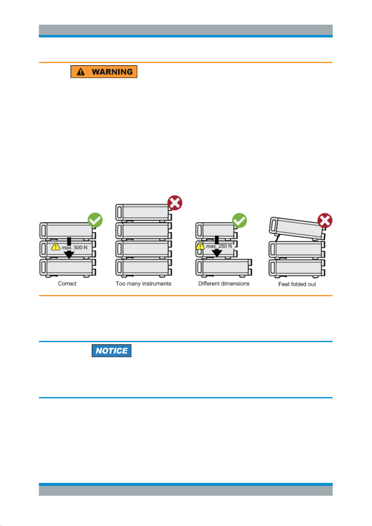
Risk of injury when stacking instruments
A stack of instruments can tilt over and cause injury if not stacked correctly. Furthermore, the instruments at the bottom of the stack can be damaged due to the load
imposed by the instruments on top.
Observe the following instructions when stacking instruments:
●
Never stack more than three instruments. If you need to stack more than three
instruments, install them in a rack.
●
The overall load imposed on the lowest instrument must not exceed 500 N.
●
It is best if all instruments have the same dimensions (width and length).
If you need to stack smaller instruments on the top, the overall load imposed on the
lowest instrument must not exceed 250 N.
●
If the instruments have foldable feet, fold them in completely.
Mounting in a rack
The R&S SMB100B can be installed in a rack using a rack adapter kit (Order No. see
data sheet). The installation instructions are part of the adapter kit.
Risk of instrument damage due to insufficient airflow in a rack
If you mount several instruments in a rack, you need an efficient ventilation concept to
ensure that the instruments do not overheat. Insufficient airflow for a longer period can
disturb the operation and even cause damage.
3.1.1.5 Connecting AC Power
The R&S SMB100B is equipped with an AC power supply connector, that can be operated with different AC power voltages. Once it is connected, the instrument automatically adjusts to the given voltage. Refer to the data sheet for the requirements of voltage and frequency. There is no need to set the voltage manually or change fuses.
23User Manual 1178.3711.02 ─ 04
R&S®SMB100B
3.1.1.6 Turning the Instrument On and Off
Getting Started
Preparing for Use
The AC supply and power switch is at the rear of the unit.
To connect the AC supply
► Connect the R&S SMB100B to the AC power source using the supplied power
cable.
Note: Since the instrument is designed in compliance with standard EN 61010-1
safety class I, it must only be connected to an outlet that has a ground contact.
Characteristics of the AC power supply:
●
100 V to 240 V AC
●
50 Hz to 60 Hz; 400 Hz
●
Max 2.1 A
To turn on the R&S SMB100B
1. Connect the instrument to the AC supply.
2. Turn on the main AC power switch at the rear panel of the R&S SMB100B (position
"I" (on)).
The instrument is supplied with AC power.
Warm-up time for OCXO
When the instrument is switched on, the OCXO requires an extended warm-up time
(see data sheet).
To start the R&S SMB100B
Starting the R&S SMB100B requires that it is connected and turned on.
► At the front panel, press the [On/Standby] key briefly.
The instrument boots the operating system and starts the instrument firmware.
After booting, the instrument is in the state before the last power off (standby or
ready), indicated by the color of the [On/Standby] key's LEDs:
● Green: the R&S SMB100B is running and ready for operation.
All modules are power-supplied.
● Orange: the R&S SMB100B is in standby mode (main AC power switch is in
position "I").
The standby power mode keeps the power switch circuits and the oven-controlled crystal oscillator OCXO active. In this state, it is safe to switch off the AC
power and disconnect the instrument from the power supply.
To switch between standby and ready state, briefly press the [On/Standby] key.
24User Manual 1178.3711.02 ─ 04
R&S®SMB100B
Getting Started
Preparing for Use
If a previous session was terminated regularly, the instrument uses the last setup with
the relevant instrument settings.
► To set up a new configuration, press the [Preset] key to return the instrument to its
defined reset/preset state.
To shut down and turn off the R&S SMB100B
Risk of losing data
If you switch off the running instrument using the rear panel switch or by disconnecting
the power cord, the instrument loses its current settings. Furthermore, program data
can be lost.
Press the On/Standby key first to shut down the application properly.
1. Press the [On/Standby] key.
The current setup is saved, the operating system shuts down and sets the instru-
ment to standby state.
The [On/Standby] LED must be orange.
2. Turn off the main AC power switch at the rear panel of the R&S SMB100B (position
"0" (off)).
The instrument is no longer supplied with AC power.
Turning off the AC power
You can leave the AC power on permanently. Switching off is required only if the instrument must be disconnected from all power supplies.
3.1.1.7 Functional Check
When the instrument is switched on, it automatically monitors the main functions.
A detected fault is indicated by an "Error" message displayed in the "Info" line of the
instrument together with a brief error description. For an in-depth identification of the
error, tap on the "Info" indication. In response, a description of the errors is displayed.
For more information, refer to the "Troubleshooting and Error Messages" section in the
user manual.
Apart from the automatic monitoring, the R&S SMB100B provides internal adjustments
to check correct functioning. See the corresponding sections under "Maintenance" in
the user manual.
25User Manual 1178.3711.02 ─ 04

R&S®SMB100B
3.1.1.8 Checking the Supplied Options and Licenses
Getting Started
Preparing for Use
The instrument can be equipped with both, hardware and firmware options. To check
whether the installed options correspond to the options indicated on the delivery note,
proceed as follows:
1. Press the [Setup] key.
2. Select "Instrument Assembly > Hardware Config" and "Software / Options".
A list with hardware and firmware information is displayed.
3. Check the availability of the hardware options as indicated in the delivery note.
For an overview of the available options, refer to the data sheet.
See also Chapter 13.3.5, "Requesting Instrument Configuration and Specifications",
on page 526.
3.1.2 Connecting USB Devices
The USB interfaces of the R&S SMB100B allow you to connect USB devices, including
USB hubs directly to the instrument. Due to the large number of available USB devices, there is almost no limit to the expansions that are possible with the
R&S SMB100B.
The following list shows various USB devices that can be useful:
●
Memory stick for easy transfer of data to/from a computer (for example firmware
updates)
●
Keyboard or mouse to simplify the entry of data, comments, filenames, etc.
●
Power sensors of the R&S NRP families
All USB devices can be connected to or disconnected from the instrument during operation.
Connecting a USB storage device
When a USB storage device like a memory stick, a CD-ROM drive, or a hard disk is
connected, it is detected automatically. The device is made available as a new drive (/
usb). The name of the drive is manufacturer-dependent.
Connecting a keyboard
A keyboard is detected automatically when it is connected. The default keyboard layout
is English – US.
Use the "Setup > User Interface > USB Keyboard Settings" dialog to configure the keyboard properties (see Chapter 10.1.4.1, "Setting the Keyboard Language",
on page 226).
26User Manual 1178.3711.02 ─ 04

R&S®SMB100B
3.1.3 Setting Up a Network (LAN) Connection
Getting Started
Preparing for Use
Connecting a mouse
A mouse is detected automatically when it is connected.
The R&S SMB100B is equipped with a network interface and can be connected to an
Ethernet LAN (local area network). Provided the appropriate rights have been assigned
by the network administrator, the interface can be used, for example:
●
To transfer data between a controller and the instrument, for example to run a
remote control program.
See Chapter 11, "Network Operation and Remote Control", on page 251.
●
To access or operate the instrument from a remote computer using the Ultr@VNC
program (or a similar tool, like another VNC client or any Web browser supporting
Java).
●
To transfer data from a remote computer and back, for example using network folders.
●
To use power sensors with network capability, e.g. the R&S NRP LAN power sensors.
This section describes how to configure the LAN interface.
Accessing operating system
No access to the operating system is required for normal operation.
All necessary system settings can be made in the "Setup" dialog.
3.1.3.1 Connecting the Instrument to the Network
There are two methods to establish a LAN connection to the instrument:
●
A non-dedicated network (Ethernet) connection from the instrument to an existing
network
●
A dedicated network connection (Point-to-point connection) between the instrument and a single computer
For addressing, both the instrument and the computer require an IP address. The
address information is usually assigned to the devices automatically, depending on the
network capabilities.
If the IP address is not assigned automatically, see Chapter 3.1.3.3, "Assigning the IP
Address", on page 29 for information on how to assign the address manually.
27User Manual 1178.3711.02 ─ 04
R&S®SMB100B
Getting Started
Preparing for Use
To set up a network (LAN) connection
Risk of network failure
Consult your network administrator before performing the following tasks:
●
Connecting the instrument to the network
●
Configuring the network
●
Changing IP addresses
Errors can affect the entire network.
► Connect the instrument to the network or to a single PC.
If the instrument is connected to the LAN, the operating system automatically
detects the network connection and activates the required drivers.
By default, the instrument is configured to use DHCP (dynamic host configuration
protocol) configuration and to obtain the whole address information automatically.
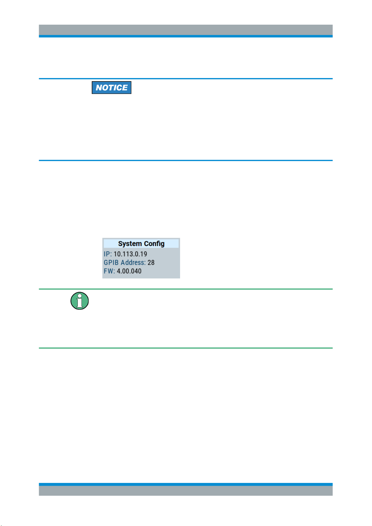
When connected, the R&S SMB100B displays the address information on the
screen.
Risk of network connection failure
Network cables and cable connectors of poor quality, or failures in the autonegotiation
process, can cause network connection failures.
If the network connection to the instrument fails, check the network infrastructure and
contact your network administrator.
For details, see section "Troubleshooting and Error Messages".
3.1.3.2 Using Computer Names (Hostnames)
In a LAN that uses a DNS server, each PC or instrument connected in the LAN can be
accessed via an unambiguous computer name (hostname) instead of the IP address.
The DNS server translates the hostname to the IP address. It is especially useful when
a DHCP server is used, as a new IP address can be assigned each time the instrument is restarted.
Each instrument is delivered with an assigned computer name, that remains permanent as long as it is not explicitly changed.
28User Manual 1178.3711.02 ─ 04

R&S®SMB100B
Getting Started
Preparing for Use
The default computer name follows the syntax <INST>-<Serial Number> (previous
syntax: rs<inst><Serial Number>), where:
●
<INST> is the short name of your instrument, as stated on the front panel.
●
<Serial Number> is the individual serial number of the instrument.
You can find the serial number at the rear panel of instrument. It is the third part of
the device ID printed on the barcode sticker .
Example:
The default hostname of an R&S SMB100B with a serial number 102030 is
SMB100B-102030.
To query and change a computer name
1. Press the [Setup] key.
2. Select "Remote Access > Network".
The computer name is displayed under "Hostname".
3. Press the [Setup] key.
4. Select "Security > Protection".
5. Enable the "Protection Level 1".
The default password is 123456.
The parameter "Hostname" in the "Network" tab is now enabled for configuration.
6. Change the "Hostname".
3.1.3.3 Assigning the IP Address
Depending on the network capacities, the TCP/IP address information for the instrument can be obtained in different ways.
●
If the network supports DHCP (dynamic host configuration protocol), the address
information is assigned automatically.
●
If the network does not support DHCP, the instrument tries to obtain the IP address
via Zeroconf (APIPA) protocol. If this attempt does not succeed or if the instrument
is set to use alternate TCP/IP configuration, the addresses must be set manually.
Since the dynamic TCP/IP configuration assigns the address information automatically,
it is safe to establish a physical connection to the LAN without any previous instrument
configuration.
29User Manual 1178.3711.02 ─ 04
R&S®SMB100B
Getting Started
Instrument Tour
Risk of network failure
Consult your network administrator before performing the following tasks:
●
Connecting the instrument to the network
●
Configuring the network
●
Changing IP addresses
Errors can affect the entire network.
To assign the IP address manually on the instrument
Use computer names to identify the instrument
In networks using a DHCP server, we recommend that you address the instrument by
its unambiguous computer name, see Chapter 3.1.3.2, "Using Computer Names (Host-
names)", on page 28.
1. Press the [Setup] key.
2. Select "Remote Access > Network".
3. Select "Address Mode > Static".
4. Select the "IP Address".
5. Enter the IP address, for example 192.168.0.1.
The IP address consists of four number blocks separated by dots. Every block con-
tains 3 numbers in maximum.
6. Select the "Subnet Mask" and enter the subnet mask, for example 255.255.255.0.
The subnet mask consists of four number blocks separated by dots. Every block
contains 3 numbers in maximum.
To assign the IP address manually on the computer
► Obtain the necessary information from your network administrator. If you use more
than one LAN connector, you need separate address information for each connector.
For information on how to perform the configurations, refer to the documentation of
the operating system the computer uses.
3.2 Instrument Tour
The following topics help you to get familiar with the instrument and perform the first
steps:
●
Chapter 3.2.1, "Front Panel Tour", on page 31
30User Manual 1178.3711.02 ─ 04

R&S®SMB100B
3.2.1 Front Panel Tour
Getting Started
Instrument Tour
●
Chapter 3.2.2, "Rear Panel Tour", on page 36
This section explains the control elements and the connectors of the R&S SMB100B
with the aid of the front and rear views. For specifications of the interfaces, refer to the
data sheet.
This section provides an overview of the control elements at the front panel of the
R&S SMB100B. Most of the connectors are at the rear panel and are described in
Chapter 3.2.2, "Rear Panel Tour", on page 36.
Figure 3-1: Front panel view
1 = Utility keys
2 = [On/Standby]
3 = Touchscreen
4 = Function keys
5 = Keypad
6 = Navigation controls
7 = Display keys
8 = USB connector
9 = RF output connector
3.2.1.1 Touchscreen
The screen at the front panel is the graphical user interface. It shows the settings dialogs and parameters, and the current configuration at a glance, see Chapter 3.4.3,
"Understanding the Display Information", on page 48.
31User Manual 1178.3711.02 ─ 04

R&S®SMB100B
Getting Started
Instrument Tour
Figure 3-2: Touchscreen
The touch-sensitive panel provides an alternative means of user interaction for quick
and easy handling of the instrument, see Chapter 3.4.2, "Means of Manual Interaction",
on page 47.
Risk of touchscreen damage
Inappropriate tools or excessive force can damage the touchscreen.
Observe the following instructions when operating the touchscreen:
●
Never touch the screen with ball point pens or other sharp objects, use your fingers
instead.
As an alternative, you can use a stylus pen with a smooth soft tip.
●
Never apply excessive force to the screen. Touch it gently.
●
Never scratch the screen surface, for example with a finger nail.
●
Never rub the screen surface strongly, for example with a dust cloth.
For instructions on cleaning the screen, see Chapter 13.1, "Cleaning",
on page 515.
3.2.1.2 Utility Keys
The utility keys set the R&S SMB100B to a defined state, and provide access to basic
settings and information on assistance.
32User Manual 1178.3711.02 ─ 04

R&S®SMB100B
3.2.1.3 On/Standby
Getting Started
Instrument Tour
Table 3-1: Utility keys
Utility Key Assigned functions
[Preset] Sets the instrument to a defined state
[Local] Switches from remote control to local (manual) control
[Setup] Accesses the general instrument settings
[Help] Displays context-sensitive help text
The [On/Standby] key starts up and shuts down the instrument, and switches between
the standby and the ready state.
●
In the ready state, On/Standby key lights green. The instrument is ready for operation.
●
In the standby state, the On/Standby key lights orange. The standby power mode
keeps the power switch circuits and the oven-controlled crystal oscillator OCXO
active. In this state, it is safe to switch off the AC power and disconnect the instrument from the power supply.
3.2.1.4 Function Keys
Function keys provide access to the most common generator settings and functions.
You can find a detailed description of the corresponding functions in the user manual.
Table 3-2: Function keys
Function key Assigned functions
[Freq] Activates frequency entry.
[Level] Activates level entry.
[Mod on/off] Switches the modulation on and off.
[RF on/off] Switches the RF output on and off.
3.2.1.5 Keypad
The keypad enables you to enter alphanumeric parameters, including the corresponding units. It contains the following keys:
Table 3-3: Keys on the keypad
Type of key Description
Alphanumeric keys Enter numbers and (special) characters in edit dialog boxes.
Decimal point Inserts a decimal point "." at the cursor position.
33User Manual 1178.3711.02 ─ 04

R&S®SMB100B
Getting Started
Instrument Tour
Type of key Description
Sign key Changes the sign of a numeric parameter. In the case of an alphanu-
meric parameter, inserts a "-" at the cursor position.
Unit keys
(G/n dBμV, M/μ μV, k/m mV and
x1 dB(m))
3.2.1.6 Navigation Controls
The navigation controls include a rotary knob, navigation keys, and the display keys.
They allow you to navigate within the display or within dialog boxes.
Rotary Knob
The rotary knob has several functions:
●
Increments (clockwise direction) or decrements (counterclockwise direction) the
instrument parameter at a defined step size in the case of a numeric entry.
●
Moves the selection, e.g. to a function block in the block diagram
●
Shifts the selection bar within focused areas (e.g. lists).
●
Acts like the [Enter] key, when it is pressed.
Editing Keys
Editing keys enable you to confirm an entry, delete individual characters, or exit the
current operation.
These keys add the selected unit to the entered numeric value and complete the entry.
In the case of level entries (e.g. in dB) or dimensionless values, all units
have the value "1" as multiplying factor. Thus, they have the same function as an [Enter] key.
Table 3-4: Editing keys
Type of key Description
[Esc] key Closes all kinds of dialog boxes, if the edit mode is not active. Quits the
edit mode, if the edit mode is active. In dialog boxes that contain a "Cancel" button it activates that button.
For "Edit" dialog boxes the following mechanism is used:
●
If data entry has been started, it retains the original value and
closes the dialog box.
●
If data entry has not been started or has been completed, it closes
the dialog box.
[Enter] key
[Backspace] key Deletes the character to the left of the cursor in editing mode.
Has the same effect as pressing the rotary knob
●
Concludes the entry of dimensionless entries. The new value is
accepted.
●
With other entries, this key can be used instead of the default unit
key.
●
In a dialog box, selects the default or focused element.
●
Calls the next dialog level.
●
Confirms and closes open input windows.
34User Manual 1178.3711.02 ─ 04

R&S®SMB100B
Getting Started
Instrument Tour
Navigation Keys
As an alternative to the rotary knob or the touchscreen, you can use the navigation
keys to navigate through dialog boxes, diagrams, or tables.
Table 3-5: Navigation keys
Type of key Description
[Up/Down] Key The [Up] and the [Down] key does the following:
[Left/Right] Key The [Left] and the [Right] key does the following:
3.2.1.7 Display Keys
The display keys arrange different windows on the display.
Table 3-6: Display keys
Display key Assigned functions
[Home] Returns to the initial feature screen.
[Next window] Toggles between the entry fields in the taskbar.
[On/Off]
●
In a numeric edit dialog box, increase or decrease the instrument
parameter.
●
In a list, scroll forward and backward through the list entries.
●
In a table, move the selection bar vertically.
●
In windows or dialog boxes with vertical scrollbar, move the scrollbar.
●
In an alphanumeric edit dialog box, move the cursor.
●
In a list, scroll forward and backward through the list entries.
●
In a table, move the selection bar horizontally.
●
In windows or dialog boxes with horizontal scrollbar, move the
scrollbar.
●
Switches highlighted elements or a function block on and off.
●
Switches between two or more settings, e.g. items of selection lists.
At the end of a list, the cursor is set on the first entry again.
[Undo] Reverts the last operation.
[★ (User)] Adds a parameter to the user menu for quick access.
3.2.1.8 USB Connector
USB (universal serial bus) interfaces of type A (host USB).
●
Connection of peripherals such as mouse or keyboard
●
Connection of memory stick for file transmission
●
Firmware update
Further USB interface type A (host USB) and a USB interface type B (USB In) are
available on the rear panel.
See also Chapter 3.1.2, "Connecting USB Devices", on page 26.
35User Manual 1178.3711.02 ─ 04

R&S®SMB100B
3.2.1.9 RF 50 Ω
Getting Started
Instrument Tour
Output of the RF signal.
Maximum input levels
Do not overload the RF output.
The instrument is equipped with a reverse power protection that prevents the RF out-
put against back feed, see Chapter 7.1.2, "Reverse Power Protection", on page 149.
The maximum permissible reverse power is specified in the data sheet.
The connector type depends on the installed frequency option.
Risk of RF connector and cable damage
If you tighten the connectors too strongly, you can damage the cables and connectors.
If you do not tighten the connectors enough, the measurement results can be inaccurate.
Always use an appropriate torque wrench suitable for this type of connector and apply
the torque specified in the application note 1MA99.
The application notes are available on the Internet and provide additional information
on care and handling of RF connectors.
Rohde & Schwarz offers appropriate torque wrenches for various connectors. For
ordering information, see the R&S SMB100B data sheet or product brochure.
3.2.2 Rear Panel Tour
This section provides an overview of the connectors at the rear panel of the instrument.
For technical data of the connectors, refer to the data sheet.
Figure 3-3: Rear panel view R&S
SMB100B RF Signal Generator
36User Manual 1178.3711.02 ─ 04

R&S®SMB100B
3.2.2.1 Connectors
Getting Started
Instrument Tour
1 = IEC 625/IEEE 488 connector
2 = USB In connector (type micro-B)
3 = LAN connector
4 = USB connector (type A)
5 = AC power supply connection and main power switch
6 = S/P Dif digital stereo signal input connector (BNC)
7 = Stereo L/R analog stereo modulation signal input connectors (BNC)
8 = Ref In 1GHz and Ref Out 1GHz connectors (SMA)
9 = Ref In and Ref Out connectors (BNC)
10 = LF output connector (BNC)
11 = Mod. Ext. input connector (BNC)
12 = Pulse Video and Pulse Ext. connectors (BNC)
13 = Signal Valid output connector (BNC)
14 = Inst Trig input connector (BNC)
15 = Serial number (six digits in the string 1400.1000.02-<serial number>-<checksum>)
IEC 625/IEEE 488
Option: R&S SMBB-B86
GPIB-bus interface for remote control of the instrument.
The IEC 625 interface is in compliance with IEEE488 and SCPI. A computer for remote
control can be connected via this interface. To set up the connection, we recommend
that you use a shielded cable.
Note: To avoid electromagnetic interference (EMI) caused by open lines, always terminate any connected IEC-bus cable with an instrument or a controller.
See also Chapter B.1, "GPIB-Bus Interface", on page 565 and Chapter 11, "Network
Operation and Remote Control", on page 251.
USB/USB In
●
Female USB type A connector, to connect devices like a keyboard, a mouse, a
memory stick, or the R&S NRP-Z3/Z4 cable for the R&S NRP power sensors
●
Female USB In connector (USB type B), for example for remote control.
Option: R&S SMBB-B86
See also Chapter 3.1.2, "Connecting USB Devices", on page 26.
LAN
The LAN interface can be used to connect the R&S SMB100B to a local network for
remote control, remote operation, and data transfer.
For details, see Chapter 3.1.3, "Setting Up a Network (LAN) Connection", on page 27.
AC supply and power switch
The AC power supply connector and the main power switch are located in a unit on the
rear panel of the instrument.
Main power switch function:
●
Position 1: The instrument is in operation.
●
Position 0: The entire instrument is disconnected from the AC power supply.
For details, refer to Chapter 3.1.1.6, "Turning the Instrument On and Off", on page 24.
37User Manual 1178.3711.02 ─ 04

R&S®SMB100B
Getting Started
Trying Out the Instrument
S/P Dif
Input for digital stereo signals (stereo modulation is available with option R&S SMBBB5).
See also Chapter 5.4.3, "Stereo Modulation", on page 78.
Stereo L/R
Inputs for analog stereo modulation signals. External modulation sources or the internal LF generator can be used (stereo modulation is available with option R&S SMBBB5).
See also Chapter 5.4.3, "Stereo Modulation", on page 78.
Ref In/Ref Out
Input/output for external reference signal.
Incl. dedicated connectors for the 1GHz reference signal.
See Chapter 8, "Reference Oscillator", on page 178.
Mod. Ext.
Input for an external analog modulation signal.
Pulse Video
Output of the internal pulse generator signal or the looped through pulse signal from
Pulse Ext. connector (video signal).
See Chapter 5.4.1, "Pulse Modulation", on page 71.
Pulse Ext.
Input for an external pulse modulation signal or an external trigger/gate signal for the
pulse generator.
Signal Valid
Output signal that marks the valid signal times (valid level and frequency) for all analog
modulations.
Alternatively, you can use this connector to synchronize pulse signals by activating the
"Pulse Sync" in the dialog Chapter 5.4.4, "Pulse Generator", on page 86.
Inst Trig
Input for external trigger of sweeps and list mode.
For detailed information on the sweep modes and the triggering, see Chapter 6.1, "Sig-
nal Generation and Triggering in the Sweep and List Modes", on page 112.
3.3 Trying Out the Instrument
This chapter introduces the first steps with the R&S SMB100B. It shows how to operate and configure the instrument using simple examples. The complete description of
the functionality and its usage is given in the R&S SMB100B user manual. Basic instrument operation is described in Chapter 3.4, "Instrument Control", on page 46.
38User Manual 1178.3711.02 ─ 04

R&S®SMB100B
3.3.1 Generating an Unmodulated Carrier
Getting Started
Trying Out the Instrument
Prerequisites
The instrument is set up, connected to the power supply, and started up as described
in Chapter 3.1, "Preparing for Use", on page 20.
The first signal generation tasks explain how to generate an unmodulated signal, to
configure the RF signal output, and how you can vary the RF frequency and level in
sweep mode.
The instrument is manually operated via the touchscreen. Try out the following:
● Generating an Unmodulated Carrier.......................................................................39
● Generating an RF Frequency Sweep Signal...........................................................41
● Saving and Recalling Settings................................................................................ 43
We start to generate a simple unmodulated signal. In this example, the R&S SMB100B
can be in its minimal configuration.
1. On the R&S SMB100B front panel, press the [Preset] key to set a defined initial
instrument state.
2. Set the frequency:
a) In the "Status Bar", tap the "Frequency" field.
b) On the on-screen keypad, enter "6" and press the "GHz" key.
The on-screen key pad closes and the frequency value is displayed.
3. To set the signal level, tap the "Level" field and enter the level in the same way.
4. To activate RF signal output, select "Level" > "RF On" in the tile diagram.
39User Manual 1178.3711.02 ─ 04

R&S®SMB100B
Getting Started
Trying Out the Instrument
The blue colored "RF On" icon indicates that the RF output is activated.
The R&S SMB100B provides the 6 GHz signal at the RF connector at the front
panel.
Figure 3-4: Generating an unmodulated signal
40User Manual 1178.3711.02 ─ 04

R&S®SMB100B
Getting Started
Trying Out the Instrument
Alternative ways to access the instrument functions
To fulfill the same task, you can also use the front panel keys or the setting parameters
provided in the frequency and level dialogs.
Try out the settings dialogs
1. In the "Frequency" tile, select "Frequency...".
a) In the "RF Frequency" tab, tap the "Frequency" field.
b) Set the frequency via the on-screen keypad.
2. Access the "RF Level" dialog via the "Level" tile.
a) In the "RF Level" tab, select "Amplitude".
b) Set the amplitude (level) via the on-screen keypad.
3. Select "RF State > On" to activate the RF signal generation.
See Chapter 4, "RF Signal Configuration", on page 57.
Try out the front panel keys
► Use the [Freq], [Level], and [RF on/off] key on the front panel.
Connect RF of the R&S SMB100B to a signal analyzer, for example R&S®FSW, to display the generated signal.
For the required settings of the signal analyzer, refer to its user manual or its online
help.
3.3.2 Generating an RF Frequency Sweep Signal
The "Sweep" operating mode allows you to generate an RF signal with periodically
varying frequencies or amplitudes.
This example deals with an RF signal with varying frequency and constant level. To
configure the sweep, you need to determine a defined start and end frequency with
constant time intervals between the frequency steps.
The sweep function does not require specific options.
1. On the front panel, press the [Preset] key to set a defined initial instrument state.
2. Set the signal output level, if required, e.g. set "Level > -25 dBm".
3. In the tile diagram, select "Sweep" > "Frequency Sweep".
4. In the "General" tab:
41User Manual 1178.3711.02 ─ 04

R&S®SMB100B
Getting Started
Trying Out the Instrument
a) Select "Mode > Auto" to run the sweep continuously.
b) Select "Shape > Sawtooth" to set the waveform shape of the sweep signal.
c) Select "Spacing > Linear", to determine the calculation method for the fre-
quency shift of a step.
d) Set "Dwell Time > 15.0 ms", to determine the time interval of the sweep steps.
5. Select the "Frequency Range" tab.
a) Set "Start Freq > 200 MHz" and "Stop Freq > 600 MHz" to determine the fre-
quency sweep range.
b) Set the step width "Step Lin > 10.0 MHz" to determine the width for a frequency
step.
6. In the "General" tab, activate the frequency sweep with "State > On".
7. Close the sweep dialog.
(Alternatively, tap the "Home" button to minimize the dialog. The R&S SMB100B
indicates the "Sweep" dialog as active dialog in the task bar.)
8. To activate the RF signal output, select "Level" > "RF On".
42User Manual 1178.3711.02 ─ 04

R&S®SMB100B
Getting Started
Trying Out the Instrument
Figure 3-5: Generating a frequency sweep signal
The frequency field in the status bar indicates the continuously changing frequency,
i.e. the running sweep.
3.3.3 Saving and Recalling Settings
To restore the results of our measurements later, we save the instrument settings in a
file.
To save the instrument settings in a file
We assume, a test configuration as described in Chapter 3.3.2, "Generating an RF
Frequency Sweep Signal", on page 41.
1. Press the [Setup] key on the front panel.
2. In the "Setup" menu, select "Settings > Save/Recall".
3. In the "Save/Recall" dialog, select "Operation Mode > Save".
43User Manual 1178.3711.02 ─ 04

R&S®SMB100B
Getting Started
Trying Out the Instrument
4. Tap the "Filename", use the on-screen keyboard, and enter MyTestSignal.
5. Tap the "Save" button.
The file MyTestSignal.savrcltxt is stored in the default directory /var/user/.
To load saved instrument settings
You can restore the settings to the instrument at any time using the settings file.
1. Press the [Preset] button to restore the default instrument settings so you can
check that the stored user settings are restored afterwards.
2. Press the [Setup] key on the front panel.
3. In the "Setup" menu, select "Settings > Save/Recall".
4. In the "Save/Recall" dialog, select "Operation Mode > Recall".
Navigate to the directory the file is saved in and select the MyTestSignal file.
44User Manual 1178.3711.02 ─ 04

R&S®SMB100B
Getting Started
Trying Out the Instrument
5. Tap the "Recall" button.
All instrument settings are restored and the display resembles Chapter 3.3.2, "Gen-
erating an RF Frequency Sweep Signal", on page 41, which shows the instrument
display right before the settings were saved.
How to display all parameters with values different to their preset values
When you load a file to your instrument, you do not have enough information on the
changed settings. In such case, it is useful to visualize all parameters that have been
changed from their default state.
Try out the following:
●
Touch and hold a spot in the tile diagram for at least 1 second to access the context-sensitive menu.
●
Select "Mark All Parameters Changed from Preset".
45User Manual 1178.3711.02 ─ 04

R&S®SMB100B
Getting Started
Instrument Control
●
All changed parameters are highlighted.
See also
Chapter 9, "File and Data Management", on page 187.
3.4 Instrument Control
This chapter provides an overview on how to work with the R&S SMB100B.
It covers the following topics:
46User Manual 1178.3711.02 ─ 04

R&S®SMB100B
3.4.1 Possible Ways to Operate the Instrument
Getting Started
Instrument Control
● Possible Ways to Operate the Instrument...............................................................47
● Means of Manual Interaction...................................................................................47
● Understanding the Display Information...................................................................48
● Accessing the Functionality.....................................................................................51
● Entering Data.......................................................................................................... 52
● Getting Information and Help.................................................................................. 53
● Remote Control.......................................................................................................55
● Remote Operation over VNC.................................................................................. 56
There are three ways to operate the R&S SMB100B:
●
Manual operation:
Use the touchscreen, hard keys and rotary knob, or an optional mouse and/or keyboard.
The description under Chapter 3.4, "Instrument Control", on page 46 shows how to
operate the instrument manually.
●
Remote control:
Create programs to automatize repeating settings, tests and measurements. The
instrument is connected to a computer running the program.
This way of operation is described in Chapter 11, "Network Operation and Remote
Control", on page 251.
●
Remote operation from a computer:
Remote monitoring and control of the instrument from a connected computer is
based on the common cross-platform technology VNC (Virtual Network Computing). On the remote computer, any standard web browser (supporting Java) or a
dedicated VNC client (like Ultr@VNC) can be used. See also Chapter 3.4.8,
"Remote Operation over VNC", on page 56.
3.4.2 Means of Manual Interaction
For the manual interaction with the R&S SMB100B, you have several methods that you
can use as an alternative to perform a task:
●
Touchscreen:
Touchscreen operation is the most direct way to interact. Almost all control elements and actions on the screen are based on the standard operating system concept. You can tap any user interface element to set parameters in dialog boxes,
enter data, scroll within a dialog etc., as if you work with a mouse pointer.
Tapping the screen works like clicking mouse buttons:
– Touch quickly = click: Selects a parameter or provokes an action.
– Touch and hold = right-click: Opens a context-sensitive menu.
– Touch and swipe = drag: Scrolls through the contents of a display element
larger than the screen, e.g. a list or a table.
●
Function keys and rotary knob:
The front panel provides nearly all functions and controls to operate the instrument
in the classic way, without touchscreen.
47User Manual 1178.3711.02 ─ 04

R&S®SMB100B
3.4.3 Understanding the Display Information
Getting Started
Instrument Control
●
Optional mouse and/or keyboard:
These devices work like known from PCs. The navigation keys on the front panel
correspond to the keys on the keyboard.
This manual describes the manual interaction with the instrument via the touchscreen.
It mentions the alternative methods using the keys on the instrument or the on-screen
keypads if it deviates from the standard operating procedures. The usage of the touchscreen and navigation keys is described in Chapter 3.4.4, "Accessing the Functional-
ity", on page 51.
Throughout the manual, the term "select" refers to any of the described methods, i.e.
using a finger on the touchscreen, a mouse pointer in the display, or a key on the
instrument or on a keyboard.
The home screen of the R&S SMB100B displays all main settings and generator
states, divided into three main operation areas.
Figure 3-6: Home screen
1 = Taskbar/softkey bar with "Home" and "Info" key
2 = Status bar
3 = Tile diagram
● Status Bar............................................................................................................... 49
● Tile Diagram............................................................................................................49
● Taskbar....................................................................................................................49
● Additional Display Characteristics...........................................................................50
48User Manual 1178.3711.02 ─ 04

R&S®SMB100B
3.4.3.1 Status Bar
3.4.3.2 Tile Diagram
Getting Started
Instrument Control
The status bar at the top of the screen indicates the RF frequency and the level of the
output signal provided to the DUT. You can set both parameters directly here.
The tile diagram is the main entry to the settings of the R&S SMB100B.
Tile Access to:
"Modulation"
"System Config"
"Sweep"
"Frequency"
"Level"
"Power sensors"
1)
requires additional options
3.4.3.3 Taskbar
The "Taskbar" shows a home and an info button, and assigns a labeled button whenever you open a dialog. If more dialogs are open than the taskbar can display, touch
and swipe the taskbar to scroll up and down.
●
Analog and stereo1), and pulse1) modulation settings
●
Built in LF generator
●
"Save/Recall": settings for saving and loading instrument configurations
●
"Remote access": Network and emulation settings.
●
"Setup": general system configuration
●
Frequency and level sweeps
●
List mode
●
RF frequency and phase
●
Reference frequency
●
RF level
●
Attenuator
●
Automatic level control
●
User correction
●
Power sensors
The buttons shown in the following example represent the variants.
Table 3-7: Example of buttons in the taskbar
"Home" button
Returns to the home screen.
"User Menu"
Lists parameters that can be defined for quick access.
Shows the current remote access connections when the instrument is remotely controlled.
Tip: An indicator in the "System Config" tile shows the current remote control status.
R&S NRP power sensors
Shows a connected external power sensor. The button displays the current readings
when the sensor is active.
49User Manual 1178.3711.02 ─ 04

R&S®SMB100B
3.4.3.4 Additional Display Characteristics
Getting Started
Instrument Control
Active dialogs
Indicates the dialog name of each active dialog in a separate button.
"Info" key
Provides access to status and error messages.
Note: The warning symbol signifies a permanent error message.
The following section provides a short insight on the indication of the screen in general,
and significant elements that you see under specific operating modes, in dialogs or settings.
●
Appearance of active elements
– Active elements like On/Off switches, state buttons have a blue background.
– Selected elements are framed or highlighted orange.
– Inactive elements are gray.
●
On-Screen keypads
As additional means of interacting with the instrument without having to connect an
external keyboard, either a numerical or alphanumerical on-screen keypad appears
when you activate an entry field (see Chapter 3.4.5, "Entering Data",
on page 52).
●
Info line
The "Info line" shows brief status information and error messages. It appears when
an event generates a message.
●
Key parameters indicated in tab labels
Most dialogs are divided into tabs with logically grouped parameters. The tab label
expresses the content and can also contain status indicators or the set value of a
key parameter.
●
Scroll bar handle
An arrow icon that appears when you touch a scroll bar helps you to scroll in a dialog or list.
If no scrollbar handle appears, you can touch and swipe an element to scroll up
and down.
●
Context-sensitive menus
Within the entire screen display, including single parameters, you can access context-sensitive menus that provide some additional functions.
50User Manual 1178.3711.02 ─ 04

R&S®SMB100B
Getting Started
Instrument Control
3.4.4 Accessing the Functionality
All functionalities are provided in dialog boxes as known from computer programs. You
can control the instrument intuitively with the touchscreen. This section provides an
overview of the accessing methods.
The instrument's functions and settings can be accessed by selecting one of the following elements:
●
System and function keys on the front panel of the instrument
●
Taskbar/softkeys on the touchscreen
●
Context-sensitive menus for specific elements on the touchscreen
●
Elements on the status bar in the touchscreen
●
Displayed setting on the touchscreen, that means block diagram and all settings
available in dialogs.
To open a dialog box
► Perform one of the following actions:
● Tap the required tile, and then the menu entry.
● Tap the minimized view (button) on the taskbar.
Some of the utility keys access a dedicated dialog, too.
To minimize a dialog box
1. To return to the home screen, tap the "Home" button.
51User Manual 1178.3711.02 ─ 04

R&S®SMB100B
3.4.5 Entering Data
Getting Started
Instrument Control
2. To switch to another dialog, press the [Next Window] button.
To close a dialog box
To close a dialog box, you have the same controls as you know from computers or
devices with touchscreen.
► Perform one of the following actions:
● Tap the "Close" icon in the upper right corner.
● Press the [Esc] key on the front panel.
● Drag and drop a minimized dialog from the taskbar to the tile diagram.
To select an option in a dialog box
► Tap the required option.
Some parameters have their own key on the front panel.
For data input in dialog boxes, the instrument provides on-screen keypads for entering
numeric and alphanumeric values. Thus, you can always set the parameters via the
touchscreen, the front panel, or an external keyboard.
Correcting an entry
1. Using the arrow keys, move the cursor to the right of the entry you want to delete.
2. Press the [Backspace] key.
3. Deletes the entry to the left of the cursor.
4. Enter your correction.
Completing the entry
► Press the [Enter] key or the rotary knob.
Aborting the entry
► Press the [Esc] key.
The dialog box closes without changing the settings.
52User Manual 1178.3711.02 ─ 04

R&S®SMB100B
3.4.5.1 Entering Numeric Parameters
Getting Started
Instrument Control
To enter values with the on-screen keypad
For numeric settings, the instrument displays the numeric keypad. The units specified
correspond to the units of the parameter.
1. Enter the numeric value.
2. Tap the unit button to complete the entry.
The unit is added to the entry.
3. If the parameter does not require a unit, confirm the entered value by pressing
"Enter".
To enter values by using the front panel controls
1. Change the currently used parameter value by using the rotary knob or the [Up/
Down] keys.
2. If the parameter does not require a unit, confirm the entered value by pressing the
[Enter] key or any of the unit keys.
The instrument highlights the editing line to confirm the entry.
If you edit numeric data in tables, the entry field must be in edit mode: Press [Enter], or
the rotary knob to activate the edit mode.
3.4.5.2 Entering Alphanumeric Parameters
If a field requires alphanumeric input, you can use the on-screen keyboard to enter letters and (special) characters.
3.4.5.3 Undo and Redo Actions
Accessed via the context-sensitive menus, "Undo" allows you to restore one or more
actions on the instrument. Depending on the available memory, the "Undo" steps can
restore all actions.
"Redo" restores a previously undone action.
3.4.6 Getting Information and Help
In some dialog boxes, graphics are included to explain the way a setting works.
53User Manual 1178.3711.02 ─ 04

R&S®SMB100B
Getting Started
Instrument Control
For further information, you can use the following sources:
●
Tooltips give the value range of the parameter.
●
The context help provides functional description on a setting.
●
The general help explains a dialog box, provides instructions, and general information.
To display context help
► To access a help topic, perform one of the following:
a) Tap and hold the parameter for which you need information and tap "Help" in
the context menu.
b) Tap the parameter and press the [Help] key.
The "Help" dialog opens. You can browse the help for further information.
Contents of the help dialog box
The help dialog box covers two main areas:
●
"Contents" - contains a table of help contents
●
"Topic" - contains a specific help topic
The help system also provides an "Index" and a "Find" area, and "Zoom" functions that
are accessed via the corresponding buttons.
To open general help
► Press the yellow [Help] key on the front panel.
If a dialog box is opened, the help topic for the current tab is shown. Otherwise the
"Contents" page appears.
54User Manual 1178.3711.02 ─ 04

R&S®SMB100B
Getting Started
Instrument Control
Navigating in the table of contents and in the help topics
1. To move through the displayed contents entries, tap on an entry and scroll or use a
connected mouse or the [Up/Down] keys.
Entries with a plus sign contain further entries.
2. To display a help topic, tap on the topic name or double click on the topic name or
press the [Enter] key.
3. To follow a cross-reference, tap on the link text.
4. To return to the previous page, select "Back".
This function scrolls back all steps you have performed before.
5. Use the "scroll bars" to shift the visible section of content shown.
6. To maximize the "Topics" area, tap the "Hide Contents Tree" button to hide the contents tree.
Using the index
1. Select the "Index" button.
2. Enter the first characters of the topic you are interested in.
The entries starting with these characters are displayed.
3. Tap on the index entry.
The corresponding help topic is displayed.
3.4.7 Remote Control
In addition to working with the R&S SMB100B interactively, located directly at the
instrument, it is also possible to operate and control it from a remote PC.
The R&S SMB100B supports various methods for remote control:
●
Connecting the instrument to a (LAN) network (see Chapter 3.1.3, "Setting Up a
Network (LAN) Connection", on page 27)
●
Using the LXI browser interface in a LAN network
●
Connecting a PC via the IEC-bus (IEEE 488) interface
●
Remote control via the USB interface
For remote control over LAN or USB, you can use the R&S VISA (Virtual Instrument
Software Architecture) library provided for download at the Rohde & Schwarz website
http://www.rohde-schwarz.com/rsvisa.
How to configure the remote control interfaces is described in Chapter 11, "Network
Operation and Remote Control", on page 251.
55User Manual 1178.3711.02 ─ 04

R&S®SMB100B
3.4.8 Remote Operation over VNC
Getting Started
Instrument Control
The VNC is an application which can be used to access and control the instrument
from a remote computer through a LAN connection. While the instrument is in operation, the instrument screen contents are displayed on the remote computer, and VNC
provides access to all applications, files, and network resources of the instrument.
Thus, remote operation of the instrument is possible.
Instrument control from a remote computer
To access the basic utility functions of the R&S SMB100B, perform a right mouse click
on the block diagram and select "Key Emulation".
A key panel to the right of the block diagram gives access to the utility functions provided by the front panel keys.
The VNC is an add-on program, included in operating system Linux/Unix, and available
as a free-of-charge download on the internet.
For more information, refer to Chapter 11.16, "How to Set Up Remote Operation via
VNC", on page 300.
56User Manual 1178.3711.02 ─ 04

R&S®SMB100B
4 RF Signal Configuration
RF Signal Configuration
The R&S SMB100B signal generator generates RF signals with outstanding spectral
purity within the frequency range from 8 kHz up to 6 GHz and with adjustable signal
level over a wide range.
In addition to these real-time CW signals, you can generate RF signals from predefined
lists and sweep signals that vary according to the frequency or amplitude curves.
You can also apply versatile analog modulation types with definable characteristics.
The variably adjustable output level due to the built-in attenuator, allows you to vary the
RF signal level over the full level range. There are different methods to improve signal
performance and to optimize the signal quality for the particular application, or to
increase the accuracy and reliability of the generated RF signal.
The R&S SMB100B supports R&S NRP power sensors, e.g. to monitor the output level
of the generator or to determine the level correction values for user correction lists.
Signal modes and characteristics
The R&S SMB100B generates unmodulated or analog modulated RF signals. You can
output the signal in fixed mode or as a signal having periodically varying frequencies or
amplitudes.
Signal modes for RF signal generation:
●
Unmodulated signal
Generates an unmodulated continuous wave (CW) of constant frequency and
amplitude.
For information on the signal frequency and level settings and an example on how
to configure a simple CW signal, see:
– Chapter 4.3, "RF Frequency Settings", on page 60
– Chapter 4.4, "RF Level Settings", on page 62
– Chapter 3.3.1, "Generating an Unmodulated Carrier", on page 39
●
Analog modulated signal
Modulates the signal with an analog signal and generates amplitude, phase, frequency and pulse modulation.
See Chapter 5, "Analog Modulations", on page 68.
The R&S SMB100B allows you to provide the RF signal with constant or varying frequencies and/or amplitudes at the output:
●
Constant frequency and level (CW/Fixed mode)
The RF output signal has the set frequency and level.
●
Varying frequency and/or level
– Sweep mode
An RF or LF frequency and RF level sweep signal, processed continuously,
step-by-step or individually and with selectable trigger modes. You can only run
one sweep at a time.
– List mode
57User Manual 1178.3711.02 ─ 04

R&S®SMB100B
4.1 Activating RF Signal Output
RF Signal Configuration
How to Set the Frequency and Level
The RF signal is based on a list of predefined frequency and level values pairs
and step widths.
See Chapter 6, "List and Sweep Mode", on page 110.
Per default, the RF output signal is deactivated.
To activate the RF output
1. Configure the RF signal as required.
Set, for example, the frequency and level values.
2. Activate the RF output in one of the following ways:
a) Select "Level > RF ON > On"
b) Press the [RF on/off] key at the front panel.
3. In the "Level" tile, observe the color of the "RF On" icon.
The blue color indicates that the RF output is activated.
RF State/RF ON............................................................................................................58
RF output impedance....................................................................................................58
RF State/RF ON
Activates or deactivates the RF output.
Acts as the [RF on/off] key.
Remote command:
:OUTPut<hw>[:STATe] on page 345
RF output impedance
You can query the impedance of the RF output.
Remote command:
:OUTPut<hw>:IMPedance? on page 346
4.2 How to Set the Frequency and Level
The simplest form of the RF signal is a continuous wave (CW) of constant frequency
and amplitude. The RF signal is defined by its frequency, level and phase.
► Use one of the following:
● "Status Bar > Frequency and Level"
● "Frequency panel > Frequency"
● "Level panel > Level"
● "Frequency panel > Frequency > Phase"
58User Manual 1178.3711.02 ─ 04

R&S®SMB100B
RF Signal Configuration
How to Set the Frequency and Level
● On the front panel, press the [Freq] or the [Level] key.
Current frequency and level values are indicated in the "Status bar" so that you can
see them at a glance. Values displayed in the status bar and in the "Frequency/Level"
dialogs can deviate from each other.
See "RF frequency and level display with a downstream instrument" on page 59.
RF frequency and level display with a downstream instrument
If your test setup includes a downstream instrument, you can enter the parameter of
the downstream instrument in the frequency or level settings dialog of the
R&S SMB100B. Examples of downstream instruments are mixers, frequency multipliers, amplifiers or attenuators and of their corresponding major parameters offset, multiplier, amplitude. The R&S SMB100B generates the signal without the downstream
parameters, but considers all additional parameters concerning the frequency and
level.
Example parameters that affect the frequency and level:
●
Frequency offset
●
Multiplication factor
●
User correction
Any of these cases are indicated by a dedicated icon, displayed in the "Frequency" or
"Level" tile, depending on the affected parameter.
Figure 4-1 illustrates the calculation of the "Frequency" and "Level" values, displayed
in the status bar.
Figure 4-1: Frequency and Level display vs frequency and level at the RF output
fRF, Level
f
, Level
RF Out
Out
n*f = Multiplication factor ("RF > RF Frequency > Multiplier")
Δf = Frequency offset ("RF > RF Frequency > Offset")
ΔLevel = Power offset ("RF > RF Level > Offset")
= Frequency and level ("Status bar > Frequency and Level") at the output of the downstream
RF
instrument, see also Calculation of fRF and LevelRF)
= Frequency and level at the output connector [RF] ("RF > RF Frequency > Frequency" and
RF
"RF > RF Level > Amplitude")
Calculation of fRF and Level
●
fRF =n*f
●
LevelRF = Level
RF Out
+ Δf
RF Out
+ ΔLevel
RF
59User Manual 1178.3711.02 ─ 04

R&S®SMB100B
4.3 RF Frequency Settings
RF Signal Configuration
RF Frequency Settings
Access:
1. Select "Frequency" > "RF Frequency".
2. Observe the information on the home screen, "Frequency" tile.
The "Frequency" tile indicates the reference frequency, current frequency offset
and multiplier values, and phase offset value.
In the "RF Frequency" dialog, you can configure:
● RF frequency, incl. an offset or multiplication factor of a downstream instrument
● The step size for varying the frequency with the rotary knob.
The remote commands required to define the settings are described in Chap-
ter 12.14.3, "SOURce:FREQuency Subsystem", on page 401.
Settings
Frequency..................................................................................................................... 61
Offset.............................................................................................................................61
Multiplier........................................................................................................................61
User Variation................................................................................................................62
└ Variation Active............................................................................................... 62
└ Variation Step..................................................................................................62
60User Manual 1178.3711.02 ─ 04

R&S®SMB100B
RF Signal Configuration
RF Frequency Settings
Frequency
Sets the RF frequency.
This frequency is output at the RF connector. It does not consider an Offset or multipli-
cation factor (Multiplier).
See "RF frequency and level display with a downstream instrument" on page 59.
Note: Suppressed values in the status bar
For security concerns or certain operating modes, you can hide the frequency and
level display in the status bar.
●
The display has been disabled for security reasons.
See:
– Annotation Frequency
– Annotation Amplitude
●
The display is disabled when list mode is running, see Chapter 6, "List and Sweep
Mode", on page 110.
Remote command:
[:SOURce<hw>]:FREQuency[:CW|FIXed] on page 403
Offset
Sets the frequency offset.
This value represents the frequency shift of a downstream instrument, like for example
a mixer.
The "Frequency" value displayed in the status bar is the resulting frequency, as it is at
the output of the downstream instrument. The frequency at the R&S SMB100B RF output is not changed.
See "RF frequency and level display with a downstream instrument" on page 59.
Remote command:
[:SOURce<hw>]:FREQuency:OFFSet on page 404
Multiplier
Sets the multiplication factor for the RF frequency.
This value represents the multiplication factor of a downstream instrument, as for
example a multiplier.
The "Frequency" value displayed in the status bar is the resulting frequency, as it is at
the output of the downstream instrument. The frequency at the R&S SMB100B RF output is not changed.
See "RF frequency and level display with a downstream instrument" on page 59.
Remote command:
[:SOURce<hw>]:FREQuency:MULTiplier on page 404
61User Manual 1178.3711.02 ─ 04

R&S®SMB100B
RF Signal Configuration
RF Level Settings
User Variation
Defines and activates a user-defined step width for varying the RF frequency or RF
level with the rotary knob.
If disabled, the step width varies in steps of one unit at the cursor position.
Variation Active ← User Variation
Activates the set user-defined step width.
Remote command:
[:SOURce<hw>]:FREQuency:STEP:MODE on page 406
[:SOURce<hw>]:POWer:STEP:MODE on page 444
Variation Step ← User Variation
Sets the user-defined step width.
Remote command:
[:SOURce<hw>]:FREQuency:STEP[:INCRement] on page 407
[:SOURce<hw>]:POWer:STEP[:INCRement] on page 444
4.4 RF Level Settings
Access:
1. Select "Level" > "RF Level".
In the "RF Level" dialog, you can configure the offset-free level, the level limit, and
the step width for varying the level with the rotary knob.
62User Manual 1178.3711.02 ─ 04

R&S®SMB100B
RF Signal Configuration
RF Level Settings
2. Select "User Variation" to set the step width to be used when setting the RF level
using the rotary knob.
3. Observe the information on the home screen, "Level" tile.
The "Level" tile indicates the level limit, the user correction status and current correction value, current setting characteristics incl. mode.
The remote commands required to define the settings are described in Chap-
ter 12.14.10, "SOURce:POWer Subsystem", on page 438.
Settings
RF State/RF ON............................................................................................................63
Amplitude...................................................................................................................... 64
Limit ..............................................................................................................................64
Offset ............................................................................................................................64
Setting Characteristics ................................................................................................. 65
Mode ............................................................................................................................ 65
Level Range .................................................................................................................65
Readjust........................................................................................................................66
User Variation................................................................................................................66
└ Variation Active............................................................................................... 66
└ Variation Step..................................................................................................66
RF State/RF ON
Activates or deactivates the RF output.
Acts as the [RF on/off] key.
Remote command:
:OUTPut<hw>[:STATe] on page 345
63User Manual 1178.3711.02 ─ 04

R&S®SMB100B
RF Signal Configuration
RF Level Settings
Amplitude
Sets the level of the RF signal.
The value is offset-free and corresponds to the level at the RF connector.
See "RF frequency and level display with a downstream instrument" on page 59.
Note: Suppressed values in the status bar
For security concerns or certain operating modes, you can hide the frequency and
level display in the status bar.
●
The display has been disabled for security reasons.
See:
– Annotation Frequency
– Annotation Amplitude
●
The display is disabled when list mode is running, see Chapter 6, "List and Sweep
Mode", on page 110.
Remote command:
[:SOURce<hw>]:POWer:POWer on page 443
Note: The SCPI command [:SOURce<hw>]:POWer[:LEVel][:IMMediate][:
AMPLitude] sets the level of the "Level" display.
This means, the level containing offset.
Limit
Sets an upper limit for the RF output power.
You can use this value to protect your DUT from damage due to high input power. If
you enter an RF level above this value, the instrument limits the output power to this
specified value, and generates the warning message:
"Pep value greater than the defined limit." However, the level indication in the status
bar is not affected.
The setting is not affected by an instrument preset ([Preset] key or *RST) and the
"Save/Recall" function. It is reset only by factory preset.
Remote command:
[:SOURce<hw>]:POWer:LIMit[:AMPLitude] on page 441
Offset
Sets a level offset.
This value represents the level shift of a downstream instrument, like, for example, an
attenuator or an amplifier.
The "Level" value displayed in the status bar is the resulting level, as it is at the output
of the downstream instrument. The level at the R&S SMB100B RF output is not
changed.
See "RF frequency and level display with a downstream instrument" on page 59.
Remote command:
[:SOURce<hw>]:POWer[:LEVel][:IMMediate]:OFFSet on page 444
64User Manual 1178.3711.02 ─ 04

R&S®SMB100B
RF Signal Configuration
RF Level Settings
Setting Characteristics
Selects additional quality characteristics to optimize the behavior of the RF signal level
for the corresponding application.
"Auto"
"Uninterrupted"
"Strictly Monotone"
"Constant-VSWR"
"User"
Remote command:
[:SOURce<hw>]:POWer:LBEHaviour on page 441
Sets the RF output level automatically according to the selected
mode.
In this mode, the instrument provides the highest dynamic range and
fastest setting times, as specified in the data sheet.
The RF signal is shortly blanked when the step attenuator is switching.
Suppresses blanking at level transitions. Frequency transitions can
lead to an RF level blanking due to hardware specific switching
points.
This mode reduces the dynamic range of the instrument. The step
attenuator is fixed.
Executes signal level changes monotonically increasing or decreasing.
The setting makes sure that increasing the level value exclusively
results in an increased output level, and vice versa.
All electronic switches, which might affect the monotonicity are fixed.
The operation mode is useful for applications using level searching
algorithms which rely on a strictly monotonous behavior.
Suppresses output impedance variations at the RF output connector,
due to changed level settings.
Indicates that a setting has been modified in the expert mode. The
expert mode is a protected function, that requires protection level 2
password.
Mode
Allows you to optimize the RF output signal for applications, where improved harmonic
distortion or improved wideband noise is required.
"Normal"
"Low Noise"
"Low Distortion"
Remote command:
[:SOURce<hw>]:POWer:LMODe on page 441
Level Range
Shows the interruption-free range of the level that you can use in the currently selected
mode.
Generates an RF output signal with high signal to noise ratio as well
as low distortion, according to the data sheet.
Optimizes the signal to noise ratio.
Reduces distortion (harmonics) of the RF signal to a minimum.
65User Manual 1178.3711.02 ─ 04

R&S®SMB100B
RF Signal Configuration
RF Phase Settings
Remote command:
[:SOURce<hw>]:POWer:RANGe:LOWer? on page 446
[:SOURce<hw>]:POWer:RANGe:UPPer? on page 446
Readjust
Recalculates and adjusts the internal switch positions of the RF chain according to the
current level.
Remote command:
[:SOURce<hw>]:POWer:ALC:SONCe on page 440
User Variation
Defines and activates a user-defined step width for varying the RF frequency or RF
level with the rotary knob.
If disabled, the step width varies in steps of one unit at the cursor position.
Variation Active ← User Variation
Activates the set user-defined step width.
Remote command:
[:SOURce<hw>]:FREQuency:STEP:MODE on page 406
[:SOURce<hw>]:POWer:STEP:MODE on page 444
Variation Step ← User Variation
Sets the user-defined step width.
Remote command:
[:SOURce<hw>]:FREQuency:STEP[:INCRement] on page 407
[:SOURce<hw>]:POWer:STEP[:INCRement] on page 444
4.5 RF Phase Settings
The phase in sinusoidal signals defines the initial angle at its origin.
Access:
1. Select "Frequency" > "Phase".
In the "Phase" tab, you can determine the delta phase value and reset the phase to
this reference.
66User Manual 1178.3711.02 ─ 04

R&S®SMB100B
RF Signal Configuration
RF Phase Settings
2. Observe the information on the home screen, "Frequency" tile.
The "Frequency" tile indicates used reference frequency, current frequency offset
and multiplier values, and the delta phase value.
The remote commands required to define the settings are described in Chap-
ter 12.14.9, "SOURce:PHASe Subsystem", on page 438.
Settings
Delta Phase...................................................................................................................67
Reset Delta Phase Display........................................................................................... 67
Delta Phase
Sets the phase of the RF signal.
The current phase of the signal is used as the reference.
Remote command:
[:SOURce<hw>]:PHASe on page 438
Reset Delta Phase Display
Adopts the selected "Delta Phase" value as the current value, and resets delta phase
to 0 degrees.
Remote command:
[:SOURce<hw>]:PHASe:REFerence on page 438
67User Manual 1178.3711.02 ─ 04

R&S®SMB100B
5 Analog Modulations
5.1 Required Options
Analog Modulations
Modulation Types and Signal Sources
The R&S SMB100B supports AM (amplitude modulation), FM (frequency modulation),
ΦM (phase modulation (PhiM)), and also PULM (pulse modulation). It generates low
frequency signals (LF) as sine, triangle, trapezoidal or square (pulse) waveform, that
can be output and further processed by a downstream instrument.
Option: R&S SMBB-B5, Stereo/RDS-Coder enables generation of stereo-modulated
RF signals.
R&S SMB100B base unit equipped with the following options:
●
Option frequency (R&S SMBB-B10x)
●
Option Stereo/RDS-Coder (R&S SMBB-B5)
●
Option pulse modulator (R&S SMBB-K22)
●
Option pulse generator (R&S SMBB-K23)
(supports generation of single and double pulse signals)
●
Option multi-function generator (R&S SMBB-K24)
●
Option pulse train generator (R&S SMBB-K27)
(requires R&S SMBB-K23)
●
Option AM/FM/PhiM, up to 6 GHz (R&S SMBB-K720)
For more information, see data sheet.
5.2 Modulation Types and Signal Sources
Radio transmitters do not transmit an audio signal directly. Instead, they modulate the
audio signal onto a continuous wave (CW) carrier with much higher frequency.
A CW carrier has a sinusoidal waveform with constant amplitude and constant frequency. Modulating a signal onto the carrier means varying a property of the carrier
according to the modulating signal. The three basic modulation types FM, AM and
PhiM for example, vary one property of the carrier proportional to the instantaneous
amplitude of the modulating signal.
Signal sources
If fully equipped, the R&S SMB100B modulates signals from the following sources:
●
Internal modulation source
– Two LF generators
Each of the LF generators provides a modulation signal with sine, pulse, triangle or trapezoid shape.
– Noise generator
68User Manual 1178.3711.02 ─ 04

R&S®SMB100B
Analog Modulations
Modulation Types and Signal Sources
The noise generator supplies white noise with selectable bandwidth and distribution.
– High-performance pulse generator
Generates single and double pulse, or pulse train signals.
●
External modulation source
– Amplitude, frequency or phase modulation signals are input at the Mod. Ext.
connector.
– Pulse modulation signals, at the Pulse Ext. connector.
– Stereo modulation signals, at the Stereo L/R and S/P Dif connector.
Signal output
You can perform AM, FM and PhiM with the signal of any of the provided sources.
Moreover, you can combine two modulation signals and generate a two-tone signal.
Regardless of the signal source, the generated signal can be output for further processing in a downstream instrument.
Current configuration is indicated in the "Analog Modulations > Overview" dialog; the
output signal routing can be changed, too.
Input and output connectors
Direction Modulation Connector Required option
Output Pulse modulation from internal signal
Loop through of pulse signal from Pulse Ext.
Input AM, FM, PhiM
All analog modulations
Marks the valid level and frequency
LF generator LF
Stereo modulation from external source Stereo L/R R&S SMBB-B5
Pulse modulation from external source
Or
External trigger or gate signal
*)
●
External trigger signal and external signal for the pulse modulation cannot be
*)
*)
Pulse Video R&S SMBB-K22/-K23
Signal Valid
Mod. Ext.
Pulse Ext.
**)
**)
R&S SMBB-K720
R&S SMBB-K22
used simultaneously, because these signals are expected at the same connector
Pulse Ext.. Signal polarity and impedance are the same for both signals.
**)
●
The external modulation signal must have a voltage of US = 1 V (UEFF = 0.707
V) to achieve the displayed modulation depth and range.
Note that the input voltage does not exceed 1 V, otherwise modulation distortions
can occur.
For more information, see data sheet.
69User Manual 1178.3711.02 ─ 04

R&S®SMB100B
5.3 Activating Analog Modulations
Analog Modulations
Modulation Settings
Interactions and characteristics
●
FM and PhiM modulations exclude each other and cannot be performed simultaneously.
●
In sweep mode, LF frequency sweep is possible.
●
The settings of the modulation signal affect all analog modulations that use an
internal modulation source.
●
You can feed an external LF signal in each of the two paths.
For more information, see data sheet.
► Use one of the following:
● Select "Modulation > Amplitude Modulation/Frequency Modulation/Phase Mod-
ulation > State > ON".
● Select "Modulation > MOD ON".
● Press the [Mod on/off] key.
[Mod on/off]
Activate one or more analog modulations and press the [Mod on/off] key to toggle the
state of them all.
Pressing the key again restores the status that was active before the last switch-off.
Remote command:
[:SOURce<hw>]:MODulation[:ALL][:STATe] on page 360
5.4 Modulation Settings
Access:
► Select "Modulation" > "Modulation Sources".
The "Modulation" dialog contains all functions and settings to configure the analog
modulations, the LF signal sources for performing a modulation, and the LF signal
output.
The remote commands required to define these settings are described in:
● Chapter 12.14.1.2, "SOURce:AM Subsystem", on page 361
● Chapter 12.14.1.3, "SOURce:FM Subsystem", on page 366
● Chapter 12.14.1.4, "SOURce:PM Subsystem", on page 370
● Chapter 12.14.1.5, "SOURce:PULM Subsystem", on page 375
● Chapter 12.14.1.6, "SOURce:STEReo Subsystem", on page 386
● Chapter 12.14.5, "SOURce:LFOutput Subsystem", on page 408
70User Manual 1178.3711.02 ─ 04

R&S®SMB100B
5.4.1 Pulse Modulation
Analog Modulations
Modulation Settings
Option: see Chapter 5.1, "Required Options", on page 68.
Access:
► Select "Modulation" > "Pulse Modulation".
The "Pulse Modulation" dialog contains all parameters required to configure the
pulse modulator and the pulse generator.
It also displays the pulse signal graphically.
For an overview of the supported signals sources and related connectors, see Chap-
ter 5.2, "Modulation Types and Signal Sources", on page 68.
The remote commands required to define these settings are described in Chap-
ter 12.14.1.5, "SOURce:PULM Subsystem", on page 375.
Settings:
State..............................................................................................................................71
Source...........................................................................................................................71
Transition Type..............................................................................................................72
State
Activates pulse modulation and triggers the following automatic settings:
●
Pulse generator is activated.
The signal is output at the Pulse Video connector.
To deactivate the signal output, set "Pulse Generator" > Pulse Output State > "Off".
Remote command:
[:SOURce<hw>]:PULM:STATe on page 379
Source
Selects between the internal "Pulse Generator" or an "External" pulse signal for the
modulation.
71User Manual 1178.3711.02 ─ 04

R&S®SMB100B
"Pulse Generator"
Selects the internal generator.
See Pulse Generator.
"External"
Remote command:
[:SOURce<hw>]:PULM:SOURce on page 379
Transition Type
Selects between "Fast" or "Smoothed" slew rate (slope).
"Fast"
"Smoothed"
Remote command:
[:SOURce<hw>]:PULM:TTYPe on page 379
Modulation source is fed to the input connector.
See "Signal sources" on page 68.
Enables fast transitions with shortest rise and fall times.
Flattens the slew rate, resulting in longer rise / fall times. Use this
mode if you are working with devices that are sensitive to steep
slopes.
Analog Modulations
Modulation Settings
5.4.2 FM, PhiM and AM Modulation Settings
Option: R&S SMBB-K720
Access:
► Select "Modulation" > "Amplitude Modulation/Frequency Modulation/Phase Modu-
lation".
72User Manual 1178.3711.02 ─ 04

R&S®SMB100B
Analog Modulations
Modulation Settings
The "FM", "ΦM" and "AM" tabs contain the parameters per modulation type.
Source
State..............................................................................................................................73
Source...........................................................................................................................73
FM settings....................................................................................................................74
└ Deviation.........................................................................................................74
└ Deviation Mode...............................................................................................74
└ Total Deviation................................................................................................ 74
└ Ratio Path2/Path1...........................................................................................74
└ Mode...............................................................................................................75
PhiM settings.................................................................................................................75
└ Deviation.........................................................................................................75
└ Deviation Mode...............................................................................................75
└ Total Deviation................................................................................................ 76
└ Ratio Path2/Path1...........................................................................................76
└ Mode...............................................................................................................76
AM settings................................................................................................................... 76
└ Depth.............................................................................................................. 76
└ Sensitivity........................................................................................................77
└ Deviation Mode...............................................................................................77
└ Total Depth......................................................................................................77
└ Ratio Path2/Path1...........................................................................................77
State
Activates a modulation.
Note: Some modulations exclude each other and cannot be performed simultaneously.
For more information, see data sheet.
Remote command:
[:SOURce<hw>]:AM<ch>:STATe on page 363
[:SOURce<hw>]:FM<ch>:STATe on page 367
[:SOURce<hw>]:PM<ch>:STATe on page 372
Source
Selects the LF signal source.
You can vary the signal sources for each of the modulations.
"LF Generator 1/2"
Selects one or both of the internally generated LF signals.
See Chapter 5.4.7.1, "Source > LF Generator Settings",
on page 97.
"External"
"Noise Generator"
Selects an externally supplied LF signal.
Selects the internally generated noise signal.
See Chapter 5.4.7.3, "Source > Noise Generator Settings",
on page 102.
73User Manual 1178.3711.02 ─ 04

R&S®SMB100B
Analog Modulations
Modulation Settings
Remote command:
[:SOURce<hw>]:AM<ch>:SOURce on page 363
[:SOURce<hw>]:FM<ch>:SOURce on page 368
[:SOURce<hw>]:PM<ch>:SOURce on page 372
FM settings
The following settings are dedicated to FM.
Deviation ← FM settings
Sets the frequency modulation deviation in Hz.
The maximal deviation depends on the RF frequency and the selected modulation
mode (see data sheet).
Maximal possible deviation is selected automatically, if one of the following applies:
●
The selected deviation is too high for the particular frequency
●
The selected frequency is outside of the range where deviation is possible.
A warning message indicates this situation, too.
Remote command:
[:SOURce<hw>]:FM<ch>[:DEViation] on page 368
Deviation Mode ← FM settings
Enables you to couple the LF signal of both paths and determines the mode for fixing
the total deviation.
The total deviation is the sum of both paths. When the sum is exceeded, the
R&S SMB100B reports a settings conflict, but does not change the settings.
"Uncoupled"
"Fixed Total"
"Fixed Ratio"
Remote command:
[:SOURce<hw>]:FM:DEViation:MODE on page 369
Total Deviation ← FM settings
Sets the sum of the signal deviation for path 1 and path 2 in Hz when using combined
sources in Deviation Mode > Fixed Total.
Deviation of both paths always sum up to the value of the total deviation.
Behavior when changing any depth settings:
●
Changing the total deviation adjusts the deviation of both paths proportionally.
●
Changing the deviation of one path adjusts the deviation of the other path. The
sum always results in the set total deviation.
Remote command:
[:SOURce<hw>]:FM:DEViation:SUM on page 369
Enables you to adjust the deviation for each path independently.
Couples the deviation of both paths in per Hz. If you change the devi-
ation of any path, the R&S SMB100B automatically adjusts the value
of the other path. The sum always results in the set Total Deviation.
Couples the deviation ratio of both paths. If you change the deviation
of any path, the R&S SMB100B adjusts the value of the other path.
Ratio Path2/Path1 ← FM settings
Sets the deviation ratio (path2 to path1) in percent.
74User Manual 1178.3711.02 ─ 04

R&S®SMB100B
Analog Modulations
Modulation Settings
Example:
If the deviation in path1 is 10 kHz and the ratio is 50%, the deviation in path 2 is automatically set to 5 kHz.
Remote command:
[:SOURce<hw>]:FM:RATio on page 369
Mode ← FM settings
Selects the mode of the frequency modulation.
"High Bandwidth"
The maximum range for modulation bandwidth is available.
"Low Noise"
Remote command:
[:SOURce<hw>]:FM:MODE on page 370
Phase modulation with phase noise and spurious characteristics
close to CW mode. The range for modulation bandwidth and FM deviation is reduced (see data sheet).
PhiM settings
The following settings are dedicated to PhiM.
Deviation ← PhiM settings
Sets the phase modulation deviation in radians or degrees.
The maximal deviation depends on the RF frequency and the selected modulation
mode (see data sheet).
Maximal possible deviation is selected automatically, if one of the following applies:
●
The selected deviation is too high for the particular frequency
●
The selected frequency is outside of the range where deviation is possible.
A warning message indicates this situation, too.
Remote command:
[:SOURce]:PM<ch>[:DEViation] on page 374
Deviation Mode ← PhiM settings
Enables you to couple the LF signal of both paths and determines the mode for fixing
the total deviation.
The deviation sum 2 rad at a maximum. When the sum is exceeded, the
R&S SMB100B adjusts the settings automatically.
"Uncoupled"
"Fixed Total"
"Fixed Ratio"
Enables you to adjust the deviation for each path independently.
Couples the deviation of both paths. If you change the deviation of
any path, the R&S SMB100B automatically adjusts the value of the
other path. The sum always results in the setTotal Deviation.
Couples the deviation ratio of both paths. If you change the deviation
of any path, the R&S SMB100B adjusts the value of the other path.
Remote command:
[:SOURce<hw>]:PM:DEViation:MODE on page 373
75User Manual 1178.3711.02 ─ 04

R&S®SMB100B
Analog Modulations
Modulation Settings
Total Deviation ← PhiM settings
In Deviation Mode = Fixed Total, sets the sum of the signal deviation for path 1 and
path 2.
Deviation of both paths always sum up to the value of the total deviation.
Behavior when changing any depth settings:
●
Changing the total deviation adjusts the deviations of both paths proportionally.
●
Changing the deviation of one path adjusts the deviation of the other path. The
sum always results in the set total deviation.
Remote command:
[:SOURce<hw>]:PM:DEViation:SUM on page 374
Ratio Path2/Path1 ← PhiM settings
Sets the deviation ratio (path2 to path1) in per cent.
Example:
If the deviation in path1 is 10 rad and the ratio is 50%, the deviation in path 2 is automatically set to 5 rad.
Remote command:
[:SOURce<hw>]:PM:RATio on page 374
Mode ← PhiM settings
Selects the mode of the phase modulation.
"High Bandwidth"
The maximum range for modulation bandwidth and PhiM deviation is
available.
However, phase noise increases at low frequencies, and the range of
PhiM deviation is limited. This mode is suitable if you process high
frequencies.
"High Deviation"
The maximum range for PhiM deviation is available.
Phase noise is improved for low frequencies compared to the default
mode. The range for modulation frequency is limited (see data sheet).
This mode is suitable for low modulation frequencies and/or high
PhiM deviation.
"Low Noise"
Remote command:
[:SOURce<hw>]:PM:MODE on page 373
Frequency modulation with phase noise and spurious characteristics
close to CW mode. The range for modulation bandwidth and FM deviation is reduced (see data sheet).
AM settings
The following settings are dedicated to AM.
Depth ← AM settings
Determines the depth of the modulation signal in percent.
The depth is limited by the maximum peak envelope power (PEP).
76User Manual 1178.3711.02 ─ 04

R&S®SMB100B
Analog Modulations
Modulation Settings
Remote command:
[:SOURce<hw>]:AM<ch>[:DEPTh] on page 364
Sensitivity ← AM settings
Sets the input sensitivity of the external modulation signal.
Remote command:
[:SOURce<hw>]:AM<ch>:SENSitivity on page 365
Deviation Mode ← AM settings
Enables you to couple the LF signal of both paths and determines the mode for fixing
the total deviation.
The deviation sum of both paths is 100% in total. When the sum is exceeded, the
R&S SMB100B reports a settings conflict, but does not change the settings.
"Uncoupled"
"Fixed Total"
"Fixed Ratio"
Remote command:
[:SOURce<hw>]:AM:DEViation:MODE on page 365
Total Depth ← AM settings
Sets the sum of the signal Depth for path 1 and path 2 in per cent when using combined sources and Deviation Mode > Fixed Total.
Using external LF signals, the R&S SMB100B indicates the Sensitivity per Volts for the
input signal.
Provided both signal paths are turned on, the depth of both paths always sum up to the
value of the total depth.
Behavior when changing any depth settings:
●
Changing the total depth adjusts the depths of both paths proportionally.
●
Changing the depth of one path adjusts the depth of the other path. The sum
always results in the set total depth.
Remote command:
[:SOURce<hw>]:AM:DEPTh:SUM on page 364
Enables you to adjust the deviation depth for each path independently.
Couples the deviation depth of both paths in per cent. If you change
the depth of any path, the R&S SMB100B automatically adjusts the
value of the other path. The sum always results in the set Total
Depth.
Couples the deviation ratio of both paths. If you change the depth of
any path, the R&S SMB100B adjusts the value of the other path.
Ratio Path2/Path1 ← AM settings
Sets the deviaton ratio of the signal depth for path 2 to path 1 in per cent when using
combined sources.
Using external LF signals, the R&S SMB100B indicates the Sensitivity per Volts for the
input signal.
Remote command:
[:SOURce<hw>]:AM:RATio on page 365
77User Manual 1178.3711.02 ─ 04

R&S®SMB100B
5.4.3 Stereo Modulation
Analog Modulations
Modulation Settings
Option: see Chapter 5.1, "Required Options", on page 68.
Access:
► Select "Modulation" > "Stereo Modulation".
Option R&S SMBB-B5, Stereo/RDS Coder enables generation of stereo-modulated
RF signals according to the standard. Beside the MPX (FM stereo multiplex) signal,
also the radio traffic service ARI (Automotive Radio Information) and Radio Data
System (RDS) are supported by the option.
Select an internal or external signal source. The analog [Stereo L/R] connections
and the digital [S/P Dif] connection supply the signal of an external source. The LF
generator acts as internal signal source.
Figure 5-1: Example setup
1 = R&S SMB100B with Stereo/RDS Coder R&S SMBB-B5
2 = RF modulated test signal including ARI and RDS
3 = FM stereo tuner
4 = Analog audio signals
5 =
Signal generation and analysis, for example with R&S®UPV Audio Analyzer
6 = Analog or digital audio signals
● General Settings..................................................................................................... 79
● Pilot Tone................................................................................................................ 81
● ARI.......................................................................................................................... 82
● RDS.........................................................................................................................84
78User Manual 1178.3711.02 ─ 04

R&S®SMB100B
5.4.3.1 General Settings
Analog Modulations
Modulation Settings
Access:
► Select "Modulation" > "Stereo Modulation".
The "General" tab contains the settings for creating a stereo modulation signal.
Settings
State..............................................................................................................................79
FM Deviation.................................................................................................................79
Mode............................................................................................................................. 80
Audio Source.................................................................................................................80
LF Gen Frequency ....................................................................................................... 80
LF Gen Shape ..............................................................................................................80
External R/L Impedance ...............................................................................................80
Preemphasis ................................................................................................................ 81
Max Modulation Frequency ..........................................................................................81
State
Activates stereo modulation.
Remote command:
[:SOURce]:STEReo:STATe on page 387
FM Deviation
Sets the MPX (FM stereo multiplex) deviation.
Remote command:
[:SOURce]:STEReo[:DEViation] on page 387
79User Manual 1178.3711.02 ─ 04

R&S®SMB100B
Mode
Selects the mode for the audio signal.
"Mono Left"
"Mono Right"
"Stereo R = L"
"Stereo R = -L"
"Stereo R != L"
Remote command:
[:SOURce]:STEReo:AUDio:MODE on page 388
Audio Source
Selects the source for the audio signal.
"Off"
"Ext L,R"
"Ext S/P Diff"
"LF Gen"
Remote command:
[:SOURce]:STEReo:SOURce on page 388
A mono signal containing the left channel is generated/fed in.
A mono signal containing the right channel is generated/fed in.
A stereo signal with right and left chanel is generated/fed in. The
channels have the same frequency and phase.
The signal on the left external audio input is used for both channels.
The right channel is inverted.
(External source only)
A stereo signal containing different, independent right and left channels is fed in.
No audio signal is provided, ARI and RDS signal can be generated
separately.
The external audio stereo signal is feed in via the analog [L] and [R]
inputs.
The external audio signal is feed in via the digital [S/P Dif] input.
The audio stereo signal is generated by the internal LF1 generator.
Analog Modulations
Modulation Settings
LF Gen Frequency
If "Audio Source = LF Gen", sets the frequency of the LF generator signal.
This setting affects all analog modulations which use the LF1 generator as the internal
modulation source.
Remote command:
[:SOURce]:LFOutput<ch>:FREQuency on page 411
LF Gen Shape
If "Audio Source = LF Gen", selects the shape of the LF generator signal.
This setting affects all analog modulations which use the LF1 generator as the internal
modulation source.
Remote command:
[:SOURce<hw>]:LFOutput<ch>:SHAPe on page 415
External R/L Impedance
(External analog audio signal input only)
Selects the input impedance for the external analog audio signal inputs [L] and [R].
Remote command:
[:SOURce]:STEReo:EXTernal:IMPedance on page 389
80User Manual 1178.3711.02 ─ 04

R&S®SMB100B
Analog Modulations
Modulation Settings
Preemphasis
Activates and sets the preemphasis used for signal generation.
Preemphasis increases the high-frequency portions of the signal in the level before the
FM modulator is reached.
Remote command:
[:SOURce]:STEReo:AUDio:PREemphasis:STATe on page 390
[:SOURce]:STEReo:AUDio:PREemphasis on page 389
Max Modulation Frequency
Sets the maximum modulation frequency.
This parameter is valid/required only when preemphasis has been activated and an
external modulation source is used.
For sinewave signals with full modulation, preemphasis can lead to an internal over-
load of the modulator. The MMF parameter reduces the internal full modulation, so that
sinewave signals with nominal voltage can be transmitted with low distortion, even with
active preemphasis up to the set frequency. This procedure reduces the S/N ratio at
the set MMF, based on the level increase of the preemphasis.
The default value of this parameter works for normal modulation signals, such as voice
or music, because the amplitude of the high-frequency portions of these signals normally decreases substantially.
Remote command:
[:SOURce]:STEReo:MMF on page 389
5.4.3.2 Pilot Tone
Access:
► Select "Modulation" > "Stereo Modulation > Pilot Tone".
The pilot tone supports the transmission of a signal to the receiver through adding a
constant single-frequency signal. The signal receiver accepts the incoming signal only
after the pilot tone is confirmed.
81User Manual 1178.3711.02 ─ 04

R&S®SMB100B
Analog Modulations
Modulation Settings
Settings
Pilot State .....................................................................................................................82
Pilot Deviation .............................................................................................................. 82
Pilot Phase ...................................................................................................................82
Pilot State
Activates the pilot tone generation.
Remote command:
[:SOURce]:STEReo:PILot:STATe on page 390
Pilot Deviation
Sets the deviation of the pilot tone.
Remote command:
[:SOURce]:STEReo:PILot[:DEViation] on page 390
Pilot Phase
Sets the phase of the pilot tone in relation to the 38 kHz carrier signal of the receiver.
For a correct demodulation, the pilot tone must be in phase with the 38 kHz carrier.
Remote command:
[:SOURce]:STEReo:PILot:PHASe on page 390
5.4.3.3 ARI
Access:
► Select "Modulation" > "Stereo Modulation > ARI".
ARI (Automotive Radio Information) indicates the presence of traffic information in FM
radio broadcasts.
82User Manual 1178.3711.02 ─ 04

R&S®SMB100B
Analog Modulations
Modulation Settings
Settings
ARI State ......................................................................................................................83
ARI Deviation ............................................................................................................... 83
ARI Identification ..........................................................................................................83
ARI BK ......................................................................................................................... 83
ARI State
Activates the ARI signal generation. ARI signals can be generated simultaneously with
MPX (FM stereo multiplex) and RDS signals.
Remote command:
[:SOURce]:STEReo:ARI:STATe on page 391
ARI Deviation
Sets the frequency deviation of the ARI subcarrier signal.
Remote command:
[:SOURce]:STEReo:ARI[:DEViation] on page 391
ARI Identification
Selects the generated identifiers of the ARI signal.
DK and BK are abbreviations of the German words Durchsagekennung and Bereich-
skennung.
"Off"
"DK"
"BK"
"DK+BK"
Remote command:
[:SOURce]:STEReo:ARI:TYPE:STATe on page 391
[:SOURce]:STEReo:ARI:TYPE on page 391
ARI BK
Selects the specific area identification (BK) code of the ARI signal. The six letters (six
different frequencies) identify a specific region in each country.
Remote command:
[:SOURce]:STEReo:ARI:BK[:CODE] on page 392
Only the 57 kHz subcarrier is generated. It marks the stations which
broadcast traffic programs and enables the receiver to recognize the
frequency as being ARI-capable.
The message identification is generated in addition (low-frequency
30% AM). It signalizes that a traffic message is broadcasted.
The area identification is generated in addition (60% AM). This code
is used to identify the geographical region covered by the radio station. The specific code is selected below.
The area and message identification are generated in addition to the
subcarrier.
83User Manual 1178.3711.02 ─ 04

R&S®SMB100B
5.4.3.4 RDS
Analog Modulations
Modulation Settings
Access:
► Select "Modulation" > "Stereo Modulation > RDS".
The RDS (Radio Data System) is configured in the RDS settings section. RDS is a
communication protocol standard from the European Broadcasting Union for sending
digital information embedded in conventional FM radio broadcasts. The RDS system
standardizes several types of transmitted information, including time, track/artist info
and station identification.
Settings
RDS State .................................................................................................................... 84
RDS Deviation ..............................................................................................................84
RDS Data Set ...............................................................................................................85
Program Service Name ................................................................................................85
Program Identification .................................................................................................. 85
Traffic Program .............................................................................................................85
Traffic Announcement ..................................................................................................86
RDS State
Activates the RDS signal generation. RDS signals can be generated simultaneously
with MPX (FM stereo multiplex) and ARI signals.
Remote command:
[:SOURce]:STEReo:RDS:STATe on page 392
RDS Deviation
Sets the deviation of the RDS subcarrier.
84User Manual 1178.3711.02 ─ 04

R&S®SMB100B
Analog Modulations
Modulation Settings
Remote command:
[:SOURce]:STEReo:RDS[:DEViation] on page 392
RDS Data Set
Selects the data set used in the RDS signal. Five data sets are provided on the instrument. The values of the data sets can be defined via remote control (command
SOURce:STEReo:DIRect).
Each of these data sets contains predefined values for:
●
PI (program identification, identifies the broadcast station )
●
PS or scrolling PS (program service name, represents the station identity name)
●
TP (traffic program, mark stations with regular traffic programs )
●
TA (traffic announcement, marks the start of a traffic program)
●
PTY (program type, predefined genres of broadcasting programs, e.g. news)
●
PTYN (program type name)
●
DI (decoder information)
●
MS (music/speech)
●
CT (clock time, used for synchronization)
The following values are empty:
●
RT (radio text, two text blocks with 64 symbols each)
●
AF (alternative frequencies, maximum of five lists with 25 frequencies each, ena-
bles the receiver to retune to a different frequency providing the same station when
the first signal becomes too weak)
●
TMC (traffic message channel)
●
EON (enhanced other networks, eight PS with five EON AF lists each, enables the
receiver to tune into these stations automatically if traffic programs are broadcas-
ted)
The program identification and the program service name of the selected data set are
indicated in the menu.
Remote command:
[:SOURce]:STEReo:RDS:DATaset on page 393
Program Service Name
Indicates the RDS program service name.
Remote command:
[:SOURce]:STEReo:DIRect on page 387
Program Identification
Indicates the RDS program identification.
Remote command:
[:SOURce]:STEReo:DIRect on page 387
Traffic Program
Activates the RDS traffic program (TP function). The receiver can recognize a frequency as being capable of traffic information only if the TP function is active.
Remote command:
[:SOURce]:STEReo:RDS:TRAFfic:PROGram[:STATe] on page 393
85User Manual 1178.3711.02 ─ 04

R&S®SMB100B
5.4.4 Pulse Generator
Analog Modulations
Modulation Settings
Traffic Announcement
Activates the RDS traffic announcement (TA function). If activated, the receiver
switches from the current status, e.g. playing a CD, to the receive mode and enables
the broadcast of a traffic announcement. The TP state has to be on.
Remote command:
[:SOURce]:STEReo:RDS:TRAFfic:ANNouncement[:STATe] on page 393
Option: see Chapter 5.1, "Required Options", on page 68.
Access:
► Select "Modulation" > "Pulse Modulation > Pulse Generator".
The "Pulse Generator" tab contains the settings for creating the pulse modulation
signal internally.
● Pulse Generator > General Settings.......................................................................87
● Pulse Generator > Pulse Train Settings..................................................................89
● Import/Export List Files........................................................................................... 92
86User Manual 1178.3711.02 ─ 04

R&S®SMB100B
5.4.4.1 Pulse Generator > General Settings
Analog Modulations
Modulation Settings
Access:
► Select "Modulation" > "Pulse Modulation > Pulse Generator".
Settings
Pulse Mode................................................................................................................... 87
Trigger Mode.................................................................................................................87
Pulse Period..................................................................................................................88
Pulse Width...................................................................................................................88
Double Pulse Width.......................................................................................................88
Pulse Delay...................................................................................................................88
Double Pulse Delay.......................................................................................................88
Pulse Output State........................................................................................................88
Show Connector............................................................................................................88
Pulse Output Polarity.................................................................................................... 88
Execute Single Trigger..................................................................................................88
Pulse Mode
Sets the operating mode of the pulse generator. Depending on the selection, the instrument displays the associated parameters.
"Single"
"Double"
"Train"
Remote command:
[:SOURce<hw>]:PULM:MODE on page 376
Trigger Mode
Selects between continuous triggering or triggering initiated by a trigger event from an
external signal.
See also "Input and output connectors" on page 69.
"Auto"
"Single"
"Ext Single"
"Ext Triggered"
"Ext Gated"
Remote command:
[:SOURce<hw>]:PULM:TRIGger:MODE on page 377
Generates a single pulse in one pulse period.
Generates two pulses in one pulse period.
Option: R&S SMBB-K27
Generates a user-defined pulse train.
See Chapter 5.4.4.2, "Pulse Generator > Pulse Train Settings",
on page 89.
Generates the internal modulation signal continuously.
The pulse generator is triggered by an internal trigger event, initiated
with Execute Single Trigger.
The pulse signal is generated once.
Generates a single pulse signal, triggered by an external signal.
Generates the pulse signal each time an external trigger event
occurs.
Generates the signal triggered by an external gate signal.
87User Manual 1178.3711.02 ─ 04

R&S®SMB100B
Analog Modulations
Modulation Settings
Pulse Period
Sets the repetition rate of the generated pulse signal.
Remote command:
[:SOURce<hw>]:PULM:PERiod on page 377
Pulse Width
Sets the pulse duration of the generated pulse signal.
Note: The pulse width must be at least 20 ns less than the set pulse period.
Remote command:
[:SOURce<hw>]:PULM:WIDTh on page 378
Double Pulse Width
Sets the width of the second pulse.
Remote command:
[:SOURce<hw>]:PULM:DOUBle:WIDTh on page 378
Pulse Delay
Sets the pulse delay. The pulse delay determines the time that elapses after a trigger
event before pulse modulation starts. The pulse delay is not effective for double pulse
generation.
Remote command:
[:SOURce<hw>]:PULM:DELay on page 378
Double Pulse Delay
Sets the delay from the start of the first pulse to the start of the second pulse.
Remote command:
[:SOURce<hw>]:PULM:DOUBle:DELay on page 378
Pulse Output State
Activates the output of the pulse modulation signal.
Remote command:
[:SOURce<hw>]:PGENerator:OUTPut[:STATe] on page 437
Show Connector
Accesses a dialog that displays the physical location of the selected connector on the
front/rear panel of the instrument.
Pulse Output Polarity
Sets the polarity of the pulse output signal.
Remote command:
[:SOURce<hw>]:PGENerator:OUTPut:POLarity on page 437
Execute Single Trigger
If "Trigger Mode = Single", initiates a single pulse sequence manually.
Remote command:
[:SOURce]:PULM[:INTernal][:TRAin]:TRIGger:IMMediate on page 377
88User Manual 1178.3711.02 ─ 04

R&S®SMB100B
5.4.4.2 Pulse Generator > Pulse Train Settings
Analog Modulations
Modulation Settings
Option: see Chapter 5.1, "Required Options", on page 68.
Access:
1. Select "Modulation" > "Pulse Modulation > Pulse Generator" > "Pulse Mode =
Train".
2. Select "Pulse Train Data".
3. Select an existing file or select "New" to create one.
4. Define the filename.
Select "Edit Pulse Train Data", if the file is empty or to control and change the val-
ues.
5. In the "Edit Pulse Train Data" dialog, enter the pulse on/off times and pulse repeti-
tion values.
6. Select "Save".
A pulse train is a sequence of pulses with user-defined repetition, and pulse on and
off times. Once defined, pulse train settings can be saved in a file. The filename is
user-definable; the file extension (*.pulstrn) is assigned automatically.
When a file is selected, the filename is indicated.
Possible ways to configure a pulse train
You can configure a pulse train in the following ways:
●
Internally
89User Manual 1178.3711.02 ─ 04

R&S®SMB100B
Analog Modulations
Modulation Settings
– Use the built-in editor table editor, see in the "Pulse Generator > Pulse Train"
dialog.
Once defined, pulse train settings can be saved in a file. For example, to
exchange configuration between instruments or to modify the file content with
an external program and reload them again.
The filename is user-definable; the file extension is *.pulstrn.
– Using the corresponding remote-control commands.
Note that you have to create a pulse train file first.
●
Externally
Create a pulse train sequence as a CSV file with Microsoft Excel, with a Notepad
or a similar tool, save it with the predefined extension. Transfer the file to and load
it into the instrument.
Pulse train ASCII file format
Files describing pulse trains are simple files in text or comma-separated value (CSV)
file format. The filename is user-definable; the file extension is *.csv or *.txt.
The file contains a list of pulse definition values, one row per pulse; a new line indicator
separates the pulses. Pulses are defined with their pulse on time, pulse off time given
in us and number of repetitions.
Example: Pulse train file content (*.txt file)
0.0001,0.0005,2
0.00025,0.0005,1
0.0001,0.0003,3
For file handling, use the standard functions in the "File Manager", see Chapter 9.8,
"Using the File Manager", on page 203.
Settings
Pulse Train Data............................................................................................................90
Edit Pulse Train Data.................................................................................................... 91
Data handling keys .......................................................................................................91
└ Go To.............................................................................................................. 91
└ Edit..................................................................................................................91
└ Save As/Save................................................................................................. 91
Fill... ..............................................................................................................................91
Pulse Train Data
Accesses the standard "File Select" function of the instrument. The provided navigation
possibilities in the dialog are self-explanatory.
Pulse train files are files with predefined file extension *.pulstrn. When a file is
selected, the dialog indicates the filename.
You can create the file internally in the table editor or externally.
●
To select an existing file, select "Select List > navigate to the file *.pulstrn > Select"
●
Use the general editor function to create internally new file or to edit an existing
one.
90User Manual 1178.3711.02 ─ 04

R&S®SMB100B
Analog Modulations
Modulation Settings
●
Use the standard file manager function to load externally created files to the instru-
ment.
Remote command:
[:SOURce<hw>]:PULM:TRAin:CATalog? on page 381
[:SOURce<hw>]:PULM:TRAin:SELect on page 383
[:SOURce<hw>]:PULM:TRAin:DELete on page 382
Edit Pulse Train Data
Accesses the build-in table editor to define a new pulse train file or edit an existing one.
"On-Time, µs/Off-Time,µs"
Sets the pulse on and pulse off time.
"Count"
Remote command:
[:SOURce<hw>]:PULM:TRAin:ONTime on page 382
[:SOURce<hw>]:PULM:TRAin:OFFTime on page 382
[:SOURce<hw>]:PULM:TRAin:REPetition on page 382
[:SOURce<hw>]:PULM:TRAin:DELete on page 382
Sets the number of repetitions of an "On-/ Off-Time" value pair.
Pulses with "Count = 0" are ignored.
Use this method to skip value pairs temporarily, without deleting them
from the table.
Data handling keys
Standard functions for file and data handling.
Note: Save a list only after filling both columns (frequency and level), otherwise the
entries are lost.
Go To ← Data handling keys
Selects a row for editing.
Edit ← Data handling keys
Enables you to insert, or delete a row or ranges within a list, and provides access to a
dialog for automatic filling.
See " Fill... " on page 91.
Save As/Save ← Data handling keys
Saves the list in a file with user-defined name and predefined file extension. To save a
copy or create a file, use the "Save as" function.
Fill...
Provides parameters for filling a table automatically with user-defined values.
91User Manual 1178.3711.02 ─ 04

R&S®SMB100B
Analog Modulations
Modulation Settings
To fill the table, select "Fill".
Note: Once you enter a value or fill a column, the editor automatically adds preset val-
ues in the other columns. This functionality protects against data loss, otherwise
incomplete rows will be lost when saving. You can simply override these values.
"From / Range"
Defines the start line and number of lines to be filled.
"Column To Fill"
Selects, if the column is filled up with frequencies in Hz, levels in dBm
or dwell times in s.
"Start Value / End Value"
Sets the start value for frequency, level or dwell time. The end value
is read only and depends on the increment value and the range.
"Increment Value"
Determines the step size.
"Fill"
Fills the column specified in "Column To fill".
5.4.4.3 Import/Export List Files
Access:
1. Select one of the following:
● "Sweep" > "List mode".
● "Level" > "User Correction".
● "Modulation > Pulse Modulation > Pulse Generator > Pulse Mode = Train".
92User Manual 1178.3711.02 ─ 04

R&S®SMB100B
Analog Modulations
Modulation Settings
2. Select "Import/Export".
Figure 5-2: Im-/Export dialog (example with UCOR settings)
The "Import/Export" dialog contains all functions and settings to import externally
created list data or to export it accordingly. You can process and store a list in the
formats *.txt (ASCII), or *.csv (plain text with identical sequence of fields). The
table separators and the decimal floating point numbers are customizable.
Settings
Mode ............................................................................................................................ 93
ASCII File Settings........................................................................................................93
Select (ASCII) Source/Select (ASCII) Destination........................................................ 94
Select Source/Select ASCII Destination....................................................................... 94
Import / Export...............................................................................................................94
Mode
Selects import or export of a data list file. The provided parameters vary according to
the selected mode.
Remote command:
[:SOURce<hw>]:LIST:DEXChange:MODE on page 434
[:SOURce<hw>]:CORRection:DEXChange:MODE on page 401
[:SOURce<hw>]:PULM:TRAin:DEXChange:MODE on page 384
ASCII File Settings
Defines the format and the separators of the associated data file.
"Extension"
"Decimal
Point"
Selects *.csv or *.txt format.
Sets "Point" (dot) or "Comma" as the decimal separator used in the
ASCII data with floating-point numerals.
93User Manual 1178.3711.02 ─ 04

R&S®SMB100B
Analog Modulations
Modulation Settings
"Column Separator"
Sets the separator between the columns in an ASCII table.
Available are: "Tab", "Semicolon", "Comma" or "Space".
Remote command:
[:SOURce<hw>]:LIST:DEXChange:AFILe:EXTension on page 433
[:SOURce<hw>]:LIST:DEXChange:AFILe:SEParator:DECimal on page 433
[:SOURce<hw>]:LIST:DEXChange:AFILe:SEParator:COLumn on page 433
[:SOURce<hw>]:CORRection:DEXChange:AFILe:EXTension on page 399
[:SOURce<hw>]:CORRection:DEXChange:AFILe:SEParator:DECimal
on page 400
[:SOURce<hw>]:CORRection:DEXChange:AFILe:SEParator:COLumn
on page 400
[:SOURce<hw>]:PULM:TRAin:DEXChange:AFILe:EXTension on page 384
[:SOURce<hw>]:PULM:TRAin:DEXChange:AFILe:SEParator:DECimal
on page 384
[:SOURce<hw>]:PULM:TRAin:DEXChange:AFILe:SEParator:COLumn
on page 384
Select (ASCII) Source/Select (ASCII) Destination
In "Mode > Import", access the file select dialog that provides standard file handling
functions.
Where:
●
"Select ASCII Source": defines the file to be loaded (imported)
●
"Select ASCII Destination": selects the filename under that the loaded file is saved
Remote command:
[:SOURce<hw>]:LIST:DEXChange:AFILe:CATalog? on page 432
[:SOURce<hw>]:LIST:DEXChange:AFILe:SELect on page 433
[:SOURce<hw>]:CORRection:DEXChange:AFILe:CATalog? on page 399
[:SOURce<hw>]:CORRection:DEXChange:AFILe:SELect on page 400
[:SOURce<hw>]:PULM:TRAin:DEXChange:AFILe:CATalog? on page 385
[:SOURce<hw>]:PULM:TRAin:DEXChange:AFILe:SELect on page 385
Select Source/Select ASCII Destination
In "Mode > Export", access the file select dialog that provides standard file handling
functions.
Where:
●
"Select Source": selects the file to be exported
●
"Select ASCII Destination": defines the filename and the file path for the exported
file
Remote command:
[:SOURce<hw>]:LIST:DEXChange:SELect on page 434
[:SOURce<hw>]:CORRection:DEXChange:SELect on page 401
[:SOURce<hw>]:PULM:TRAin:DEXChange:SELect on page 385
Import / Export
Imports or exports the selected data list file, depending on the current mode.
94User Manual 1178.3711.02 ─ 04

R&S®SMB100B
5.4.5 Pulse Graph
Analog Modulations
Modulation Settings
Remote command:
[:SOURce<hw>]:LIST:DEXChange:EXECute on page 432
[:SOURce<hw>]:CORRection:DEXChange:EXECute on page 400
[:SOURce<hw>]:PULM:TRAin:DEXChange:EXECute on page 385
Option: see Chapter 5.1, "Required Options", on page 68.
Access:
► Select "Modulation" > "Pulse Modulation > Pulse Graph".
The pulse graph is the graphical representation of the current pulse signal.
The height of the bars corresponds to the selected amplitude of the pulse signal.
File Name
Indicates the name of the pulse train data file.
To create or select a file, see "Pulse Train Data" on page 90.
Remote command:
[:SOURce<hw>]:PULM:TRAin:SELect on page 383
Zooming
You can zoom into the diagram to visualize the graph in more detail:
●
"Zoom Position": Sets the focus on the time axis where to enlarge the graph.
●
"Zoom In": Enlarges the graph at the selected position.
95User Manual 1178.3711.02 ─ 04

R&S®SMB100B
5.4.6 Pulse External / Trigger Settings
Analog Modulations
Modulation Settings
●
"Zoom Out" for the reverse operation.
Access:
► Select "Modulation" > "Pulse Modulation > Pulse External / Trigger".
The dialog specifies some characteristics of the Pulse Ext. connector.
This connector is common for the pulse generator and the pulse modulator. For an
overview, see "Input and output connectors" on page 69.
Settings
Polarity.......................................................................................................................... 96
Impedance.................................................................................................................... 96
Show Connector............................................................................................................96
Polarity
Sets the polarity of the active slope of a pulse input signal, that is the external pulse
modulation signal.
Remote command:
[:SOURce<hw>]:PULM:POLarity on page 380
Impedance
Sets the input impedance.
Remote command:
[:SOURce<hw>]:PULM:IMPedance on page 380
Show Connector
Accesses a dialog that displays the physical location of the selected connector on the
front/rear panel of the instrument.
96User Manual 1178.3711.02 ─ 04

R&S®SMB100B
5.4.7 FM, PhiM and AM Modulation Sources
5.4.7.1 Source > LF Generator Settings
Analog Modulations
Modulation Settings
Access:
► Select "Modulation > Modulation Sources".
In the "Sources" tab, you can configure an LF modulation signal for performing
analog modulations. It includes the setting parameters of the internal LF-and multi-
function generators, the noise generator, and an external signal source.
● Source > LF Generator Settings............................................................................. 97
● Source > External Settings................................................................................... 101
● Source > Noise Generator Settings...................................................................... 102
Access:
► Select "Modulation" > "Modulation Sources > LF Generator".
The internal LF signal can the modulation signal source for any of the analog mod-
ulations. The LF signal applies to all modulations which use the internal modulation
signal. Therefore, any modification of the LF signal immediately affects all currently
active modulations.
97User Manual 1178.3711.02 ─ 04

R&S®SMB100B
Analog Modulations
Modulation Settings
Settings
State (LF frequency sweep)..........................................................................................98
Shape............................................................................................................................98
Frequency..................................................................................................................... 99
Period..........................................................................................................................100
Pulse Width.................................................................................................................100
Pulse Duty Cycle.........................................................................................................100
Triangle Rise...............................................................................................................100
Trapezoid Rise / Fall................................................................................................... 100
Trapezoid High............................................................................................................100
State (LF frequency sweep)
Status of the LF frequency sweep signal.
You find this parameter in two dialogs:
●
"LF Frequency Sweep" turns on/off the signal generation.
See Sweep Mode Settings for access.
●
"Analog Modulation Sources" displays the current state (read-only). If it is turned
on, this dialog provides the varying sweep frequency, see Current Frequency.
Note: Active sweep mode deactivates other sweeps or lists and vice versa.
Remote command:
[:SOURce<hw>]:LFOutput:FREQuency:MODE on page 412
Shape
Selects the waveform shape of the LF signal.
The "Triangle" and "Trapezoid" waveforms require option R&S SMBB-K24.
"Sine"
1 = Period
98User Manual 1178.3711.02 ─ 04

R&S®SMB100B
Analog Modulations
Modulation Settings
"Pulse"
1 = Pulse period
2 = Pulse width
3 = Delay
"Triangle"
1 = Triangle period
2 = Triangle rise
"Trapezoid"
1 = Trapezoid period
2 = Trapezoid rise
3 = Trapezoid fall
4 = Trapezoid high
Remote command:
[:SOURce<hw>]:LFOutput<ch>:SHAPe on page 415
Frequency
Sets the frequency of the LF generator for sine signals.
Set the signal shape with the parameter Shape.
Remote command:
[:SOURce]:LFOutput<ch>:FREQuency on page 411
99User Manual 1178.3711.02 ─ 04

R&S®SMB100B
Analog Modulations
Modulation Settings
Period
Sets the repetition rate of the generated LF signal for triangle, trapezoid or pulse
shapes, see Shape.
The period of sine signals is calculated from the selected Frequency
Remote command:
[:SOURce<hw>]:LFOutput<ch>:SHAPe:TRAPeze:PERiod on page 417
[:SOURce<hw>]:LFOutput<ch>:SHAPe:TRIangle:PERiod on page 417
[:SOURce<hw>]:LFOutput<ch>:SHAPe:PULSe:PERiod on page 416
Pulse Width
Sets the pulse duration of the generated pulse signal.
Remote command:
[:SOURce<hw>]:LFOutput<ch>:SHAPe:PULSe:WIDTh on page 416
Pulse Duty Cycle
Sets the ratio between the pulse duration and the pulse period in percent.
Remote command:
[:SOURce<hw>]:LFOutput<ch>:SHAPe:PULSe:DCYCle on page 415
Triangle Rise
Sets the time required for the triangle signal to change from low level to high level.
Remote command:
[:SOURce<hw>]:LFOutput<ch>:SHAPe:TRIangle:RISE on page 418
Trapezoid Rise / Fall
Sets the time required for the trapezoid signal to change from low level to high level,
and vice versa.
Remote command:
[:SOURce<hw>]:LFOutput<ch>:SHAPe:TRAPeze:RISE on page 417
[:SOURce<hw>]:LFOutput<ch>:SHAPe:TRAPeze:FALL on page 416
Trapezoid High
Sets how long the trapezoid signal is at high level.
Remote command:
[:SOURce<hw>]:LFOutput<ch>:SHAPe:TRAPeze:HIGH on page 416
100User Manual 1178.3711.02 ─ 04
 Loading...